

Page 1
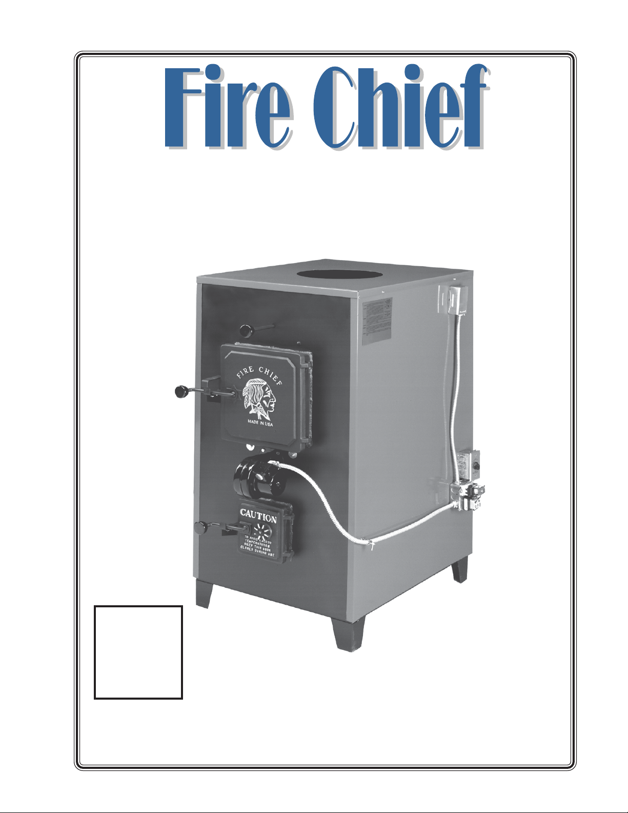
Wood and Coal Burning Furnace
Model 500, 700 and 1100
“E” Series Owner’s Manual
$995
MADEMADE
MADE
MADEMADE
IN
USAUSA
USA
USAUSA
Manufactured by:
Volume XII
August 2009
Victorian Sales
1808 Larkin Williams Road
Fenton, MO 63026
636.343.4747 or 800.875.4788
1
Page 2

Congratulations!
You ha ve selected the finest qualit y wood and coal burning indoor furnace, manufactured with pride in the USA. Please take a few moments to carefully read the owner’s
manual. By taking the time to familiarize yourself with your new Fire Chief, you will be
able to look forward to years of trouble-free, dependable service.
Installation
First: Check Local Codes. The installation must comply with all local rulings and
requirements.
• This furnace must not be installed in trailers, modular or mobile
homes.
• Always have a properly installed and functioning smoke detector
installed in your home.
• To prevent accidental injury, do not allow anyone who is unfamiliar
with the furnace to operate it.
• Spend time familiarizing yourself with your Fire Chief Furnace,
especially the different settings and the effect they have on burn
patterns. It is impossible to state how each setting will affect
your furnace due to variations in settings, fuels and temperatures.
Transportation Damages
Every effort has been made to insure that your Fire Chief will arrive in perfect
condition. Any visible damage should be noted on the freight bill at the time of delivery.
If upon unpacking your Fire Chief you find damage had occurred during transit, notify
your supplier immediately. Your supplier will advise you as to what actions must be
taken to correct the problem.
Disclaimer Notice
The listed BTU rating of your new Fire Chief was obtained under ideal laboratory
testing conditions. The actual BTU output you experience may vary somewhat depending on the type, condition and moisture content of the fuel used; damper adjustment;
chimney type and other variable factors. Therefore, the manufacturer disclaims any
guarantee as to the BTU output or capacity of your furnace. Victorian Sales will void and
disclaim any responsibility for the following: installation of a furnace that has been
altered or modified in any way; installation of the furnace other than as instructed in this
manual; installation and/or use of any component or part not approved by Victorian
Sales for use on this furnace. Be sure to complete and return your warranty card within
thirty (30) days of purchase in order to receive warranty coverage on your furnace.
Manufacturer’s Notice
Please be advised that we periodically make changes to improve our products therefore the information in this manual may not be completely compatible with your
Fire Chief.
THIS IS A WOOD AND COAL BURNING FURNACE
AND SHOULD NOT BE ALTERED IN ANY WAY!
2
Page 3

Table of Contents
Specification/Location .................................................................4
Furnace Components Placement ...................................................5
Ducting/Fuel Requirements .......................................................... 5
Location and Installation .............................................................6
Chimney Recommendations ......................................................... 7
Initial Firing/General Operations .................................................. 8
Ash Removal .............................................................................. 8
General Operation ...................................................................... 9
Creosote Prevention Tips ............................................................. 9
Chimney Fire Warning ................................................................. 9
Blower and Filter Box Assembly Instructions ................................ 10
Wiring Diagram ................................................................... 11-12
Draft Blower Operation .............................................................. 13
Parts Diagram .......................................................................... 14
Parts List ................................................................................. 15
Furnace Parts sold as Kits ......................................................... 16
Grates with Diagram by Model.................................................... 17
Optional Equipment: Back Draft Damper and Hot Water Coil ....................... 18
Troubleshooting Guide ............................................................... 19
Model and Serial Number Registration......................................... 15
Warranty Information ................................................................ 22
ALWAYS KEEP YOUR WOOD COVERED YEAR ROUND.
DRY WOOD WILL PRODUCE MORE BTU OUTPUT
AND LONGER BURN TIMES.
3
Page 4

SPECIFICATIONS:
Laboratory testing has proven that a central solid fuel furnace provides the most
viable solution to the on going problem of homeowner utility dependence. In consideration of this fact, the Fire Chief has been engineered to accommodate the heating
requirements of the average sized home, even during winter’s coldest months. It is
constructed with high grade, heavy gauge steel and is continually welded to assure the
utmost in structural strength. In addition, the firebox is lined with firebrick to ensure
many years of energy efficient service. The design of the secondary combustion chamber increases fuel efficiency by creating a “secondary burn” of smoke and wood gases
before they are vented up the chimney. The cast iron doors are custom fitted to
provide an air tight seal, greatly extending the burn time and insuring maximum efficiency in fuel consumption. The heavy-gauge cast iron roller grate, designed for maximum heat transfer, aid in convenient ash removal and reduce maintenance.
For total comfort and convenience, we added a thermostatically controlled draft
and circulation blower system. These fully automatic components furnish rapid heat
disbursement to your home, minimizing recovery time when the thermostat demands
heat.
We have included all of these features as standard equipment, offering you the
most efficient, durable and affordable indoor wood and coal burning furnace possible.
FORCED HOT AIR CIRCULATION:
The plenum size of your Fire Chief must not be reduced to less than 12" (twelve
inches) round or 79 square inches and must provide a minimum of eighteen inches
between the top of your Fire Chief and the main trunk connection.
CLEARANCES:
The furnace must maintain the following clearances to combustibles: (all mea-
surements are in inches)
Heat Plenum 3"; Chimney Connector 18"; Front 36"; Rear 31"; Side 12"; Main
Furnace 12".
These are minimum clearances and should be strictly adhered to because should a
power outage occur, a dangerous level of heat accumulation may develop.
POWER FAILURE:
In case of power failure to keep your Fire Chief from over-heating and causing
damage to the electrical components, follow these steps:
1. Insure that the by-pass rod is pulled out allowing heat to go up chimney.
2. Close the spin damper control on the ash door.
3. Close the slide cover on the side of the draft motor (see page 10)
4. DO NOT add more fuel (wood) to the firebox.
There is no warranty on electrical components due to power failure.
NOTE: OVER-FIRING OR DELIBERATE ABUSE CAN EASILY BE DETERMINED
UPON INSPECTION AND WILL VOID YOUR WARRANTY.
4
Page 5

DUCT RUNS:
Duct work should be designed so the external static pressure on high speed does
not exceed .02 water column inches while developing air velocities of 600 feet to 1,000
feet per minute in the main trunk duct and 400 feet to 600 feet per minute at the
registers. The heat outlet area should never be less than 12 sq. in. round. The Fire Chief
MUST be installed with a cold air return system. The system should be a minimum of
10% larger than the heat outlet to readily transfer the cold air back to the furnace. Avoid
using 90° elbows in duct runs; 45° elbows provide a better air flow and less resistance.
FUEL RECOMMENDATIONS: Log Size by Model
FC500 - 22” Maximum Log Length;
FC700 - 28” Maximum Log Length;
FC1100 - 34” Maximum Log Length.
We advise using only dry, seasoned hardwoods in your Fire Chief Furnace rather
than highly rosined woods such as pine. Firewood should be cut at least one full season
prior to the time of its intended used for optimum heat output. Firewood should be
stacked to provide a free flow of air between the logs, thus allowing more rapid season
ing of the wood. If wood is stored outdoors, it should be completely covered year round
to protect it from moisture and exposure to the elements.
Use extreme caution when opening the door during operation, temperatures can
exceed 300° - wait at least 10 (ten) seconds after releasing the latch, then proceed to
the fully open position. Opening the door in this manner is designed to eliminate the
possibility of gaseous ignition. Heat resistant gloves are recommended when opening the fuel door, regulating the spin dr aft or emptying the ash pan.
CAUTION: NEVER use chemicals or gasoline to start or maintain your fire. Do not burn
oil, garbage, trash, plastic or any fuel other than wood in your furnace, doing so will void
the warranty.
• DO NOT operate your Fire Chief with the Fuel or Ash Door OPEN.
• DO NOT operate your Fire Chief with the Fuel By-pass Rod OPEN, the handle
must be pushed all of the way IN - except when refueling.
• DO NOT leave the Ash Pan inside your Fire Chief during operation.
WARNING
NEVER fuel your Fire Chief with wet, unseasoned wood or wood that has been exposed
to a recent rainfall. Burning wood with a high moisture content will cause a rapid accu-
mulation of hazardous creosote, which has been proven to be the most common cause
of flue fires.
NEVER burn plastics, any wood product containing glue, paraffin or those treated with
chemical preservatives in your Fire Chief. The combustion of these substances may
release harmful, toxic gases.
DANGER
Due to the risk of uncontrollable fire or explosion DO NOT attempt to use
gasoline, flammable liquids, refuse oil or garbage as an agent of combustion for
your Fire Chief.
5
Page 6

LOCATION AND INSTALLATION:
NOTE: Before beginning your installation, consult with proper local authorities
regarding local codes governing all such applications and installations.
DO NOT connect your Fire Chief Furnace to any chimney that services ANY other
appliance. Your furnace must be placed on a non-combustible floor and position it as
close to the chimney as possible.
Recommendation:
We recommend the purchase of Chimfex™ Dry Chemical Chimney Fire Extinguisher. These are readily available at most stove shops and hardware stores. Smoke
detectors should be installed on all levels of your home. Finally , we recommend installing
a fire extinguisher within the furnace room or area.
CHIMNEY TYPE AND RECOMMENDATION: See diagram on Page 7
Safety requirements demand that your Fire Chief be connected to "Class A"
HT2100 All Fuel or stainless-lined masonry chimney
By definition, "Class A" refers to either a lined masonry chimney or all fuel factory-built chimney. Although experts have expressed differing opinions as to which system is superior, we feel it is a matter of what you find most suitable. R egardless of y our
choice of flue type, for Models 500 and 700, a minimum 6” diameter and for the
Model 1100, a minimum of 8" diameter . In order to create the most efficient draft,
the chimney size should not exceed 12 inches with a minimum of .08 inches water
column of draft. The stove pipe required to connect your furnace to the chimney should
be a minimum of 24 gauge thickness. NEVER USE GALVANIZED PIPE. Horizontal run
should not exceed five feet and should have a minimum rise of two inches per foot. No
installation should have more than two elbows and a 45° elbow is preferable to
a 90° elbow.
As a safety precaution, all pipe sections should be fastened together with a minimum of three sheet metal screws. For your convenience, the crimped male ends of the
pipe should point toward the furnace to form drip-free connections, thereby reducing the
possibility of creosote leakage from the joints. Installing a heat reclaimer in the pipe is
not recommended because it reduces the stack temperature thus causing creosote
formation. Finally , we recommend installing a manually operated cast iron damper in the
stove pipe, between the furnace and the chimney pipe. The addition of the damper will
greatly assist you in regulating your fire and achieving optimum results. Always install a
tee with clean-out cap to the chimney outlet on the back of the furnace. This allows for
easy clean-out of the chimney system.
ONLY.
When using a masonry chimney, you must line the chimney with a stainless steel
liner. The stainless liner will keep the chimney temperature hotter for better draw and
significantly reduce the creosote formation in the chimney. If using this method, use 6”
stainless liner for the FC500 and FC700 and 8” stainless liner for the FC1100.
WARNING
• NEVER use galvanized pipe in your chimney connection - it produces poisonous gases
when subjected to extreme temperatures.
• USE only Masonry or manufactured “Class A” HT2100 All Fuel Chimney for your Fire
Chief .
• INSPECT chimney system periodically for structural integrity.
• CLEAN the chimney system regularly to prevent creosote accumulation.
• NEVER leave the ash pan in your Fire Chief during operation.
6
Page 7
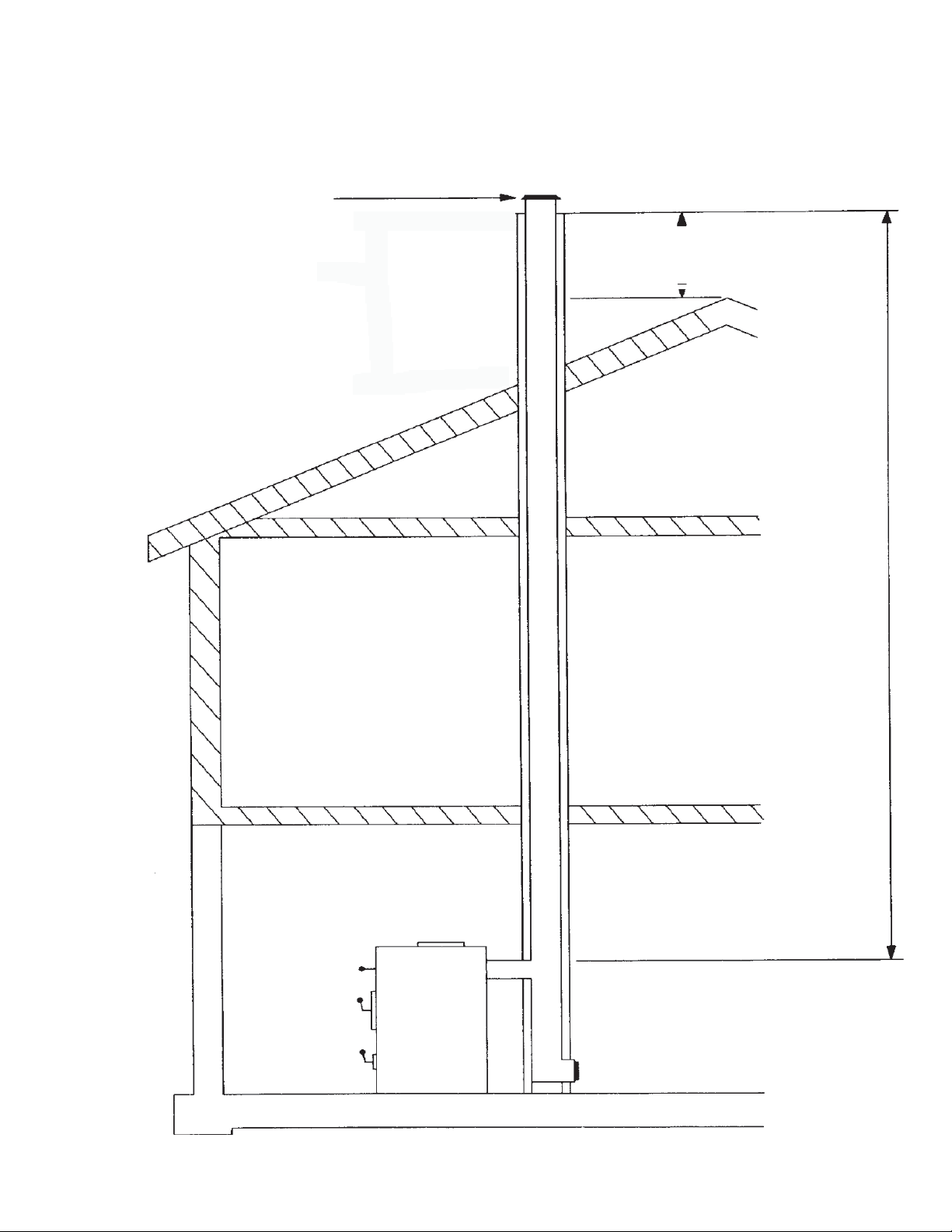
Chimney Recommendations
The termination cap should
be designed to inhibit downdrafting without restricting
the exhaust discharge.
Chimney experts have determined that the
chimney termination should be at least 2' above
the highest portion of the roof that is within a
10' radius of the chimney.
When using a brick chimne, you must
line the entire chimney with stainless
liner. The liner must be the correct
size for the furnace - FC500 and
FC700: 6”; and for the FC1100: 8”.
USE
CLASS "A"
HT2100 ALL
FUEL CHIMNEY
ONLY
The diameter of the chimney stack
should be consistent throughout its
entire length.
The chimney size should be at least
as large as the exhaust stack on the
furnace, but not more than twice it’s
size.
The chimney stack should have a built in air
tight clean out. WARNING: Do not operate
with clean out uncapped.
7
Page 8

STARTING YOUR FIRST “REAL FIRE: Set the wall thermostat to 90°. Check to be
certain the spin draft is wide open to allow oxygen into the firebox. Adjust slide cover on
draft blower
Place several crumpled newspapers on the grate with some dry kindling layered
on top of the papers, ignite the newspaper. When the kindling is burning, add several
small pieces of wood - allow the wood to fully engage in flames. After about 20 minutes
the fire should be established, allowing you to add more wood - do not overload and
smother the fire. Add more wood slowly, so the flames have time to engulf the fresh
wood. Once the fire is burning and there is a glowing ember bed, adjust the draft to
achieve the desired burn pattern. Learning how to adjust the draft to maintain the
desired temperature for your home may take a few days. After a short time you will
know which settings and adjustments work best for your home. Set the wall thermostat to the desired home temperature.
Do not over-fire the furnace. Over-firing by overloading/over-fuelling the furnace
causes the metal to superheat and expand, then cool rapidly which causes cracking,
therefore voiding the warranty. Over-firing or abuse can easily be determined upon
inspection.
It will take about forty minutes to establish a bed of hot embers. When
you have achieved the hot ember bed, add larger pieces of firewood and push
the by-pass rod all of the way in. Within thirty to forty minutes, adjust the spin
draft and the damper to obtain optimum performance. Finally, adjust the wall
thermostat and draft blower cover to a comfortable setting. SEE PAGE 10
NOTE:
Your new Fire Chief is capable of producing a v ery high output of Btu’s. Do not fuel
your furnace to capacity upon initial firing. Instead, we recommend becoming thoroughly familiar with your Fire Chief Furnace before operating at full capacity.
The new steel and metal components in the furnace will have a protective coating
or paint on the surface which could produce an odor during the break-in period. Adequate ventilation within the home and furnace room or area is recommended during
the initial firing and break-in period to accommodate this possibility.
Your new Fire Chief is classified as ha ving airtight construction. This type of design
should enable you to experience an average burn time between six and eight hours per
full load of fuel (dry, seasoned hardwood). However, abnormally cold weather may
reduce the burn time somewhat; therefore if your burn cycle is significantly less, for
instance, two to four hours, you are over-firing your Fire Chief. This type of occurrence
is usually symptomatic of heat demands in excess of furnace capacity. Contact an
authorized professional to determine if your Fire Chief has been improperly sized for
your home.
ASH REMOVAL: Heat resistant gloves are recommended.
In order to remove ashes from your Fire Chief, open the Ash Door and slide the
Ash Pan to the rear of the furnace. Remove the Ash Pan from the furnace and dump
the ashes into an AIRTIGHT METAL container. HOT ashes must always be placed
into an airtight metal container. Alwa ys place the metal container on a NON-COMBUS-
TIBLE surface. Emptying hot ashes into a combustible container is an extreme fire
hazard.
1. The Ash Pan should be removed from your Fire Chief during operation.
We recommend this precautionary measure because if the ash pan is allowed to remain
8
Page 9

inside the furnace during operation, it will become dangerously hot to touch, block the
flow of air under the grates and reduce the efficiency of the furnace.
2. Remove the ashes from your Fire Chief Furnace at least once a day - or as
often as necessary to ensure the ashes do not accumulate to the height of the grates. If
ash build-up occurs at grate level, it will cause premature failure of the grates, voiding the
warranty on the grates. Unacceptably high temperatures will result because the ashes
have restricted the flow of cooling air beneath the grate. This flow of air was designed to
not only cool the grates, but to also provide warmed air for better combustion. If the
ash level is improperly maintained the fire box will be starved for combustion air, greatly
reducing the efficiency and heat output of your Fire Chief.
3. Place hot ashes in a covered, air tight metal container - place the container on
a non-combustible surface. Discard the hot ashes in a safe manner.
4. Wood ash is an especially potent fertilizer.
GENERAL OPERATION:
Always pull the By-pass Rod all the way "OUT" before opening the fuel door.
When opening the fuel door during operation, wait ten seconds after releasing the
first latch, then proceed to the fully open position. The dual latch system has been
incorporated as a safety feature designed to eliminate the possibility of gaseous ignition.
Laboratory testing has determined that when incomplete combustion occurs the partially spent fuel sometimes concentrates large amounts of potentially hazardous gases
within the fire chamber. If the door is opened suddenly under these conditions, the
oxygen may combine with these gases and cause ignition referred to as backflash. Use
EXTREME CAUTION when opening the fuel door.
When reloading the Fire Chief, spread the embers evenly over the grate. Place
smaller pieces of wood or coal on the hot embers and layer larger pieces on top of them.
Finally, due to the wide variety of temperature r anges during the winter, you may experience periods when it is not necessary to fully load the fire chamber in order to maintain
an overnight burn. Y our Fire Chief will oper ate at the highest efficiency by adding fuel in
amounts to maintain comfortable temperatures in your home.
CREOSOTE PREVENTION
To help prevent the formation of creosote within the flue, ALWAYS BURN DRY
SEASONED WOOD. Dry wood burns hotter, allowing flue gases to maintain tempera-
tures above 212°F which should prevent the formation of creosote in the chimney. If
the flue gas temperature falls below 212°F, condensation occurs causing the formation
and accumulation of creosote within the chimney.
As an added precaution, periodic chimney inspections are recommended during
the heating season to determine if creosote formation has occurred. For safety and
efficiency, it is recommended that the chimney system be inspected and cleaned prior
to each heating season.
CHIMNEY FIRE WARNING:
In the event of a chimney fire, take the following actions immediately:
1. Activate and toss a ChimFex™ Dry Chemical Chimney Fire Extinguisher into
the firebox.
2. Close the Ash Door, Fuel Door, Spin Draft and slide cover on Draft Motor.
3. Alert the ENTIRE household and prepare to evacuate if necessary.
4. Call your local Fire Department.
9
Page 10
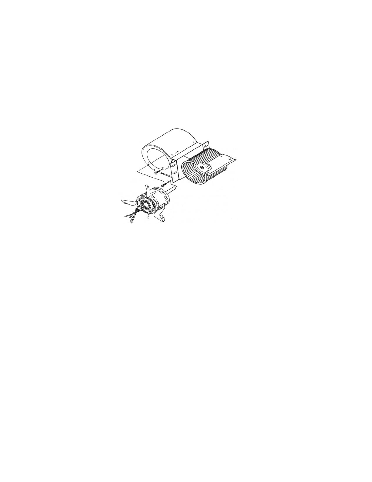
ASSEMBLY INSTRUCTIONS
Please review the parts diagram and list contained on pages 14 thru 17 of this
manual to be assured that you have received all of the required components. If your
inspection reveals a discrepancy , contact your Dealer or call 800.875.4788 for help.
NOTE: for your convenience your Fire Chief has been factory assembled and the electric wiring harness is pre-wired.
BLOWER AND FILTER HOUSING
1. Fasten the right and left side angle br ackets to the circulation blower using 4 each 1/4"
bolts and nuts.
Align Blower with holes on back
side of furnace and firmly attach
with the screws provided.
Attach Blower to the left and right
mounting brackets.
2. Follow the instructions provided with the filter box for assembly. Assemble the Filter Box using the
screws provided. NOTE: The side with the electrical access hole must be mounted to the right side
of the unit.
3. Position filter box at rear of furnace. Cover rear distribution blower. Raise the filter
box approximately 4" off of the floor. Tightly press filter box to the back of the furnace
and use 8 each #10 self-tapping screws to attach it to sides of furnace.
FORCED DRAFT MOTOR
1. Mount the forced draft blower with 3 - 1/4-20 X 1/2" bolts provided.
2. Attach fan limit with 3 - #10 screws in the holes provided.
3. Mount the electrical control center with 4 #10 screws, provided.
4. Secure the flex conduit to the side of the furnace using the bracket provided.(requires 1 screw,
included).
5. Plug motor into the back of the electrical control center.
6. Connect thermostat wire (not provided #28 ga wire) to the two posts located on the side of the
control center. You may locate the wall thermostat next to you existing thermostat in the home. The
thermostat must be installed for the furnace to operate.
7. Plug the three prong grounded plug into a grounded electrical outlet.
REFER TO DIAGRAM ON PAGE 11
10
Page 11

FC500E/FC700E/FC1100E
11
Page 12
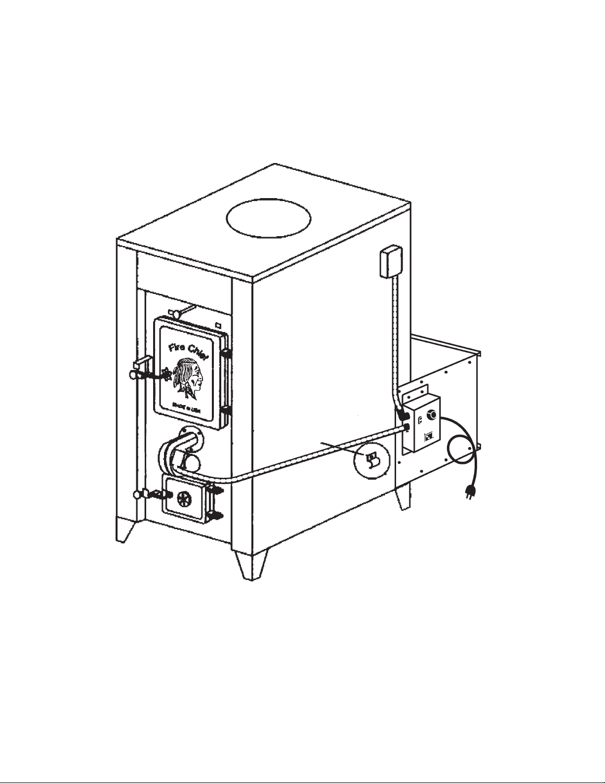
FIRE CHIEF FURNACE
Model FC500E, FC700E and FC1100E
Refer to Assembly Instructions on Page 11
This drawing shows the furnace with the electrical system and filter box
properly installed. The bracket must be attached to the side of the furnace to
secure the conduit. With the connection of thermostat, chimney pipe and duct
work, your furnace installation is complete. Before firing your furnace, be sure
to install a furnace filter - 18” X 25” X 1”.
12
Page 13
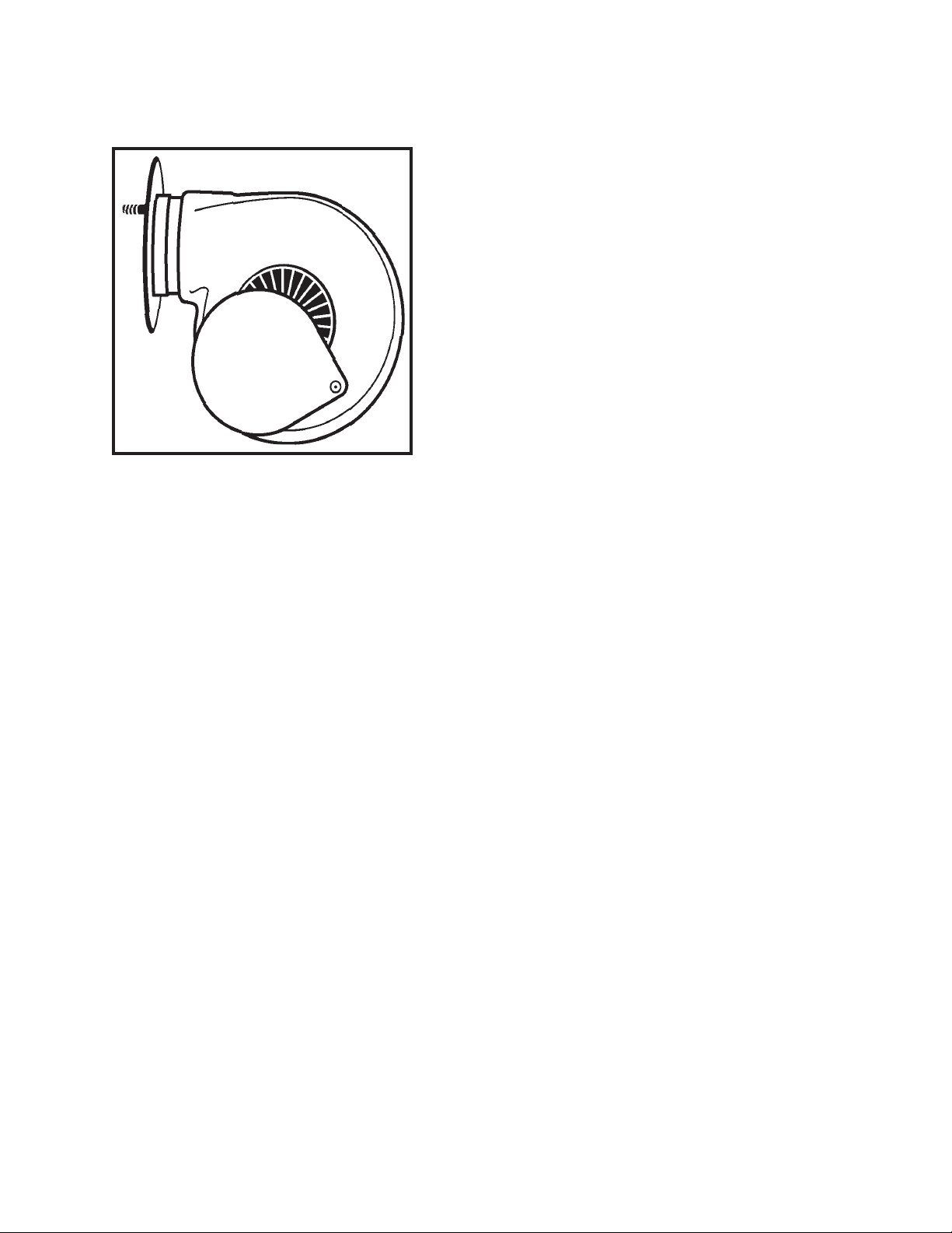
FRONT DRAFT BLOWER:
T
he front draft blower plays an important role in
your Fire Chief furnace’s operation. When the wall
thermostat calls for heat, the draft motor turns on
and supplies fresh air into the firebox producing a
hotter fire which in turns provides more heat in the
heat chamber. The heat is then sent through the
duct system throughout your home. When the wall
thermostat temperature is met, the draft blower
shuts off until the wall thermostat calls for heat,
Slide
Cover
The cover should be fully closed only when there is a power failure and electricity is
lost. With the cover closed, no air is introduced into the firebox, the fire dies, preventing
the furnace from possible overheating and damage.
beginning the cycle again. The draft blower has a
slide cover located on the side of the motor that is
factory preset, with an opening of approximately
3/4”; if adjustment is required, the damper may be
adjusted manually to increase or decrease the air
flow.
There is no warranty on electrical components
caused by power failure.
NOTE: OVER-FIRING OR DELIBERATE ABUSE CAN EASILY BE DETERMINED
UPON INSPECTION AND WILL VOID YOUR WARRANTY.
Always keep your wood covered year round.
Dry wood will produce more Btu output
and a longer burn time.
13
Page 14
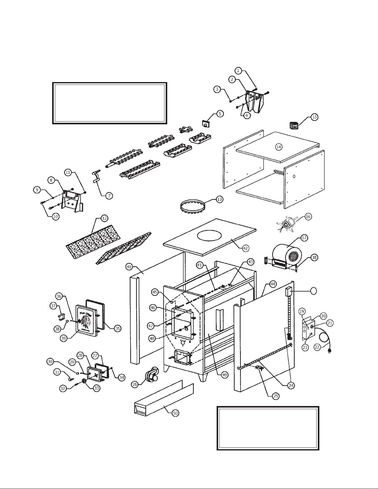
Models 500E,700E,1100E
Parts Diagram
For Grates:
Refer to page 17
Grates listed by Model
14
51
Insulation: Not Shown
Insulation for Furnace
Sides, All Models -
FCIN - 2 per Furnace
Page 15

FIRE CHIEF 500E, 700E AND 1100E PAR T S LIST
ITEM # DESCRIPTION QUANTITY
1 Hex Bolt - 5/16-18 X 2 3/4” 2
2 Rear Cast Plate - FCRCP 1
3 Hex Lock Nut, 5/16-18 2
4 Flat Washer, 9/16 ID 2
5 Roller Grate Retainer - FCMR - Refer to page 17 1
Grates - Refer to Page 17 for Grates by Model
7 Roller Grate Handle - FCSGH 1
8 Front Cast Plate - FCFCP 2
9 Washer, 7/16 ID 2
1 0 Hex Bolt, 3/8 X1 2
1 1 Hex Lock Nut, 5/16 2
12 Firebrick - HTFB
or order as Complete Set by Model, Refer to page 16
1 3 12” Duct Collar - SNGCLR12 1
1 4 Filter Box Assembly - FCFB 1
1 5 Wall Thermostat - FCTHERM 1
1 6 Three Speed Blower Motor - FC3SPMOTOR 1
17 Blower Housing - FCBH 1
1 8 Blower Bracket - FCBR 2
1 9 Rocker Switch for Draft Blower 1
20 Electrical Control Center - Refer to Page 16 1
2 1 3 Speed Blower Switch - FC3SPSWITCH 1
2 2 3’ Grounded Electrc Cord - FC3CORD 1
2 3 Transformer Relay 1
2 4 Conduit Assembly 3/8” - FCCON 2
25 Conduit Clip with Screw - FCCH 1
2 6 Forced Draft Blower - FCDB 1
2 7 Ash Door Gasket, 1/2” - FCGSKT12 1
2 8 Ash Door - FCAD 1
29 Ash Door Handle - FCADH 1
3 0 Ash Door Knob - FCKNOB 1
3 1 Ash Door Latch 1
3 2 Spin Draft Bolt`5 /16-18 X 1 3/4” 1
33 Spin Draft - FCSD 1
3 4 Hex Lock Nut, 5/16-18 1
3 5 Fuel Door Gasket, 5/8” - FCGSKT58 1
36 Fuel Door Handle - FCFDH 1
3 7 Fuel Door Latch 1
3 8 Fuel Door Knob - FCKNOB 1
3 9 Fuel Door - FCFD 1
4 0 Left Side, by Model - FC5LEFT, FC7LEFT, FC11LEFT 1
4 1 Slider Rod, By Model - FC5BR, FC7BR, FC11BR 1
4 2 Furnace Top, By Model - FC5TOP, FC7TOP, FC11TOP 1
4 3 By-Pass Damper 1
4 4 Right Side, By Model -FC5RIGHT, FC7RIGHT, FC11RIGHT 1
4 5 Knob - FCKNOB 1
4 6 Smoke Curtain - FCSC 1
4 7 Smoke Curtain Bolt 2
48 Smoke Curtain Clip 2
49 Firebox 1
5 0 Ash Pan, by Model - FC5AP, FC7AP. FC11AP 1
51 Fan Limit Control 1
and HTFB5 (FC500, only)
15
Page 16

FIRE CHIEF PARTS LIST, continued
Furnace Parts Sold as Kits: For Models/Series as Listed
FC500E; FC700E AND FC1100E Series only - 2009 and Newer Production
Electrical Control Center: Wall Thermostat, Dr aft Blower, Rocker Switch, 3-Speed
Blower Switch, Fan Limit Control, Fan Relay Center and 3’ Cord for each Model.
FC5ECC FC500E Electrical Control Center
FC7ECC FC500E Electrical Control Center
FC11ECC FC1100E Electrical Control Center
FC500; FC700 AND FC1100 Series - 2009 and Earlier Production
Wiring Harness Kit: Includes Wall Thermostat, Fan Relay, Fan Limit Control, Draft
Blower, Junction Box and Wiring for each Model.
FC5HARNESS Wiring Harness for FC500 Series
FC7HARNESS Wiring Harness for FC700 Series
FC11HARNESS Wiring Harness for FC1100 Series
Firebrick Kits: Set of Firebrick for each Furnace
FC5FBKT Complete Set of Firebrick for FC500 Series Furnace - 8 Total -
HTFB: 9” X 4 1/2” X 1 1/4” - 6 pieces and HTFB5: 9” X 3” X
1 1/4” - 2 pieces.
FC7FBKT Complete Set of Firebrick for FC700 Series Furnace - 12 Total -
HTFB: 9” X 4 1/2” X 1 1/4”.
FC11FBKT Complete Set of firebrick for FC1100 Series Furnace - 16 total -
HTFB: 9” X 4 1/2” X 1 1/4”.
Furnace filters are available thru most hardware and home supply stores;
the filter should be changed monthly, during the heating season.
Filter size: 18” X 25” X 1”.
FOR PARTS, CONTACT YOUR DEALER
OR CALL 800.875.4788
16
Page 17
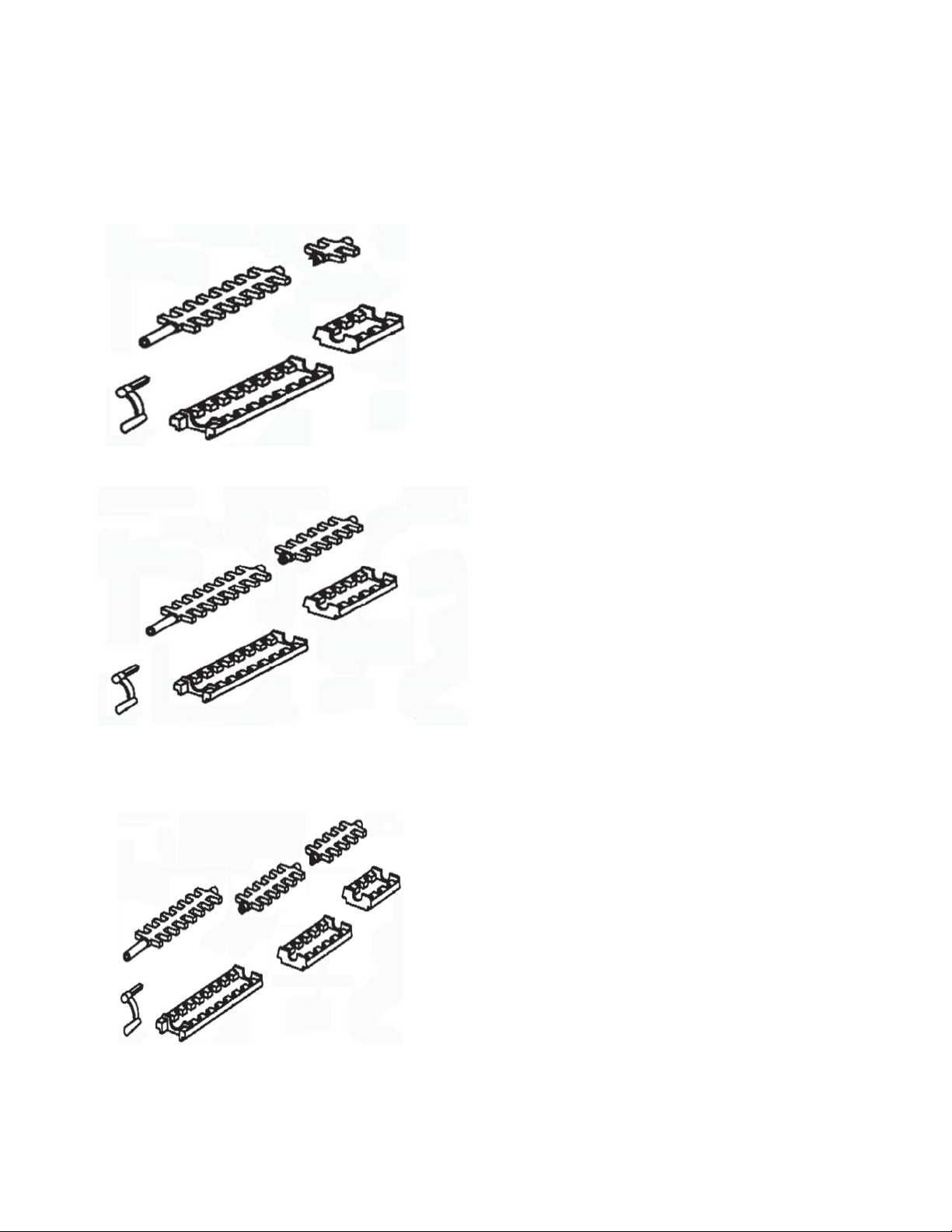
FIRE CHIEF GRATES, BY MODEL
Grates By Model: Refer to Complete Diagram on Page 15 - Diagrams are
for Grates only and quantity needed for each model.
1
Model 500 Grates -
1 Rear Grate, L - FC5RG ......................... 1
2 Front Roller Grate, F - FCFG ................. 1
2
3 Roller Grate Handle, - FCSGH ............... 1
4 Front Grate Housing, B - FCFGH ............ 1
5 Rear Grate Housing, M - FC5RGH .......... 1
5
Not Shown - refer to diagram page 14
3
4
Middle Retainer, Z - FCMR .............................. 1
Model 700 Grates -
1
1 Rear Grate, G - FC711RG..................... 1
2 Front Roller Grate, F - FCFG ................. 1
2
3 Roller Grate Handle, - FCSGH ............... 1
4 Front Grate Housing, B - FCFGH ............ 1
5
5 Rear Grate Housing, C - FC711RGH ...... 1
Not Shown - refer to diagram page 14
3
4
Middle Retainer, Z - FCMR .............................. 1
Model 1100 Grates -
1
1 Rear Grate, Y - FC11RG ....................... 1
2 Middle Grate, G - FC711RG .................. 1
2
3 Front Roller Grate, F - FCFG ................. 1
4 Roller Grate Handle, - FCSGH ............... 1
5 Front Grate Housing, B - FCFGH ............ 1
3
7
6 Middle Grate Housing, C - FC711RGH ... 1
7 Rear Grate Housing, X - FC11RGH......... 1
6
4
5
Not Shown - refer to diagram page 14
Middle Retainer, Z - FCMR .............................. 2
17
Page 18
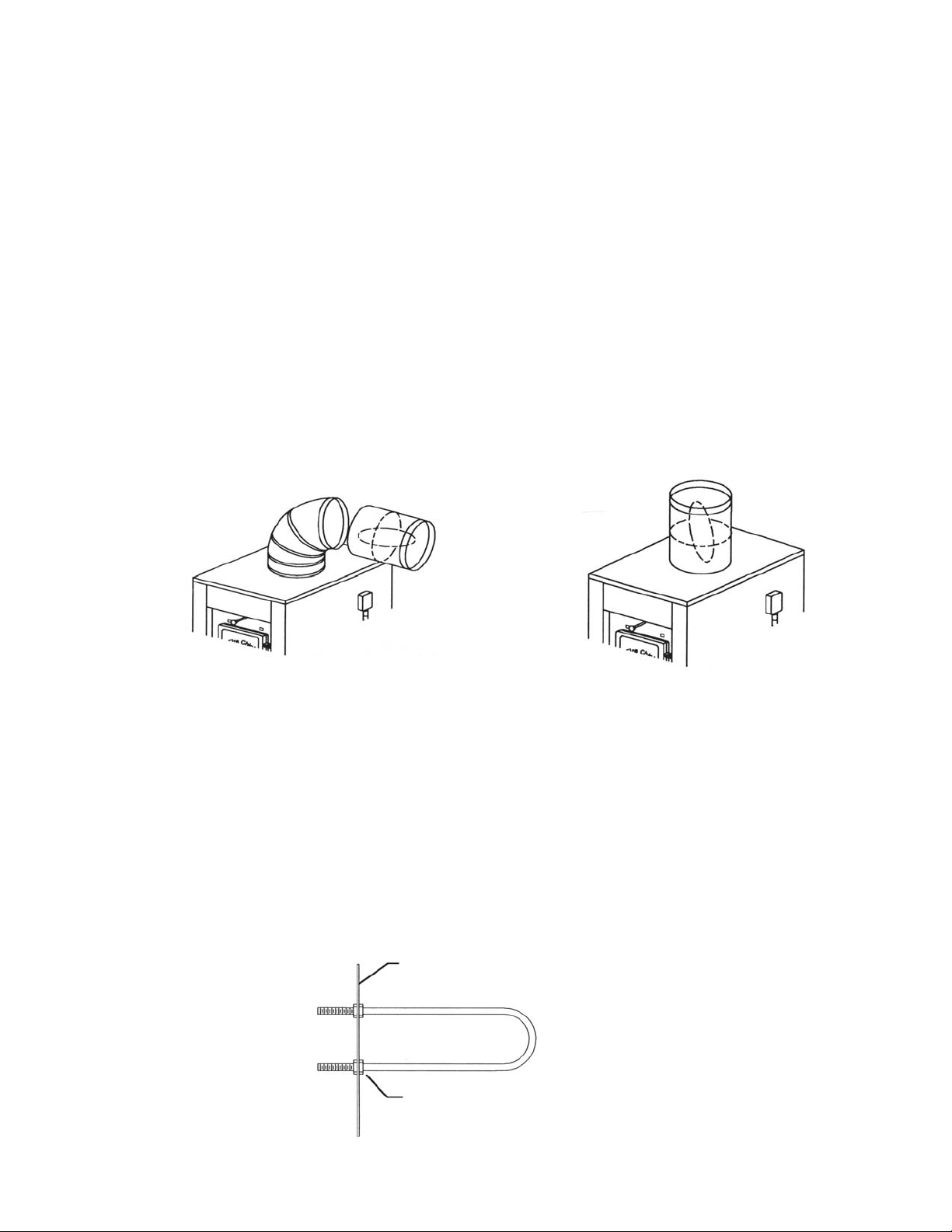
Installation of Optional Equipment
MANUAL BACK DRAFT DAMPER
OPTIONAL ACCESSORY #AM-MD12 Manual Back Draft Damper
The Back Draft Damper may be installed in either a vertical or horizontal section of the 12" round hot air duct. It should be positioned as
close to the plenum opening of the Fire Chief as practical. Press the female
end of the damper over the Fire Chief Furnace collar or male end of the
duct pipe. When properly positioned, the arrows on the air flow decal point
"away" from the Fire Chief Furnace.
NOTE: The back draft damper handle closes off the duct, stopping the cool
air from your air-conditioner from flowing back thru the furnace. Diagrams
below show horizontal and vertical installation. OPEN THE DAMPER AT
THE BEGINNING OF HEATING SEASON - IF THE DAMPER IS IN THE
“CLOSED” POSITION, IT WILL CAUSE THE BLOWER TO RUN CONTINUOUSLY AND CAUSE THE FURNACE TO OVERHEAT CAUSING THE BLOWER TO FAIL.
HORIZONT AL INST ALLA TION
VERTICAL INST ALLA TION
INSTALLING HOT WATER COIL
OPTIONAL ACCESSORY PART #TB-24S Water Coil with Hole Saw
1. Drill two one inch holes at the rear of the furnace just above the firebrick
using the coil as a template with the hole saw provided in the W ater Coil Kit.
2. Place one nut on each end of the water coil and thread each as far as
they will go.
3. Open the loading door and insert the coil through the holes at the end of
the firebox just above the firebrick.
4. From the rear of the furnace, thread on the remaining two nuts and
tighten securely .
5. Have a qualified plumber connect your domestic hot water pipe to the
coil with the appropriate fittings.
REAR WALL OF FIREBOX
DOMESTIC HOT
WA TER COIL
TURN INSIDE NUTS UP
TO END OF THREADS
18
Page 19

TROUBLESHOOTING
PROBLEM
1. Bugs found in wood.
2. Draft Blower will not run.
NOTE: Please verify switch
is in the "ON" position.
PROBABLE CAUSE
• Wood has rotted or has
been laying around for an extended period of time.
• Defective rocker switch
on control center.
• Defective wall thermostat.
• Defective fan relay center.
SUGGESTED REMEDY
Inspect the wood for obvious signs of insect infestation such as burrows or
holes and avoid using if possible. Do not store indoors.
Replace rocker switch.
This can be checked by turning the thermostat to a temperature setting that is
higher than the temperature
in your home. If the draft
blower does not operate, the
thermostat may be defective. Replace if necessary.
Replace fan relay center.
3. Draft blower runs continuously.
• Defective draft motor.
• Improper wiring.
• Defective wall thermostat.
• Thermostat wire is short
circuited.
• Defective fan relay center.
• Home is not being supplied
with a sufficient amount of
heat to satisfy the wall thermostat.
Replace draft motor.
Review wiring diagram. If
wired correctly , seek professional assistance.
Check by turning indicator to
a lower setting than the
temperature in your home.
If the draft blower continues
to run, the thermostat may
be defective. Replace if
necessary.
Check for defective wiring.
Replace fan relay center.
Have a professional determine the proper size furnace
and insulation factor of your
home.
19
Page 20

TROUBLESHOOTING
PROBLEM
4. Circulation blower will
not turn on.
5. Circulation blower runs
continuously.
PROBABLE CAUSE
• Defective fan limit control.
• Defective Blower.
• Improper wiring.
• "OFF" setting on fan limit
control is low.
SUGGESTED REMEDY
Check by moving "ON" position indicator to temperature
position where the blower
should turn on. If the blower
fails to run, replace the fan
limit.
Contact your supplier for
replacement.
Review wiring diagram. If
wired correctly, seek professional assistance.
Remove cover on fan limit
and check for the proper setting. The point indicators
should be set at 100° "OFF"
and 150° "ON". DO NOT attempt to adjust the fan limit
by manually adjusting the dial.
6. Circulation blower vibrates during operation.
• Defective fan limit.
• Improper wiring.
• Backdraft damper is in the
“Closed” position.
• Screw on squirrel cage is
not tight.
Check by moving "ON" or
"OFF" point indicator to a
temperature position where
blower should turn off. If the
blower continues to run, replace the fan limit.
Review wiring diagram. If unit
is wired correctly, seek professional assistance.
Open backdraft damper.
Check squirrel cage alignment
and position so that it does
not drag on the housing during rotation; then tighten the
screw sufficiently to fasten
the squirrel cage securely to
the shaft.
• Balance weights on squirrel cage have become dis-
20
You may attempt to adjust
the weights yourself to obtain
Page 21

TROUBLESHOOTING
PROBLEM
6. Circulation blower vibrates , continued.
7. Odor detected in home
during initial firing.
8. Smoke from the fire
chamber is puffing back
through forced draft motor.
PROBABLE CAUSE
located.
• Defective main bearings
• There is an oily film that
remained on the steel after
the manufacturing process.
Firing the furnace has raised
the temperature of the firebox to a level that is sufficient to vaporize the residue.
• Furnace is not connected
to return air and is drawing
smoke fumes from the flue.
• Excessively long run of
stove pipe from furnace to
flue.
SUGGESTED REMEDY
an acceptable balance. If you
are unsuccessful, contact
your supplier .
Return the blower to your
supplier for replacement.
This odor should disappear
after a few hours of usage.
Connect to return air duct
system.
Relocate the furnace so that
the horizontal run does not
exceed five feet (5’) and
has a two inch (2")
rise per foot.
9. Down draft on chimney caused by one or more
of the following:
• Too many elbows.
• Insufficient flue size.
• Cast iron damper in
"CLOSED" position.
• Flue has a cold spot which
inhibits exhaust discharge
from rising properly . This
21
The run should not contain
more than two (2) elbows.
Replace with a larger flue providing a minimum of 50 (fifty)
square inches of draft area
but not more than 100
square inches of draft area.
If flue is within these specifications, check the draft with
a gauge. Your flue should
provide a minimum of .08
water column inches.
Open damper.
Check entire flue for structural integrity and leakage.
Correct or repair as needed.
Page 22

TROUBLESHOOTING
PROBLEM
9. Down draft on chimney, continued.
PROBABLE CAUSE
symptom may occur in factory built flues because the
insulation has settled or a
seam has ruptured. In masonry flues, mortar loss may
be causing the aspiration of
cooler outside air into the
stack.
• There is an obstruction
outside the chimney , such as
a tree.
• Flue is located too close
to the peak of the roof or
does not rise above it to provide the proper draft.
• Flue is located too close
to another building.
SUGGESTED REMEDY
Replace or re-line chimney.
Remove obstruction.
Increase chimney height.
Increase chimney height.
10. Excessive smoke discharge from fuel door during reloading.
• Obstruction in chimney.
• Excessive ash accumulation.
• Exhaust by-pass rod in
"CLOSED" position.
• Cast iron damper in the
"CLOSED" position.
• Excessively long stove pipe
run from furnace flue.
• Too many elbows.
Check entire chimney system including stove pipe run.
Utilize chimney cleaning device to remove any obstruction or foreign matter.
Remove as necessary.
Always pull the exhaust bypass rod completely forward
before opening the loading
door.
Open damper.
SEE #8
SEE #8
• Insufficient draft.
• Excessive smoke accumulation.
22
SEE #8
SEE #9
Page 23

TROUBLESHOOTING
PROBLEM
11. Flames discharging from
fuel door during reloading.
12. Excessive dirt accumulation surrounding air registers within the home.
PROBABLE CAUSE
• Opening the door has
provided additional oxygen
which has ignited accumulated gases from partially
spent fuel.
• Cast iron damper in
"CLOSED" position.
• Insufficient natural draft
or an obstruction in the flue
system.
• Fire chamber filled to capacity with unburned fuel.
• Smoke discharge from
loading door while refueling.
SUGGESTED REMEDY
Always open the door cautiously and allow the safety
latch system to perform its
designed function of containing ignite gases within the fire
chamber.
Open damper.
SEE #8 AND #9
Do not attempt to overload
furnace.
Always pull exhaust by-pass
rod completely forward before opening fuel door.
13. Home does not achieve
comfortable temperature.
• Furnace is not connected
to return air duct and is
drawing dirt from furnace
room floor and disbursing
through the home.
• Filter box not installed
or no filter in filter box.
• Improper connection
to existing furnace.
• Improperly sized ducting.
Connect to return air duct
system.
Check for proper draft with
gauge. If inadequate, SEE
#8.
Install filter box on furnace.
Install filter in filter box.
Refer to information in the
manual relating to the proper
installation procedures or
contact your local heating and
cooling contractor.
Refer to information in the
manual relating to proper
ducting procedures or consult
your local heating and cooling contractor.
• Excessive dirt accumulation in air filter .
• Combustion chamber
23
Check and replace filter.
FILTER 18” X 25” X 1”
Furnace room may be too
Page 24

TROUBLESHOOTING
PROBLEM
13. Home does not
achieve comfortable temperature, continued
PROBABLE CAUSE
not receiving an adequate
amount of oxygen.
• Inadequate insulation in
the home.
• Your furnace is of inadequate size for you home.
• Slide cover on draft
blower “closed”.
• Fueling furnace with wet
or unseasoned wood.
SUGGESTED REMEDY
airtight. We recommend installing an aperture to the
outside consisting of a minimum of twelve square
inches or 4” round.
Provide additional insulation.
Consult a professional o determine correct sizing.
Open slide cover . See Page
10.
Completely avoid using if at
all possible. If circumstances
necessitate the use of wet
or unseasoned wood, then
fuel the furnace with smaller
loads. This will call for the
thermostat to call for heat
more often, which will initiate
the running of the draft
blower. Consequently, the
fires will be hotter, thereby
reducing the accumulation
of creosote.
14. Rapid accumulation
of creosote in furnace
and flue.
• Use of highly rosined
wood, such as pine.
• Under-firing the furnace
has caused low flue gas
temperature.
24
Completely avoid using if at
all possible. If hardwoods
are not available then fuel
the furnace with smaller
loads. This will cause the
thermostat to call for the
heat more often, which will
initiate the running of the
draft blower. Consequently,
the resultant fires will be
hotter , thereby retarding the
accumulation of creosote.
Install a flue gas thermometer and maintain stack
temperatures between
300° and 400° F.
Page 25

TROUBLESHOOTING
PROBLEM
14. Rapid accumulation of
creosote, continued.
PROBABLE CAUSE
• Insufficient chimney
draft.
• Using Un-insulated stove
pipe for the chimney, especially if the construction is on
the exterior of the home.
• Improper connection in
stove pipe causing air leakage or a structural defect in
the chimney itself .
SUGGESTED REMEDY
SEE #9
DANGER: Never use un-insulated stove pipe as chimney. It must not be used on
the inside of your home due
to high stack temperatures
create an extreme fire hazard. Un-insulated pipe can
not be used as an outside
flues as it causes rapid cooling of the stack gases,
thereby causing them to
condense as creosote on the
inside of the flue.
Inspect entire flue run - from
the exhaust stack of the furnace to the termination cap.
Repair as necessary.
• Firebox not receiving adequate amount of oxygen.
• Use of an unlined masonry
chimney with a large clay tile
opening.
Furnace room may be too
airtight to supply sufficient
amount of oxygen for combustion. We recommend installing an aperture to the
outside consisting of a minimum of fifteen square inches
or 4” round.
Install stainless steel liner in
the masonry chimney to reduce creosote formation and
improve draw. Use appropriately sized stainless liner
for the furnace.
25
Page 26

For your convenience, you may wish to record the following information:
Fire Chief Model Number: ______________________________________
Serial Number: ______________________________________________
Purchase Date: _____________________________________________
Dealer Where Purchased: _______________________________________
Additional Service Information: __________________________________
__________________________________________________________________________________________________
_____________________________________________________________________________
26
Page 27

CertificaCertifica
Certifica
CertificaCertifica
Extent of Coverage: This warranty covers any Fire Chief Furnace sold in the
United States. This warranty applies only if the Fire Chief Furnace is installed,
maintained and operated in accordance with the instructions in the owner’s
manual and local codes. This warranty applies to the original purchaser/owner
of the Fire Chief Furnace and is not transferable. Replacement or repair parts
are warranted for the remaining period of the original part.
All warranty claims must include: date of purchase, model and serial number of
furnace, proof of purchase (dated invoice, bill of sale, cancelled check or payment
record) and the name and address of the dealer from whom you purchased the
furnace.
Victorian Sales warrants the firebox to be free of defects in material and workmanship for five (5) years from date of purchase. The cast iron grates, fuel door, ash
door, cast iron front and rear baffle are warranted from breakage for the life of
the Fire Chief Furnace so long as the furnace may be operated safely in accordance
with the owner’s manual. Cast iron grates and air baffle are not covered by warranty
for burn through caused by the accumulation of ash build-up. The manufacturer
warrants all electrical components one (1) year. Please be advised that the
firebrick and door gaskets are excluded from this warranty. Ov er firing the furnace
will cause the front face of the furnace to expand and contract which may cause the
face to crack and therefore is not covered by warranty. Furthermore, some aesthetic deterioration can be expected as the result of normal operation, therefore
the physical appearance is not guaranteed to remain unchanged.
te of Limited Wte of Limited W
te of Limited W
te of Limited Wte of Limited W
arrantyarranty
arranty
arrantyarranty
In order to exercise the aforementioned warranty, a certified professional must determine the appliance/part to be defective. He or she must submit a written statement to Victorian Sales detailing his assessment of the problem. This assessment
must be accompanied by substantiating proof of purchase (dated invoice, bill of
sale, cancelled check or payment record), model and serial number. Victorian Sales
will then authorize repair or replacement as warranted by the submitted claim. Victorian Sales will not honor expenses incurred from any action that was not expressly
consented to in writing. The owner is hereby notified that he will be obligated to
assume liability for removal, reinstallation, shipping and labor cost involved in servicing/repairing or replacing the part/unit. The merchandise in question must be shipped
via “PREPAID” freight to Victorian Sales. Victorian Sales will return the repaired or
replacement part to the purchaser on a "Freight Collect" basis.
This warranty will be rendered null and void if this part/unit exhibits symptoms of
obvious over-firing, deliberate abuse or negligence, improper installation or is used
for commercial purposes.
Finally, Victorian Sales will not be responsible for any claim not stated in our warranty nor does any implied warranty extend beyond the limits stated above.
If you are unable to receive satisfactory service from your local
dealer, write Victorian Sales with all pertinent information, including
a daytime phone number, a detailed description of the type of problem
you are having and Fire Chief Technical Service will contact you.
Mail To: Victorian Sales 1808 Larkin Williams Road Fenton,
MO 63026
Or call 800.875.4788 - be sure to have model, serial number and purchase date.
27
Page 28

28
 Loading...