


FireBrick FB6202
User Manual
FB6000 Versatile Network Appliance


FireBrick FB6202 User Manual
This User Manual documents Software version V1.19.037
Copyright © 2012 FireBrick Ltd.

Table of Contents
Preface .................................................................................................................................... x
1. Introduction .......................................................................................................................... 1
1.1. The FB6000 ............................................................................................................... 1
1.1.1. Where do I start? ............................................................................................. 1
1.1.2. What can it do? ............................................................................................... 1
1.1.3. Ethernet port capabilities ................................................................................... 2
1.1.4. Product variants in the FB6000 series .................................................................. 2
1.2. About this Manual ...................................................................................................... 2
1.2.1. Version ........................................................................................................... 2
1.2.2. Intended audience ............................................................................................. 2
1.2.3. Document style ................................................................................................ 3
1.2.4. Document conventions ...................................................................................... 3
1.2.5. Comments and feedback .................................................................................... 3
1.3. Additional Resources ................................................................................................... 4
1.3.1. Technical Support ............................................................................................ 4
1.3.2. IRC Channel ................................................................................................... 4
1.3.3. Application Notes ............................................................................................. 4
1.3.4. White Papers ................................................................................................... 4
1.3.5. Training Courses .............................................................................................. 4
2. Getting Started ...................................................................................................................... 5
2.1. IP addressing ............................................................................................................. 5
2.2. Accessing the web-based user interface ........................................................................... 5
2.2.1. Add a new user ............................................................................................... 6
3. Configuration ....................................................................................................................... 9
3.1. The Object Hierarchy .................................................................................................. 9
3.2. The Object Model ....................................................................................................... 9
3.2.1. Formal definition of the object model ................................................................. 10
3.2.2. Common attributes .......................................................................................... 10
3.3. Configuration Methods ............................................................................................... 10
3.4. Web User Interface Overview ..................................................................................... 10
3.4.1. User Interface layout ....................................................................................... 11
3.4.1.1. Customising the layout .......................................................................... 11
3.4.2. Config pages and the object hierarchy ................................................................ 12
3.4.2.1. Configuration categories ........................................................................ 12
3.4.2.2. Object settings ..................................................................................... 13
3.4.3. Navigating around the User Interface ................................................................. 14
3.4.4. Backing up / restoring the configuration .............................................................. 15
3.5. Configuration using XML ........................................................................................... 15
3.5.1. Introduction to XML ....................................................................................... 15
3.5.2. The root element - <config> ............................................................................. 17
3.5.3. Viewing or editing XML .................................................................................. 17
3.5.4. Example XML configuration ............................................................................ 17
3.6. Downloading/Uploading the configuration ..................................................................... 18
3.6.1. Download ...................................................................................................... 18
3.6.2. Upload .......................................................................................................... 19
4. System Administration ......................................................................................................... 20
4.1. User Management ..................................................................................................... 20
4.1.1. Login level .................................................................................................... 21
4.1.2. Configuration access level ................................................................................ 21
4.1.3. Login idle timeout .......................................................................................... 21
4.1.4. Restricting user logins ..................................................................................... 21
4.1.4.1. Restrict by IP address ........................................................................... 21
4.1.4.2. Restrict by profile ................................................................................ 22
4.2. General System settings ............................................................................................. 22
iii

FireBrick FB6202 User Manual
4.2.1. System name (hostname) .................................................................................. 22
4.2.2. Administrative details ...................................................................................... 22
4.2.3. System-level event logging control .................................................................... 22
4.2.4. Home page web links ...................................................................................... 22
4.3. Software Upgrades .................................................................................................... 23
4.3.1. Software release types ..................................................................................... 23
4.3.1.1. Breakpoint releases ............................................................................... 23
4.3.2. Identifying current software version ................................................................... 24
4.3.3. Internet-based upgrade process .......................................................................... 24
4.3.3.1. Manually initiating upgrades .................................................................. 24
4.3.3.2. Controlling automatic software updates .................................................... 25
4.3.4. Manual upgrade .............................................................................................. 25
4.4. Boot Process ............................................................................................................ 26
4.4.1. LED indications ............................................................................................. 26
4.4.1.1. Power LED status indications ................................................................. 26
4.4.1.2. Port LEDs ........................................................................................... 26
5. Event Logging .................................................................................................................... 27
5.1. Overview ................................................................................................................. 27
5.1.1. Log targets .................................................................................................... 27
5.1.1.1. Logging to Flash memory ...................................................................... 27
5.1.1.2. Logging to the Console ......................................................................... 28
5.2. Enabling logging ....................................................................................................... 28
5.3. Logging to external destinations .................................................................................. 28
5.3.1. Syslog .......................................................................................................... 28
5.3.2. Email ............................................................................................................ 29
5.3.2.1. E-mail process logging .......................................................................... 30
5.4. Factory reset configuration log targets ........................................................................... 30
5.5. Performance ............................................................................................................. 30
5.6. Viewing logs ............................................................................................................ 30
5.6.1. Viewing logs in the User Interface ..................................................................... 30
5.6.2. Viewing logs in the CLI environment ................................................................. 31
5.7. System-event logging ................................................................................................. 31
5.8. Using Profiles ........................................................................................................... 31
6. Interfaces and Subnets .......................................................................................................... 32
6.1. Relationship between Interfaces and Physical Ports ......................................................... 32
6.1.1. Port groups .................................................................................................... 32
6.1.2. Interfaces ...................................................................................................... 32
6.2. Defining port groups .................................................................................................. 33
6.3. Defining an interface ................................................................................................. 34
6.3.1. Defining subnets ............................................................................................. 34
6.3.1.1. Using DHCP to configure a subnet .......................................................... 35
6.3.2. Setting up DHCP server parameters ................................................................... 35
6.3.2.1. Fixed/Static DHCP allocations ................................................................ 36
6.3.2.2. Partial-MAC-address based allocations ..................................................... 36
6.4. Physical port settings ................................................................................................. 36
6.4.1. Disabling auto-negotiation ................................................................................ 37
6.4.2. Setting port speed ........................................................................................... 37
6.4.3. Setting duplex mode ........................................................................................ 37
6.4.4. Defining port LED functions ............................................................................ 37
7. Routing .............................................................................................................................. 39
7.1. Routing logic ........................................................................................................... 39
7.2. Routing targets ......................................................................................................... 40
7.2.1. Subnet routes ................................................................................................. 40
7.2.2. Routing to an IP address (gateway route) ............................................................ 40
7.2.3. Special targets ................................................................................................ 40
7.3. Dynamic route creation / deletion ................................................................................. 41
iv

FireBrick FB6202 User Manual
7.4. Routing tables .......................................................................................................... 41
8. Profiles .............................................................................................................................. 42
8.1. Overview ................................................................................................................. 42
8.2. Creating/editing profiles ............................................................................................. 42
8.2.1. Timing control ............................................................................................... 42
8.2.2. Tests ............................................................................................................ 43
8.2.2.1. General tests ........................................................................................ 43
8.2.2.2. Time/date tests ..................................................................................... 43
8.2.2.3. Ping tests ............................................................................................ 43
8.2.3. Inverting overall test result ............................................................................... 43
8.2.4. Manual override ............................................................................................. 43
9. Traffic Shaping ................................................................................................................... 45
9.1. Graphs and Shapers ................................................................................................... 45
9.1.1. Graphs .......................................................................................................... 45
9.1.2. Shapers ......................................................................................................... 45
10. PPPoE .............................................................................................................................. 47
10.1. Types of DSL line and router in the United Kingdom ..................................................... 47
10.2. Definining PPPoE links ............................................................................................ 48
10.2.1. IPv6 ............................................................................................................ 48
10.2.2. Additional options ......................................................................................... 48
10.2.2.1. MTU and TCP fix .............................................................................. 48
10.2.2.2. Service and ac-name ........................................................................... 49
10.2.2.3. Logging ............................................................................................ 49
10.2.2.4. Speed and graphs ............................................................................... 49
11. Tunnels ............................................................................................................................ 50
11.1. FB105 tunnels ......................................................................................................... 50
11.1.1. Tunnel wrapper packets .................................................................................. 50
11.1.2. Setting up a tunnel ........................................................................................ 50
11.1.3. Viewing tunnel status .................................................................................... 51
11.1.4. Dynamic routes ............................................................................................ 51
11.1.5. Tunnel bonding ............................................................................................ 51
11.1.6. Tunnels and NAT ......................................................................................... 52
11.1.6.1. FB6000 doing NAT ............................................................................ 52
11.1.6.2. Another device doing NAT .................................................................. 52
12. System Services ................................................................................................................. 54
12.1. HTTP Server configuration ....................................................................................... 54
12.1.1. Access control .............................................................................................. 54
12.1.1.1. Trusted addresses ............................................................................... 55
12.2. Telnet Server configuration ....................................................................................... 55
12.2.1. Access control .............................................................................................. 55
12.3. DNS configuration ................................................................................................... 56
12.4. NTP configuration ................................................................................................... 56
12.5. SNMP configuration ................................................................................................ 56
13. Network Diagnostic Tools ................................................................................................... 57
13.1. Access check .......................................................................................................... 57
13.2. Packet Dumping ...................................................................................................... 58
13.2.1. Dump parameters .......................................................................................... 58
13.2.2. Security settings required ................................................................................ 59
13.2.3. IP address matching ...................................................................................... 59
13.2.4. Packet types ................................................................................................. 59
13.2.5. Snaplen specification ..................................................................................... 60
13.2.6. Using the web interface .................................................................................. 60
13.2.7. Using an HTTP client .................................................................................... 60
13.2.7.1. Example using curl and tcpdump ........................................................... 60
14. VRRP .............................................................................................................................. 62
14.1. Virtual Routers ....................................................................................................... 62
v

FireBrick FB6202 User Manual
14.2. Configuring VRRP .................................................................................................. 62
14.2.1. Advertisement Interval ................................................................................... 63
14.2.2. Priority ........................................................................................................ 63
14.3. Using a virtual router ............................................................................................... 63
14.4. VRRP versions ....................................................................................................... 63
14.4.1. VRRP version 2 ............................................................................................ 63
14.4.2. VRRP version 3 ............................................................................................ 63
14.5. Compatibility .......................................................................................................... 64
15. Command Line Interface ..................................................................................................... 65
I. Command Line Reference ..................................................................................................... 66
check access ................................................................................................................... 67
clear bgp ....................................................................................................................... 68
clear dhcp ...................................................................................................................... 69
clear l2tp all ................................................................................................................... 70
clear l2tp session ............................................................................................................. 71
clear l2tp tunnel .............................................................................................................. 72
clear pppoe .................................................................................................................... 73
delete config ................................................................................................................... 74
delete data ..................................................................................................................... 75
delete image ................................................................................................................... 76
ethernet reset .................................................................................................................. 77
ethernet stall ................................................................................................................... 78
exit ............................................................................................................................... 79
kill command session ....................................................................................................... 80
kill session ..................................................................................................................... 81
login ............................................................................................................................. 82
logout ............................................................................................................................ 83
panic ............................................................................................................................. 84
ping .............................................................................................................................. 85
quit ............................................................................................................................... 86
reboot ............................................................................................................................ 87
set boot block ................................................................................................................. 88
set command screen width ................................................................................................ 89
show arp ........................................................................................................................ 90
show bgp ....................................................................................................................... 91
show bgp nexthop ........................................................................................................... 92
show bgp peer ................................................................................................................ 93
show bgp routes .............................................................................................................. 94
show bgp summary ......................................................................................................... 95
show boot log ................................................................................................................. 96
show command sessions ................................................................................................... 97
show dhcp ..................................................................................................................... 98
show dns ....................................................................................................................... 99
show ethernet counters ................................................................................................... 100
show ethernet status ....................................................................................................... 101
show fb105 ................................................................................................................... 102
show flash contents ........................................................................................................ 103
show flash log .............................................................................................................. 104
show l2tp ..................................................................................................................... 105
show l2tp session .......................................................................................................... 106
show l2tp sessions ......................................................................................................... 107
show l2tp tunnel ............................................................................................................ 108
show l2tp tunnels .......................................................................................................... 109
show log ...................................................................................................................... 110
show memory ............................................................................................................... 111
show pppoe .................................................................................................................. 112
vi

FireBrick FB6202 User Manual
show profiles ................................................................................................................ 113
show radius .................................................................................................................. 114
show route ................................................................................................................... 115
show routes .................................................................................................................. 116
show sessions ............................................................................................................... 117
show status ................................................................................................................... 118
show subnet .................................................................................................................. 119
show subnets ................................................................................................................ 120
show uptime ................................................................................................................. 121
show tasks .................................................................................................................... 122
show vrrp ..................................................................................................................... 123
start command session .................................................................................................... 124
traceroute ..................................................................................................................... 125
troff ............................................................................................................................. 126
tron ............................................................................................................................. 127
uptime ......................................................................................................................... 128
A. Factory Reset Procedure ..................................................................................................... 129
B. CIDR and CIDR Notation ................................................................................................... 131
C. MAC Addresses usage ....................................................................................................... 133
D. VLANs : A primer ............................................................................................................ 135
Index ................................................................................................................................... 136
vii

List of Figures
2.1. Initial web page in factory reset state ..................................................................................... 6
2.2. Initial "Users" page ............................................................................................................. 6
2.3. Setting up a new user .......................................................................................................... 7
2.4. Configuration being stored ................................................................................................... 7
3.1. Main menu ...................................................................................................................... 11
3.2. Icons for layout controls ..................................................................................................... 12
3.3. Icons for configuration categories ........................................................................................ 12
3.4. The "Setup" category ......................................................................................................... 13
3.5. Editing an "Interface" object ............................................................................................... 13
3.6. Show hidden attributes ....................................................................................................... 14
3.7. Attribute definitions ........................................................................................................... 14
3.8. Navigation controls ........................................................................................................... 15
4.1. Setting up a new user ........................................................................................................ 20
4.2. Software upgrade available notification ................................................................................. 24
4.3. Manual Software upload ..................................................................................................... 25
C.1. Product label showing MAC address range .......................................................................... 133
viii

List of Tables
2.1. IP addresses for computer .................................................................................................... 5
2.2. IP addresses to access the FireBrick ....................................................................................... 5
3.1. Special character sequences ................................................................................................ 16
4.1. User login levels ............................................................................................................... 21
4.2. Configuration access levels ................................................................................................. 21
4.3. General administrative details attributes ................................................................................ 22
4.4. Attributes controlling auto-upgrades ..................................................................................... 25
4.5. Power LED status indications .............................................................................................. 26
5.1. Logging attributes ............................................................................................................. 28
5.2. System-Event Logging attributes .......................................................................................... 31
6.1. Physical port usage options ................................................................................................. 32
6.2. Port LED functions ........................................................................................................... 37
6.3. Example modified Port LED functions .................................................................................. 38
7.1. Route targets .................................................................................................................... 40
12.1. List of system services ..................................................................................................... 54
13.1. Packet dump parameters ................................................................................................... 58
13.2. Packet types that can be captured ....................................................................................... 59
18. Information provided by show fb105 command ..................................................................... 102
C.1. DHCP client names used .................................................................................................. 134
ix

Preface
The FB6000 device is the result of several years of intensive effort to create products based on state of the
art processing platforms, featuring an entirely new operating system and IPv6-capable networking software,
written from scratch in-house by the FireBrick team. Custom designed hardware, manufactured in the UK, hosts
the new software, and ensures FireBrick are able to maximise performance from the hardware, and maintain
exceptional levels of quality and reliability.
The result is a product that has the feature set, performance and reliability to handle mission-critical functions,
effortlessly handling huge volumes of traffic, supporting thousands of customer connections.
x

Chapter 1. Introduction
1.1. The FB6000
1.1.1. Where do I start?
The FB6000 is shipped in a factory reset state. This means it has a default configuration that allows the unit
to be attached directly to a computer, or into an existing network, and is accessible via a web browser on a
known IP address for further configuration.
Besides allowing initial web access to the unit, the factory reset configuration provides a starting point for you
to develop a bespoke configuration that meets your requirements.
A printed copy of the QuickStart Guide is included with your FB6000 and covers the basic set up required to
gain access to the web based user interface. If you have already followed the steps in the QuickStart guide, and
are able to access the FB6000 via a web browser, you can begin to work with the factory reset configuration
by referring to Chapter 3.
Initial set up is also covered in this manual, so if you have not already followed the QuickStart Guide, please
start at Chapter 2.
Tip
The FB6000's configuration can be restored to the state it was in when shipped from the factory. The
procedure requires physical access to the FB6000, and can be applied if you have made configuration
changes that have resulted in loss of access to the web user interface, or any other situation where it
is appropriate to start from scratch - for example, commissioning an existing unit for a different role,
or where you've forgotten an administrative user password. For details on the factory reset procedure
please refer to Appendix A, or consult the QuickStart Guide.
The remainder of this chapter provides an overview of the FB6000's capabilities, and covers your product
support options.
Tip
The latest version of the QuickStart guide for the FB6000 can be obtained from the FireBrick website
at : http://www.firebrick.co.uk/pdfs/quickstart-6000.pdf
1.1.2. What can it do?
The FB6000 series of products is a family of high speed ISP/telcos grade routers and firewalls providing a
range of specific functions.
Key features of the FB6000 family:
• 1U 19" rack mount
• Very low power consumption (typical 20W) - all important with today's power charges in data centres
• Two small fans are the only moving parts for high reliability
• Dual 120/230V AC power feed
• IPv6 built in from the start
• Gigabit performance
1

Introduction
1.1.3. Ethernet port capabilities
The FB6000 has two Ethernet network ports that operate at 1Gb/s. The ports implement auto-negotiation by
default, but operation can be fine-tuned to suit specific circumstances. The function of these ports is very
flexible, and defined by the device's configuration. The ports implement one or more interfaces.
Multiple interfaces can be implemented on a single physical port via support for IEEE 802.1Q VLANs, ideal
for using the FB6000 with VLAN-capable network switches. In this case, a single physical connection can be
made between a VLAN-capable switch and the FB6000, and with the switch configured appropriately, this
physical connection will carry traffic to/from multiple VLANs, and the FB6000 can do Layer 3 processing
(routing/firewalling etc.) between nodes on two or more VLANs.
1.1.4. Product variants in the FB6000 series
• FB6102 High capacity ping monitoring box
• FB6202 Gigabit L2TP LNS with detailed monitoring of all lines
• FB6302 Gigabit BGP router
• FB6402 Gigabit stateful firewall
• FB6502 Gigabit core VoIP SIP switch for ISTP use
• FB6602 Mobile GTPv1 GGSN/L2TP gateway
1.2. About this Manual
1.2.1. Version
Every major FB6000 software release is accompanied by a release-specific version of this manual. This manual
documents software version V1.19.037 - please refer to Section 4.3 to find out more about software releases,
and to see how to identify which software version your FB6000 is currently running.
If your FB6000 is running a different version of system software, then please consult the version of this manual
that documents that specific version, as there may be significant differences between the software versions.
Also bear in mind that if you are not reading the latest version of the manual (and using the latest software
release), references in this manual to external resources, such as the FireBrick website, may be out of date.
Tip
If this is the correct manual for your current software version, then note that there may be a newer
revision of this manual available, still covering the same software version, but with improvements or
corrections to the documentation. We recommend you always ensure you are using the latest revision
available, to be sure you are using the most accurate and up-to-date information. The revision of this
manual can be identified via the Revision History table - this can be found on the home page of the
documentation (when viewing the web based documentation), or near the front of the PDF version
of the documentation.
You can find the latest revision of a manual for a specific software version on the FB6000 software downloads
website [http://www.firebrick.co.uk/software.php?PRODUCT=6000].
1.2.2. Intended audience
This manual is intended to guide FB6000 owners in configuring their units for their specific applications. We
try to make no significant assumption about the reader's knowledge of FireBrick products, but as might be
expected given the target market for the products, it is assumed the reader has a reasonable working knowledge
2

Introduction
of common IP and Ethernet networking concepts. So, whether you've used FireBrick products for years, or
have purchased one for the very first time, and whether you're a novice or a network guru, this Manual sets out
to be an easy to read, definitive guide to FireBrick product configuration for all FireBrick customers.
1.2.3. Document style
At FireBrick, we appreciate that different people learn in different ways - some like to dive in, hands-on,
working with examples and tweaking them until they work the way they want, referring to documentation
as required. Other people prefer to build their knowledge up from first principles, and gain a thorough
understanding of what they're working with. Most people we suspect fall somewhere between these two learning
styles.
This Manual aims to be highly usable regardless of your learning style - material is presented in an order that
starts with fundamental concepts, and builds to more complex operation of your FireBrick. At all stages we hope
to provide a well-written description of how to configure each aspect of the FireBrick, and - where necessary
- provide enough insight into the FireBrick's internal operation that you understand why the configuration
achieves what it does.
1.2.4. Document conventions
Various typefaces and presentation styles are used in this document as follows :-
• Text that would be typed as-is, for example a command, or an XML attribute name is shown in
monospaced_font
• Program (including XML) listings, or fragments of listings are shown thus :-
/* this is an example program listing*/
printf("Hello World!\n");
• Text as it would appear on-screen is shown thus :-
This is an example of some text that would
appear on screen.
Note that for documentation purposes additional
line-breaks may be present that would not be in the on-screen text
• Notes of varying levels of significance are represented thus (colour schemes may differ depending on
signficance) :-
Note
This is an example note.
The significance is identified by the heading text and can be one of : Tip - general hints and tips, for example
to point out a useful feature related to the current discussion ; Note - a specific, but not critical, point relating
to the surrounding text ; Caution - a potentially critical point that you should pay attention to, failure to do
so may result in loss of data, security issues, loss of network connectivity etc.
1.2.5. Comments and feedback
If you'd like to make any comments on this Manual, point out errors, make suggestions for improvement or
provide any other feedback, we would be pleased to hear from you via e-mail at : docs@firebrick.co.uk.
3

Introduction
1.3. Additional Resources
1.3.1. Technical Support
Technical support is available, in the first instance, via the reseller from which you purchased your FireBrick.
FireBrick provide extensive training and support to resellers and you will find them experts in Firebrick
products.
However, before contacting them, please ensure you have :-
• upgraded your FB6000 to the latest version of software (see Section 4.3) and
• are using the latest revision of the manual applicable to that software version and
• have attempted to answer your query using the material in this manual
Many FireBrick resellers also offer general IT support, including installation, configuration, maintenance, and
training. You may be able to get your reseller to develop FB6000 configurations for you - although this will
typically be chargeable, you may well find this cost-effective, especially if you are new to FireBrick products.
If you are not satisfied with the support you are getting from your reseller, please contact us [http://
www.firebrick.co.uk/contact.php].
1.3.2. IRC Channel
A public IRC channel is available for FireBrick discussion - the IRC server is irc.z.je, and the channel
is #firebrick.
1.3.3. Application Notes
FireBrick are building a library of Application Note documents that you can refer to - each Application Note
describes how to use and configure a FireBrick in specific scenarios, such as using the device in a multi-tenant
Serviced Office environment, or using the FireBrick to bond multiple WAN connections together.
1.3.4. White Papers
FireBrick White Papers cover topics that deserve specific discussion - they are not related to specific
Applications, rather they aim to educate interested readers regarding networking protocols, common/best
practice, and real-world issues encountered.
1.3.5. Training Courses
FireBrick provide training courses for the FB2x00 series products, and also training course on general IP
networking that are useful if you are new to networking with IP.
To obtain information about upcoming courses, please contact us via e-mail at :
training@firebrick.co.uk.
4

Chapter 2. Getting Started
2.1. IP addressing
You configure your FireBrick using a web browser - to do this, you need IP connectivity between your computer
and the FireBrick. For a new FB6000 or one that has been factory reset, there are three methods to set this up,
as described below - select the method that you prefer, or that best suits your current network architecture.
• Method 1 - use the FireBrick's DHCP server to configure a computer.
If your computer is already configured (as many are) to get an IP address automatically, you can connect your
computer to port 1 on the FireBrick, and the FireBrick's inbuilt DHCP server should give it an IPv4 address.
• Method 2 - configure a computer with a fixed IP address.
Alternatively, you can connect a computer to port 1 on the FireBrick, and manually configure your computer
to have the fixed IP address(es) shown below :-
Table 2.1. IP addresses for computer
IPv6 IPv4
2001:DB8::2/64 10.0.0.2 ; subnet mask : 255.255.255.0
• Method 3 - use an existing DHCP server to configure the FireBrick.
If your LAN already has a DHCP server, you can connect port 1 of your FireBrick to your LAN, and it will
get an address.
2.2. Accessing the web-based user interface
If you used either Method 1 or Method 2, you should browse to the FireBrick's IP address as listed below:-
Table 2.2. IP addresses to access the FireBrick
IPv6 IPv4
http://[2001:DB8::1] http://10.0.0.1
If you used Method 3, you will need to be able to access a list of allocations made by the DHCP server in
order to identify which IP address has been allocated to the FB6000, and then browse this address from your
computer. If your DHCP server shows the client name that was supplied in the DHCP request, then you will
see FB6000 in the client name field (assuming a factory reset configuration) - if you only have one FB6000 in
factory reset state on your network, then it will be immediately obvious via this client name. Otherwise, you
will need to locate the allocation by cross-referring with the MAC address range used by the FB6000 you are
interested in - if necessary, refer to Appendix C to see how to determine which MAC address you are looking
for in the list of allocations.
Once you are connected to the FB6000, you should see a page with "Configuration needed" prominently
displayed, as shown below :-
5

Getting Started
Figure 2.1. Initial web page in factory reset state
Click on the "edit the configuration" link (red text), which will take you to the main user interface page for
managing the configuration.
2.2.1. Add a new user
You now need to add a new user with a password in order to gain full access to the FireBrick's user interface.
Click on the "Users" icon, then click on the "Add" link to add a user. The "Users" page is shown below, with
the "Add" link highlighted:-
Figure 2.2. Initial "Users" page
Enter a suitable username in the "Name" box, and enter a password (passwords are mandatory), as shown below.
Leave all other checkboxes un-ticked, but see the Tip below regarding the timeout setting.
Note
Take care to enter the password carefully, as the FB6000 does not prompt you for confirmation of
the password.
6

Figure 2.3. Setting up a new user
Getting Started
Tip
You may also want to increase the login-session idle time-out from the default of 5 minutes, especially
if you are unfamiliar with the user-interface. To do that, tick the checkbox next to timeout, and
enter an appropriate value, which should start PT, be followed by a number, and end with units of
either M for minutes, or H for hours.
Click on the Save button near the top of the screen which will save a new configuration that includes your
new user definition.
You should now see a page showing the progress of storing the new configuration in Flash memory :-
Figure 2.4. Configuration being stored
7

Getting Started
On this page there is a "Login" link (in red text)- click on this link and then log in using the username and
password you chose.
We recommend you read Chapter 3 to understand the design of the FB6000's user interface, and then start
working with your FB6000's factory reset configuration. Once you are familiar with how the user interface is
structured, you can find more detail on setting up users in Section 4.1.
8

Chapter 3. Configuration
3.1. The Object Hierarchy
The FB6000 has, at its core, a configuration based on a hierarchy of objects, with each object having one or
more attributes. An object has a type, which determines its role in the operation of the FB6000. The values
of the attributes determine how that object affects operation. Attributes also have a type (or datatype), which
defines the type of data that attribute specifies. This in turn defines what the valid syntax is for a value of that
datatype - for example some are numeric, some are free-form strings, others are strings with a specific format,
such as a dotted-quad IP address. Some examples of attribute values are :-
• IP addresses, and subnet definitions in CIDR format e.g. 192.168.10.0/24
• free-form descriptive text strings, e.g. a name for a firewall rule
• Layer 4 protocol port numbers e.g. TCP ports
• data rates used to control traffic shaping
• enumerated values used to control a feature e.g. defining Ethernet port LED functions
The object hierarchy can be likened to a family-tree, with relationships between objects referred to using terms
such as Parent, Child, Sibling, Ancestor and Descendant. This tree-like structure is used to :-
• group a set of related objects, such as a set of firewall rules - the parent object acts as a container for a group
of (child) objects, and may also contribute to defining the detailed behaviour of the group
• define a context for an object - for example, an object used to define a locally-attached subnet is a child of
an object that defines an interface, and as such defines that the subnet is accessible on that specific interface.
Since multiple interfaces can exist, other interface objects establish different contexts for subnet objects.
Additional inter-object associations are established via attribute values that reference other objects, typically
by name, e.g. a firewall rule can specify one of several destinations for log information to be sent when the
rule is processed.
3.2. The Object Model
The term 'object model' is used here to collectively refer to :-
• the constraints that define a valid object hiearchy - i.e. which object(s) are valid child objects for a given
parent object, how many siblings of the same type can exist etc.
• for each object type, the allowable set of attributes, whether the attributes are mandatory or optional, their
datatypes, and permissible values of those attributes
The bulk of this User Manual therefore serves to document the object model and how it controls operation of
the FB6000.
Tip
This version of the User Manual may not yet be complete in its coverage of the full object model.
Some more obscure attributes may not be covered at all - some of these may be attributes that are
not used under any normal circumstances, and used only under guidance by support personnel. If you
9

Configuration
encounter attribute(s) that are not documented in this manual, please refer in the first instance to the
documentation described in Section 3.2.1 below. If that information doesn't help you, and you think
the attribute(s) may be relevant to implementing your requirements, please consult the usual support
channel(s) for advice.
3.2.1. Formal definition of the object model
The object model has a formal definition in the form of an XML Schema Document (XSD) file, which is itself an
XML file, normally intended for machine-processing. A more readable version of this information is available
by following the "Doc" link that is present against each software release on the FB6000 software downloads
website [http://www.firebrick.co.uk/software.php?PRODUCT=6000].
Note, however, that this is reference material, containing only brief descriptions, and intended for users who
are familiar with the product, and in particular, for users configuring their units primarily via XML.
The XSD file is also available on the software downloads website by following the "XSD" link that is present
against each software release.
3.2.2. Common attributes
Most objects have a comment attribute which is free-form text that can be used for any purpose. Similarly,
most objects have a source attribute that is intended for use by automated configuration management tools.
Neither of these attributes have a direct effect on the operation of the FB6000.
3.3. Configuration Methods
The configuration objects are created and manipulated by the user via one of two configuration methods :
• web-based graphical User Interface accessed using a supported web-browser
• an XML (eXtensible Markup Language) file representing the entire object hierarchy, editable via the web
interface or can be uploaded to the FB6000
The two methods operate on the same underlying object model, and so it is possible to readily move between
the two methods - changes made via the User Interface will be visible as changes to the XML, and vice-versa.
Users may choose to start out using the User Interface, and - as experience with the object model and the XML
language develops - increasingly make changes in the XML environment. For information on using XML to
configure the FB6000, please refer to Section 3.5.
3.4. Web User Interface Overview
This section provides an overview of how to use the web-based User Interface. We recommend that you
read this section if you are unfamiliar with the FB6000, so that you feel comfortable with the design of the
User Interface. Later chapters cover specific functionality topics, describing which objects are relevant, any
underlying operational principles that are useful to understand, and what effect the attributes (and their values)
have.
The web-based User Interface provides a method to create the objects that control operation of the FB6000.
Internally, the User Interface uses a formal definition of the object model to determine where (in the hierarchy)
objects may be created, and what attributes may exist on each object, so you can expect the User Interface to
always generate valid XML.
1
If the User Interface does not generate valid XML - i.e. when saving changes to the configuration the FireBrick reports XML errors, then this
may be a bug - please check this via the appropriate support channel(s).
1
10

Configuration
Additionally, the web User Interface provides access to the following items :-
• status information, such as DHCP server allocations, FB105 tunnel information and system logs
• network diagnostic tools, such as Ping and Traceroute ; there are also tools to test how the FB6000 will
process particular traffic, allowing you to verify your firewalling is as intended
• traffic graphs
By default, access to the web user interface is available to all users, from any IP address. If you don't require
such open access, you may wish to restrict access using the settings described in Section 12.1.
3.4.1. User Interface layout
The User Interface has the following general layout :-
• a 'banner' area at the top of the page, containing the FireBrick logo, model number and system name
• a main-menu, with sub-menus that access various parts of the user interface ; the main-menu can be shown
vertically or horizontally - sub-menu appearance depends on this display style : if the main-menu is vertical,
sub-menus are shown by 'expanding' the menu vertically ; if the main-menu is horizontal, sub-menus are
shown as pull-down menus
• a 'footer' area at the bottom of the page, containing layout-control icons and showing the current software
version
• the remaining page area contains the content for the selected part of the user-interface
Figure 3.1 shows the main menu when it is set to display horizontally. Note that the main-menu items themselves
have a specific function when clicked - clicking such items displays a general page related to that item - for
example, clicking on Status shows some overall status information, whereas sub-menu items under Status
display specific categories of status information.
Figure 3.1. Main menu
The user interface pages used to change the device configuration are referred to as the 'config pages' in this
manual - these pages are accessed by clicking on the "Edit" item in the sub-menu under the "Config" mainmenu item.
Note
The config pages utilise JavaScript for their main functionality ; you must therefore have JavaScript
enabled in your web browser in order to configure your FB6000 using the web interface.
3.4.1.1. Customising the layout
The following aspects of the user interface layout can be customised :-
• The banner area can be reduced in height, or removed all together
• The main menu strip can be positioned vertically at the left or right-hand sides, or horizontally at the top
(under the banner, if present)
11

Configuration
Additionally, you can choose to use the default fonts that are defined in your browser setup, or use the fonts
specified by the user interface.
These customisations are controlled using three icons on the left-hand side of the page footer, as shown in
Figure 3.2 below :-
Figure 3.2. Icons for layout controls
The first icon, an up/down arrow, controls the banner size/visibility and cycles through three settings : full size
banner, reduced height banner, no banner. The next icon, a left/right arrow, controls the menu strip position
and cycles through three settings : menu on the left, menu on the right, menu at the top. The last icon, the letter
'A', toggles between using browser-specified or user-interface-specified fonts.
Layout settings are stored in a cookie - since cookies are stored on your computer, and are associated with
the DNS name or IP address used to browse to the FB6000, this means that settings that apply to a particular
FB6000 will automatically be recalled next time you use the same computer/browser to connect to that FB6000.
3.4.2. Config pages and the object hierarchy
The structure of the config pages mirrors the object hierachy, and therefore they are themselves naturally
hierachical. Your postition in the hierachy is illustrated in the 'breadcrumbs' trail at the top of the page, for
example :-
Firewall/mapping rules :: rule-set 1 of 3 (filters) :: rule 7 of 19 (ICMP)
This shows that the current page is showing a rule, which exists within a rule-set, which in turn is in the
"Firewall/mapping rules" category (see below).
3.4.2.1. Configuration categories
Configuration objects are grouped into a number of categories. At the top of the config pages is a set of icons,
one for each category, as shown in Figure 3.3 :-
Figure 3.3. Icons for configuration categories
Within each category, there are one or more sections delimited by horizontal lines. Each of these sections has a
heading, and corresponds to a particular type of top-level object, and relates to a major part of the configuration
that comes under the selected category. See Figure 3.4 for an example showing part of the "Setup" category,
which includes general system settings (the system object) and control of system services (network services
provided by the FB6000, such as the web-interface web server, telnet server etc., controlled by the services
object).
12

Configuration
Figure 3.4. The "Setup" category
Each section is displayed as a tabulated list showing any existing objects of the associated type. Each row of
the table corresponds with one object, and a subset (typically those of most interest at a glance) of the object's
attributes are shown in the columns - the column heading shows the attribute name. If no objects of that type
exist, there will be a single row with an "Add" link. Where the order of the objects matter, there will be an 'Add'
link against each object - clicking an 'Add' link for a particular object will insert a new object before it. To add
a new object after the last existing one, click on the 'Add' link on the bottom (or only) row of the table.
Tip
If there is no 'Add' link present, then this means there can only exist one object of that type, and such
an object already exists. The existing object may have originated from the factory reset configuration.
You can 'push-down' into the hierarchy by clicking the 'Edit' link in a table row. This takes you to a page
to edit that specific object. The page also shows any child objects of the object being edited, using the same
horizontal-line delimited section style used in the top-level categories. You can navigate back up the hierarchy
using various methods - see Section 3.4.3.
3.4.2.2. Object settings
The details of an object are displayed as a matrix of boxes, one for each attribute associated with that object
type. Figure 3.5 shows an example for an interface object (covered in Chapter 6) :-
Figure 3.5. Editing an "Interface" object
By default, more advanced or less frequently used attributes are hidden - if this applies to the object being
edited, you will see the text shown in Figure 3.6. The hidden attributes can be displayed by clicking on the
link "Show all".
13
Configuration
Figure 3.6. Show hidden attributes
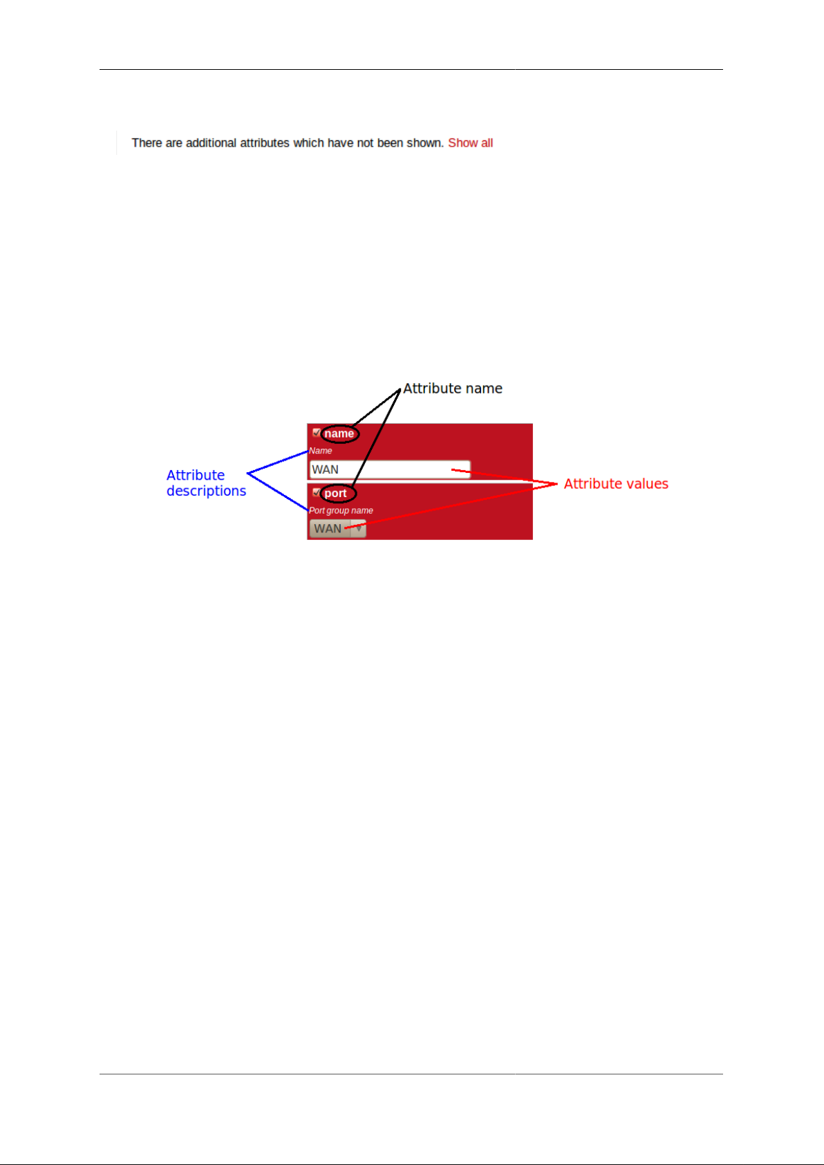
Each box in the matrix contains the following :-
• a checkbox - if the checkbox is checked, an appropriate value entry widget is displayed, otherwise, a default
value is shown and applied for that setting.
• the attribute name - this is a compact string that exactly matches the underlying XML attribute name
• a short description of the attribute
These can be seen in Figure 3.7 :-
Figure 3.7. Attribute definitions
If the attribute value is shown in a 'strike-through' font (with a horizontal line through it mid-way vertically),
this illustrates that the attribute can't be set - this will happen where the attribute value would reference an
instance of particular type of object, but there are not currently any instances of objects of that type defined.
Tip
Since the attribute name is a compact, concise and un-ambiguous way of referring to an attribute, please
quote attribute names when requesting technical support, and expect technical support staff to discuss
your configuration primarily in terms of attribute (and object/element) names, rather than descriptive
text, or physical location on your screen (both of which can vary between software releases).
Note
When the checkbox associated with an attribute is unchecked, this means the attribute value is not
(explicitly) specified, and a default value is used. The default value is specified by the object model
(see Section 3.2 via its associated formal definition (XSD file). When the checkbox is unchecked,
the default value is shown under the attribute description text, and in the XML configuration (see
Section 3.5), there will be no name="value" specification present for the attribute.
3.4.3. Navigating around the User Interface
You navigate around the hierarchy using one or more of the following :-
• configuration category icons
• the breadcrumbs - each part of the breadcrumbs (delimited by the :: symbol) is a clickable link
• the in-page navigation buttons, shown in Figure 3.8 : "Up" - move one level up in the object hierachy, "Prev"
- Previous object in a list, and "Next" - Next object in a list.
14

Configuration
Figure 3.8. Navigation controls
Caution
The configuration pages are generated on-the-fly using JavaScript within your web browser
environment (i.e. client-side scripting). As such, the browser is essentially unaware of changes to
page content, and cannot track these changes - this means the browser's navigation buttons (Back,
Forward), will not correctly navigate through a series of configuration pages.
Please take care not to use the browser's Back button whilst working through configuration pages navigation between such pages must be done via the buttons provided on the page - "Prev", "Next"
and "Up".
Navigating away from an object using the supported navigation controls doesn't cause any modifications to
that object to be lost, even if the configuration has not yet been saved back to the FB6000. All changes are
initially held in-memory (in the web browser itself), and are committed back to the FireBrick only when you
press the Save button.
The navigation button area, shown in Figure 3.8, also includes three other buttons :-
• New : creates a new instance of the object type being edited - the new object is inserted after the current one ;
this is equivalent to using the "Add" link one level up in the hierarchy
• Erase : deletes the object being edited - note that the object will not actually be erased until the configuration
is saved
• Help : browses to the online reference material (as desribed in Section 3.2.1) for the object type being edited
Caution
If you Add a new object, but don't fill in any parameter values, the object will remain in existence
should you navigate away. You should be careful that you don't inadvertently add incompletely setup
objects this way, as they may affect operation of the FireBrick, possibly with a detrimental effect.
If you have added an object, perhaps for the purposes of looking at what attributes can be set on it,
remember to delete the object before you navigate away -- the "Erase" button (see Figure 3.8) is used
to delete the object you are viewing.
3.4.4. Backing up / restoring the configuration
To back up / save or restore the configuration, start by clicking on the "Config" main-menu item. This will
show a page with a form to upload a configuration file (in XML) to the FB6000 - also on the page is a link
"Download/save config" that will download the current configuration in XML format.
3.5. Configuration using XML
3.5.1. Introduction to XML
An XML file is a text file (i.e. contains human-readable characters only) with formally defined structure and
content. An XML file starts with the line :-
15

Configuration
<?xml version="1.0" encoding="UTF-8"?>
This defines the version of XML that the file complies with and the character encoding in use. UTF-8 is used
everywhere by the FireBrick.
The XML file contains one or more elements, which may be nested into a hiearchy.
Note
In XML, the configuration objects are represented by elements, so the terms object and element are
used interchangeably in this manual.
Each element consists of some optional content, bounded by two tags - a start tag AND an end tag.
A start tag consists of the following sequence of characters:-
• a < character
• the element name
• optionally, a number of attributes
• a > character
An end tag consists of the following sequence of characters:-
• a < character
• a / character
• the element name
• a > character
If an element needs no content, it can be represented with a more compact self closing tag. A self closing tag
is the same as a start tag but ends with /> and then has no content or end tag.
Since the <, > and " characters have special meaning, there are special ('escape') character sequences starting
with the ampersand character that are used to represent these characters. They are :-
Table 3.1. Special character sequences
Sequence Character represented
< <
> >
" "
& &
Note that since the ampersand character has special meaning, it too has an escape character sequence.
Attributes are written in the form : name="value" or name='value'. Multiple attributes are separated
by white-space (spaces and line breaks).
Generally, the content of an element can be other child elements or text. However, the FB6000 doesn't use text
content in elements - all configuration data is specified via attributes. Therefore you will see that elements only
contain one or more child elements, or no content at all. Whilst there is generally not any text between the tags,
white space is normally used to make the layout clear.
16

Configuration
3.5.2. The root element - <config>
At the top level, an XML file normally only has one element (the root element), which contains the entire
element hierarchy. In the FB6000 the root element is <config>, and it contains 'top-level' configuration
elements that cover major areas of the configuration, such as overall system settings, interface definitions,
firewall rule sets etc.
In addition to this User Manual, there is reference material is available that documents the XML elements refer to Section 3.2.1.
3.5.3. Viewing or editing XML
The XML representation of the configuration can be viewed and edited (in text form) via the web interface
by clicking on "XML View" and "XML Edit" respectively under the main-menu "Config" item. Viewing the
configuration is, as you might expect, 'read-only', and so is 'safe' in as much as you can't accidentally change
the configuration.
3.5.4. Example XML configuration
An example of a simple, but complete XML configuration is shown below, with annotations pointing out the
main elements
<?xml version="1.0" encoding="UTF-8"?>
<config xmlns="http://firebrick.ltd.uk/xml/fb2700/"
xmlns:xsi="http://www.w3.org/2001/XMLSchema-instance"
xsi:schemaLocation="http://firebrick.ltd.uk/xml/fb2700/ ...
timestamp="2011-10-14T12:24:07Z"
patch="8882">
<system name="gateway"
contact="Peter Smith"
location="The Basement"
log-panic="fb-support">
</system>
<user name="peter"
full-name="Peter Smith"
password="FB105#4D42454D26F8BF5480F07DFA1E41AE47410154F6"
timeout="PT3H20M"
config="full"
level="DEBUG"/>
<log name="default"/>
<log name="fb-support">
<email to="crashlog@firebrick.ltd.uk"
comment="Crash logs emailed to FireBrick Support"/>
</log>
<services>
<ntp timeserver="pool.ntp.org"/>
<telnet log="default"/>
<http />
<dns domain="watchfront.co.uk"
resolvers="81.187.42.42 81.187.96.96"/>
17

Configuration
</services>
<port name="WAN"
ports="1"/>
<port name="LAN"
ports="2"/>
<interface name="WAN"
port="WAN">
<subnet name="ADSL"
ip="81.187.106.73/30"/>
</interface>
<interface name="LAN"
port="LAN">
<subnet name="LAN"
ip="81.187.96.94/28"/>
<dhcp name="LAN"
ip="81.187.96.88-92"
log="default"/>
</interface>
</config>
sets some general system parameters (see Section 4.2)
defines a single user with the highest level of access (DEBUG) (see Section 4.1)
defines a log target (see Chapter 5)
configures key system services (see Chapter 12)
defines physical-port group (see Section 6.1)
defines an interface, with one subnet and a DHCP allocation pool (see Chapter 6)
3.6. Downloading/Uploading the configuration
The XML file may be retrieved from the FireBrick, or uploaded to the FireBrick using HTTP transfers done
via tools such as curl. Using these methods, configuration of the FB6000 can be integrated with existing
administrative systems.
Note
Linebreaks are shown in the examples below for clarity only - they must not be entered on the
command-line
3.6.1. Download
To download the configuration from the FB6000 you need to perform an HTTP GET of the following URL :-
http://<FB6000 IP address or DNS name>/config/config
An example of doing this using curl, run on a Linux box is shown below :-
curl http://<FB6000 IP address or DNS name>/config/config
18

Configuration
--user "username:password" --output "filename"
Replace username and password with appropriate credentials.
The XML configuration file will be stored in the file specified by filename - you can choose any file extension
you wish (or none at all), but we suggest that you use .xml for consistency with the file extension used when
saving a configuration via the User Interface (see Section 3.4.4).
3.6.2. Upload
To upload the configuration to the FB6000 you need to send the configuration XML file as if posted by a web
form, using encoding MIME type multi-part/form-data.
An example of doing this using curl, run on a Linux box is shown below :-
curl http://<FB6000 IP address or DNS name>/config/config
--user "username:password" --form config="@filename"
3.1. IP address groups
An IP address group is a named definition of a range of IP addresses, which can be referenced in many places
where you would otherwise explicitly specify such ranges. This allows you to specify commonly occuring
ranges (for example a trusted group of addresses) in one place, which aids maintainability, and then reference
them by name, which speeds configuration and aids readability.
An IP address group is defined using an ip-group top-level object - in the web user interface, click on the
"IP group" category icon to create and edit these objects.
19

Chapter 4. System Administration
4.1. User Management
You will have created your first user as part of the initial setup of your FB6000, as detailed in either the
QuickStart Guide or in Chapter 2 in this manual.
To create, edit or delete users, browse to the config pages by clicking the "Edit" item in the sub-menu under
the "Config" main-menu item, then click on the "Users" category icon. Click on the "Edit" link adjacent to the
user you wish to edit, or click on the "Add" link to add a user.
To delete a user, click the appropriate "Edit" link, then click the "Erase" button in the navigation controls - see
Figure 3.8. As with any such object erase operation, the object will not actually be erased until the configuration
is saved.
Once you have added a new user, or are editing an existing user, the object editing page will appear, as shown
in Figure 4.1 :-
Figure 4.1. Setting up a new user
The minimum attributes that must be specified are name, which is the username that you type in when logging
in, and password - passwords are mandatory on the FB6000.
You can optionally provide a full name for the specified username, and a general comment field value.
20

System Administration
4.1.1. Login level
A user's login level is set with the level attribute, and determines what CLI commands the user can run. The
default, if the level attribute is not specified, is ADMIN - you may wish to downgrade the level for users who
are not classed as 'system administrators'.
Table 4.1. User login levels
Level Description
NOBODY Unknown or not logged in user
GUEST Guest user
USER Normal unprivileged user
ADMIN System administrator
DEBUG System debugging user
4.1.2. Configuration access level
The configuration access level determines whether a user has read-only or read-write access to the
configuration, as shown in Table 4.2 below. This mechanism can also be used to deny all access to the
configuration using the none level, without actually deleting the user definition.
This setting is distinct from, and not connected with, the login level described above. You can use the access
level to define, for example, whether a USER login-level user can modify the configuration. Typically an
ADMIN (or DEBUG) login-level user would always be granted full access, so for ADMIN or DEBUG level
user's, the default of full is suitable.
Table 4.2. Configuration access levels
Level Description
none No access unless explicitly listed
view View only access (no passwords)
read Read only access (with passwords)
full Full view and edit access - DEFAULT
4.1.3. Login idle timeout
To improve security, login sessions to either the web user interface, or to the command-line interface (via telnet,
see Chapter 15), will time-out after a period of inactivity. This idle time-out defaults to 5 minutes, and can be
changed by setting the timeout attribute value.
The time-out value is specified using the syntax for the XML Period data type - this syntax consists of the
prefix PT, followed by one or more components of a time value. Each component consists of a number followed
by a unit - H (hours), M (minutes), S (seconds). As an example, the value PT5M30S represents 5 minutes and
30 seconds.
To set a user's time-out in the user interface, tick the checkbox next to timeout, and enter a value in the
format described above.
4.1.4. Restricting user logins
4.1.4.1. Restrict by IP address
You can restrict logins by a given user to be allowed only from specific IP addresses, using the allow attribute.
This restriction is per-user, and is distinct from, and applies in addition to, any restrictions specified on either the
21

System Administration
web or telnet (for command line interface access) services (see Section 12.1 and Section 12.2), or any firewall
rules that affect web or telnet access to the FB6000 itself.
4.1.4.2. Restrict by profile
By specifying a profile name using the profile attribute, you can allow logins by the user only when the
profile is in the Active state (see Chapter 8). You can use this to, for example, restrict logins to be allowed
only during certain times of the day, or you can effectively suspend a user account by specifying an alwaysInactive profile.
4.2. General System settings
The system top-level object can specify attributes that control general, global system settings. The available
attributes are described in the following sections, and can be configured in the User Interface by choosing the
"Setup" category, then clicking the "Edit" link under the heading "System settings".
The software auto upgrade process is controlled by system objects attributes - these are described in
Section 4.3.3.2.
4.2.1. System name (hostname)
The system name, also called the hostname, is used in various aspects of the FB6000's functions, and so we
recommend you set the hostname to something appropriate for your network.
The hostname is set using the name attribute.
4.2.2. Administrative details
The attributes shown in Table 4.3 allow you to specify general administrative details about the unit :-
Table 4.3. General administrative details attributes
Attribute Purpose
comment General comment field
contact Contact name
intro Text that appears on the 'home' page - the home page
is the first page you see after logging in to the FB6000.
This text is also displayed immediately after you login
to a command-line session.
location Physical location description
4.2.3. System-level event logging control
The log and log-... attributes control logging of events related to the operation of the system itself. For
details on event logging, please refer to Chapter 5, and for details on the logging control attributes on system
object, please refer to Section 5.7.
4.2.4. Home page web links
The home page is the first page you see after logging in to the FB6000, or when you click the Home mainmenu item. The home page displays the system name, and, if defined, the text specified by the intro attribute
on the system object.
Additionally, you can define one or more web links to appear on the home page. These are defined using link
objects, which are child objects of the system object.
22

System Administration
To make a usable link, you must specify the following two attributes on the link object :-
• text : the text displayed as a hyperlink
• url : link destination URL
Additionally, you can name a link, specify a comment, and make the presence of the link on the home page
conditional on a profile.
4.3. Software Upgrades
FB6000 users benefit from FireBrick's pro-active software development process, which delivers fast fixes of
important bugs, and implementation of many customer enhancement requests and suggestions for improvement.
As a matter of policy, FireBrick software upgrades are always free to download for all FireBrick customers.
To complement the responsive UK-based development process, the FB6000 is capable of downloading and
installing new software directly from Firebrick's servers, providing the unit has Internet access.
This Internet-based upgrade process can be initiated manually (refer to Section 4.3.3.1), or the FB6000 can
download and install new software automatically, without user intervention.
If the unit you want to upgrade does not have Internet access, then new software can be uploaded to the unit
via a web browser instead - see Section 4.3.4.
Caution
Software upgrades are best done using the Internet-based upgrade process if possible - this ensures
the changes introduced by Breakpoint releases are automatically accounted for (see Section 4.3.1.1)
Software upgrades will trigger an automatic reboot of your FB6000 - this will cause an outage in routing, and
can cause connections that are using NAT to drop. However, the FB6000 reboots very quickly, and in many
cases, users will be generally unaware of the event. You can also use a profile to restrict when software upgrades
may occur - for example, you could ensure they are always done over night.
4.3.1. Software release types
There are three types of software release : factory, beta and alpha. For full details on the differences
between these software releases, refer to the FB6000 software downloads website [http://www.firebrick.co.uk/
software.php?PRODUCT=6000] - please follow the 'read the instructions' link that you will find just above
the list of software versions.
Note
In order to be able to run alpha releases, your FB6000 must be enabled to run alpha software - this
is done by changing the entry in the FireBrick capabilities database (hosted on FireBrick company
servers) for your specific FB6000, as identified by the unit's Serial Number. Normally your FB6000
will be running factory or possibly beta software, with alpha software only used under advice and
guidance of support personnel while investigating/fixing possible bugs or performance issues. You
can see whether your FB6000 is able to run alpha releases by viewing the main Status page (click the
Status main menu-item), and look for the row labelled "Allowed" - if the text shows "Alpha builds
(for testing)" then your FB6000 can run alpha releases.
4.3.1.1. Breakpoint releases
Occasionally, a software release will introduce a change to the object model that means the way specific
functionality is configured in XML also changes - for example an attribute may have been deprecated, and
a replacement attribute should be used instead. A release where such an change has been made, and existing
configurations will need modifying, are termed Breakpoint software releases.
23

System Administration
Breakpoint releases are special as they are able to automatically update an existing configuration - used with
the previous software release - so that it is compatible with the new release, and functionality is retained whereever possible.
When using the Internet-based upgrade process, the FB6000 will always upgrade to the next available
breakpoint version first, so that the configuration is updated appropriately. If your current software version is
several breakpoint releases behind the latest version, the upgrade process will be repeated for each breakpoint
release, and then to the latest version if that is later than the latest breakpoint release.
On the FB6000 software downloads website, breakpoint releases are labelled [Breakpoint] immediately
under the version number.
Note
If you have saved copies of configurations for back-up purposes, always re-save a copy after upgrading
to a breakpoint issue. If you use automated methods to configure your FB6000, check documentation
to see whether those methods need updating.
4.3.2. Identifying current software version
The current software version is displayed on the main Status page, shown when you click the Status main
menu-item itself (i.e. not a submenu item). The main software application version is shown next to the word
"Software", e.g. :-
Software FB2700 Hermia (V1.07.001 2011-11-15T10:22:48)
The software version is also displayed in the right hand side of the 'footer' area of each web page, and is shown
immediately after you login to a command-line session.
4.3.3. Internet-based upgrade process
Note
'Out of the box' the FB6000 is configured to automatically download and install new factory releases.
This is a safe option, and we expect many users to be happy with this - however, if you would prefer,
this process can be disabled - refer to Section 4.3.3.2.
If automatic installs are allowed, the FB6000 will check for new software on boot up and approximately every
24 hours thereafter - your FB6000 should therefore pick up new software at most ~ 24 hours after it is released.
You can choose to allow this process to install only new factory-releases, factory or beta releases, or any release,
which then includes alpha releases (if your FB6000 is enabled for alpha software - see Section 4.3.1) - refer to
Section 4.3.3.2 for details on how to configure auto upgrades.
4.3.3.1. Manually initiating upgrades
Whenever you browse to the main Status page, the FB6000 checks whether there is newer software available,
given the current software version in use, and whether alpha releases are allowed. If new software is available,
you will be informed of this as shown in Figure 4.2 :-
Figure 4.2. Software upgrade available notification
24

System Administration
To see what new software is available, click on the "Upgrade available" link. This will take you to a page that
will show Release notes that are applicable given your current software version, and the latest version available.
On that page there is an "Upgrade" button which will begin the software upgrade process.
4.3.3.2. Controlling automatic software updates
There are two attributes on the system object (see Section 4.2) that affect the automatic software upgrade
process :-
Table 4.4. Attributes controlling auto-upgrades
Attribute Description
sw-update Controls what types of software releases the auto-
upgrade process will download/install. This attribute
can also be used to disable the auto-upgrade process use the value of false to achieve this.
• false : Disables auto upgrades
• factory : Only download/install factory releases
- this is the default if the attribute is not specified
• beta : Download/install factory or beta releases
• alpha : Download/install factory, beta or alpha
releases
sw-update-profile Specifies the name of a profile to use to control when
software upgrades are attempted (see Chapter 8 for
details on profiles).
The current setting of sw-update (in descriptive form) can be seen on the main Status page, adjacent to the
word "Upgrade", as shown in Figure 4.2 (in that example, sw-update is set to, or is defaulting to, factory).
4.3.4. Manual upgrade
This method is entirely manual, in the sense that the brick itself does not download new software from the
FireBrick servers, and responsibilty for loading breakpoint releases as required lies with the user.
In order to do this, you will first need to download the required software image file (which has the file
extension .img) from the FB6000 software downloads website [http://www.firebrick.co.uk/software.php?
PRODUCT=6000] onto your PC.
The next step is the same as you would perform when manually-initiating an Internet-based upgrade i.e. you
should browse to the main Status page, where, if there is new software is available, you will be informed of
this as shown in Figure 4.2.
This step is necessary since the manual upgrade feature currently shares the page used for Internet-based manual
upgrades, which is reached by clicking "Upgrade available" link. After clicking this link, you will find the
manual upgrade method at the bottom of the page, as shown in Figure 4.3 :-
Figure 4.3. Manual Software upload
25

System Administration
4.4. Boot Process
The FB6000 contains internal Flash memory storage that holds two types of software :-
• main application software (generally referred to as the app)
• a bootloader - runs immediately on power-up, initialises system, and then loads the app
It is possible for only one of these types of software, or neither of them, to be present in the Flash, but when
shipped from the factory the unit will contain a bootloader and the latest factory-release application software.
The FB6000 can store multiple app software images in the Flash, and this is used with an automatic fall-back
mechanism - if a new software image proves unreliable, it is 'demoted', and the unit falls back to running older
software. The show flash contents CLI command can be used to see what is stored in the Flash - see
Command Line Reference.
4.4.1. LED indications
4.4.1.1. Power LED status indications
The green power LED has three defined states, as shown in Table 4.5 below :-
Table 4.5. Power LED status indications
Indication Status
Off No AC power applied to unit (or possibly hardware
fault)
Flashing with approximately 1 second period Bootloader running / waiting for network connection
On Main application software running
After power-up, the normal power LED indication sequence is therefore to go through the ~1 second period
flashing phase, and then - if at least one Ethernet port is connected to an active device - change to solid once
the app is running.
From power-up, a FB6000 will normally boot and be operational in under five seconds.
4.4.1.2. Port LEDs
Whilst the bootloader is waiting for an active Ethernet connection, the green and yellow LEDs built into the
physical port connectors flash in a continual left-to-right then right-to-left sequence. The port LEDs on the
panel on the opposite side to the physical ports also flash, in a clock-wise sequence.
Note
The same port LED flashing sequences are observed if the app is running and none of the Ethernet
ports are connected to an active link-partner. Note that the app continues to run, and the power LED
will still be on solid.
When connected to an active link-partner, these flashing sequences will stop and the port LEDs will start
indicating physical port status, with various status indications possible, controllable via the configuration (see
Section 6.4).
26

Chapter 5. Event Logging
5.1. Overview
Many events in the operation of the FireBrick create a log entry. These are a one-line string of text saying what
happened. This could be normal events such as someone logging in to the web interface, or unusual events such
as a wrong password used, or DHCP not being able to find any free addresses to allocate.
5.1.1. Log targets
A log target is a named destination (initially internal to the FB6000) for log entries - you can have multiple log
targets set up which you can use to separate out log event messages according to some criteria - for example,
you could log all firewalling related log events to a log target specifically for that purpose. This makes it easier
to locate events you are looking for, and helps you keep each log target uncluttered with un-related log events
- this is particularly important when when you are logging a lot of things very quickly.
A log target is defined using a log top-level object - when using the web User Interface, these objects are in
the "Setup" category, under the heading "Log target controls".
Every log entry is put in a buffer in RAM, which only holds a certain number of log entries (typically around
1MB of text) - once the buffer is full, the oldest entries are lost as new ones arrive. Since the buffer is stored
in volatile memory (RAM), buffer contents are lost on reboot or power failure.
This buffer can be viewed via the web interface or command line which can show the history in the buffer and
then follow the log in real time (even when viewing via a web browser, with some exceptions - see Section 5.6.1).
In some cases it is essential to ensure logged events can be viewed even after a power failure. You can flag a
log target to log to the non-volatile Flash memory within the FB6000, where it will remain stored even after a
power failure. You should read Section 5.5 before deciding to log events to Flash memory.
Each log target has various attributes and child objects defining what happens to log entries to this target.
However, in the simplest case, where you do not require non-volatile storage, or external logging (see
Section 5.3), the log object will only need a name attribute, and will have no child objects. In XML this will
look something like :-
<log name="my_log"/>
5.1.1.1. Logging to Flash memory
The internal Flash memory logging system is separate from the external logging. It applies if the log target
object has flash="true". It causes each log entry to be written to the internal non-volatile Flash log as
it is created.
The flash log is intended for urgent permanent system information only, and is visible using the show flash
log CLI command (see Command Line Reference for details on using this command. Chapter 15 covers the
CLI in general.
Caution
Flash logging slows down the system considerably - only enable Flash logging where absolutely
necessary.
The flash log does have a limit on how much it can hold, but it is many thousands of entries so this is rarely an
issue. Oldest entries are automatically discarded when there is no space.
27

Event Logging
5.1.1.2. Logging to the Console
The console is the command line environment described in Chapter 15. You can cause log entries to be displayed
as soon as possible on the console (assuming an active console session) by setting console="true" on
the log target.
You can stop the console logging with troff command or restart it with tron command.
5.2. Enabling logging
Event logging is enabled by setting one of the attributes shown in Table 5.1 on the appropriate object(s) in the
configuration, which depends on what event(s) you are interested in. The attribute value specifies the name
of the log target to send the event message to. The events that cause a log entry will naturally depend on the
object on which you enable logging. Some objects have additional attributes such as log-error for unusual
events, and log-debug for extra detail.
Table 5.1. Logging attributes
Attribute Event types
log This is normal events. Note that if log-error is not
set then this includes errors.
log-errors This is when things happen that should not. It could be
something as simple as bad login on telnet. Note that
if log-errors is not set but log is set then errors
are logged to the log target by default.
log-debug This is extra detail and is normally only used when
diagnosing a problem. Debug logging can be a lot of
information, for example, in some cases whole packets
are logged (e.g. PPP). It is generally best only to use
debug logging when needed.
5.3. Logging to external destinations
Entries in the buffer can also be sent on to external destinations, such as via email or syslog. Support for
triggering SNMP traps may be provided in a future software release.
You can set these differently for each log target. There is inevitably a slight lag between the event happening
and the log message being sent on, and in some cases, such as email, you can deliberately delay the sending
of logs to avoid getting an excessive number of emails.
If an external logging system cannot keep up with the rate logs are generated then log entries can be lost. The
fastest type of external logging is using syslog which should manage to keep up in pretty much all cases.
5.3.1. Syslog
The FB6000 supports sending of log entries across a network to a syslog server. Syslog is described in RFC5424
[http://tools.ietf.org/html/rfc5424], and the FB6000 includes microsecond resolution time stamps, the hostname
(from system settings) and a module name in entries sent via syslog. Syslog logging is very quick as there
is no reply, and syslog servers can be easily setup on most operating systems, particularly Unix-like systems
such as Linux.
Note
Older syslog servers will typically show time and hostname twice, and will need upgrading.
28

Event Logging
The module name refers to which part of the system caused the log entry, and is also shown in all other types
of logging such as web and console.
To enable log messages to be sent to a syslog server, you need to create a syslog object that is a child of the
log target (log) object. You must then specify the DNS name or IP address of your syslog server by setting
the server attribute on the syslog object. You can also set the facility and/or severity values using these
attributes :-
• facility : the 'facility' to be used in the syslog messages - when syslog entries are generated by subsystems
or processes in a general-purpose operating system, the facility typically identifies the message source ;
where the commonly used facility identifiers are not suitable, the "local0" thru "local7" identifiers can be
used. If the facility attribute is not set, it defaults to LOCAL0
• severity : the severity value to be used in the syslog messages - if not set, the severity defaults to NOTICE
The FB6000 normally uses the 'standard' syslog port number of 514, but if necessary, you can change this by
setting the port attribute value.
5.3.2. Email
You can cause logs to be sent by e-mail by creating an email object that is a child of the log target (log) object.
An important aspect of emailed logs is that they have a delay and a hold-off. The delay means that the email
is not sent immediately because often a cluster of events happen over a short period and it is sensible to wait
for several log lines for an event before e-mailing.
The hold-off period is the time that the FB6000 waits after sending an e-mail, before sending another. Having
a hold-off period means you don't get an excessive number of e-mails ; since the logging system is initially
storing event messages in RAM, the e-mail that is sent after the hold-off period will contain any messages that
were generated during the hold-off period.
Both of these periods are specified as an XML Period value - refer to Section 4.1.3 for details on the required
syntax.
The following aspects of the e-mail process can be configured :-
• subject : you can either specify the subject, by setting the subject attribute value, or you can allow the
FB6000 to create a subject based on the first line of the log message
• e-mail addresses : as to be expected, you must specify a target e-mail address, using the to attribute. You
can optionally specify a From: address, by setting the from atttribute, or you can allow the FB6000 to create
an address based on the unit's serial number
• outgoing mail server : the FB6000 normally sends e-mail directly to the Mail eXchanger (MX) host for the
domain, but you can optionally specify an outgoing mail server ('smart host') to use instead, by setting the
server attribute
• SMTP port number : the FB6000 defaults to using TCP port 25 to perform the SMTP mail transfer, but if
necessary you can set the port attribute to specify which port number to use
• retry delay : if an attempt to send the e-mail fails, the FB6000 will wait before re-trying ; the default wait
period is 10 minutes, but you can change this by setting the retry attribute
An example of a simple log target with e-mailing is available in a factory reset configuration - the associated
XML is shown below, from which you can see that in many cases, you only need to specify the to attribute
(the comment attribute is an optional, general comment field) :-
29

Event Logging
<log name="fb-support"
comment="Log target for sending logs to FireBrick support team">
<email to="crashlog@firebrick.ltd.uk"
comment="Crash logs emailed to FireBrick Support team"/>
</log>
A profile can be used to stop emails at certain times, and when the email logging is back on an active profile
it tries to catch up any entries still in the RAM buffer if possible.
5.3.2.1. E-mail process logging
Since the process of e-mailing can itself encounter problems, it is possible to request that the process itself be
logged via the usual log target mechanism. This is done by specifying one or more of the log, log-debug
and log-error attributes.
Note
We recommend that you avoid setting these attributes such that specify the log-target containing the
email object, otherwise you are likely to continually receive e-mails as each previous e-mail process
log will trigger another e-mail - the hold-off will limit the rate of these mails though.
5.4. Factory reset configuration log targets
A factory reset configuration has a log target named default, which only logs to RAM. Provided this log
target has not been deleted, you can therefore simply set log="default" on any appropriate object to
immediately enable logging to this 'default' log target, which can then be viewed from the web User Interface
or via the CLI.
A factory reset configuration also has a log target named fb-support which is referenced by the log-
panic attribute of the system object (see Section 5.7). This allows the FireBrick to automatically email the
support team if there is a panic (crash) - you can, of course, change or delete this if you prefer.
Caution
Please only set things to log to fb-support if requested by support staff.
5.5. Performance
The FireBrick can log a lot of information, and adding logs can causes things to slow down a little. The controls
in the config allow you to say what you log in some detail. However, logging to flash will always slow things
down a lot and should only be used where absolutely necessary.
5.6. Viewing logs
5.6.1. Viewing logs in the User Interface
To view a log in the web User Interface, select the "Log" item in the "Status" menu. Then select which log
target to view by clicking the appropriate link. You can also view a 'pseudo' log target "All" which shows log
event messages sent to any log target.
The web page then continues showing log events on the web page in real time i.e. as they happen.
30

Event Logging
Note
This is an "open ended" web page which has been known to upset some browsers, but this is rare.
However it does not usually work with any sort of web proxy which expects the page to actually finish.
All log targets can be viewed via the web User Interface, regardless of whether they specify any external logging
(or logging to Flash memory).
5.6.2. Viewing logs in the CLI environment
The command line allows logs to be viewed, and you can select which log target, or all targets. The logging
continues on screen until you press a key such as RETURN.
In addition, anything set to log to console shows anyway (see Section 5.1.1.2), unless disabled with the troff
command.
5.7. System-event logging
Some aspects of the operation of the overall system have associated events and messages that can be logged.
Logging of such events is enabled via the system object attributes shown in Table 5.2 below :-
Table 5.2. System-Event Logging attributes
system object attribute Event types
log General system events.
log-debug System debug messages.
log-error System error messages.
log-eth General Ethernet hardware messages.
log-eth-debug Ethernet hardware debug messages.
log-eth-error Ethernet hardware error messages.
log-panic System Panic events.
log-stats "One second stats" messages
Specifying system event logging attributes is usually only necessary when diagnosing problems with the
FB6000, and will typically be done under guidance from support staff. For example, log-stats causes a
log message to be generated every second containing some key system statistics and state information, which
are useful for debugging.
Note that there are some system events, such as startup and shutdown, which are always logged to all log targets,
and to the console and flash by default, regardless of these logging attributes.
5.8. Using Profiles
The log target itself does not have a profile, but each of the external logging entries can have a profile. Some
types of logging will catch up when their profile comes back on (e.g. email) but most are immediate (such as
syslog and SMS) and will drop any entries when disabled by an Inactive profile.
31

Chapter 6. Interfaces and Subnets
This chapter covers the setup of Ethernet interfaces and the definition of subnets that are present on those
interfaces.
For information about other types of 'interfaces', refer to the following chapters :-
• Point-to-Point Protocol over Ethernet (PPPoE) - Chapter 10
• Tunnels, including FB105 tunnels - Chapter 11
6.1. Relationship between Interfaces and Physical Ports
The FB6000 features four Gigabit Ethernet (1Gb/s) ports that can also operate at 10Mb/s and 100Mb/s speeds.
Auto-negotiation of link speed is enabled by default, so when connected to auto-negotation capable equipment,
the ports operate at the highest speed that both ends of the link can run at. In some situations, auto-negotiation
is not supported by connected equipment, and so the FB6000 provides control of port behaviour to allow the
port to work with such equipment.
Each port features a green and amber LED, the functions of which can be chosen from a range of options
indicating link speed and/or traffic activity.
The exact function of the ports is flexible, and controlled by the configuration of the FB6000.
6.1.1. Port groups
Up to four port groups can be defined, with each group comprising a set of one or more physical ports that
doesn't overlap with any other group. The ports within the group work as a conventional Ethernet switch,
directly transferring traffic at wire-speed that is destined for a MAC address that is present on one of the other
ports in the group.
6.1.2. Interfaces
In the FB6000, an interface is a logical equivalent of a physical Ethernet interface adapter. Each interface
normally exists in a distinct broadcast domain, and is associated with at most one port group. It is referred to as
a logical interface, since Virtual LAN (VLAN) support allows multiple logical interfaces to be implemented on
one physical port group. If you are unfamiliar with VLANs or the concept of broadcast domains, Appendix D
contains a brief overview.
Table 6.1 shows the logical to physical associations that are possible :-
Table 6.1. Physical port usage options
Association Notes
A single physical porta implements one interface VLANs are not in use on the port, and so only untagged
packets are present.
A user-defined group of physical ports implements one
interface
The ports in the group work as a conventional Layer
2 Ethernet switch, directly transferring traffic at wirespeed that is destined for a MAC address that is present
on one of the other ports in the group.
32

Interfaces and Subnets
The interface is associated with an internal (to the
FB6000) port in this switch-port group, thus :-
• packets arriving at any of the ports in the group
and destined for a MAC address belonging to the
FB6000 will be received by the associated interface
• packets being sent out of the interface will be
forwarded to the appropriate physical port based on
normal MAC learning
A single physical port implements multiple interfaces VLANs are in use on the port - each logical interface is
specified with a different VLAN ID, the port receives
(and sends) tagged packets, the tag is removed and the
packet is processed as arriving on the interface with
matching VLAN ID
A user-defined group of physical ports implements
multiple interfaces
a
This is actually a port group, but with only a single member.
From Table 6.1 it will be apparent that, when not using VLANs, a maximum of four interfaces can be defined
- one interface per physical port. When using VLANs, the number of interfaces is ultimately limited to the
smaller of 4096 (as a result of the VLAN tag size of 12-bits) or the number of MAC addresses available for
use by a specific FB6000 (see Appendix C).
**TBC would this ever be done?**
By combining the FB6000 with a VLAN capable switch, using only a single physical connection between the
switch and the FB6000, you can effectively expand the number of distinct physical interfaces, with the upper
limit on number being determined by switch capabilities, or by inherent IEEE 802.1Q VLAN or FB6000 MAC
address block size. An example of such a configuration is a multi-tenant serviced-office environment, where
the FB6000 acts as an Internet access router for a number of tenants, firewalling between tenant networks, and
maybe providing access to shared resources such as printers.
6.2. Defining port groups
Port groups come under the Interface category in the top-level icons. Under the section headed "Port grouping
and naming", you will see the list of existing port groups - port group objects (port) are top-level objects. If
there are less than four groups already defined, an Add link will be present.
Each group is given a user-defined name, which is used to refer to the group in any interface definitions.
To create a new group, click on the Add link to take you to a simple page where you specify the name of the
group, and select one or more physical ports to belong to the group. To select more than one physical port, hold
down the Ctrl key whilst clicking on a port number to toggle it between selected and unselected. An optional
comment can also be specified for the group, which may be useful to act as a memory jogger for the purpose
of the port group.
Editing an existing group works similarly - click the Edit link next to the group you want to modify.
The example XML below shows three port groups :-
<config ...>
...
<port name="WAN"
ports="1"/>
<port name="ADMIN"
ports="2"/>
33

Interfaces and Subnets
<port name="LAN"
ports="3 4"/>
...
</config>
In this example, "WAN" and "ADMIN" groups consists of a single port each, physical ports 1 and 2 respectively.
The "LAN" group consists of two physical ports, numbers 3 and 4. Ports 3 and 4 are members of a single
layer 2 broadcast domain, and are equivalent in function in terms of communication between the FB6000 and
another device.
6.3. Defining an interface
To create or edit interfaces, select the Interface category in the top-level icons - under the section headed
"Ethernet interface (port-group/vlan) and subnets", you will see the list of existing interface top-level
objects (if any), and an "Add" link.
The primary attributes that define an interface are the name of the physical port group it uses, an optional
VLAN ID, and an optional name. If the VLAN ID is not specified, it defaults to "0" which means only untagged
packets will be received by the interface.
To create a new interface, click on the Add link to take you to a new interface defintion. Tick the port checkbox
and select one of the defined port groups. If the interface is to exist in a VLAN, tick the vlan checkbox and
enter the VLAN ID in the text field.
Editing an existing interface works similarly - click the Edit link next to the interface you want to modify.
An interface object can have the following child objects :-
• One or more subnet definition objects
• Zero or more DHCP server settings objects
• Zero or more Virtual Router Redundancy Protocol (VRRP) settings objects (refer to Chapter 14)
6.3.1. Defining subnets
Each interface can have one or more subnets definitions associated with it. The ability to specify multiple
subnets on an interface can be used where it is necessary to communicate with devices on two different subnets
and it is acceptable that the subnets exist in the same broadcast domain. For example, it may not be possible to
reassign machine addresses to form a single subnet, but the machines do not require firewalling from each other.
Note
As discussed in Section 6.1, an interface is associated with a broadcast domain ; therefore multiple
subnets existing in a single broadcast domain are not 'isolated' (at layer 2) from each other. Effective
firewalling (at layer 3) cannot be established between such subnets ; to achieve that, subnets need to
exist in different broadcast domains, and thus be on different interfaces. An example of this is seen in
the factory default configuration, which has two interfaces, "WAN" and "LAN", allowing firewalling
of the LAN from the Internet.
You may also have both IPv4 and IPv6 subnets on an interface where you are also using IPv6 networking.
The primary attributes that define a subnet are the IP address range of the subnet, the IP address of the FB6000
itself on that subnet, and an optional name.
The IP address and address-range are expressed together using CIDR notation - if you are not familiar with this
notation, please refer to Appendix B for an overview.
34

Interfaces and Subnets
To create or edit subnets, select the Interface category in the top-level icons, then click Edit next to the
appropriate interface - under the section headed "IP subnet on the interface", you will see the list of existing
subnet child objects (if any), and an "Add" link.
Note
In a factory reset configuration, there are two temporary subnets defined on the "LAN" interface :
2001:DB8::1/64 and 10.0.0.1/24. These subnet definitions provide a default IP address that
the FB6000 can initially be accessed on, regardless of whether the FB6000 has been able to obtain an
address from an existing DHCP server on the network. Once you have added new subnets to suit your
requirements, and tested that they work as expected, these temporary definitions should be removed.
To create a new subnet, click on the Add link to take you to a new subnet object defintion. Tick the ip
checkbox, and enter the appropriate CIDR notation.
Editing an existing subnet works similarly - click the Edit link next to the subnet you want to modify.
6.3.1.1. Using DHCP to configure a subnet
You can create a subnet that is configured via DHCP by clearing the ip checkbox - the absence of an IP address/
prefix specification causes the FB6000 to attempt to obtain an address from a DHCP server (which must be
in the same broadcast domain). It may help to use the Comment field to note that the subnet is configured via
DHCP.
In its simplest form, a DHCP configured subnet is created by the following XML :- <subnet />
6.3.2. Setting up DHCP server parameters
The FB6000 can act as a DHCP server to dynamically allocate IP addresses to clients. Optionally, the allocation
can be accompanied by information such as a list of DNS resolvers that the client should use.
Since the DHCP behaviour needs to be defined for each interface (specifically, each broadcast domain), the
behaviour is controlled by one or more dhcp objects, which are children of an interface object.
Address allocations are made from a pool of addresses - the pool is either explicitly defined using the ip
attribute, or if ip is not specified, it consists of all addresses on the interface i.e. from all subnets, but excluding
network or broadcast addresses, or any addresses that the FB6000 has seen ARP responses for (i.e. addresses
already in use, perhaps through a static address configuration on a machine).
The XML below shows an example of an explicitly-specified DHCP pool :-
<interface ...>
...
<dhcp name="LAN"
ip="172.30.16.50-80"
log="default"/>
...
</interface>
Every allocation made by the DHCP server built-in to the FB6000 is stored in non-volatile memory, and as
such will survive power-cycling and/or rebooting. The allocations can be seen using the "DHCP" item in the
"Status" menu, or using the show dhcp CLI command.
If a client does not request renewal of the lease before it expires, the allocation entry will show "expired".
Expired entries remain stored, and are used to lease the same IP address again if the same client (as identified
35

Interfaces and Subnets
by its MAC address) requests an IP address. However, if a new MAC address requests an allocation, and there
are no available IPs (excluding expired allocations) in the allocation pool, then the oldest expired allocation
IP address is re-used for the new client.
6.3.2.1. Fixed/Static DHCP allocations
'Fixed' (or 'static') allocations can be achieved by creating a separate dhcp object for each such allocation, and
specifying the client MAC address via the mac attribute on the dhcp object.
The XML below shows an example of a fixed allocation - note the MAC address is written without any colons,
and is therefore a string of twelve hexadecimal digits (48-bits). This allocation also supplies DNS resolver
information to the client.
<interface ...>
...
<dhcp name="laptop"
ip="81.187.96.81"
mac="0090F59E4F12"
dns="81.187.42.42 81.187.96.96"
log="default"/>
...
</interface>
Tip
If you are setting up a static allocation, but your client has already obtained an address (from your
FB6000) from a pool, you will need to clear the allocation and then force the client to issue another
DHCP request (e.g. unplug ethernet cable, do a software 'repair connection' procedure or similar etc.).
See the show dhcp and clear dhcp CLI commands in the Command Line Reference for details
on how to clear the allocation. Chapter 15 covers the CLI in general.
6.3.2.2. Partial-MAC-address based allocations
In addition to specifying a full 48-bit (12 hexadecimal character) MAC address in a dhcp object, it is also
possible to specify part of a MAC address, specifically some number of leading bytes. The dhcp object will
then apply for any client whose MAC address has the same leading bytes.
For example, as discussed in Appendix C, the first three octets (bytes) of a MAC address identify the
organization (often the end product manufacturer) that can allocate that MAC address to an Ethernet device. By
specifying only these first three bytes (six hexadecimal characters, no colon delimiters), in the mac attribute,
you could ensure that all devices from the associated manufacturer are allocated addresses from a particular
address pool. This is helpful if you have some common firewalling requirements for such a group of devices for example, if all your VoIP phones are from one manufacturer - as you can have appropriate firewall rule(s)
that apply to addresses in that pool.
6.4. Physical port settings
The detailed operation of each physical port can be controlled by creating ethernet top-level objects, one
for each port that you wish to define different behaviour for vs. default behaviour.
To create a new ethernet object, or edit an existing object, select the Interface category from the top-level
icons. Under the section headed "Ethernet port settings", you will see the list of existing ethernet objects
(if any), and an "Add" link.
In a factory reset configuration, there are no ethernet objects, and all ports assume the following defaults :-
36

Interfaces and Subnets
• Link auto-negotiation is enabled - both speed and duplex mode are determined via auto-negotiation, which
should configure the link for highest performance possible for the given link-partner (which will need to be
capable of, and participating in, auto-negotiation for this to happen)
• Auto-crossover mode is enabled - the port will swap Receive and Transmit pairs if required to adapt to cable /
link-partner configuration
• The green port LED is configured to show combined Link Status and Activity indication - the LED will be
off if no link is established with a link-partner. When a link is established (at any speed), the LED will be
on steady when there is no activity, and will blink when there is activity.
• The yellow port LED is configured to show Transmit activity.
When you first create an ethernet object you will see that none of the attribute checkboxes are ticked, and
the defaults described above apply. Ensure that you set the port attribute value correctly to modify the port
you intended to.
6.4.1. Disabling auto-negotiation
If you are connecting a port to a link-partner that does not support auto-negotiation (or has it disabled), it is
advisable to disable auto-negotiation on the FB6000 port. To do this, tick the checkbox for the autoneg
attribute and select false from the drop-down box. You will then need to set port speed and duplex mode
manually (see below) to match the link-partner settings.
6.4.2. Setting port speed
If auto-negotiation is enabled, the FB6000 port will normally advertise that it is capable of link-speeds of 10Mb/
s, 100Mb/s or 1Gb/s - if you have reason to restrict the possible link-speed to one of these values you can set
the speed attribute to 10M, 100M or 1G. This will cause the port to only advertise the specified speed - if the
(auto-negotiate capable) link-partner does not support that speed, the link will fail to establish.
If auto-negotiation is disabled, the speed attribute simply sets the port's speed.
6.4.3. Setting duplex mode
If auto-negotiation is enabled, the FB6000 port will normally advertise that it is capable of either half- or fullduplex operation modes - if you have reason to restrict the operation to either of these modes, you can set the
duplex attribute to either half or full. This will cause the port to only advertise the specified mode - if
the (auto-negotiate capable) link-partner does not support that mode, the link will fail to establish.
If auto-negotiation is disabled, the duplex attribute simply sets the port's duplex mode.
Note
If you do not set the autoneg attribute (checkbox is unticked), and you set both port speed and
duplex mode to values other than auto, auto-negotiation will be disabled ; this behaviour is to reduce
the potential for duplex mis-match problems that can occur when connecting the FB6000 to some
vendors' (notably Cisco) equipment that has auto-negotation disabled by default.
6.4.4. Defining port LED functions
For each port, the green and yellow port LEDs can be set to indicate any of the conditions shown in Table 6.2,
by setting the values of the green and/or yellow attributes.
Table 6.2. Port LED functions
Value Indication
37

Interfaces and Subnets
Link/Activity On when link up (any speed); blink (off) when Tx or
Rx activity (Default for Green LED)
Link1000/Activity On when link up at 1Gbit/s; blink (off) when Tx or Rx
activity
Link100/Activity On when link up at 100Mbit/s; blink (off) when Tx or
Rx activity
Link10/Activity On when link up at 10Mbit/s; blink (off) when Tx or
Rx activity
Link100-1000/Activity On when link up at 100Mbit/s or 1Gbit/s; blink (off)
when Tx or Rx activity
Link10-1000/Activity On when link up at 10Mbit/s or 1Gbit/s; blink (off)
when Tx or Rx activity
Link10-100/Activity On when link up at 10Mbit/s or 100Mbit/s; blink (off)
when Tx or Rx activity
Duplex/Collision On when full-duplex; blink when half-duplex and
collisions detected
Collision Blink (on) when collisions detected
Tx Blink (on) when Transmit activity (Default for Yellow
LED)
Rx Blink (on) when Receive activity
Off Permanently off
On Permanently on
Link On when link up
Link1000 On when link up at 1Gbit/s
Link100 On when link up at 100Mbit/s
Link10 On when link up at 10Mbit/s
Link100-1000 On when link up at 100Mbit/s or 1Gbit/s
Link10-1000 On when link up at 10Mbit/s or 1Gbit/s
Link10-100 On when link up at 10Mbit/s or 100Mbit/s
Duplex On when full-duplex
For example, to configure the port LEDs to show the port link speed via the pattern of the green and yellow
LEDs, you could set the green attribute to Link10-1000/Activity, and the yellow attribute to
Link100-1000 so that the indication is :-
Table 6.3. Example modified Port LED functions
Green Yellow Indication
Off Off Link down
On/Blinking Off Link up at 10Mbit/s / Tx or Rx
Activity
Off On/Blinking Link up at 100Mbit/s / Tx or Rx
Activity
On/Blinking On/Blinking Link up at 1Gbit/s / Tx or Rx
Activity
38

Chapter 7. Routing
7.1. Routing logic
The routing logic in the FB6000 operates primarily using a conventional routing system of most specific prefix,
which is commonly found in many IP stacks in general purpose computers and routers.
Conventional routing determines where to send a packet based only on the packet's destination IP address, and
is applied on a 'per packet' basis - i.e. each packet that arrives is processed independently from previous packets.
Note that with this routing system, it does not matter where the packet came from, either in terms of source IP
address or which interface/tunnel etc. the packet arrived on.
The FB6000 also implements more specialised routing logic that can route traffic based on other characteristics,
such as source address, that can be used when routing based on destination IP address alone is insufficient.
A route consists of :-
• a 'target' specifying where to send the packet to - this may be a specialised action, such as silently dropping
the packet (a 'black-hole')
• an IP address range that this routing information applies to - the routing destination
A routing table consists of one or more routes. Unlike typical IP stacks, the FB6000 supports multiple
independent routing tables.
Routing destinations are expressed using CIDR notation - if you are not familiar with this notation, please refer
to Appendix B for an overview. Note that ip-groups cannot be used when defining subnets or routes. IP-groups
allow arbitrary ranges and not just prefixes, but routes can only use prefixes.
There are two cases that deserve special attention :-
• A routing destination may be a single IP address, in which case it is a "/32" in CIDR notation (for IPv4).
• A routing destination may encompass the entire IPv4 (or IPv6) address space, written as 0.0.0.0/0 (for
IPv4) or ::/0 (for IPv6) in CIDR notation. Since the prefix is zero-length, all destination IP addresses will
match this route - however, it is always the shortest-prefix route present, and so will only match if there are
no more specific routes. A 0.0.0.0/0 route therefore acts as a default route.
The decision of where to send the packet is based on matching the packet's destination IP address to one or
more routing table entries. If more than one entry matches, then the longest (most specific) prefix entry is used.
The longest prefix is assumed to be associated with the optimal route to the destination IP address, since it is
the 'most specific', i.e. it covers a smaller IP address range than any shorter matching prefix.
For example, if you have two routes, one for 10.0.1.32/27 , and another for 10.0.0.0/8 (which encompasses
10.0.1.32/27), then a destination IP address of 10.0.1.17 will match the longest-prefix (smallest address range)
"/27" route.
The order in which routes are created does not normally matter as you do not usually have two routes that have
the same prefix. However, there is an attribute of every route called the localpref which decides between
identical routes - the higher localpref being the one which applies. If you have identical routes with the
same localpref then one will apply (you cannot rely on which one) but it can, in some cases, mean you
are bonding multiple links.
Tip
You can show the route(s) that apply for a specific destination IP address or address range using the
CLI command show route. You can also see a list of all routes in a routing table using the CLI
command show routes.
39

Routing
7.2. Routing targets
A route can specify various targets for the packet :-
Table 7.1. Route targets
Target Notes
an Ethernet interface (locally-atached subnet) requires ARP or ND to find the device on the LAN to
which the traffic is to be sent.
a specific IP address (a "gateway") the packet is forwarded to another router (gateway) ;
routing is then determined based on the gateway's IP
address instead
tunnel interface such as L2TP, PPPoE or FB105
tunnels. **TBC is PPPoE really a 'tunnel'? it's a type
of interface ... **
special targets e.g. the FB6000 itself, or to a black hole (causes all
traffic to be dropped)
These are covered in more detail in the following sections.
7.2.1. Subnet routes
Whenever you define a subnet or one is created dynamically (e.g. by DHCP), an associated route is
automatically created for the associated prefix. Packets being routed to a subnet are sent to the Ethernet
interface that the subnet is associated with. Traffic routed to the subnet will use ARP or ND to find the
final MAC address to send the packet to.
In addition, a subnet definition creates a very specific single IP (a "/32" for IPv4, or a "/128" for IPv6) route
for the IP address of the FB6000 itself on that subnet. This is a separate loop-back route which effectively
internally routes traffic back into the FB6000 itself - i.e. it never appears externally.
A subnet can also have a gateway specified, either in the config or by DHCP or RA. This gateway is just like
creating a route to 0.0.0.0/0 or ::/0 as a specific route configuration. It is mainly associated with the subnet for
convenience. If defined by DHCP or RA then, like the rest of the routes created by DHCP or RA, it is removed
when the DHCP or RA times out.
Example: <subnet ip="192.168.0.1/24"/> creates a route for destination 192.168.0.0/24 to
the interface associated with that subnet. A loop-back route to 192.168.0.1 (the FB6000's own IP
address on that subnet) is also created.
7.2.2. Routing to an IP address (gateway route)
Routes can be defined to forward traffic to another IP address, which will typically be another router (often
also called a gateway) For such a routing target, the gateway's IP address is then used to determine how to
route the traffic, and another routing decision is made. This subsequent routing decision usually identifies an
interface or other data link to send the packet via - in more unusual cases, the subsequent routing decision
identifies another gateway, so it is possible for the process to be 'recursive' until a 'real' destination is found.
Example: <route ip="0.0.0.0/0" gateway="192.168.0.100"/> creates a default IPv4 route
that forwards traffic to 192.168.0.100. The routing for 192.168.0.100 then has to be looked up to find
the final target, e.g. it may be to an Ethernet interface, in which case an ARP is done for 192.168.0.100
to find the MAC to send the traffic.
7.2.3. Special targets
It is possible to define two special targets :-
40

Routing
• 'black-hole' : packets routed to a black-hole are silently dropped. 'Silent' refers to the lack of any ICMP
response back to the sender.
• 'no-where' (also called 'dead-end') : packets routed to 'no-where' are also dropped but the FB6000 generates
ICMP error responses back to the sender.
The blackhole and nowhere top-level objects are used to specify prefixes which are routed to these special
targets. In the User Interface, these objects can be found under the Routes category icon.
7.3. Dynamic route creation / deletion
For data links that have an Up/Down state, such as L2TP or FB105 tunnels, or PPP links, the ability to actually
send traffic to the route target will depend on the state of the link. For such links, you can specify route(s)
to automatically create each time the link comes up - when the link goes down these routes are removed
automatically. Refer to Chapter 11 for details on how to achieve this via the routes attribute on the tunnel
definition objects.
Note
Routes to subnets on Ethernet interfaces do not support this functionality.
This can be useful where a link such as PPPoE is defined with a given localpref value, and a separate
route is defined with a lower localpref value (i.e. less preferred), and therefore acts as a fallback route if
the PPPoE link drops.
7.4. Routing tables
The conventional routing logic described above operates using one of possibly many routing tables that the
FB6000 can support simultaneously. Routing tables are numbered, with the default being routing table 0 (zero).
The various ways to add routes allow the routing table to be specified, and so allow completely independent
routing for different routing tables. The default table (table zero) is used when optional routing-table
specification attributes or CLI command parameters are omitted.
Each interface is logically in a routing table and traffic arriving on it is processed based on the routes in
that routing table. Tunnels like FB105 and L2TP allow the wrapped tunnel packets to work on one routing table
and the tunnel payload packets to be on another. In firewalling models, it is possible to jump between routing
tables using a rule in a rule-set.
41

Chapter 8. Profiles
Profiles allow you to enable/disable various aspects of the FB6000's configuration (and thus functionality)
based on things such as time-of-day or presence/absence of Ping responses from a specified device.
8.1. Overview
A profile is a two-state control entity - it is either Active or Inactive. Once a profile is defined, it can be
referenced in various configuration objects where the profile state will control the behaviour of that object.
A profile's state is determined by one or more defined tests, which are performed periodically. If multiple tests
are specified, then the overall test result will be pass only if all the individual test results are pass. Assuming
the profile's state is Active, then when the overall test result has been 'fail' for a specified duration, the profile
transitions to Inactive. Similary, once the overall test result has been 'pass' for a specified duration, the profile
transitions to Active. These two durations are controlled by attributes and provide a means to 'filter' out short
duration 'blips' that are of little interest.
An example of a test that can be performed is a Ping test - ICMP echo request packets are sent, and replies are
expected. If replies are not being received, the test fails.
Profiles can be logically combined using familiar boolean terminology i.e. AND, OR and NOT, allowing for
some complex profile logic to be defined that determines a final profile state from several conditions.
By combining profiles with the FB6000's event logging facilities, they can also be used for automated
monitoring and reporting purposes, where profile state changes can be e-mailed direct from the FB6000. For
example, a profile using a Ping test can be used to alert you via e-mail when a destination is unreachable.
The current state of all the profiles configured on your FB6000 can be seen by choosing the "Profiles" item
in the "Status" menu.
Tip
You can also define dummy profiles that are permanantly Active or Inactive, which can be useful
if you wish to temporarily disable some functionality without deleting configuration object(s). For
example, you can force an FB105 tunnel to be Down, preventing traffic from being routed through
it. Refer to Section 8.2.4 for details.
8.2. Creating/editing profiles
In the web user interface, profiles are created and edited by clicking on the "Profiles" category icon. A profile
is defined by a profile top-level object.
8.2.1. Timing control
The following timing control parameters apply :-
• interval : the interval between tests being performed
• timeout : the duration that the overall test must have been failing for before the profile state changes to
Inactive
• recover : the duration that the overall test must have been passing for before the profile state changes
to Active
The timeout and recover parameters do not apply to manually set profiles (see Section 8.2.4) and those
based on time-of-day (see Section 8.2.2.2).
42

Profiles
8.2.2. Tests
8.2.2.1. General tests
'General' tests are provided for the following :-
• FB105 tunnel state : the fb105 attribute lists one or more FB105 tunnel names (see Section 11.1) - if any
of the specified tunnels are in the Active state, this tunnel-state test will pass
• PPPoE connection state : the ppp attribute lists one or more PPPoE connection names (see Chapter 10) - if
any of the specified connections are up, this pppoe-state test will pass
• Routable addresses : the route attributes lists one or more IP addresses (full addresses, not CIDR prefix
ranges) - only if all the addresses are 'routable' - i.e. there is an entry in the routing table that will match
that address - will this test pass. Refer to Chapter 7 for discussion of routing tables and the routing logic
used by the FB6000
• VRRP state : the vrrp attribute lists one or more Virtual Router group membership definitions (see
Chapter 14) by name - if the FB6000 is not the master device in any of these Virtual Routers, this test will fail
If more than one of these general tests is selected (corresponding attribute specified), then they must all pass
(along with all other tests defined) for the overall result to be pass.
8.2.2.2. Time/date tests
Time and/or date tests are specified by date and/or time objects, which are child objects of the profile
object.
You can define multiple date ranges via multiple date objects - the date test will pass if the current date is
within any of the defined ranges. Similarly, you can define multiple time ranges via multiple time objects the time test will pass if the current time is within any of the defined ranges.
8.2.2.3. Ping tests
Like time/date tests, a Ping test is specified by a ping object, as a child of the profile object. At most
one Ping test can be defined per profile - logical combinations of profiles can be used to combine Ping tests
if necessary.
8.2.3. Inverting overall test result
The tests described in the previous section are used to form an overall test result. Normally this overall result is
used to determine the profile state using the mapping Pass > Active and Fail > Inactive. By setting the invert
attribute to true, the overall result is inverted (Pass changed to Fail and vice-versa) first before applying the
mapping.
8.2.4. Manual override
You can manually override all tests, and force the profile state using the set attribute - a value of true forces
the state to Active, and false forces it to Inactive.
Note that the value of the invert attribute is ignored when manual override is requested.
These fixed-state profiles can be used as simple on/off controls for configuration objects. The following shows
an example of two such profiles, expressed in XML :-
43

<profile name="Off" set="false"/>
<profile name="On" set="true"/>
Profiles
44

Chapter 9. Traffic Shaping
The FB6000 includes traffic shaping functionality that allows you to control the speed of specific traffic flows
through the FB6000. The FB6000 also provides graphing functionality, allowing specific traffic flows to be
plotted on a graph image (PNG format) that the FB6000 generates. Within the FB6000, traffic shaping and
graphing are closely associated, and this is reflected in how you configure traffic shaping - in order to be able
to perform traffic shaping, you must first graph the traffic flow.
9.1. Graphs and Shapers
9.1.1. Graphs
Several objects in the FB6000's configuration allow you to specify the name of a graph, by setting the value of
the graph attribute. This causes the traffic flow that is associated with that object (a firewall rule, an interface,
or whatever the attribute is attached to) to be recorded on a graph with the specified name. For connections
that have a defined state, such as a PPP link, the graph will also show the link state history. Other information,
such as packet loss and latency may also be displayed, depending on whether it can be provided by the type
of object you are graphing.
For example, the XML snippet below shows the graph attribute being set on an interface. As soon as you
have set a graph attribute (and saved the configuration), a new graph with the specified name will be created.
<interface name="LAN"
port="LAN"
graph="LAN">
The graph is viewable directly (as a PNG image) from the FB6000 via the web User Interface - to view a graph,
click the "PNG" item in the "Graphs" menu. This will display all the graphs that are currently configured - it is
not currently possible to show a single graph within the web User Interface environment.
Note
You may find images shown for graph names that are no longer specified anywhere in the
configuration. Over time, these graphs will disappear automatically.
Alternatively, the underlying graph data is available in XML format, again via the FB6000's built-in HTTP
server. The XML version of the data can be viewed in the web User Interface by clicking the "XML" item in
the "Graphs" menu, and then clicking on the name of the graph you're interested in.
Both directions of traffic flow are recorded, and are colour-coded on the PNG image generated by the FB6000.
The directions are labelled "tx" and "rx", but the exact meaning of these will depend on what type of object
the graph was referenced from - for example, on a graph for an interface, "tx" will be traffic leaving the
FB6000, and "rx" will be traffic arriving at the FB6000.
Each data point on a graph corresponds to a 100 second interval ; where a data point is showing a traffic rate,
the rate is an average over that interval. For each named graph, the FB6000 stores data for the last 24 hours.
Note
Specifying a graph does not itself cause any traffic shaping to occur, but is a pre-requisite to specifying
how the associated traffic flow should be shaped.
9.1.2. Shapers
45

Traffic Shaping
Once you have graphed a (possibly bi-directional) traffic flow, you can then also define speed restrictions on
those flows. These can be simple "Tx" and "Rx" speed limits or more complex settings allowing maximum
average speeds over time.
You define the speed controls associated with the graphed traffic flow(s) by creating a shaper top-level object.
To create or edit a shaper object in the web User Interface, first click on the "Shape" category icon. To create
a new object, click the "Add" link. To edit an existing object, click the appropriate "Edit" link instead.
The shaper object specifies the parameters (primarily traffic rates) to use in the traffic shaping process, and
the shaper is associated with the appropriate existing graph by specifying the name attribute of the shaper
object to be the same as the name of the graph.
46

Chapter 10. PPPoE
The FB6000 can operate as a PPPoE client. This is typically used to connect to an Internet service provider,
either via a suitable PPPoE modem, bridging router, or direct connection.
The typical usage is to use one or more ports on the FB6000 each connected directly to a suitable PPPoE device
such as a bridging router.
The PPPoE device is usually very dumb and may not need any configuration at all. The FireBrick is responsible
for the login to the ISP using the PPPoE link, and the configuration for this is part of the FB6000's configuration
and not the router. This makes it very easy to make use of spare routers, etc, without the complication of
configuring additional devices.
It is possible to connect more than one PPP device to a single FB6000 port using an Ethernet switch. If you do
this then you ideally need a switch that handles VLANs (see Appendix D if you are not familiar with VLANs)
so that each router can be logically connected to a different interface on the FireBrick. It is also a good idea to
have a switch that supports jumbo frames if using FTTC or FTTP services in this way.
Note
This section contains information relating to access network services (such as DSL and Fibre-To-The-
Cabinet) available in the United Kingdom. Although this information will not be directly applicable
to services available in other countries, the concepts are the same - with appropriate knowledge of
your ISP service, and suitable equipment, the FB6000 should work equally well with services that are
available in other countries.
10.1. Types of DSL line and router in the United Kingdom
In the UK there are various types of DSL line and router than can be used. Any device that supports PPPoE
can work with the FireBrick, but some options are only available with some devices, as listed below :-
• BT 20CN or 21CN lines can support PPPoE and PPPoA on the wire. This means you can use them with a
PPPoE/A modem (such as a Vigor V-120) out of the box, or with a bridging router such as the Zyxel P660
configured in bridge mode.
• Be PPPoE lines only support PPPoE. This means you have to use a bridging router or other device that
handles PPPoE on the wire and not a PPPoE/A modem.
• Be PPPoA lines only support PPPoA. This means you have to use a PPPoE/A modem, and not a bridging
router.
• BT FTTC lines come with a VDSL modem which supports PPPoE directly so no extra equipment is needed
to connect to the FireBrick.
• BT FTTP lines terminate on an active NTE which supports PPPoE directly so no extra equipment is needed
to connect to the FireBrick.
For other types of lines in the UK, or those in other countries, you need to know what they can do on the wire
(PPPoA or PPPoE) and have a suitable modem/router to talk that protocol and convert to PPPoE on the LAN
link to the FB6000. It seems most DSL routers will bridge PPPoE on the wire to PPPoE on the LAN, but few
will act as a PPPoE access concentrator. The Vigor V-120 is one of the few that handle PPPoA on the wire
and PPPoE link to the FB6000.
A significant benefit of the Vigor V-120 is that it works with no configuration on BT 20CN and 21CN lines as
well as Be PPPoA lines - you just plug it in to the line and the FB6000 and it just works.
47

PPPoE
For fibre to the cabinet (FTTC) and fibre to the premises (FTTP) service you connect the FB6000 directly to
the service with no extra equipment.
10.2. Definining PPPoE links
A PPPoE link is defined by a ppp top-level object. To create or edit PPPoE links in the web user interface,
select the "Interface" category icon - - under the section headed "PPPoE settings" you will see the list of existing
ppp objects (if any), and an "Add" link.
For most situations, configuring a PPPoE link only requires that you specify the physical port number, or
alternatively, a port group name (see Section 6.2), that the router/modem is connected to and the login
credentials i.e. username and password. The port number or port group name is specified via the port attribute
on the ppp object, and credentials are specified via the username and password attributes.
If you are connecting multiple routers/modems via a VLAN capable switch to a single FB6000 port, you will
also need to specify the VLAN used for the FB6000 to router/modem layer 2 connection - this is done by setting
the value of the vlan attribute too.
As an example, if you were to connect a single modem/router directly to port 4 on your FB6000 (i.e. not using
VLANs), then the configuration needed, shown as an XML fragment, would be :-
<ppp port="4" username="..." password="..."/>
You may also want to give the PPPoE link a name, by setting the name attribute - you can then reference the
link in, for example, a profile (see Section 8.2.2.1).
There are a number of additional options (see below), but for most configurations this is all you need. It causes
the FB6000 to connect and set a default route for internet access via the PPP link.
10.2.1. IPv6
If your ISP negotiates IPv6 on the link, then a default route is set for IPv6 traffic down the line. You just need
to configure your LAN subnet to have the IPv6 block your ISP has assigned to you.
10.2.2. Additional options
10.2.2.1. MTU and TCP fix
Normally PPPoE operates with a maximum packet size of 1492 bytes - this is due to the 8 byte PPPoE header
that is used, and the normal 1500 byte payload limit of an Ethernet packet. The FB6000 includes an option
to set the PPPoE MTU, so that when used with equipment capable of jumbo frames (such as BT FTTC and
FTTP services) this allows use of slightly larger frames to provide a 1500 byte MTU. To achieve this, simply
set the mtu attribute to a value of 1500. By default the tcp-mss-fix attribute is also set, which means when
working with a smaller MTU such as 1492, any connections that try and establish 1500 byte links are adjusted
on the fly to be the lower MTU. This avoids problems with a lot of corporate and bank web sites that do not
handle MTU and ICMP correctly. Typically your ISP will be doing this TCP fix for you as well.
Testing has been done which confirms setting mtu="1500" works correctly on BT FTTC lines.
Note
Testing using a Zyxel P660R in bridge mode confirms that BT 21CN ADSL lines will negotiate 1500
byte MTU, but it seems the Zyxel will not bridge more than 1496 bytes of PPP payload. If you select
more than 1492 MTU and have problems it could be that some device connecting you to the access
48

PPPoE
concentrator cannot handle the larger packets (such as a bridge or a switch). For this reason the default
MTU is 1492.
10.2.2.2. Service and ac-name
The PPPoE protocol allows multiple services to be offered, and the service setting can be used to select which
is available. This is rarely needed and should be ignored unless you know what you are doing. If specified,
even as an empty string, then only matching services will be selected.
The name specified via the ac-name attribute is the name of the PPPoE endpoint (access controller). In some
cases there may be a choice of endpoints and setting this causes one to be selected by name. Again, this is rarely
needed, and if specified will only match the name you specify. On Be PPPoE lines, for example, you could
select a specific LAC by name if you wanted to.
10.2.2.3. Logging
The PPP connection status, and PPP negotiation can be logged by setting the log attribute to a valid log target.
This can be useful for debugging.
10.2.2.4. Speed and graphs
As discussed in Chapter 9, graphs allow you to visual connections, in terms of their state, traffic rates and
patterns etc. By setting the graph attribute, you can cause the state of the line, data transferred each way, and
current packet loss and latency to be recorded on a graph. This normally operates in slow mode (an LCP every
16 seconds) but by setting the slow attribute to false you can monitor a line every second. **TBC is this
correct ; do we not use lcp-rate now?**
Once you are graphing the PPPoE connection, you can set traffic shaping to control speed (see Section 9.1.2).
Alternatively, a PPPoE connection is something you can set a speed limit on directly - setting the speed
attribute will control the speed of traffic sent to the Internet - this is mainly used when bonding PPP links.
49

Chapter 11. Tunnels
The FB6000 supports the following tunnelling protocols :-
• FB105 lightweight tunnelling protocol
• L2TP
Support for FB105 tunnels means the FB6000 can inter-work with existing FB105 hardware, and with FB2x00
devices.
11.1. FB105 tunnels
The FB105 tunnelling protocol is a FireBrick proprietary protocol that was first implemented in the FireBrick
FB105 device, and is popular with FB105 users for setting up VPNs etc. It is 'lightweight' in as much as it
is relatively simple, with low overhead and easy setup, but it does not currently offer encryption. Although
encryption is not available, the protocol does digitally sign packets, so that tunnel end-points can be confident
that the traffic originated from another 'trusted' end-point. Where it matters, encryption can be utilised via secure
protocols such as HTTPS or SSH over the tunnel.
The protocol supports multiple simultaneous tunnels to/from an end-point device, and Local Tunnel ID values
are used on an end-point device to identify each tunnel. The 'scope' of the Local ID is restricted to a single endpoint device - as such, the tunnel itself does not possess a (single) ID value, and is instead identified by the
Local IDs in use at both ends, which may well differ.
11.1.1. Tunnel wrapper packets
The protocol works by wrapping a complete IP packet in a UDP packet, with the destination port number of the
UDP packet defaulting to 1, but which can be set to any other port number if required. These UDP packets are
referred to as the 'tunnel wrappers', and include the digital signature. As with any other UDP traffic originating
at the FB6000, the tunnel wrappers are then encapsulated in an IP packet and sent to the IP address of the far-
end tunnel end-point. The IP packet that is contained in a tunnel wrapper packet is referred to as the 'tunnel
payload', and IP addresses in the payload packet are not involved in any routing decisions until the payload
is 'unwrapped' at the far-end.
Payload packet traffic is sent down a tunnel if the FB6000's routing logic determines that tunnel is the routing
target for the traffic. Refer to Chapter 7 for discussion of the routing processes used in the FB6000. Often, a
dynamic route is specified in the tunnel definition, such that traffic to a certain range of IP addresses (or possibly
all IP addresses, for a default route) is routed down the tunnel when it is in the Up state - see Section 11.1.4
for details.
Tip
Payload IP addressing is not restricted to RFC1918 private IP address space, and so FB105 tunnels
can be used to transport public IP address traffic too. This is ideal where you want to provide public
IP addresses to a network, but it is either impossible to route the addresses directly to the network -
e.g. it is behind a NAT'ing router, or is connected via networks (e.g. a 3rd party ISP) that you have no
control over - or you wish to benefit from having 'portable' public IP addresses e.g. you can physically
relocate a tunnel end-point FB6000 such that it is using different WAN connectivity, yet still have the
same public IP address block routed to an attached network.
11.1.2. Setting up a tunnel
You define a tunnel by creating an fb105 top-level object. In the web User Interface, these objects are created
and managed under the "Tunnels" category, in the section headed "FB105 tunnel settings".
50

Tunnels
The basic parameters for a tunnel are :-
• name : name of the tunnel (OPTIONAL)
• local-id : the Local ID to use for the tunnel (REQUIRED)
• remote-id : the ID used at the far-end for this tunnel (this will be the Local ID used on the far-end for
this tunnel) (REQUIRED)
• secret : this is a pre-shared secret string that must be set to the same value in the tunnel definitions on
both end-point devices
• ip : the IP address of the far-end end-point device (OPTIONAL)
The far-end IP address is optional, and if omitted, tunnel wrapper packets will be sent to the IP address from
which wrapper packets are being received (if any). As such, at least one of the two end-points involved must
have a far-end IP address specified, but it is not necessary for both ends to specify the other. This allows you
to setup a tunnel on an end-point without knowing (or caring) what the far-end IP address is ; this means you
can handle cases such as one of end-points being behind a NAT router that has a dynamic WAN IP address,
or can be used to simplify administration of end-points that are used to terminate a large number of tunnels,
by omitting the far-end IP address in tunnel definitions on such 'shared' end-points. The latter case is typical
where an ISP deploys a FireBrick device to provide a 'head-end' device for tunnel bonding.
If you wish to use a different UDP port number than the default of 1, specify the port number using the port
attribute.
11.1.3. Viewing tunnel status
The status of all configured FB105 tunnels can be seen in the web User Interface by selecting "FB105" from
the "Status" menu. The tunnels are listed in ascending Local ID order, showing the far-end IP in use, the tunnel
name, and the state. The table row background colour is also used to indicate tunnel state, with green for Up
and red for Down.
Note that there is a third state that a tunnel can be in, that is "Up/Down" **TBC confirm** - this indicates
that tunnel wrapper packets are being received, but that they are informing this end-point that the far-end is
not receiving tunnel wrapper packets. This means the tunnel is essentially only established unidirectionally,
typically because of a firewalling, routing, NAT or similar issue that is prevent the correct bidirectional flow
of tunnels wrapper packets between the tunnel end-points.
Tunnel status can also be seen using the show fb105 CLI command - see Command Line Reference.
11.1.4. Dynamic routes
Since a tunnel can only carry traffic properly when in the Up state, any traffic routed down a tunnel that is
not Up will be discarded. The ability to dynamically create a route when the tunnel enters the Up state (and
automatically delete the route when the tunnel leaves the Up state) allows the route to be present only when
traffic can actually be routed down the tunnel. In combination with the use of route preference values, you can
use this to implement fall-back to a less-preferred route if the tunnel goes down. Alternatively, you may want
to intentionally use a different tunnel to carry traffic, and use profiles to enable/disable tunnel(s) - the dynamic
route creation means that you do not need to manually change routing information to suit.
A dynamic route is defined by setting the routes attribute on the tunnel definition, specifying one or more
routing destinations in CIDR format, as discussed in Section 7.1.
11.1.5. Tunnel bonding
Multiple FB105 tunnels can be bonded together to form a set, such that traffic routed down the bonded tunnel
set is distributed across all the tunnels in the set. This distribution is done on a round-robin per-packet basis
51

Tunnels
i.e. the first packet to be sent is routed down the first tunnel in the set, each subsequent packet is routed down
the subsequent tunnel in the set, and the (N+1)'th packet (where N is the number of tunnels in the set) is again
routed down the first tunnel. This provides the ability to obtain aggregated bandwidths when each tunnel is
carried over a different physical link, for example, such as using multiple ADSL or VDSL (FTTC) connections.
Note
Using tunnel bonding to aggregate access-network connections such as ADSL or VDSL to provide a
single 'fat pipe' to the Internet requires there to be another FB105 tunnel end-point device to terminate
the tunnels. Ideally this 'head-end' device is owned and operated by your ISP, but it is also possible to
use a head-end device hosted by a third party, or in a datacentre in which you already have equipment.
ISPs that can offer tunnel-bonding for Internet access include Andrews & Arnold [http://aa.net.uk]
and Watchfront [http://www.watchfront.co.uk].
To form a bonded tunnel set, simply specify the set attribute of each tunnel in the set to be a value unique
to that set. Although not required, you would typically use a set value of 1 for the first set you have defined.
You can defined multiple bonded sets by using different values of the set attribute in each set.
11.1.6. Tunnels and NAT
If you are using NAT in your network, it may have implications for how to successfully use FB105 tunnelling.
The issues depend on where (on what device) in your network NAT is being performed.
11.1.6.1. FB6000 doing NAT
If you have a bonded tunnel set implementing a single logical WAN connection, then the FB6000 will typically
have multiple WAN-side IP addresses, one per physical WAN connection. If you are using the FB6000 to NAT
traffic to the WAN, the real source IP address of the traffic will be translated by the NAT process to one of
the IP addresses used by the FB6000.
When this NAT'd traffic is carried via a tunnel, it will be the source address of the tunnel payload packet that
is modified.
Whatever address is used, reply traffic will come back to that address. In order to ensure this reply traffic is
distributed across the tunnel set by the far-end tunnelling device, the address used needs to be an address that
is routed down the tunnel set, rather than one associated with any particular WAN connection.
In order to handle this scenario, the internal-ip attribute can be used to define which IP address is used
as the source IP address of the tunnel payload packets.
**TBC do you therefore need at least a /32 public IP that is used by the brick, and is not associated with any
specific WAN connection? So far I have seen NAT used only where there is also a block of public IPs routed
down the tunnel set.**
11.1.6.2. Another device doing NAT
If you are using another device that is performing NAT (for example, a NAT'ing ADSL router) and that device
is on the route that tunnel wrapper packets will take , you may have to set up what is generally called port
forwarding on your NAT'ing router.
If the FB6000 is behind a NAT router, it will not have a public IP address of its own which you can reference
as the far-end IP address on the other end-point device. Instead, you will need to specify the WAN address of
the NAT router for this far-end address. Whether you need to setup a port forwarding rule on your NAT router
depends on whether the FB6000 behind the router has a far-end IP address specified in tunnel definition(s),
as follows :-
• If it does, then it will be sending tunnel wrapper packets via the NAT router such that a session will have
been created in the NAT router by the session tracking functionality that is used to implement NAT (this
52

Tunnels
assumes there is no outgoing 'firewall' rule on the NAT router that would prevent the wrapper packets from
being forwarded). The established session will mean that UDP packets that arrive from the WAN side will
be passed to the UDP port number that was the source port used in the outgoing wrapper packets.
• If it does not, then you will have to manually setup a port-forwarding rule, since there will have been no
outbound packets to initiate a session. The forwarding rule should specify the UDP port number that is being
used by the tunnel wrapper packets (the port attribute value in the tunnel definintion, or the default of 1
if the port is not specified)
53

Chapter 12. System Services
A system service provides general functionality, and runs as a separate concurrent process alongside normal
traffic handling.
Table 12.1 lists the services that the FB6000 can provide :-
Table 12.1. List of system services
Service Function
SNMP server provides clients with access to management
information using the Simple Network Management
Protocol
NTP client automatically synchronises the FB6000's clock with an
NTP time server (usually using an Internet public NTP
server)
HTTP server serves the web user-interface files to a user's browser
on a client machine
Telnet server provides an administration command-line interface
accessed over a network connection
DNS relays DNS requests from either the FB6000 itself, or
client machines to one or more DNS resolvers
Platform RADIUS server/proxy **TBC**
Services are configured under the "Setup" category, under the heading "General system services", where there
is a single services object (XML element : <services>). The services object doesn't have any attributes
itself, all configuration is done via child objects, one per service. If a service object is not present, the service is
disabled. Clicking on the Edit link next to the services object will take you to the lists of child objects. Where
a service object is not present, the table in that section will contain an "Add" link. A maximum of one instance
of each service object type can be present.
12.1. HTTP Server configuration
The HTTP server's purpose is to serve the HTML and supporting files that implement the web-based userinterface for the FB6000. It is not a general-purpose web server that can be used to serve user documents, and
so there is little to configure.
12.1.1. Access control
By default, the FB6000 will allow access to the user interface from any machine, although obviously access to
the user interface normally requires the correct login credentials to be provided. However, if you have no need
for your FB6000 to be accessed from arbitrary machines, then you may wish to 'lock-down' access to the user
interface to one or more client machines, thus removing an 'attack vector'.
Access can be restricted to :-
• specific client IP addresses, or
• clients connecting from locally-attached Ethernet subnets
1
Additionally, access to the HTTP server can be completely restricted (to all clients) under the control of a
profile. This can be used, for example, to allow access only during certain time periods.
1
A locally-attached subnet is one which can be directly reached via one of the defined interfaces, i.e. is not accessed via a gateway.
54

System Services
To restrict to specific client IP addresses, using the user interface, check the checkbox next to the allow
attribute, and enter one or more IP addresses, or IP address ranges into the text entry box - use the Enter key
to separate your list items.
Tip
Address ranges can be entered using either <first address>-<last_address> syntax, or using CIDR
notation : <start address>/<prefix length>. If a range entered using the first syntax can be expressed
using CIDR notation, it will be automatically converted to that format when the configuration is saved.
You can also use name(s) of defined IP address group(s) - see Section 3.1 for discussion of address
groups.
To restrict access to clients connecting from locally-attached subnets, check the checkbox next to the local-
only attribute and select true from the drop-down box.
Tip
You can verify whether the access control performs as intended using the diagnostic facility described
in Section 13.1
12.1.1.1. Trusted addresses
Trusted addresses are those from which additional access to certain functions is available. They are specified
by setting the trusted attribute using address ranges or IP address group names.
12.2. Telnet Server configuration
The Telnet server allows standard telnet-protocol clients (available for most client platforms) to connect to the
FB6000 and access a command-line interface (CLI). The CLI is documented in Chapter 15 and in the Command
Line Reference.
12.2.1. Access control
As with the HTTP server, access can be restricted to :-
• specific client IP addresses, and/or
• clients connecting from locally-attached Ethernet subnets only.
Access can also be completely restricted under the control of a profile.
Note
By default, the FB6000 will only allow telnet access from machines that are on one of the locally-
attached Ethernet subnets1. This default is used since the CLI offers a degree of system control that
is not available via the web interface - for example, software images stored in the on-board Flash
memory can be deleted via the CLI.
To restrict access by client IP address instead, using the user interface, check the checkbox next to the local-
only attribute and select false from the drop-down box. Then check the checkbox next to the allow
attribute, and enter one or more IP addresses, or IP address ranges into the text entry box - use the Enter key to
separate your list items. See the Tip above for recognised range specification formats.
The example XML below shows the telnet service configured this way :-
55

System Services
<telnet allow="10.0.0.0/24 10.1.0.3-98 10.100.100.88 10.99.99.0/24"
comment="telnet service access restricted by IP address"
local-only="false"/>
Tip
You can verify whether the access control performs as intended using the diagnostic facility described
in Section 13.1
12.3. DNS configuration
The DNS service provides name resolution service to other tasks within the app software, and can act as a relay
for requests received from client machines.
Configuring the DNS service only requires the specification of one or more resolver DNS servers - resolvers are
typically provided by your Internet Service Provider, and accept requests to resolve DNS names, performing
the recursive process necessary to query all the necessary authoratative DNS servers.
The DNS service in the FB6000 is not itself a full recursive resolver - it merely sends the request to one of
the listed resolver servers.
12.4. NTP configuration
The NTP service automatically sets the FB6000's real-time-clock using time information provided by a Network
Time Protocol (NTP) server. There are public NTP servers available for use on the Internet, and a factory reset
configuration uses pool.ntp.org (see http://support.ntp.org/bin/view/Servers/NTPPoolServers for details
on pool.ntp.org).
The NTP service is currently only an NTP client. A future software version is likely to add NTP server
functionality, allowing other NTP clients (typically those in your network) to use the FB6000 as an NTP server.
Configuration of the NTP (client) service typically only requires setting the timeserver attribute to specify
one or more NTP servers, using either DNS name or IP address.
12.5. SNMP configuration
The SNMP service allows other devices to query the FB6000 for management related information, using the
Simple Network Management Protocol (SNMP).
As with the HTTP server, access can be restricted to :-
• specific client IP addresses, and/or
• clients connecting from locally-attached Ethernet subnets only.
See Section 12.1.1 for details. The SNMP service defaults to allowing access from anywhere.
The remaining SNMP service configuration attributes are :-
• community : specifies the SNMP community name, with a default of public
• port : specifies the port number that the SNMP service listens on - this typically does not need setting, as
the default is the standard SNMP port (161).
56
Chapter 13. Network Diagnostic Tools
Various network diagnostic tools are provided by the FB6000, accessible through either the web user interface
or the CLI :-
• Packet dump : low level diagnostics to for detailed examination of network traffic passing through the
FB6000
• Ping : standard ICMP echo request/reply ping mechanism
• Traceroute : classical traceroute procedure - ICMP echo request packets with increasing TTL values,
soliciting "TTL expired" responses from routers along the path
• Access check : check whether a specific IP address is allowed to access the various network services
described in Chapter 12
Each tool produces a textual result, and can be accessed via the CLI, where the same result text will be shown.
Caution
The diagnostic tools provided are not a substitute for external penetration testing - they are intended
to aid understanding of FB6000 configuration, assist in development of your configuration, and for
diagnosing problems with the behaviour of the FB6000 itself.
13.1. Access check
For each network service implemented by the FB6000 (see Chapter 12), this command shows whether a specific
IP address will be able to access or utilise the service, based on any access restrictions configured on the service.
For example, the following shows some service configurations (expressed in XML), and the access check result
when checking access for an external address, 1.2.3.4 :-
<http local-only="false"/>
Web control page access via http:This address is allowed access to web control pages subject to
username/password being allowed.
<telnet allow="admin-ips"
local-only="false"/>
Telnet access:This address is not allowed access due to the allow list on telnet
service.
(in this example, admin-ips is the name of an IP address group that does not include 1.2.3.4)
<dns local-only="true"/>
57

Network Diagnostic Tools
DNS resolver access:This address is not on a local Ethernet subnet and so not allowed access.
13.2. Packet Dumping
The FireBrick includes the ability to capture packet dumps for diagnostic purposes. This might typically be used
where the behaviour of the FB6000 is not as expected, and can help identify whether other devices are correctly
implementing network protocols - if they are, then you should be able to determine whether the FB6000 is
responding appropriately. The packet dumping facility may also be of use to you to debug traffic (and thus
specific network protocols) between two hosts that the brick is routing traffic between.
This feature is provided via the FB6000's HTTP server and provides a download of a pcap format file (old
format) suitable for use with tcpdump or Wireshark.
A packet dump can be performed by either of these methods :-
• via the user interface, using a web-page form to setup the dump - once the capture data has been downloaded
it can be analysed using tcpdump or Wireshark
• using an HTTP client on another machine (typically a command-line client utility such as curl)
The output is streamed so that, when used with curl and tcpdump, you can monitor traffic in real time.
Limited filtering is provided by the FB6000, so you will normally apply any additional filtering you need via
tcpdump.
13.2.1. Dump parameters
Table 13.1 lists the parameters you can specify to control what gets dumped. The "Parameter name" column
shows the exact parameter name to specify when constructing a URL to use with an HTTP client. The "Webform field" column shows the label of the equivalent field on the user interface form.
Table 13.1. Packet dump parameters
Parameter name Web-form field Function
interface Interface One or more interfaces, as
the name of the interface. e.g.
interface=WAN, also applies for
name of PPPoE on an interface
l2tp L2TP session Where L2TP is available, one
or more sessions, using the
full hex accounting ID, can
be specified, e.g.
l2tp=002132D94AE297DFF51E01
or you can use l2tp=* followed by a
calling line ID - this sets up logging
for a session based on calling line id
when it next connects.
fb105 FB105 tunnel Where FB105 tunnels are available,
this is the local tunnel ID (1-255)
dongle Dongle Where USB Dongles are available,
this is the name of the dongle
from the config or the socket (e.g.
"direct") of the dongle
58

Network Diagnostic Tools
snaplen Snaplen The maximum capture length for a
packet can be specified, in bytes.
Default 0 (auto). See notes below.
timeout Timeout The maximum capture time can be
specified in seconds. Default 10.
ip IP address (2-off) Up to two IPs can be specified to
filter packets
self Include my IP By default any traffic to or from the
IP which is connecting to the web
interface to access pcap is excluded.
This option allows such traffic. Use
with care else you dump your own
dump traffic.
13.2.2. Security settings required
The following criteria must be met in order to use the packet dump facility :-
• You must be accessing from an IP listed as trusted in the HTTP service configuration (see Section 12.1).
• You must use a user and password for a "DEBUG level" user - the user level is set with the level attribute
on the user object.
Note
These security requirements are the most likely thing to cause your attempts to packet dump to fail. If
you are getting a simple "404" error response, and think you have specified the correct URL (if using
an HTTP client), please check security settings are as described here.
13.2.3. IP address matching
You may optionally specify upto two IP address to be checked for a match in packets on the interface(s) and/or
L2TP session(s) specified. If you do not specify any IP addresses, then all packets are returned. If you specify
one IP address then all packets containing that IP address (as source or destination) are returned. If you specify
two IP addresses then only those packets containing both addresses (each address being either as source or
destination) are returned.
IP matching is only performed against ARP, IPv4 or IPv6 headers and not in encapsulated packets or ICMP
payloads.
If capturing too much, some packets may be lost.
13.2.4. Packet types
The capture can collect different types of packets depending on where the capture is performed. All of these
are presented as Ethernet frames, with faked Ethernet headers where the packet type is not Ethernet.
Table 13.2. Packet types that can be captured
Type Notes
Ethernet Interface based capture contains the full Ethernet
frame with any VLAN tag removed.
IP IP only, currently not possible to capture at this level.
An Ethernet header is faked.
59

Network Diagnostic Tools
PPP PPP from the protocol word (HDLC header is ignored
if present). An Ethernet header is faked and also a
PPPoE header. The PPPoE header has the session
PPPoE ID that is the local end L2TP session ID.
The faked protocol header has target MAC of 00:00:00:00:00:00 and source MAC of 00:00:00:00:00:01 for
received packets, and these reversed for sent packets.
13.2.5. Snaplen specification
The snaplen argument specifies the maximum length captured, but this applies at the protocol level. As such
PPP packets will have up to the snaplen from the PPP protocol bytes and then have fake PPPoE and Ethernet
headers added.
A snaplen value of 0 has special meaning - it causes logging of just IP, TCP, UDP and ICMP headers as
well as headers in ICMP error payloads. This is primarily to avoid logging data carried by these protocols.
13.2.6. Using the web interface
The web form is accessed by selecting the "Packet dump" item under the "Diagnostics" main-menu item. Setup
the dump parameters with reference to Table 13.1 and click the "Dump" button. Your browser will ask you to
save a file, which will take time to save as per the timeout requested.
13.2.7. Using an HTTP client
To perform a packet dump using an HTTP client, you first construct an appropriate URL that contains standard
HTTP URL form-style parameters from the list shown in Table 13.1. Then you retreive the dump from the
FB6000 using a tool such as curl.
The URL is http://<FB6000 IP address or DNS name>/pcap?
parameter_name=value[¶meter_name=value ...]
The URL may include as many parameter name and value pairs as you need to completely specify the dump
parameters.
Packet capturing stops if the output stream (HTTP transfer) fails. This is useful if you are unable to determine
a suitable timeout period, and would like to run an ongoing capture which you stop manually. This is achieved
by specifying a very long duration, and then interrupting execution of the HTTP client using Ctrl+C or similar.
Only one capture can operate at a time. The HTTP access fails if no valid interfaces or sessions etc. are specified
or if a capturing is currently running.
13.2.7.1. Example using curl and tcpdump
An example of a simple real-time dump and analysis run on a Linux box is shown below :-
curl --silent --no-buffer --user name:pass
'http://1.2.3.4/pcap?interface=LAN&timeout=300&snaplen=1500'
| /usr/sbin/tcpdump -r - -n -v
Note
Linebreaks are shown in the example for clarity only - they must not be entered on the command-line
In this example we have used username name and password pass to log-in to a FireBrick on address 1.2.3.4
- obviously you would change the IP address (or host name) and credentials to something suitable for your
FB6000.
60

Network Diagnostic Tools
We have asked for a dump of the interface named LAN, with a 5 minute timeout and capturing 1500 byte
packets. We have then fed the output in real time (hence specifying --no-buffer on the curl command)
to tcpdump, and asked it to take capture data from the standard input stream (via the -r - options). We have
additionally asked for no DNS resolution (-n) and verbose output (-v).
Consult the documentation provided with the client (e.g. Linux box) system for details on the extensive range
of tcpdump options - these can be used to filter the dump to better locate the packets you are interested in.
61

Chapter 14. VRRP
The FB6000 supports VRRP (Virtual Router Redundancy Protocol), which is a system that provides routing
redundancy, by enabling more than one hardware device on a network to act as a gateway for routing traffic.
Hardware redundancy means VRRP can provide resilience in the event of device failure, by allowing a backup
device to automatically assume the role of actively routing traffic.
14.1. Virtual Routers
VRRP abstracts a group of routers using the concept of a virtual router, which has a virtual IP address. The IP
address is virtual in the sense that it is associated with more than one hardware device, and can 'move' between
devices automatically.
The virtual IP address normally differs from the real IP address of any of the group members, but it can be the
real address of the master router if you prefer (e.g. if short of IP addresses).
You can have multiple virtual routers on the same LAN at the same time, so there is a Virtual Router Identifier
(VRID) that is used to distinguish them. The default VRID used by the FB6000 is 42. You must set all devices
that are part of the same group (virtual router) to the same VRID, and this VRID must differ from that used
by any other virtual routers on the same LAN. Typically you would only have one virtual router on any given
LAN, so the default of 42 does not normally need changing.
At any one time, one physical device is the master and is handling all the traffic sent to the virtual IP address.
If the master fails, a backup takes over, and this process is transparent to other devices, which do not need to
be aware of the change.
The members of the group communicate with each other using multicast IP packets.
The transparency to device failure is implemented by having group members all capable of receiving traffic
addressed to the same single MAC address. By default a special MAC address is used, 00-00-5E-00-01-
XX, where XX is the VRID.
The master device will reply with this MAC address when an ARP request is sent for the virtual router's IP
address.
Since the MAC address associated with the virtual IP address does not change, ARP cache entries in other
devices remain valid throughout the master / backup switch-over, and other devices are not even aware that the
switch has happened, apart from a short 'black-hole' period until the backup starts routing.
When there is a switch-over, the VRRP packets that are multicast are sent from this special MAC, so
network switches will automatically modify internal MAC forwarding tables, and start switching traffic to the
appropriate physical ports for the physical router that is taking up the active routing role.
Note
You can disable the use of the special MAC if you wish, and use a normal FireBrick MAC. However,
this can lead to problems in some cases.
14.2. Configuring VRRP
VRRP operates within a layer 2 broadcast domain, so VRRP configuration on the FB6000 comes under the
scope of an interface definition. As such, to set-up your FB6000 to participate in a Virtual Router group,
you need to create a vrrp object, as a child object of the interface that is in the layer 2 domain where
the VRRP operates.
62

VRRP
14.2.1. Advertisement Interval
A master indicates that it still 'alive' by periodically sending an advertisement multicast packet to the group
members. A failure to receive a multicast packet from the master router for a period longer than three times the
advertisement interval timer causes the backup routers to assume that the master router is down.
The interval is specified in multiples of 10ms, so a value of 100 represents one second. The default value, if not
specified, is one second. If you set lower than one second then VRRP3 is used by default (see below). VRRP2
only does whole seconds, and must have the same interval for all devices. VRRP3 can have different intervals
on different devices, but typically you would set them all the same.
The shorter the advertisement interval, the shorter the 'black hole' period, but there will be more (multicast)
traffic in the network.
Note
For IPv6 VRRP3 is used by default, whereas for IPv4 VRRP2 is used by default. Devices have to
be using the same version. IPv4 and IPv6 can co-exist with one using VRRP2 and the other VRRP3.
Setting the same config (apart from priority) on all devices ensures they have the same version.
14.2.2. Priority
Each device is assigned a priority, which determines which device becomes the master, and which devices
remain as backups. The (working) device with the highest priority becomes the master.
If using the real IP of the master, then the master should have priority 255. Otherwise pick priorities from 1
to 254. It is usually sensible to space these out, e.g. using 100 and 200. We suggest not setting priority 1 (see
profiles and test, below).
14.3. Using a virtual router
A virtual router is used by another device simply by specifying the virtual-router's virtual IP address as the
gateway in a route, rather than using a router's real IP address. From an IP point-of-view, the upstream device is
completely unaware that the IP address is associated with a group of physical devices, and will forward traffic
to the virtual IP address as required, exactly as it would with a single physical gateway.
14.4. VRRP versions
14.4.1. VRRP version 2
VRRP version 2 works with IPv4 addresses only (i.e. does not support IPv6) and whole second advertisement
intervals only. The normal interval is one second - since the timeout is three times that, this means the fastest a
backup can take over is just over 3 seconds. You should configure all devices in a VRRP group with the same
settings (apart from their priority).
14.4.2. VRRP version 3
VRRP version 3 works in much the same way, but allows the advertisement interval to be any multiple of 10ms
(1/100th of a second). The default interval is still 1 second, but it can now be set much faster - so although the
timeout is still 3 times the interval, this means the backup could take over in as little as 30ms.
VRRP3 also works with IPv6. Whilst IPv4 and IPv6 VRRP are completely independent, you can configure
both at once in a single vrrp object by listing one or more IPv4 addresses and one or more IPv6 addresses.
63

VRRP
VRRP3 is used by default for any IPv6 addresses or where an interval of below one second is selected. It can
also be specifically set in the config by setting the attribute version3 to the value "true".
Caution
If you have devices that are meant to work together as VRRP but one is version 2 and one is version 3
then they will typically not see each other and both become master. The FB6000's VRRP Status page
shows if VRRP2 or VRRP3 is in use, and whether the FireBrick is master or not.
14.5. Compatibility
VRRP2 and VRRP3 are standard protocols and so the FB6000 can work alongside other devices that support
VRRP2 or VRRP3.
Note that the FB6000 has non-standard support for some specific packets sent to the VRRP virtual addresses.
This includes answering pings (configurable) and handling DNS traffic. Other VRRP devices may not operate
in the same way and so may not work in the same way if they take over from the FireBrick.
64

Chapter 15. Command Line Interface
The FB6000 provides a traditional command-line interface (CLI) environment that can be used to check status
information, and control some aspects of the unit's operation.
The CLI is accessed via the 'telnet' protocol - the FB6000 implements a telnet server, which you can connect
to using any common telnet client program. To learn how to enable the telnet server, and to set-up access
restrictions, please refer to Section 12.2.
Note
The CLI cannot be used to change the configuration of the unit - that must be done via the web
interface. However, there are typically a few operations that can only be performed via the CLI.
The CLI has the following features :-
• full line-editing capabilities - that cursor-keys, backspace key and delete key function as expected allowing
you to go back and insert/delete characters. You can press Enter at any point in the command-line text, and
the full command text will be processed.
• command history memory - the CLI remembers a number of previously typed commands, and these can be
recalled using the Up and Down cursor keys. Once you've located the required command, you can edit it if
needed, and then press Enter.
• supports entering abbreviated commands - you only need to type sufficient characters to make the command
un-ambiguous ; for example, 'show dhcp' and 'show dns' can be abbreviated to 'sh dh' and 'sh dn' respectively
- 'show' is the only command word that begins "sh", and two characters of the second command word are
sufficient to make it un-ambiguous.
• built-in command help - you can list all the available commands, and the CLI will also show the synopsis
for each command. Typing the ? character at the command-prompt immediately displays this list (you do
not have to press Enter). Alternatively, you can list all the possible completions of a part-typed command in this case, typing the ? character after typing part of a command will list only commands that begin with
the already-typed characters, for example, typing tr ? causes the CLI to respond as shown below :-
marty> tr
traceroute <IPNameAddr> [table=<routetable>] [source=<IPAddr>] ...
troff
tron
marty> tr
After listing the possible commands, the CLI re-displays the command line typed so far, which you can then
complete.
The CLI is documented with reference style material - please refer to Command Line Reference.
65

Command Line Reference
66

Name
check access — Check whether an IP address can access/utilise network services provided by the FB6000
SYNOPSIS
check access <IPAddr> [table=<routetable>]
DESCRIPTION
For each network service implemented by the FB6000, this command shows whether a specific IP address will
be able to access or utilise the service, based on any access restrictions configured on the service.
This command provides the same functionality as that provided via the web user interface - see Section 13.1
for details.
67

Name
clear bgp — ** TBC ? **
SYNOPSIS
clear bgp <IPNameAddr>
DESCRIPTION
** TBC ? **
68

Name
clear dhcp — Clears one or all of the stored allocations made by the FB6000's DHCP server.
SYNOPSIS
clear dhcp [<IP4Addr>] [table=<routetable>]
DESCRIPTION
Every allocation made by the DHCP server built-in to the FB6000 is stored in non-volatile memory, and as
such will survive power-cycling and/or rebooting. The allocations can be seen using the show dhcp command.
The clear dhcp can be used to remove stored allocation information, by specifying the IP address of the allocation. Alternatively, if you do not specify an address, all allocations are deleted.
69

Name
clear l2tp all — ** TBC ? **
SYNOPSIS
clear l2tp all
DESCRIPTION
** TBC ? **
70

Name
clear l2tp session — ** TBC ? **
SYNOPSIS
clear l2tp session <string>
DESCRIPTION
** TBC ? **
71

Name
clear l2tp tunnel — ** TBC ? **
SYNOPSIS
clear l2tp tunnel <IPNameAddr>|<tun-id>
DESCRIPTION
** TBC ? **
72

Name
clear pppoe — ** TBC ? **
SYNOPSIS
clear pppoe <integer>
DESCRIPTION
** TBC ? **
73

Name
delete config — Delete a configuration from the Flash memory
SYNOPSIS
delete config <unsignedInt> [confirm=<string>]
DESCRIPTION
This command is used to permanently delete a configuration from the Flash memory.
Specify the starting block number of the configuration as the <unsignedInt> argument, which can be obtained
using the show flash contents command.
To reduce the chance of accidental deletion, this command requires that confirm=yes is also specified.
74

Name
delete data — Delete a data item from the Flash memory
SYNOPSIS
delete data <unsignedInt> [confirm=<string>]
DESCRIPTION
This command is used to permanently delete a data item from the Flash memory.
Specify the starting block number of the data item as the <unsignedInt> argument, which can be obtained using
the show flash contents command.
To reduce the chance of accidental deletion, this command requires that confirm=yes is also specified.
75

Name
delete image — Delete a software image from the Flash memory
SYNOPSIS
delete image <unsignedInt> [confirm=<string>]
DESCRIPTION
This command is used to permanently delete a software image from the Flash memory.
Specify the starting block number of the image as the <unsignedInt> argument, which can be obtained using
the show flash contents command.
To reduce the chance of accidental deletion, this command requires that confirm=yes is also specified.
76

Name
ethernet reset — ** TBC ? **
SYNOPSIS
ethernet reset <port>
DESCRIPTION
** TBC ? **
77

Name
ethernet stall — ** TBC ? **
SYNOPSIS
ethernet stall <port>
DESCRIPTION
** TBC ? **
78

Name
exit — Logout and end a command-line session.
SYNOPSIS
exit
DESCRIPTION
Logs out and ends a command-line telnet session.
Note
The exit command is synonymous with the quit.
79

Name
kill command session — ** TBC ? **
SYNOPSIS
kill command session <IPAddr>
DESCRIPTION
** TBC ? ** Forcibly terminates another command-line session, identified by source IP address.
80

Name
kill session — Kills an active session in the session-table.
SYNOPSIS
kill session source-ip=<IPAddr> target-ip=<IPAddr>
protocol=<unsignedByte> [source-port=<unsignedShort>]
[target-port=<unsignedShort>] [table=<routetable>]
DESCRIPTION
Kills the active session that matches the specified parameters.
81

Name
login — Login to a command-line session.
SYNOPSIS
login [<string>]
DESCRIPTION
Changes a command-line session to the logged-in state, subject to the correct credentials being supplied. The
login process occurs automatically at the start of a new telnet connection, but if no username is entered (i.e. the
user just presses Enter), or the login fails, the command-line session stays active but in the logged-out state.
In the logged-out state, only the following four commands are available :-
exit
login [<string>]
logout
quit
Thus, the login command can be used to login when in this logged-out (but connected) state. If the optional argument is supplied, it specifies the username, and no username prompt is printed. The login command can also be used to log-in as a different user without logging out first.
82

Name
logout — Log-out from a command-line session.
SYNOPSIS
logout
DESCRIPTION
Changes a command-line session to the logged-out state, but doesn't disconnect the telnet connection. Refer to
the login command for details on what is possible in the logged-out state.
Tip
To log-out and automatically close the telnet connection, use the exit command instead.
83

Name
panic — Force a system panic.
SYNOPSIS
panic [<string>] [confirm=<string>]
DESCRIPTION
Forces a system panic which causes an immediate reboot of the FB6000. The optional <string> argument
specifies text that will be present in the panic message, which is typically visible in the system flash log.
To reduce the chance of accidental forced panic, this command requires that you specify confirm=yes - if
this is omitted, the CLI responds with :-
Please use confirm=yes to run this command
84

Name
ping — Ping an IP address.
SYNOPSIS
ping <IPNameAddr> [table=<routetable>] [source=<IPAddr>]
[gateway=<IPAddr>] [flow=<unsignedShort>] [count=<positiveInteger>]
[ttl=<unsignedByte>]
DESCRIPTION
Pings the IP address specified by the first argument. The argument may also be a DNS name, which will be
resolved if DNS resolver(s) are correctly configured.
EXAMPLE
marty> ping mozilla.org count=4
Pinging 63.245.209.11 from 81.187.96.94
1: Reply 170.022ms from 63.245.209.11 moz.org01. ...
2: Reply 167.907ms from 63.245.209.11 moz.org01. ...
3: Reply 169.947ms from 63.245.209.11 moz.org01. ...
4: Reply 169.782ms from 63.245.209.11 moz.org01. ...
85

Name
quit — Logout and end a command-line session.
SYNOPSIS
quit
DESCRIPTION
Logs out and ends a command-line telnet session.
Note
The quit command is synonymous with the exit.
86

Name
reboot — Reboots the FB6000.
SYNOPSIS
reboot [<unsignedInt>] [confirm=<string>]
DESCRIPTION
Initiates a reboot of the FB6000 - this is a controlled, clean shutdown and reboot.
To reduce the chance of accidental reboots, this command requires that you specify confirm=yes - if this
is omitted, the CLI responds with :-
Please use confirm=yes to run this command
87

Name
set boot block — ** TBC ? **
SYNOPSIS
set boot block <unsignedInt> priority <unsignedInt>
DESCRIPTION
** TBC ? **
88

Name
set command screen width — ** TBC ? **
SYNOPSIS
set command screen width <unsignedInt>
DESCRIPTION
** TBC ? **
89
 Loading...