

CG2 & MA2 Series
Clean Agent FE-241 & HFC-227ea
Owner’s Manual
&
Installation Instructions
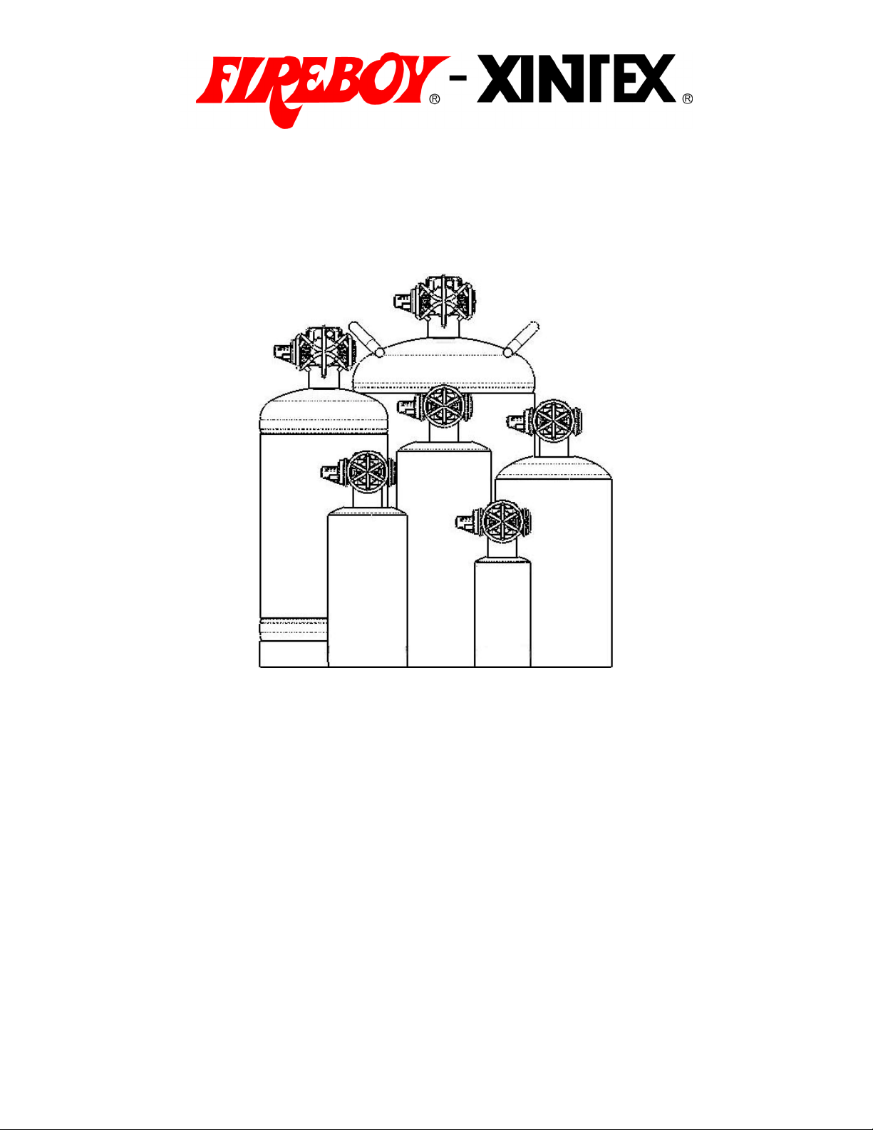
For all sizes 25 cubic feet to 1500 cubic feet
Read and comply with all instructions, warnings
and limitations before installing, servicing or
removing this device.
1
18004
04/03/2007 Rev. C

This owner’s manual and installation instructions pamphlet is provided in English.
Additional copies in English are available at no charge by contacting the
manufacturer, distributor or dealer. Copies in the language of destination are
available upon request for an additional fee. Fireboy-Xintex reserves the right to
change features without notice.
WARNING:
• Do not handle by actuator
• Do not drop
• Keep away from children
• Keep away from extreme heat
• Do not discharge any Fireboy automatic or manual/automatic system
unless securely fastened in accordance with the owner’s manual
• Never attempt to manually discharge a CG2 Fireboy system
• Never attempt to disassemble any component of this system
• Always wear eye, face and body protection when installing, removing or
working in the immediate vicinity of this system
Principle health hazards
• Death without warning if high concentrations are inhaled
• Reduced oxygen available for breathing
• Frostbite from liquid contact
• Increased susceptibility to the toxicity of excess exposure for individuals
with pre-existing diseases of the central nervous system, cardiovascular
system, lungs or kidneys
• Toxic by-products are produced when this agent extinguishes fire
Medical instructions
• If high concentrations are inhaled, immediately move the exposed to
fresh air and keep calm
• If not breathing, give artificial respiration. Seek medical assistance
• If breathing is difficult give oxygen. Seek medical assistance
• In case of skin contact immediately flush skin with water for 15 minutes
• Treat for frostbite if necessary by gently warming affected area. Seek
medical assistance if irritation is present
• In case of eye contact, immediately flush eyes with plenty of water for at
least 15 minutes. Seek medical assistance
• Wash contaminated clothing before reuse
Fireboy FE-241 Systems contain Chlorotetrafluoroethane.
Chlorotetrafluoroethane has been accepted by the EPA as a suitable alternate to
Halon. Fireboy FM Component Approved HFC-227ea Systems contain
Heptafluoropropane. Heptafluoropropane has been accepted by the EPA and
EU as a suitable alternate to Halon. None of the components in these materials
are listed by IARC, NPT, OSHA or ACGIH as a carcinogen.
2

General Information
Fireboy Automatic (CG series) and Manual/Automatic (MA) series Fire
Extinguishing Systems are manufactured for a broad range of applications,
including marine, industrial, and commercial uses. This booklet is intended to
outline the proper installation of the system for marine applications; most
applications are similar. If further technical advice is required, information is
available by writing or calling Fireboy-Xintex.
Fireboy FE-241 Systems are approved for use in unoccupied areas, and are not
approved for use within the European Union.
Fireboy FM Component Approved HFC-227ea Systems are approved for use in
occupied areas and are approved for use within the European Union.
MSDS Sheets are available at no charge from the manufacturer and online at
www.fireboy-xintex.com.
The National Fire Protection Agency defines normally occupied areas as “one
that is intended for occupancy.” (NFPA-2001:20049).
WARNING:
Fireboy systems are not, nor are they intended to be, explosion suppression
devices. They do not lessen the need to inspect for fire hazards and to ventilate
any area where flammable fumes may accumulate.
Referenced Agencies:
Bureau Veritas
3663 N. Sam Houston Pkwy. E., Suite 200
Houston, TX 88034
National Fire Protection Agency
1 Batterymarch Park
Quincy, MA 02269-9101
NFPA 2001, Standard on Clean Agent Fire Extinguishant Systems
FM Approvals
1151 Boston Providence Turnpike
Norwood, MA 02062
United States Coast Guard
2100 Second Street SW
Washington, DC 20593-0001
RINA
10 Upper Belgrave Street
London, SWIX 8BQ
3

WARNING:
• Never install a Fireboy system on the underside of a hatch cover or on
an access door that may open or separate in an explosion
• Never install the actuator of a Fireboy system in close proximity to
exhaust manifolds or turbochargers. Radiated heat may cause
premature actuation
• Never install the actuator of a Fireboy system below the cylinder (Upside
down)
• Never install a Fireboy system where it will trap or be in direct contact
with water
• Never install a Fireboy unit in an compartment larger than its volume
rating
• Never combine the volume rating of two or more Fireboy units to protect
a given compartment
• This device shall not be installed or used in aircraft and/or racing
vehicles
• Diesel powered craft must also install the Automatic Engine Shutdown
system or this system may not extinguish the fire (See Additional
Equipment)
Specifications
When specifications listed on the nameplate label differ from this manual, the
information listed on the nameplate label is correct.
CG2 and MA2 series extinguishers discharge automatically at a temperature of
175°F. MA2 series extinguishers discharge manually at any temperature.
Specification Tables and United States Coast Guard Approval Numbers
Volume Approximate
Protected Diameter Total Height
Model Number ft^3 m^3 in cm in cm lbs kgs lbs kgs U.S.C.G. #
CG2-025-FE241 25 0.71 3 8 9.1 23 0.8 0.4 6 2.7 162.029/175/0
CG2-050-FE241 50 1.4 3 8 12.2 31 1.7 0.8 8 3.5 162.029/176/0
CG2-075-FE241 75 2.1 4.3 11 11.9 30 2.5 1.2 9 3.9 162.029/177/0
CG2-100-FE241 100 2.8 4.3 11 14.5 37 3.4 1.5 12 5.6 162.029/178/0
CG2-125-FE241 125 3.5 4.3 11 14.5 37 4.2 1.9 13 6 162.029/179/0
CG2-150-FE241 150 4.3 5.1 13 13.1 33 5.1 2.3 15 6.9 162.029/180/0
CG2-175-FE241 175 4.9 5.1 13 15.5 39 5.9 2.7 16 7.2 162.029/180/0
CG2-200-FE241 200 5.7 5.1 13 15.5 39 6.8 3.1 17 7.6 162.029/181/0
CG2-225-FE241 225 6.4 6.4 16 14.7 37 7.6 3.5 26 11.6 162.029/181/0
CG2-250-FE241 250 7 6.4 16 14.7 37 8.5 3.8 26 12 162.029/182/0
CG2-275-FE241 275 7.8 6.4 16 14.7 37 9.3 4.2 27 12.4 162.029/182/0
CG2-300-FE241 300 8.5 7.2 18 15.1 38 10.1 4.6 32 14.6 162.029/182/0
CG2-325-FE241 325 9.2 7.2 18 15.1 38 11 5 33 15 162.029/183/0
CG2-350-FE241 350 10 7.2 18 15.1 38 11.8 5.4 34 15.4 162.029/183/0
CG2-375-FE241 375 10.6 7.2 18 17.8 45 12.7 5.8 36 16.2 162.029/183/0
CG2-400-FE241 400 11.3 7.2 18 17.8 45 13.5 6.1 37 16.6 162.029/183/0
CG2-450-FE241 450 12.7 7.2 18 17.8 45 15.2 6.9 38 17.4 162.029/184/0
CG2-500-FE241 500 14.1 7.2 18 24.7 63 16.9 7.7 47 21.3 162.029/184/0
Agent
Weight Shipping Weight
4

Volume Approximate
Protected Diameter Total Height
Model Number ft^3 m^3 in cm in cm lbs kgs lbs kgs U.S.C.G. #
CG2-550-FE241 550 15.6 7.2 18 24.7 63 18.6 8.5 49 22.1 162.029/185/0
CG2-600-FE241 600 17 7.2 18 24.7 63 20.3 9.2 50 22.9 162.029/185/0
CG2-650-FE241 650 18.4 7.2 18 24.7 63 22 10 52 23.6 162.029/185/0
CG2-700-FE241 700 19.8 10 25 21.6 55 23.7 10.8 64 28.9 162.029/185/0
CG2-750-FE241 750 21.2 10 25 21.6 55 25.4 11.5 65 29.7 162.029/185/0
CG2-800-FE241 800 22.6 10 25 21.6 55 27 12.3 67 30.5 162.029/186/0
CG2-850-FE241 850 24 10 25 21.6 55 28.7 13.1 69 31.2 162.029/186/0
CG2-900-FE241 900 25.5 10 25 21.6 55 30.4 13.8 70 32 162.029/186/0
CG2-950-FE241 950 26.9 10 25 21.6 55 32.1 14.6 72 32.8 162.029/186/0
CG2-1000-FE241 1000 28.3 10 25 21.6 55 33.8 15.4 74 33.5 162.029/186/0
MA2-025-FE241 25 0.71 3 8 9.1 23 0.8 0.4 6 2.7 162.029/187/0
MA2-050-FE241 50 1.4 3 8 12.2 31 1.7 0.8 8 3.5 162.029/188/0
MA2-075-FE241 75 2.1 4.3 11 11.9 30 2.5 1.2 9 3.9 162.029/189/0
MA2-100-FE241 100 2.8 4.3 11 14.5 37 3.4 1.5 12 5.6 162.029/190/0
MA2-125-FE241 125 3.5 4.3 11 14.5 37 4.2 1.9 13 6 162.029/191/0
MA2-150-FE241 150 4.3 5.1 13 13.1 33 5.1 2.3 15 6.9 162.029/192/0
MA2-175-FE241 175 4.9 5.1 13 15.5 39 5.9 2.7 16 7.2 162.029/192/0
MA2-200-FE241 200 5.7 5.1 13 15.5 39 6.8 3.1 17 7.6 162.029/193/0
MA2-225-FE241 225 6.4 6.4 16 14.7 37 7.6 3.5 26 11.6 162.029/193/0
MA2-250-FE241 250 7 6.4 16 14.7 37 8.5 3.8 26 12 162.029/194/0
MA2-275-FE241 275 7.8 6.4 16 14.7 37 9.3 4.2 27 12.4 162.029/194/0
MA2-300-FE241 300 8.5 7.2 18 15.1 38 10.1 4.6 32 14.6 162.029/194/0
MA2-325-FE241 325 9.2 7.2 18 15.1 38 11 5 33 15 162.029/195/0
MA2-350-FE241 350 10 7.2 18 15.1 38 11.8 5.4 34 15.4 162.029/195/0
MA2-375-FE241 375 10.6 7.2 18 17.8 45 12.7 5.8 36 16.2 162.029/195/0
MA2-400-FE241 400 11.3 7.2 18 17.8 45 13.5 6.1 37 16.6 162.029/195/0
MA2-450-FE241 450 12.7 7.2 18 17.8 45 15.2 6.9 38 17.4 162.029/196/0
MA2-500-FE241 500 14.1 7.2 18 24.7 63 16.9 7.7 47 21.3 162.029/196/0
MA2-550-FE241 550 15.6 7.2 18 24.7 63 18.6 8.5 49 22.1 162.029/197/0
MA2-600-FE241 600 17 7.2 18 24.7 63 20.3 9.2 50 22.9 162.029/197/0
MA2-650-FE241 650 18.4 7.2 18 24.7 63 22 10 52 23.6 162.029/197/0
MA2-700-FE241 700 19.8 10 25 21.6 55 23.7 10.8 64 28.9 162.029/197/0
MA2-750-FE241 750 21.2 10 25 21.6 55 25.4 11.5 65 29.7 162.029/197/0
MA2-800-FE241 800 22.6 10 25 21.6 55 27 12.3 67 30.5 162.029/198/0
MA2-850-FE241 850 24 10 25 21.6 55 28.7 13.1 69 31.2 162.029/198/0
MA2-900-FE241 900 25.5 10 25 21.6 55 30.4 13.8 70 32 162.029/198/0
MA2-950-FE241 950 26.9 10 25 21.6 55 32.1 14.6 72 32.8 162.029/198/0
MA2-1000-FE241 1000 28.3 10 25 21.6 55 33.8 15.4 74 33.5 162.029/198/0
MA2-1050-FE241 1050 29.7 10 25 21.6 55 35.5 16.1 75 34.3 162.029/199/0
MA2-1100-FE241 1100 31.1 10 25 21.6 55 37.2 16.9 77 35.1 162.029/200/0
MA2-1150-FE241 1150 33 10 25 21.6 55 38.9 17.7 79 35.9 162.029/200/0
MA2-1200-FE241 1200 34 10 25 27.7 70 40.6 18.4 86 38.9 162.029/200/0
MA2-1250-FE241 1250 35.4 10 25 27.7 70 42.3 19.2 87 39.7 162.029/200/0
MA2-1300-FE241 1300 36.8 10 25 27.7 70 60.8 27.7 106 48.1 162.029/201/0
MA2-1350-FE241 1350 38.2 10 25 27.7 70 63.2 28.7 108 49.2 162.029/201/0
MA2-1400-FE241 1400 39.6 10 25 27.7 70 65.5 29.8 111 50.2 162.029/201/0
MA2-1450-FE241 1450 41 10 25 27.7 70 67.9 30.8 113 51.3 162.029/201/0
MA2-1500-FE241 1500 42.5 10 25 27.7 70 70.2 31.9 115 52.4 162.029/201/0
CG2-025-227 25 0.71 3 8 9.1 23 1.1 0.5 6 2.8 162.029/202/0
CG2-050-227 50 1.4 3 8 12.2 31 2.2 1 8 3.7 162.029/203/0
CG2-075-227 75 2.1 4.3 11 11.9 30 3.2 1.5 9 4.2 162.029/205/0
CG2-100-227 100 2.8 4.3 11 14.5 37 4.3 2 13 6.1 162.029/205/0
CG2-125-227 125 3.5 4.3 11 14.5 37 5.4 2.5 14 6.5 162.029/206/0
CG2-150-227 150 4.3 5.1 13 13.1 33 6.5 2.9 16 7.5 162.029/207/0
CG2-175-227 175 4.9 5.1 13 15.5 39 7.6 3.4 18 8 162.029/208/0
CG2-200-227 200 5.7 5.1 13 15.5 39 8.6 3.9 19 8.5 162.029/208/0
CG2-225-227 225 6.4 6.4 16 14.7 37 9.7 4.4 28 12.6 162.029/209/0
CG2-250-227 250 7 6.4 16 14.7 37 10.8 4.9 29 13.1 162.029/209/0
CG2-275-227 275 7.8 6.4 16 14.7 37 11.9 5.4 30 13.6 162.029/209/0
Agent
Weight Shipping Weight
5

Volume Approximate
Protected Diameter Total Height
Model Number ft^3 m^3 in cm in cm lbs kgs lbs kgs U.S.C.G. #
CG2-300-227 300 8.5 7.2 18 15.1 38 13 5.9 35 15.9 162.029/210/0
CG2-325-227 325 9.2 7.2 18 15.1 38 14 6.4 36 16.4 162.029/210/0
CG2-350-227 350 10 7.2 18 15.1 38 15.1 6.9 37 16.9 162.029/210/0
CG2-375-227 375 10.6 7 18 18.8 48 16.2 7.4 38 17.4 162.029/210/0
CG2-400-227 400 11.3 7 18 18.8 48 17.3 7.9 39 17.9 162.029/211/0
CG2-450-227 450 12.7 7 18 18.8 48 19.4 8.8 41 18.8 162.029/211/0
CG2-500-227 500 14.1 7 18 25.7 65 21.6 9.8 47 21.2 162.029/212/0
CG2-550-227 550 15.6 7 18 25.7 65 23.8 10.8 49 22.2 162.029/212/0
CG2-600-227 600 17 7 18 25.7 65 25.9 11.8 51 23.1 162.029/212/0
CG2-650-227 650 18.4 7 18 25.7 65 28.1 12.8 53 24.1 162.029/213/0
CG2-700-227 700 19.8 10 25 21.6 55 30.2 13.7 77 35.1 162.029/213/0
CG2-750-227 750 21.2 10 25 21.6 55 32.4 14.7 79 36.1 162.029/213/0
CG2-800-227 800 22.6 10 25 21.6 55 34.6 15.7 82 37.1 162.029/213/0
CG2-850-227 850 24 10 25 21.6 55 36.7 16.7 84 38.1 162.029/213/0
CG2-900-227 900 25.5 10 25 21.6 55 38.9 17.7 86 39 162.029/214/0
CG2-950-227 950 26.9 10 25 21.6 55 41 18.7 88 40 162.029/214/0
CG2-1000-227 1000 28.3 10 25 21.6 55 43.2 19.6 90 41 162.029/214/0
MA2-025-227 25 0.71 3 8 9.1 23 1.1 0.5 6 2.8 162.029/215/0
MA2-050-227 50 1.4 3 8 12.2 31 2.2 1 8 3.7 162.029/216/0
MA2-075-227 75 2.1 4.3 11 11.9 30 3.2 1.5 9 4.2 162.029/218/0
MA2-100-227 100 2.8 4.3 11 14.5 37 4.3 2 13 6.1 162.029/218/0
MA2-125-227 125 3.5 4.3 11 14.5 37 5.4 2.5 14 6.5 162.029/219/0
MA2-150-227 150 4.3 5.1 13 13.1 33 6.5 2.9 16 7.5 162.029/220/0
MA2-175-227 175 4.9 5.1 13 15.5 39 7.6 3.4 18 8 162.029/221/0
MA2-200-227 200 5.7 5.1 13 15.5 39 8.6 3.9 19 8.5 162.029/221/0
MA2-225-227 225 6.4 6.4 16 14.7 37 9.7 4.4 28 12.6 162.029/222/0
MA2-250-227 250 7 6.4 16 14.7 37 10.8 4.9 29 13.1 162.029/222/0
MA2-275-227 275 7.8 6.4 16 14.7 37 11.9 5.4 30 13.6 162.029/222/0
MA2-300-227 300 8.5 7.2 18 15.1 38 13 5.9 35 15.9 162.029/223/0
MA2-325-227 325 9.2 7.2 18 15.1 38 14 6.4 36 16.4 162.029/223/0
MA2-350-227 350 10 7.2 18 15.1 38 15.1 6.9 37 16.9 162.029/223/0
MA2-375-227 375 10.6 7 18 18.8 48 16.2 7.4 38 17.4 162.029/223/0
MA2-400-227 400 11.3 7 18 18.8 48 17.3 7.9 39 17.9 162.029/224/0
MA2-450-227 450 12.7 7 18 18.8 48 19.4 8.8 41 18.8 162.029/224/0
MA2-500-227 500 14.1 7 18 25.7 65 21.6 9.8 47 21.2 162.029/225/0
MA2-550-227 550 15.6 7 18 25.7 65 23.8 10.8 49 22.2 162.029/225/0
MA2-600-227 600 17 7 18 25.7 65 25.9 11.8 51 23.1 162.029/225/0
MA2-650-227 650 18.4 7 18 25.7 65 28.1 12.8 53 24.1 162.029/226/0
MA2-700-227 700 19.8 10 25 21.6 55 30.2 13.7 77 35.1 162.029/226/0
MA2-750-227 750 21.2 10 25 21.6 55 32.4 14.7 79 36.1 162.029/226/0
MA2-800-227 800 22.6 10 25 21.6 55 34.6 15.7 82 37.1 162.029/226/0
MA2-850-227 850 24 10 25 21.6 55 36.7 16.7 84 38.1 162.029/226/0
MA2-900-227 900 25.5 10 25 21.6 55 38.9 17.7 86 39 162.029/227/0
MA2-950-227 950 26.9 10 25 21.6 55 41 18.7 88 40 162.029/227/0
MA2-1000-227 1000 28.3 10 25 21.6 55 43.2 19.6 90 41 162.029/227/0
MA2-1050-227 1050 29.7 10 25 21.6 55 45.4 20.6 92 42 162.029/228/0
MA2-1100-227 1100 31.1 10 25 21.6 55 47.5 21.6 95 43 162.029/229/0
MA2-1150-227 1150 33 10 25 21.6 55 49.7 22.6 97 43.9 162.029/229/0
MA2-1200-227 1200 34 10 25 27.7 70 51.8 23.6 105 47.7 162.029/229/0
MA2-1250-227 1250 35.4 10 25 27.7 70 54 24.5 107 48.6 162.029/229/0
MA2-1300-227 1300 36.8 10 25 27.7 70 56.2 25.5 109 49.6 162.029/229/0
MA2-1350-227 1350 38.2 10 25 27.7 70 58.3 26.5 111 50.6 162.029/229/0
MA2-1400-227 1400 39.6 10 25 27.7 70 60.5 27.5 113 51.6 162.029/230/0
MA2-1450-227 1450 41 10 25 27.7 70 62.6 28.5 116 52.6 162.029/230/0
MA2-1500-227 1500 42.5 10 25 27.7 70 64.8 29.5 118 53.5 162.029/230/0
Agent
Weight Shipping Weight
6

Marine Installation Instructions
Before Installation
1. Check the system for damage during shipment.
2. Check the pressure gauge to be sure the gauge pointer lies within the
green zone at 70°F (21°C). The correct weight is shown on the
nameplate for the appropriate model.
3. Select an interior location not directly subject to weather or seawater.
4. Confirm the volume of the compartment to be protected in cubic feet or
cubic meters by multiplying the width in feet, by the length in feet, by the
depth at the keel in feet; make no deductions for installed equipment.
5. Verify calculated volume with volume shown on name plate label and
chart on opposite page.
Selecting a Location
1. Do not install a Fireboy system rated for less cubic volume than the
volume of the compartment to be protected.
2. Orientation:
• Mounting up to 90° from vertical is permissible
• Install on the forward or aft vertical bulkhead of the engine
compartment as near the centerline of the vessel (keel) as possible.
• Install as high as possible
• Direct the actuator towards the opposite bulkhead or towards the
engine(s)
• Avoid installing athwart ship (perpendicular to the keel) on sailboats
Mounting Fireboy system
1. Locate the lower bracket 1 ½” above the bottom of the cylinder and the
upper bracket ½” above the Fireboy nameplate. If required the 3
bracket needs to be centered between the upper and lower backets.
2. Use appropriate size and length stainless steel bolts and lock washers
and bolt to bulk head or overhead.
rd
7

Accommodating Diesel Engines
1. Failure to install an Automatic Engine Shutdown in any
compartment containing a diesel engine and a Fireboy system
impedes the fire extinguisher and may prevent fire extinguishment.
2. Automatic Engine Shutdown units are available through your FireboyXintex distributor, dealer or retailer in three, five and eight circuit models.
3. Follow the installation instructions included with the Automatic Engine
Shutdown for proper installation.
4. Technical Support for Automatic Engine Shutdowns is available by
calling Fireboy-Xintex or visiting our website at www.fireboy-xintex.com
Installing Indicator Lamp
Mounting Lamp
1. U.S. Coast Guard regulations require an indicator lamp and escutcheon
plate at each helm position from which the craft may be operated.
2. Your Fireboy System is supplied with one (1) indicator lamp and
escutcheon plate. Additional indicator lamps and escutcheon plates are
available factory direct, or through an authorized dealer (see Additional
Equipment).
3. Select an appropriate location for the indicator lamp and escutcheon
plate on or near the instrument panel at the helm and in full view of the
operator.
4. Drill a 5/16” hole.
5. Remove the backing paper on the escutcheon panel.
6. Feed both wires through 5/16” hole.
7. Press escutcheon plate firmly press in place.
.
8

WARNING:
• An electrical short may result in electrical burn, injury or fire
• Before attempting to wire the indicator lamp, turn off all electrical current
to the ignition switch
• All Fireboy wiring must comply with the American Boat and Yacht
Council Standard E9-9, titled Direct Current Electrical Systems for Boats,
available from ABYC, 3069 Solomon’s Island Road, Edgewater, MD
21037
• The indicator lamp supplied is for 12 VDC use only
Wiring Instructions
1. Review all wiring instructions below.
2. Consult a qualified marine electrician if you have any doubts about your
ability to safely and properly complete the wiring. Ignition systems and
electrical systems vary from boat to boat, and the directions which follow,
may not apply to your boat.
3. Assemble the supplies you will need that are not included with your
Fireboy System.
• The necessary length of insulated 16 gauge (minimum) stranded
wire
• A one-half (.5) ampere in-line fuse and fuse holder or circuit
breaker
• Properly sized insulated crimp-on wire connectors
4. Connect one lead of the fuse to the “ignition” position of the starter
switch.
5. Connect the other lead of the fuse to the red (+) wire of the LED indicator
lamp.
6. Connect the black (-) wire of the indicator lamp to one of the pigtail wires
on the Fireboy System (as shown below).
7. Do not reverse red and black wire, system will not function.
8. Connect the remaining wire from the Fireboy system to ground.
Engine compartments not equipped with a powered ventilation system require no
further wiring.
9

If the engine compartment is equipped with a powered ventilation system, U.S.
Coast Guard Rule 162.029 requires that the ground connection of the ventilation
system be connected to the Fireboy system. Failure to connect a powered
ventilation system in the manner described below impedes fire
extinguisher and may prevent fire extinguishment.
Powered Ventilation Systems (Blowers)
1. Determine the maximum current draw of the powered ventilation
system.
2. For current draw not exceeding 5 amps either:
• Connect the negative (-) wire of the ventilation blower to the pressure
switch at the same point as the indicator lamp, or
• Connect the negative (-) wire of the ventilation blower to the number
1 terminal of a Fireboy Automatic Engine Shutdown system if
available (recommended)
3. For current draw exceeding 5 amps connect the negative (-) wire of the
powered ventilation system to the number (1) terminal of a Fireboy
Automatic Engine Shutdown system.
NOTE:
The Escutcheon plate LED is connected to the pressure switch at the same point
that auxiliary devices can be connected. Care must be taken when wiring other
devices to the pressure switch to ensure the presence of the LED does not affect
the operation of the device. Contact Fireboy-Xintex technical support regarding
any installation questions.
Use of indicator lamp
• The Fireboy System indicator lamp is designed to announce to the
helmsman the state of the fire extinguisher when the ignition key is in the
ON position.
• A GLOWING green light indicates the Fireboy system is CHARGED.
• A NON GLOWING light indicates the Fireboy system is DISCHARGED.
Cable Installation
WARNING:
1. All Fireboy MA Systems installations must use only genuine Fireboy
cables and associated components that are engineered specifically for
this application.
2. Nothing else will provide the intended degree of safety and reliability
inherent in these systems.
3. Any substitution will void all laboratory and Coast Guard approvals and
Fireboy-Xintex warranties, and may result in an inoperative system, and
unsafe and hazardous conditions.
4. Never install a manual release handle in the space to be protected.
5. Never install a cable on a CG2 Series. For use on MA2 Series only.
10

NOTE:
Never push the cable at the T-handle end. Cable may jam and become
inoperable.
Fixing a jammed cable:
1. Turn the T-handle and threaded metal rod counter clockwise ½ turn until
the jam releases.
2. If necessary, use a pair of pliers to carefully twist the threaded metal rod
until the jam releases.
3. Pull the cable from the “S” hook until the cable returns to an operational
position.
4. Do not connect cable to cylinder at this time.
Routing the cable:
1. Locate the escutcheon plate (2 ½” x 4” with 13/32 hole) for the manual
release handle.
• At the helm station
• On a firm support
• In full view of the operator
• With enough clearance for the cable ferrule to extend approximately
12 inches behind the panel
2. Using the escutcheon plate as a template, locate and drill a 13/32” hole.
3. Route the cable in the most direct manner, with as few bends as
possible, to the cylinder location.
• Do not bend in a radius of less than 6 inches (a 12 inch circle)
• Follow the same route as manufacturer installed cables, if possible
(Example: Steering, throttle, and transmission cables)
• Do not subject cable to pinching or crushing, rubbing, extreme
vibration, sharp bending or kinking, or extremes of heat or cold
• Do not exceed 360° of bends (Example: Four 90° bends = 4 x 90° =
360°)
• Use the shortest allowable cable whenever possible
• If excess cable must be coiled; do not coil excess cable in the
protected enclosure
4. Secure loose sections of the cable with the included nylon clamps.
• Do not clamp cable in a bend
• Do not crush cable with clamps
Escutcheon Panel and T-Handle
1. Ensure temperature is above +50°F (10°C) for proper adhesion.
2. Peel the release paper from the back of the escutcheon plate.
3. Align the larger hole with the 13/32 hole drilled in dash.
4. Press escutcheon plate down evenly to activate adhesive.
5. Following figure below, place nut and lock washer in place on the cable
end and insert through the 13/32” hole in the panel and escutcheon.
11

6. Pull cable to full extension.
7. Screw ferrule on to cable (approximately 4-5 turns maximum).
8. Slide o-ring onto cable shaft.
9. Screw red T-handle onto cable shaft (Do not obstruct cross hole in Thandle).
10. Push red T-handle into ferrule to seat o-ring.
11. Align holes in ferrule and T-handle.
12. Temporarily install pull pin.
13. Align T-handle so the word “FIRE” is vertical.
14. Tighten the nut behind the panel.
15. Recheck cable installation.
16. CABLE MUST NOT BE CONNECTED TO CYLINDER AT THIS TIME.
17. Remove pull pin.
18. Pass the red tamper proof seal through the ring of the pull pin and
around the ferrule.
19. Insert the free end of the seal into the projecting portion of the tab end
(marked “enter”).
20. Pull seal snug to secure the pull pin from accidental release.
Dual Release Adapter:
• If the vessel has more than one helm, a Dual Release Adapter , DRA-
1001-01 is required (see Additional Equipment)
• Follow the instructions enclosed with the dual release adapter
Connecting cable to cylinder – See Illustration Below
1. Mount cylinder as described (see Marine Installation Instructions).
2. Insert cable end into the hole in the top of the extinguisher manifold.
12

3. Push the cable end through the hole on the cylinder manifold far enough
to allow the flexible strand to be bent.
4. Place “S” hook through the hole in the MA lever.
5. Gently pull cable sheath back into manifold, aligning the groove in sheath
with slot in the manifold.
6. Insert the wire retaining clip provided around the groove in the cable
sheath through the slot in the manifold securing the cable.
WARNING:
• With the “S” hook attached to the MA lever, and the wire retaining clip
not properly installed, any pull on the cable exceeding 20lbs may actuate
the fire extinguisher
• Never install, remove or service the cable when the fire extinguisher is
not securely mounted in its brackets
• Always wear eye protection while servicing any component of your
Fireboy fire extinguisher
Operation of Fireboy Fire Extinguisher
Automatic operation of CG2 and MA2 systems
• Actuation of a Fireboy fire extinguisher occurs at 175°F (79°C) and is
entirely dependent on the intensity of the fire
Manual operation of MA2 Systems
1. Do not wait for automatic actuation.
2. Close all hatches leading to the protected compartment.
3. Shutdown all forced ventilation devices, engines, generators and
electrical systems.
4. Remove the safety pin from the “FIRE” T-handle, and pull firmly.
Signs of actuation
13

1. A loud sound similar to small arms fire.
2. A loud sound of rushing air.
3. An extinguished indicator lamp.
4. A stalled engine.
When actuation occurs
1. Immediately shutdown all engines, powered ventilation, and electrical
systems.
2. Extinguish all smoking materials.
3. Do not open the engine compartment.
After actuation
1. Before inspecting for damage, allow the agent to “soak” the
compartment for at least 15 minutes and wait for hot metals or fuels to
cool.
2. Have approved portable extinguishers in hand and ready for use.
3. Do not breathe fumes or vapors caused by the fire. They are hazardous
and toxic.
Maintaining Fireboy Fire Extinguisher
1. Inspect the pressure gauge and the system daily.
2. Compare actuator to illustration below to determine if the extinguisher is
ready or discharged.
3. Remove and weigh the complete unit (less brackets) on a certified scale
every six (6) months and record on tag provided.
4. Remove fire extinguisher from service immediately for repair or
replacement if weight is below what is stated on unit’s nameplate (See
Limited Warranty).
Disconnection and Inspection of Manual Discharge Cable
WARNING:
Accidental discharge during handling, installation or inspection may cause
serious injury or death. Wear eye protection when installing or servicing fire
extinguisher or discharge cable.
14

Inspect manual discharge cable annually when inspecting the fire
extinguisher.
1. Do not remove the pull pin on the T-handle when disconnecting the
manual discharge cable from the fire extinguisher manifold.
2. Remove the wire retaining clip securing the cable located at the slot in
the top of the manifold.
3. Carefully push the cable from the backside of the manifold towards the
actuator far enough to allow the flexible center strand to bend.
4. Remove the “S” hook from the black manual actuator lever.
5. Once the “S” hook is free of the lever, pull the cable back and away from
the manifold.
To reconnect the manual discharge cable to the cylinder, refer to “Connecting
Cable to Cylinder” in this manual.
Maintaining the Indicator Lamp Circuit
Should the indicator lamp fail to come ON when the ignition key is ON
1. Check the pressure gauge and actuator to see if the system has
discharged.
2. Check fuse.
3. Using a continuity tester, check the electrical pressure switch on the
system bottle itself:
• Pull the connectors off the spade terminals and place the probes of
the continuity tester directly on the spade connectors
• A closed circuit indicates a functioning pressure switch
4. Check the continuity of the remaining wiring circuit.
5. The indicator lamp is an LED (light emitting diode) and cannot be tested
with a continuity tester. A simple method to test LED’s is to remove the
lamp and touch the Red wire to the + terminal and the black wire to the –
terminal of an ordinary 9 volt battery.
6. Should the continuity of the pressure switch indicate an open circuit, the
system will have to be returned to the factory for either replacement or
repair, depending upon the model involved.
Additional Equipment
Coast Guard Regulation 162.029 requires an indicator lamp be installed at each
helm station from which the vessel may be operated. These additional
escutcheon plates and indicator lamp kits are available factory direct or through
your dealer. Outside the U.S.A. and Canada, see your dealer.
An Automatic Discharge Alarm provides both an audible and visual alarm when
the system discharges. Includes a 2” round instrument with a simple three (3)
wire hookup.
15

Automatic Engine Shutdown/Override System is required for use with Fireboy
systems in diesel powered craft.
Returning Fireboy-Xintex Equipment
No product may be returned for credit or repair without a written “Returned
Material Authorization” (RMA) form. Purchaser must call or email Fireboy-Xintex
616-735-9380 or fireboy@fireboy-xintex.com for a RMA. If due to extenuating
circumstances a product is to be returned, after approval it must be received in
100% new/resalable condition. Products stored by the buyer for more than 26
weeks may not be returned for any reason. Maintaining fresh and current
inventory is the responsibility of the buyer.
Part No. Description
DA-1001-01I Discharge alarm- Round Bezel
DA-1001-02I Discharge alarm- Square Bezel
B-2174-10 Wire Harness for second station display -10'
B-2174-30 Wire Harness for second station display -30'
DRA-1001-01 Permits manual discharge of a Fireboy system from two locations
E-4209-L Manual discharge cable - Specify length (L) in feet
ES-3000-01 3 Circuit engine shutdown system - Round Bezel (12VDC)
ES-3000-02 3 Circuit engine shutdown system - Square Bezel (12VDC)
ES-5000-01 5 Circuit engine shutdown system - Round Bezel (12VDC)
ES-5000-02 5 Circuit Engine shutdown system - Square Bezel (12VDC)
ES-5015-01 5 Circuit engine shutdown system - Time delay -Round Bezel (12VDC)
ES-5015-02 5 Circuit engine shutdown system - Time delay - Square Bezel (12VDC)
ES-8000-01 8 Ciruit engine shutdown system - Round Bezel (12VDC)
ES-8000-02 8 Circuit engine shutdown system - Square Bezel (12VDC)
ES-8015-01 8 Circuit engine shutdown system - Time delay- Round Bezel (12VDC)
ES-8015-02 8 Circuit engine shutdown system - Time delay- Square Bezel (12VDC)
DU-1002-01D Second station display for use with engine shutdown system - Round Bezel (12VDC)
DU-1002-02D Second station display for use with engine shutdown system - Square Bezel (12VDC)
ES-3000-01-24/32 3 Circuit engine shutdown system - Round Bezel (24-32VDC)
ES-3000-02-24/32 3 Circuit engine shutdown system - Square Bezel (24-32VDC)
ES-5000-01-24/32 5 Circuit engine shutdown system - Round Bezel (24-32VDC)
ES-5000-02-24/32 5 Circuit Engine shutdown system - Square Bezel (24-32VDC)
ES-5015-01-24/32 5 Circuit engine shutdown system - Time delay -Round Bezel (24-32VDC)
ES-5015-02-24/32 5 Circuit engine shutdown system - Time delay - Square Bezel (24-32VDC)
ES-8000-01-24/32 8 Circuit engine shutdown system - Round Bezel (24-32VDC)
ES-8000-02-24/32 8 Circuit engine shutdown system - Square Bezel (24-32VDC)
ES-8015-01-24/32 8 Circuit engine shutdown system - Time delay- Round Bezel (24-32VDC)
ES-8015-02-24/32 8 Circuit engine shutdown system - Time delay- Square Bezel (24-32VDC)
ELS-3510-01 3 Circuit engine shutdown system - Low current ignition - Round Bezel
ELS-3510-02 3 Circuit engine shutdown system - Low current ignition - Square Bezel
ELS-5510-01 5 Circuit engine shutdown system - Low current ignition - Round Bezel
ELS-5510-02 5 Circuit engine shutdown system - Low current ignition - Square Bezel
ELS-8510-01 8 Circuit engine shutdown system - Low current ignition - Round Bezel
ELS-8510-02 8 Circuit engine shutdown system - Low current ignition - Square Bezel
16

NOTE:
Detroit Diesel engines may require Automatic Engine Shutdown systems with
time delay.
Fireboy accessories are available from your Fireboy-Xintex distributor, dealer or
retailer.
17

3 YEAR LIMITED WARRANTY
This Warranty is in lieu of all other expressed of implied Warranties
Seller warrants title, materials, and workmanship on equipment, except
components manufactured by others for which the Seller assigns, as permitted,
the original manufacturer’s warranty. Seller’s warranty shall be for a period of (3)
three years from the date of sale to the ORIGINAL CONSUMER PURCHASER,
during which non-conforming equipment returned to the Seller at Buyer’s
expense and risk, be repaired or replaced at the Seller’s option. Fireboy-Xintex,
Inc. will repair or replace products found to be defective in materials or
workmanship within the period set forth above, provided that: (a) the product has
not been subjected to abuse, contamination, neglect, accident, incorrect wiring
not our own, improper installation or servicing, or used in violation of instructions
furnished by Fireboy-Xintex, Inc. and (b) as to any prior defects in materials or
workmanship covered by this warranty, the product has not been repaired or
altered by anyone except Fireboy-Xintex, Inc and (c) the serial number has not
been removed, defaced or otherwise changed, and (d) examination discloses, in
the judgment of Fireboy-Xintex, Inc., does not assume the costs of removal
and/or installation of the product or any other incidental costs of removal and/or
installation of the product or any other incidental costs which may arise as a
result of any defect in material or workmanship, and (e) upon discovery of
defect, Buyer shall immediately cease use of and notify Fireboy-Xintex, Inc.
Any warranty implied by law, including warranties of merchantability or fitness, is
in effect only for the duration of the expressed warranties set forth above, no
person is authorized to give any other warranty, or to assume for Fireboy-Xintex,
Inc. any other liability in connection with the sale of its products; Fireboy-Xintex,
Inc. shall not be liable for the loss of use, revenue, or profit or for any injury, or for
any other consequential or incidental damages, buyer is not relying on seller’s
judgment regarding his or her particular requirements, and has had an
opportunity to inspect the product to his or her satisfaction.
This warranty gives you specific legal rights, and you may also have other rights,
which vary, from state to state.
www.fireboy-xintex.com
P.O. Box 152
Grand Rapids, MI 49501-0152
Phone (616) 735-9380 ● Fax (616) 735-9381
· fireboy@fireboy-xintex.com
O-379 Lake Michigan Dr. NW
Grand Rapids, MI 49534
18
 Loading...