

FireBird Enviromax, Enviromax C80, Enviromax C100, Enviromax C20, Enviromax C26 Technical Manual
...
Working towards a greener planet
TECHNICAL MANUAL INCLUDES
❯❯ HOUSEHOLDER INSTRUCTIONS
❯❯ INSTALLER GUIDE
❯❯ COMMISSIONING
❯❯ SERVICING
❯❯ SPARE PARTS
ENVIROMAX
CONDENSING RANGE
This manual must remain with the householder on completion of installation
TECHNICAL MANUAL
REVISION 6. © 01-03-2010
For use with Diesel 35 Sec. Gas Oil
ROS PRINTERS
TEL: 064-6631233
PROOF

ROS PRINTERS
TEL: 064-6631233
PROOF

Firebird Enviromax Condensing Range
1
CONTENTS
PAGE
Foreword / Introduction 2
1. TERMS & CONDITIONS OF GUARANTEE 3
2. HOUSEHOLDER INSTRUCTIONS
Popular / Boilerhouse ........................................................................................................................ 4
System ................................................................................................................................................................ 4
Systempac ........................................................................................................................................................ 5
Burner Lockout .......................................................................................................................................... 5
3. BOILER TECHNICAL DETAILS
3.1 POPULAR / BOILERHOUSE
Boiler Technical Specifications ..................................................................................................... 6
Wiring ................................................................................................................................................................... 7
Spare Parts ....................................................................................................................................................... 8
Baffles ................................................................................................................................................................... 9
3.2 SYSTEM
Boiler Technical Specifications ...................................................................................................... 10
Wiring ................................................................................................................................................................... 11
Spare Parts ...................................................................................................................................................... 12
Domestic Heating & Hot Water ............................................................................................... 14
3.3 SYSTEMPAC
Boiler Technical Specifications ..................................................................................................... 18
Wiring .................................................................................................................................................................. 20
Spare Parts ...................................................................................................................................................... 21
4. STANDARDS & REGULATIONS
..................................................................................... 23
5. SAFETY
....................................................................................................................................................................... 24
6. INSTALLATION
6.1 Installation Guidelines ........................................................................................................................... 25
6.2 Installation in New Zealand & Australia ............................................................................. 26
6.3 Positioning the Boilers ......................................................................................................................... 27
6.4 Condensate Disposal .............................................................................................................................. 28
6.5 Flue Regulations............................................................................................................................................ 30
6.6 Flue Systems ................................................................................................................................................... 34
6.7 Oil Supply............................................................................................................................................................ 37
7. BURNER
Burner Settings ........................................................................................................................................... 39
Burner Specifications ............................................................................................................................ 40
Fault finding Burner ............................................................................................................................... 41
Spare Parts - Burner ............................................................................................................................. 42
8. SERVICING
............................................................................................................................................. 44
Service Record ............................................................................................................................................ 45
9. COMMISSIONING
..................................................................................................................... 46
ROS PRINTERS
TEL: 064-6631233
PROOF

Firebird Enviromax Condensing Range
2
FOREWORD
We would like to thank you for purchasing a high
efficiency Firebird C Range Condensing domestic
central heating oil fired boiler. This instruction
manual is produced for the reference and
guidance of qualified installation engineers such as
those who are OFTEC registered. EU legislation
governs the manufacture, operation and
efficiency of all domestic central heating oil
boilers. Our boilers and burners will are supplied
as matched units tested and approved to OFTEC
Standard OFS Al00.
FIREBIRD Boilers are full manufacturing members
of OFTEC (Oil Firing Technical Association) and
are participating in its Boiler testing and approvals
programme to comply with OFS A100 and EC
Efficiency Directive.
You should ensure that all installation, servicing
and commissioning works are carried out by a
competent person, such as one registered by
OFTEC. It should be noted that it is the
responsibility of the Installer/Householder to
ensure that the boiler is properly
commissioned. Failure to do so may invalidate
the boiler guarantee and any extended
warranty.
SERVICING
The boiler requires servicing on an annual basis
to ensure it maintains its efficiency, continues
to perform reliably and as a regular check on
its built-in safety features. It is important that
servicing should be conducted by a competent
engineer, such as one who is OFTEC trained
and registered.
All appropriate OFTEC manuals and BS
Standards should be studied and their
requirements adhered to and used in
conjunction with these instructions. This
manual includes a list of some BS Standards
and Building Regulations.
OFTEC is conducting training and registration of
engineers and this is to be commended, as
reading of this manual alone for installation and
servicing procedures cannot replace the critical
advantage provided by training and years of
experience.
INTRODUCTION
Firebird domestic oil fired condensing boilers are
highly efficient and are all independently certified
to Sedbuk Band A. They use less fuel and have
lower running costs than non-condensing boilers.
Because of their increased efficiency they emit
less carbon dioxide than non-condensing boilers,
which will contribute to efforts to reduce global
warming. The incredible efficiency of the Firebird
C Range Condensing Boiler is due to the
development of a single boiler unit with two
unique heat exchanger units. This gives a
exchange surface greater than non-condensing
boilers.
This additional surface area increases the amount
of heat extracted from the combustion process
and thus reduces the heat wasted to atmosphere.
So much heat is extracted from the combustion
gases that their water vapor element condenses
into liquid form, releasing the latent heat that was
used to create the vapor in the first place. It is this
heat gain that gives the condensing boiler its
significant advantage over a non-condensing
model. In order to enable this high level of heat
extraction to take place, the water in the boiler’s
heat exchanger must be cooled down to about
55°C or less, this means that the boiler is working
at its maximum efficiency
The condensate produced is often mistakenly
considered to be highly acidic. In fact the acidity of
condensate from a Firebird C Range Condensing
Boiler will be found to be as low, if not lower, than
that of vinegar.
The Firebird C Range Condensing Boiler is
suitable for under floor heating provided the
return temperature is above 40˚C. at all times.
The Firebird C Range Condensing Boiler even
when not working in condensing mode will still
operate at extremely high efficiencies making it
suitable for fitting to an existing heating system
without alteration to the radiator sizes.
The burner is factory set for use with
kerosene 35 second Gas Oil.
ROS PRINTERS
TEL: 064-6631233
PROOF

Firebird Enviromax Condensing Range
3
TERMS & CONDITIONS OF GUARANTEE
• Firebird boilers are designed and manufactured to give many years of trouble-free
service.We provide a comprehensive conditional warranty of 5 years on the boiler
shell and 2 years on burner and associated controls.
• This will only apply if the boiler is commissioned by an approved engineer and
is serviced annually thereafter.
• Please ensure that the Commissioning Card (the tear-off section on the Guarantee
Card) is returned, fully completed within 28 day’s of complete installation &
commissioning. Correct commissioning will ensure that your boiler is set to
operate at its maximum fuel efficiency.
• Consumable components, the nozzles and the oil hose are excluded.
• The terms laid down on the Guarantee must be adhered to.
1. Firebird hereby guarantees the following
(The Guarantees)
a. The Boiler Shell will be free from defective parts or
workmanship for a period of 5 years from the date of
installation.
b. Burner, controls and flue kits (supplied by Firebird)
will be free from defective parts or workmanship for
a period of 2 years from the date of installation.
(With the exception of burner nozzles, which should
be replaced at the recommended service intervals.)
2. Guarantees are subject to the following conditions:
a. All claims under the guarantees must be within the
above stated time limits.
b. The boiler must be commissioned by qualified
persons and as set out in the Installation Manual,
using correct test equipment.
c. Maintenance should be carried out at the intervals
stated in the Installation Manual.
d. Installation of the boiler must be in accordance with
(a) Installation Manual, (b) all relevant standards and
codes of practice.
e. Firebird can accept no liability in respect of any
defect arising from incorrect installation, negligence,
fair wear and tear, misuse, alteration or repair by
unqualified persons.
f. Firebird will not accept any liability in respect of any
defect occurring in the heat exchanger due to
limescale build-up and or low return water
temperature.
g. The guarantees extend to reasonable labour costs
EXCEPT under clause 1a where any valid claim made
after 3 years will not include labour costs.
h. Firebird’s prior authorisation must be obtained before
examination or repair of the boiler takes place.
i. Firebird will examine all claims made under the
guarantee sand for any claims that are deemed
invalid, the costs incurred will be borne by the
owner.
j. That the appliance was used only for normal
domestic central heating purposes.
3. Any defective part removed under any or all of the
guarantees MUST be returned to Firebird.
STATUTORY RIGHTS OF THE OWNER ARE NOT AFFECTED BY THIS GUARANTEE
1
TERMS OF THIS GUARANTEE
ROS PRINTERS
TEL: 064-6631233
PROOF

Firebird Enviromax Condensing Range
2
4
HOUSEHOLDER
Enviromax System
Operating Procedure
(All outputs)
TO START THE BOILER FOLLOW THIS SEQUENCE:
Turn on fuel supply.
Switch on power supply to boiler.
Turn timer control (If Fitted) to ‘ON’.
Set the boiler thermostat to the required
temperature (figure 1 pg. 5). The boiler thermostat
controls the boiler operation by automatically
maintaining the required boiler water temperature
output. Safe operation is also maintained by the
burner control system which provides the required
ignition and shut off sequence. If a time control is
fitted this will automatically switch the boiler off and
on when heat is required.
THE BOILER C
AN BE TURNED OFF BY
ANY OF THE FOLLOWING MEANS:
Turn the timer control (if fitted) to OFF.
Turn OFF the mains electrical supply to the boiler.
* Lights not included in Utility models.
POPULAR BOILERHOUSE SYSTEM
Enviromax Popular Boilerhouse
Operating Procedure
(All outputs)
TO START THE BOILER FOLLOW THIS SEQUENCE:
Turn on fuel supply.
Switch on power supply to boiler.
Turn timer control (If Fitted) to ‘ON’.
Set the boiler thermostat to the required
temperature (figure 1 pg. 5). The boiler thermostat
controls the boiler operation by automatically
maintaining the required boiler water temperature
output. Safe operation is also maintained by the
burner control system which provides the required
ignition and shut off sequence. If a time control is
fitted this will automatically switch the boiler off and
on when heat is required.
THE BOILER C
AN BE TURNED OFF BY
ANY OF THE FOLLOWING MEANS:
Turn the timer control (if fitted) to OFF.
Turn OFF the mains electrical supply to the boiler.
ROS PRINTERS
TEL: 064-6631233
PROOF
Mains Supply Light *
Burner Lock Out Light *
Burner
Plug
Te mperature
Control
High Limit
re-set button
BURNER
Lock-out
re-set button

figure 1
Set at Max 80˚C Set at Mid 70˚C Set at Min 60˚C
Firebird Enviromax Condensing Range
2
5
HOUSEHOLDER
(ALL MODELS)
The boiler is factory fitted with a burner control box
lockout safety feature which operates automatically if a
fault occurs in the burners operation. Should this occur,
the light on the front of the burner - See Burner Section
Pg. 40 or Boiler Photo - will illuminate and its cause must
be investigated.This could be caused by:
A. An interruption in the fuel supply.
(Eg. empty oil supply tank)
B. An electrical supply fault.
C. A fault with the burner or its safety control system.
D. The failure of a component. (Eg. photo cell)
E. Worn or dirty oil nozzle.
Before attempting to restart the boiler the front panel and
the burner cover should be removed and a visual check
made for any obvious problems such as oil leaks, loose
connections etc.
ENSURE OIL TANK CONTAINS CORRECT GRADE FUEL.
35 SECOND GAS OIL
TO RESTART THE BOILER
1. Press reset button See Burner Section Pg. 40 or
Boiler Photo
2. Ensure that the boiler thermostat, time switch
(if fitted) and any external controls connected to the
boiler are set to call for heat.
3. Check that the oil supply valves and remote sensor
fire valve are open and that there is sufficient oil in
the tank.
4. Check that the burner lockout light is unlit and with
the ‘mains ON’ the boiler will be ready to commence
its start sequence.
SYSTEMPAC
Te mperature Control
BURNER
Lock-out
re-set button
High Limit re-set button
Burner
Plug
Enviromax Systempac
Operating Procedure
(All outputs)
TO START THE BOILER FOLLOW THIS SEQUENCE:
Turn on fuel supply.
Switch on power supply to boiler.
Turn timer control (If Fitted) to ‘ON’.
Set the boiler thermostat to the required
temperature (figure 1 pg. 5). The boiler thermostat
controls the boiler operation by automatically
maintaining the required boiler water temperature
output. Safe operation is also maintained by the
burner control system which provides the required
ignition and shut off sequence. If a time control is
fitted this will automatically switch the boiler off and
on when heat is required.
THE BOILER C
AN BE TURNED OFF BY
ANY OF THE FOLLOWING MEANS:
Turn the timer control (if fitted) to OFF.
Turn OFF the mains electrical supply to the boiler.
Burner Lockout
Thermostat Control
ROS PRINTERS
TEL: 064-6631233
PROOF

Firebird Enviromax Condensing Range
3
6
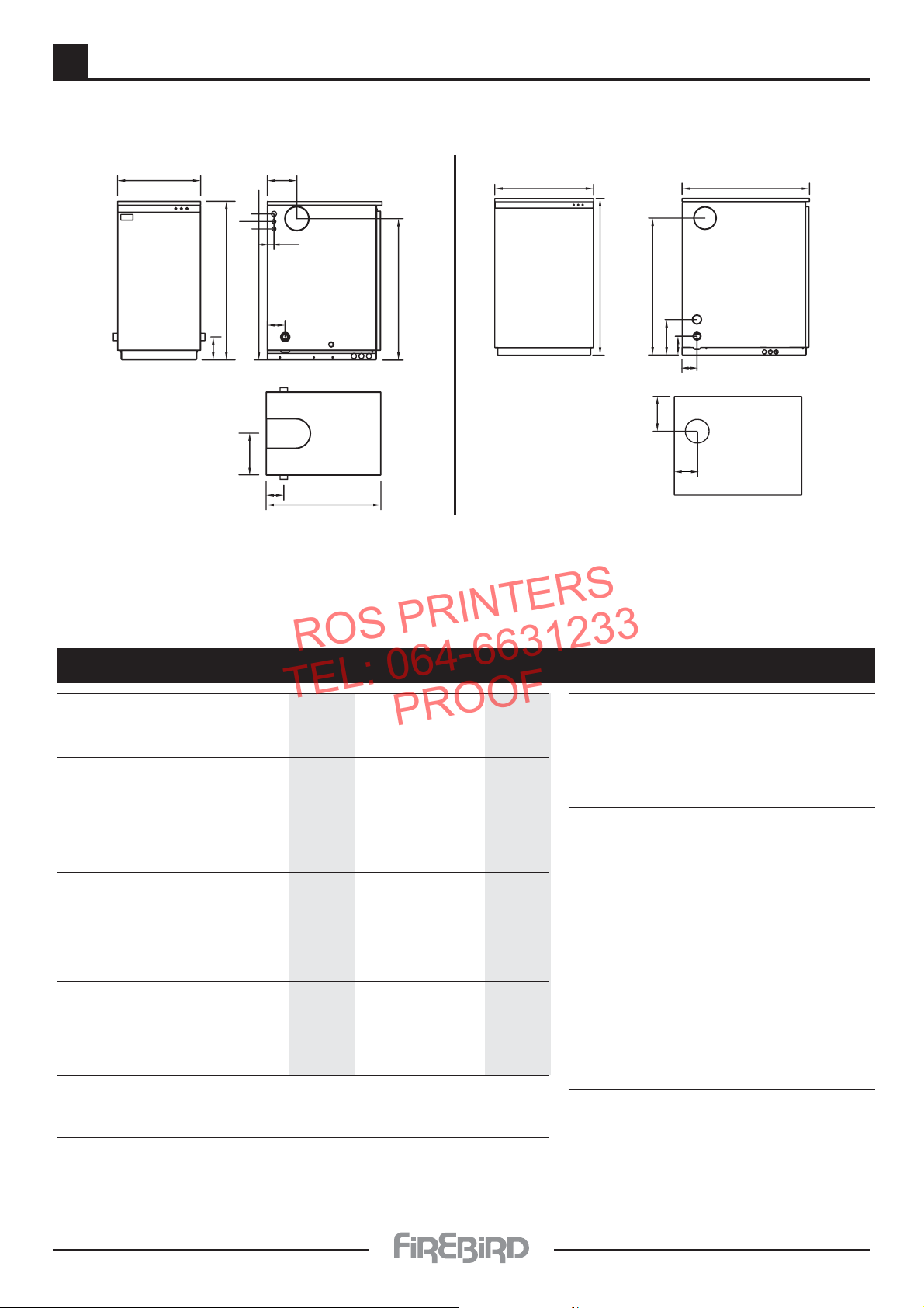
3.1 - POPULAR BOILERHOUSE - TECHNICAL DETAILS
Firebird Enviromax Popular Boilerhouse C Range
Dimensions (mm)
112
705
759
Ø 209
697
130
832
1057
Boiler Model C80 / 100
Max Heat Output Kw 80 / 100
Btu/h (‘000) 341
CONNECTIONS
Heating Flow 2” Bsp.
Heating Return 2” Bsp.
Drain Off Cock 2” Bsp.
Condense Drain Off Connection. 22 mm PLASTIC
WATER CONTENT
Water Content Boiler 75
FLUE (Indoor Boilers) Concentric Flue
Balanced Flue Assembly
(mm) 207 (8”)
Conventional flue Socket. (mm) 207 id.
Flue Draught Reqd.
(Min WG.) 0.040”
Conventional Flue (Max WG.) 0.15”
MAINS WATER SUPPLY Limescale excess: When over 150/200 ppm. Fit appropriate scale reducer.
Pressure Max 10 bar max (Fit pressure reducing valve as necessary)
Min 1 bar min. For user Comfort reduce pressure at tap to between 1 and 5 Bar.
TEMPERATURE CONTROL
Boiler Central Heating Control 60˚C - 80˚C +- 3˚C
Boiler Safety Limit 110˚C +- 3˚C
HEATING SYSTEM (SEALED)
Fit in accordance with BS 7074 Part 1,
BS 5449, OFTEC Standards,etc
Boiler Test Pressure 4.5 Bar
Safety Valve Operating Pressure Gauge 0 to 4 Bar
WATER SIDE RESISTANCE
Flow Rate To Give A Nominal Output At 10k Differential Flow Rate To Give A Nominal Output At 20k Differential
Flow Rate Measured (Kg h
-1
) 2874.24 Flow Rate Measured (Kg h-1) 1522.92
Waterside Resistance
(mbar) 0.18 Waterside Resistance (mbar) 0.19
Pressure Jet Oil Burners RIELLO RDB 4.2
Fuel 35 second Gas Oil
Electrical Supply 230v.AC 50Hz To be fused at 5amp.
Copper Pipe Not Plastic to be used for a minimum of 1 metre off the boiler
ROS PRINTERS
TEL: 064-6631233
PROOF

Firebird Enviromax Condensing Range
3
3.1 - POPULAR BOILERHOUSE - WIRING
ELECTRICAL SUPPLY
The boiler and controls require 230V 1 phase 50Hz mains electric supply protected with a 5amp fuse.
The guarantee on this product will be rendered void if damaged by power from a stand by electricity supply. i.e. (Generator.)
THIS APPLIANCE MUST BE EARTHED.
A qualified electrician must carry out all electric wiring in accordance with current I.E.E Regulations and any local
regulations which may apply.
The mains electrical supply must be taken from a double pole isolating switch with a 5amp fuse, positioned somewhere
close to the boiler.Heat resisting cable must be used which can be routed into the boiler through the access provided on
either side of the base. Ancillary controls may be provided for with terminal connections in the control panel.
Burner Plug.
N
E
Burner Plug.
Safety Limit
Thermostat.
Reset Pin Inside
Screw Off Cover.
Temperature
Controll Dial.
MAX.
MIN.
X = Burner Lock out.
N = Neutral.
L = Live
= Earth
Normally Open Contacts
Close On Rising Temp
TIME-SWITCH
FROST THERMOSTAT
MAINS IN
OVER RUN DIAGRAM FOR CIRCULATING PUMP.
Normally Closed
Contacts Open
On Rising Temp.
Clamp on pipe stat Set at 87˚C.
N.
TWO POLL SWITCH
(SERVICE SWITCH)
PUMP
HEATING
UNIT
N.
L
NX
L
NX
Control Thermostat.
Safety Limit
Thermostat.
E
E
Use Double Insulated
Heat ResistantCable.
Power supply
to Burner.
When connecting the mains
supply to this unit ensure that:
1 Double insulated heat resistant cable is
used.
2 No single insulated cable is exposed at
connection points on the (Therrmostat,
Burner, plug and socket)
3 All relevant lids and covers are properly
replaced and secured correctly.
4 A permanent power supply (not timed)
be available at location of boiler.
This can be used for a frost thermostat
and or an over heat thermostat, should
either or both be needed.
TO RESET: Wait for temperature to drop, unscrew cap then depress red pin.
Safety Limit
Thermostat.
Live Out To
Burner / Boiler.
Control
Thermostat.
= Earth
Burner Lock out.
Neutral.
Burner Lock out.
Switch Live
Neutral.
= Earth
SCHEMATIC DIAGRAM.
IMPORTANT
I. Stat Dual Thermostat
= Earth
L = Live
N = Neutral.
X = Burner Lock out.
POPULAR / BOILERHOUSE WIRING
Common.
CONTROL STAT. & LIMIT STAT.
Not Required in
Boilerhouse or
Heatpac Models
7
ROS PRINTERS
TEL: 064-6631233
PROOF

Firebird Enviromax Condensing Range
3
8
3.1 - POPULAR BOILERHOUSE - PARTS
ROS PRINTERS
TEL: 064-6631233
PROOF
4
15
5
3
5
4
3
2
1
1. Frame 2. Cone 3. Float
4. Screw Cap 5. Connector
2
1
6
14
13
10
11
12
ENVIROMAX POPULAR - Boilerhouse Model C100
No. Description C100
1 Burner panel 212416
2 Right Side Panel 212415
3 Left Side Panel 212418
4 Back Panel 212417
5 Jacket 112421
6 Shell 7 Burner 410210
10 Graphite Door Seal 112414
11 Door Gasket 112362
12 Boiler Door 212423
13 Condense Trap 112184
14 Condensate Hose 111537
15 Boiler Dual Thermostat 112018

Firebird Enviromax Condensing Range
3
9
3.1 - POPULAR BOILERHOUSE BAFFLES
• • • • PATENTED BOILER DESIGN • • • •
ENVIROMAX (E) RANGE BAFFLES.
Tube Baffle (4 Off) E26 & E35 - Part No. 110907
E26 & E35 Door. - Part No. 210910
E26 & E35 Door Gasket. - Part No. 110918
Tube Baffle (1 Off) E26 & E35 Part No. 110908
Tube Baffle (4 Off) E26 & E35 - Part No. 110909
E26 Smoke Baffle R4 ............... - Part No. 212028
E35 Smoke Baffle oblong ...... - Part No. 212122
ENVIROMAX C26 & C35
ENVIROMAX C44, C58, C73 & C100
ROS PRINTERS
TEL: 064-6631233
PROOF
8 No. C44 Gas Baffle.
Part No. 211651.
8 No. C58 Gas Baffle. Part No. 211640.
8 No. C73 Gas Baffle. Part No. 211501.
8 No. C100 Gas Baffle. Part No. 212429
8 No. Gas Baffles.
C44/C58 Graphite Seal. Part No. 111646.
C73 Graphite Seal. Part No. 111511.
C44/C58 Duroboard Door. Part No. 111645.
C73 Duroboard Door. Part No. 111506.
C44 - C58 Baffle Door. Part No. 211644.
C73 Baffle Door. Part No. 111505.
Tube baffle No.3
Part No. 211504.
8 No. Tube baffle No. 1
Tube baffle No.1
Part No. 211502.
C100 Tube Baffle
Part No. 112502
C44 & C58
C73
5 No. Tube baffle No. 36 No. Tube baffle No. 1
Tube baffle No.2
Part No. 211503.
6 No. Tube baffle No. 2
4 No. Tube baffle No. 2
C100 - 10 x Tube baffle No. 1 • 9 x Tube baffle No. 2
Firebird Enviromax Condensing Range
3
10
3.2 - SYSTEM
Firebird Enviromax System C Model
Dimensions (mm)
Model Output Weight Dimensions(mm)
Enviromax Kw/hr kg H W D A B C E F G
System C20 143 845 442 610 753 221 157 94 124 System C26 146 845 442 610 753 221 157 94 124 System C35 149 845 442 610 753 221 157 94 124 System C44 235 1046 660 852 914 232 157 100 125 236
System
C44
System
C20 - C35
E
Top View
H
W
D
A
F
C
B
E
40
40
695
35
Front View Side View
Front View Side View
w
H
D
A
G
F
E
B
C
To p V ie w
Copper Pipe Not Plastic to be used for a minimum of 1 metre off the boiler
Boiler Model C20/26 C35 C44
Max Heat Output Kw 20/26 35 44
Btu/h (‘000) 68/89 119 150
CONNECTIONS
Heating Flow 1” Bsp 1”Bsp 1
1
/
2
” Bsp
Heating Return 1” Bsp 1”Bsp 1
1
/
2
” Bsp
Drain Off Cock
1
/2” Bsp.
1
/2” Bsp.
1
/2” Bsp.
Safety Pressure Relief valve outlet (Copper)
1
/2” Bsp.
1
/2” Bsp.
1
/2” Bsp.
Condense Drain Off Connection.
3
/4” Bsp. Female
Circulating Pump (Grundfos) 25/60 25/60 25/80
Boiler integral Expansion 12 litres 12 litres 18 litres
Vessel Normal Capacity pre-charged to 1 bar.
WATER CONTENT
Water Content Boiler 24 24 45
FLUE (Indoor Boilers) Concentric Flue
Balanced Flue Assembly
(mm) 125 (5”) 125 (5”) 155 (6”)
Conventional flue Socket.
(mm) 130 id. 130 id. 155 id.
Flue Draught Reqd.(Min WG.) 0.040” 0.040” 0.040”
Conventional Flue (Max WG.) 0.15” 0.15” 0.15”
Pressure Jet Oil Burners RIELLO RDB 2.2 up to C35 & RIELLO RDB 4.2 up to C58 - C73
Fuel 35 second Gas Oil
Electrical Supply 230v.AC 50Hz To be fused at 5amp.
TEMPERATURE CONTROL
Boiler Central Heating Control
60˚C - 80˚C+- 3˚C
Boiler Safety Limit 110˚C +- 3˚C
Tank (DHW)- Fixed 78˚C +- 3˚C
Early Alert - Fixed 87˚C +- 3˚C
Over-run - Fixed 93˚C +- 3˚C
HEATING SYSTEM (SEALED)
Fit in accordance with BS 7074
Part 1, BS 5449,OFTEC Standards, etc
Max. Operating Pressure 2.5 Bar
Max. System Pressure cold 1.5 Bar
Min. System Pressure cold 0.5 Bar + 0.3 Bar
Boiler Test Pressure 4.5 Bar
Safety Valve Operating Pressure 3 Bar
WATER SIDE RESISTANCE
Flow Rate To Give A Nominal Output At 10k Differential
Flow Rate Measured (Kg h
-1
) 2874.24
Waterside Resistance (mbar) 0.18
Flow Rate To Give A Nominal Output At 20k Differential
Flow Rate Measured (Kg h
-1
) 1522.92
Waterside Resistance (mbar) 0.19
Guidelines for Sealed System Installation - See section 3.2, 4, 5 & 6
ROS PRINTERS
TEL: 064-6631233
PROOF

Firebird Enviromax Condensing Range
3
11
3.2 - SYSTEM - WIRING
ELECTRICAL SUPPLY
The boiler and controls require 230V 1 phase 50Hz mains electric supply protected with a 5amp fuse.
The guarantee on this product will be rendered void if damaged by power from a stand by electricity supply. i.e. (Generator.)
THIS APPLIANCE MUST BE EARTHED.
A qualified electrician must carry out all electric wiring in accordance with current I.E.E Regulations and any local regulations
which may apply.
The mains electrical supply must be taken from a double pole isolating switch with a 5amp fuse, positioned somewhere close
to the boiler.Heat resisting cable must be used which can be routed into the boiler through the access provided on either
side of the base. Ancillary controls may be provided for with terminal connections in the control panel.
ROS PRINTERS
TEL: 064-6631233
PROOF
Firebird Enviromax System Wiring Diagram
Enviromax 7 Pin Plug Wiring White Panel with Lights & Pressure Switch
Power To
Burner
Firebird
Dual Thermostat
Temperature
Control Dial.
High Limit
Thermostat.
Reset Pin Inside
Screw Off Cover.
MAX.
Control
Thermostat.
MIN.
Safety Limit
Thermostat.
Control Thermostat.
L1
N
L2
E
E
L
N
X
N
Pressure
LX
Switch.
T2
B4
B3
C
Pump Over run
Thermostat. 87˚C.
2
1
L1
N
T1
Temperature
Control.
Max 80˚C.
MIN. MAX.
Min 60˚C.
MIN. MAX.
Pressure Gauge.
Burner Plug.
Connection.
(B4) NEUTRAL
(S3) EARTH.
Mains
B4
S3
T1
T2
PERMANENT
LIVE (T1)
TIMED
SWITCH LIVE (T2)
B4
T2
S3
L1
T1
N
Pump
Connection.
N
NEUTRAL (N)
L1
PUMP LIVE (L1)
EARTH.
Use Heat Resistant Cable. Protect Supply with 5 Amp. Fuse.
Not in Use.
Burner Lock Out Light.
Mains Supply Light.
High limit
re-set button.
7 Pin Plug.
Power Supply & Pump.

Firebird Enviromax Condensing Range
3
12
3.2 - SYSTEM - PARTS
ROS PRINTERS
TEL: 064-6631233
PROOF
7
11
8
5
6
16
12
14
13
3
ENVIROMAX SYSTEM - White Cased Models C20, C26, C35 & C44
No. Description C20 / C26 / C35 C44
1 Front Panel 111376 111787
2 Front Panel Insulation 110937 111788
3 Left Side Panel 111374 111786
4 Right Side Panel 111374 111792
5 Top Panel 111375 111793
6 Top Panel Insulation 111794 111789
7 Flue Trim (Half Moon) 111397 111587
8 Flue Blank 111388 111586
9 Flue Gas Analysis Blank 110923 110923
10 Control Panel 311671 311706
11 Back Support 111596 111790
12 Insulation Jacket 110917 111653
13 Boiler Shell 310960 311783
14 Left Support Bracket 210915 211805
15 Right Support Bracket 210915 211797
16 Back Support Bracket 210916 211770
17 Burner C20 410205 C44 410208
C26 410206 C58 410209
C35 410208
18 Air Hose 111902 111902
19 Pressure Vessel Bracket 210962 210962
15
9
4
18
17
19
10
2
1

Firebird Enviromax Condensing Range
3
13
3.2 - SYSTEM - PLUMBING PARTS
ROS PRINTERS
TEL: 064-6631233
PROOF
8
15
7
1
16
7
6
9
2
1
12
10
11
14
6
12
11
10
7
2
13
9
1
ENVIROMAX SYSTEM PLUMBING PARTS
No. Description C20 / C26 / C35 C44 / C58
1 12ltr. Pressure Vessel ACC 012PVL ACC018PVL
2 Expansion Vessel Hose ACCCOMHOS ACCCOMHOS
6 Auto Air Vent ACCCOMAAV ACCCOMAAV
7 Pressure Switch ACC000PSW ACC000PSW
8 22mm Pump Valve ACC022PIV ACC022PIV
9 Circulating Pump ACCCOMPMP ACC150PMP
10 Pressure Gauge ACCCOMPRG ACCCOMPRG
11 3 Bar Safety Valve ACCCOMSRV ACCCOMSRV
12 Manual Air Vent ACCCOMMAC ACCCOMMAC
13 1
14 System Pipe 1 110969 15 System Pipe 2 110970 16 System Pipe 3 110971 17 22mm Butterfly Valve - -
1
/4”Gate Valve - 110758

Firebird Enviromax Condensing Range
3
14
3.2 - DOMESTIC HEATING & HOT WATER
When the system is cold and filled to initial fill pressure
Pithe pointer on the pressure gauge should point at 1
bar.
The pressure gauge shown has two red zones marked
on it. The first is between 0 and 1/2 a Bar. If the pointer
falls into this zone when system and boiler are cold this
is indicating that initial System Fill Pressure has
dropped and this will activate the pressure switch
cutting off power supply to the Combi C. Refill system
manually until indicated pressure rises to 1 bar.
N.B. Insufficient pressure in the boiler will cause
power supply to switch off.
* A 12 litre expansion vessel is fitted to boiler,
precharged with air or nitrogen to 1 bar which allows
a system static head of 5 metres. If the static head is
greater than this then the air charge in the vessel must
be increased to balance the higher static head. The air
charge should not exceed a pressure of 1.5 bar.
The Firebird Combi C Boiler’s with built in
Expansion Vessels having an initial air charge
pressure of 1 bar. If total water content of system is
greater than the capabilities of the vessel supplied
then an additional vessel will be required to be
fitted to the return pipe as close as is practical to
the boiler.There should be no valves or restrictions
between vessel and boiler. See page 17 for vessel
sizes.
If static head is altered then it is also necessary to alter
air charge pressure to equal static head (+ 0.3 Bar).This
is necessary in order to keep system water from
entering expansion vessel until system is being heated
and thus allow its maximum acceptance volume (V) to
be used only to accommodate the expansion of
system water during boiler operation.
Remember that air charge pressure must be equal in
both vessels (attached to the same system). In the
above example this is 1 bar. Air charge pressure is the
air pressure in expansion vessel before system is filled.
It is measured with a tyre gauge attached to Schrader
valve on the vessel.
SEALED HEATING CIRCUIT
(also applies to System Boilers)
The system must comply with BS 7074 Part 1 and BS
5449 Part 1 with a maximum water temperature of
80˚C.
* A manual reset overheat limit thermostat is located
at the rear of the electrical control panel. If a boiler
overheat condition arises the burner will stop and
remain inoperative until this thermostat reset
button is depressed.
* A pressure relief valve to BS 6759 operating at 3 bar
(45 lb/in
2
) is fitted. A discharge pipe of 15 mm
diameter is also fitted to the discharge connection
on the pressure relief valve. During installation an
extension pipe should be fitted to this, leading, to
outside the building.The pipe should be as short as
possible and may need a tundish fitted in a
protected position within the building.
Note:- Water must not discharge above an
entrance, window or where public have access.
The installer must be aware that the discharge
may be boiling water.
* A drain cock must be fitted at the lowest points in
the system to enable draining as necessary. A drain
cock is already fitted at the bottom of the boiler heat
store to enable draining of boiler and tank unit only.
All pipes connected to boiler should have shut off
valves fitted to facilitate this.
* A Pressure gauge, having range 0 to 4 bar is fitted to
boiler control panel.This indicates water pressure in
boiler and system at time of reading. Pressure
when cold should be
1
/2bar minimum to 1.5 bar
maximum. This is known as Initial System Design
Pressure (Pi).
N.B. Initial System Design Pressure (measured in
bar) equals static head of system (measured in bar)
plus 0.3.
ROS PRINTERS
TEL: 064-6631233
PROOF
Firebird Enviromax Condensing Range
3
15
3.2 - DOMESTIC HEATING & HOT WATER
N.B. The second red zone is between 21/2 and 4 bar
pressure. When the heating system is up to full
working temperature, if the pointer on the
pressure gauge should enter this red zone
showing a final system design pressure of more
than 2
1
/2 bar, it is likely that:
(a) Total system water content is greater than
that calculated and if additional expansion
vessel has been fitted it should be replaced
with a larger unit
OR if integral boiler expansion vessel only is
used then an additional expansion vessel is
required.
(b) Static head may be higher than calculated. In
this case it is necessary to re-measure static
head and revise expansion vessel air charge
pressure.
(C) Expansion vessel incorrect size or air charge
pressure incorrect.
Refer to BS 7074
Part 1 and BS 5449 for further information.
EXAMPLE: using above table
If total water content of system is - 150 litres
and initial system pressure required is - 1.0 bar
then vessel volume required is - 16.3 litres
[from above table]
The vessel supplied with boiler is - 12.0 litres
therefore an additional vessel of - 4.3 litres
is required
(minimum)
(For this system of 150 litres - total water volume)
..Nearest available stock size for additional vessel
required, at 1 bar initial system pressure (taken from
above table) is 5 Litres.
It is emphasised that the installer should be fully
acquainted with sealed system installation and
operation, calculation of total system water volume,
determining of initial system pressure required and
calculation of any additional expansion vessel volume
required. Warranty is void when the boiler is
installed in a system with insufficient expansions.
NB .. Ensue that all expansion vessels in the same
system are set at EQUAL air charge pressures.
Safety Valve Setting 3 bar
Initial System Pressure 0.5 bar 1.0 bar 1.5 bar
Total Water Content TOTAL VESSEL
of System VOLUME **
Litres Litres Litres Litres
25 2.1 2.7 3.9
50 4.2 5.4 7.8
75 6.3 8.2 11.7
100 8.3 10.9 15.6
125 10.4 13.6 19.5
150 12.5 ->[16.3]<- 23.4
175 14.7 19.1 27.2
200 16.7 21.8 31.2
225 18.7 24.5 35.1
250 20.8 27.2 39.0
FOR FURTHER INFORMATION CONSULT
APPROPRIATE TRAINING MANUALS
AND BS 7074 PART 1, BS 5449, ETC
* * When calculating size of any additional
expansion vessel required,remember to deduct
the boiler expansion vessel volume of 12 litres
from the calculated total system vessel volume
required, as given in above table.
EXPANSION VESSEL AND SYSTEM
REQUIREMENTS
DOMESTIC HOT WATER CIRCUITS
The final 600 mm mains water supply should be of
copper tube to BS 2871 Part 1. Ensure that any capillary
fittings used are of lead free solder variety.
For user comfort the mains pressure at taps should
be between I and 5 bar. If it exceeds this it is
advisable to fit a pressure reducing valve adjusted
to reduce pressure to an acceptable level within
above range.
To ensure user comfort and satisfaction it may be
advisable to discuss foregoing with householder.Where
long hot water supply-pipe runs are used these should
be insulated to prevent rapid cooling of residual hot
water after draw off is completed.
If the boiler is fitted in a hard water area check that
hardness does not exceed 150 p.p.m. by testing with a
standard test strip. Immerse test strip in flowing tap
water for one second. Shake off excess water. Check
strip after approximately fifteen seconds. If three or
more zones have changed colour the water hardness is
over 150 p.p.m. (Read instructions on test strip
package). Fitting of an in line scale inhibitor is then
necessary.
Failure to check water hardness and fit appropriate
water softening equipment will result in scale build
up and consequent reduction in water heating
performance. Check with local Water Authority if in
doubt.
ROS PRINTERS
TEL: 064-6631233
PROOF

Firebird Enviromax Condensing Range
3
16
3.2 - DOMESTIC HEATING & HOT WATER
Hot and Cold taps, mixing valves and fittings must be
suitable for operating at mains pressure up to 10 bar
Bidets with the supply of hot and cold mains water are
permitted if they are of the over-rim flushing type and
have shrouded outlets which enable them to have
temporary hand held spray attached. Showers of loose
headed or flexible type must be fixed so that the head
cannot fall closer than 25mm above the top edge of the
bath to prevent it immersing into the bath water.
Alternatively the shower should have a double check
valve incorporated at the point of the flexible
connections.
WATER FLOW REGULATION
The flow rate of water from individual taps may be
affected by any of the following:-
1. Number of taps in use at one time
2. Cold mains pressure
3. Diameter and length of pipework in the
domestic water circuits within the dwelling.
4. Excessive flow from 3/4” bath taps in a house
system converted to mains water supply.
It is recommended:A. To ensure that the mains water connection to
the appliance is the first connection from
the mains on entering the dwelling.
B. Where flow starvation is encountered that flow
restrictors or balancing valves are fitted
at supply outlets.
* The boiler has circulating pumps fitted therefore no
other is normally required. They are factory set at
maximum output.This setting should not be altered
on the domestic hot water pump as production of
domestic hot water may be adversely affected.
SYSTEM FILLING,TESTING AND MAKE-UP
Introduction
Mains cold water is supplied through the boiler
pipework to two separate circuits operating at different
pressures.
Circuit One
This is the Radiator Heating System including boiler
and primary tank which is filled from mains supply via
flex filling loop (see - Method A) within boiler to a
pressure determined from system static head,
expansion vessel size and system water volume. This
flexible filling loop should be disconnected when
boiler and system are filled and checked, See
diagrams - Method A & Method B).
Circuit Two
This is the domestic cold water supply through the
boiler plate heat exchanger via domestic hot water
pipework direct to hot taps. This works at full mains
pressure or if this is excessive at a reduced pressure
controlled by a mains pressure reducing valve to a
pressure acceptable to householder and satisfactory for
the correct operation of Combi C Boiler System.This
mains pressure reducing valve is not supplied with
boiler, but will be available from a local supply
merchant.
System filling should take place slowly and can
be done by either of the following methods:-
Manual Filling
The Firebird Combi C comes with this system built into
the appliance. It consists of a flexible hose connection
with a butterfly shut off valve at each end and a double
check valve assembly at boiler end. To conform to
requirements of BS 7074 Part I and local water Authority
Bye Laws, the flexible hose should be disconnected at
one end when filling has been completed and checked.
Two end caps are supplied and should be fitted to
disconnected ends as a safety precaution against
inadvertent opening of ball valves.
Pressure gauge on Control Panel should be checked
occasionally when system is cold. Refill to initial fill
pressure if necessary. Should this be a frequent
occurrence, complete system should be checked for
leaks.
Automatic Filling
Automatic System filling may be made with a feed and
make-up cistern connected through a double check
valve and stop valve assembly to the return side of the
heating system as close to the boiler as is practical.This
cistern should be located above the heating systems
highest point to give a minimum static head of 300 mm
between it (highest point) and cistern. The manual
filling system fitted to boiler should then be
disconnected and connection points blanked off.
This system has the advantage of automatic water
make-up in the event of system pressure loss due to air
elimination and minor leaks. In any case control panel
pressure gauge should be occasionally checked.
METHOD A.
Mains
Water
Supply
Filling
Direction
Double
Check Valve
Hose
Union
Heating
Circuit
Return
Stop
Valve
Test Clock.
Disconnect After Filling
Filling
Direction
ROS PRINTERS
TEL: 064-6631233
PROOF

Firebird Enviromax Condensing Range
3
17
3.2 - DOMESTIC HEATING & HOT WATER
N.B. Remember also to check air fill pressure of
Expansion Vessel when system is cold
using standard tyre gauge connected to
Schrader air valve on vessel.
NOTE: There shall be no direct connection to the
mains, even with the use of a non-return
valve without the permission of Local
Water Authority.
* It is recommended that an inhibitor be added
at the time of final fill to protect the System
from corrosion. Ensure that this is carried out
in accordance with inhibitor manufacturers
instructions. Installer should ensure that
inhibitor used is suitable and that it will have
no adverse effect on Expansion Vessels
diaphragms or any other part or component
of the system.
COMMISSIONING
* Before proceeding to filling, ensure that
electricity supply is switched off at mains to
avoid any possibility of time switch operating
and passing power to appliance prior to filling.
Filling and Testing
Check that all connections, especially compression
joints, are fully tightened. Re-check and ensure that
pressure vessel air charge is correct, then fill system
with water via filling system used. Turn off water
supply before system pressure reaches safety valve
operation point of 3 bar. (Say 2 to 2.5 bar).Vent system
via all manual air vents including circulating pumps,
boiler,radiators,system high points. etc.Check that dust
caps are loosened on auto air vents, keep constant
check on system pressure gauge (fitted to control
panel). If pressure has dropped re-admit water to above
pressure. Ensure all appropriate boiler and system
valves are open.
METHOD B
-With water supply turned off, thoroughly flush out
boiler and system to remove all foreign matter before
allowing boiler and pumps to operate. If in doubt drain
system and repeat above procedure. At this stage
flushing-out water should be clean and clear of all
foreign matter.
Refill the system and again vent at all points as
described above. Examine the complete system for
water leaks having pressurised it to 1 - 2.5 bar. Correct
any leaks, then check operation of safety valve by
admitting further water until this valve operates. This
should occur when system pressure rises to between
2.7 and 3.3 bar.When satisfied with valve operation, and
with mains water still turned off, draw off sufficient
water until initial system design fill pressure (Pi). (cold
fill) is established (0.5 - 1 bar - as calculated for system).
Remember that initial cold fill pressure can only be
checked when system water has properly cooled down.
Check that final operating pressure (Pf) is under 2.5
bar with all radiators turned on and up to highest
working temperature. Should system operating
pressure exceed this,check:
1. That initial cold fill pressure is correct and , if
additional expansion vessel is fitted, that
pressure is equal in each vessel.
2. That expansion vessels are sized correctly.
Special attention should be given to existing
heating systems where Firebird Combi C boiler has
replaced an existing unit. Extra effort should be
made to ensure that all original pipe work and
radiators are repeatedly flushed. If possible use a
proprietary cleansing agent suitable for system as
loosened scale and foreign matter can seriously
reduce domestic hot water performance and pump
efficiency.
Use corrosion inhibitor of suitable type.
ROS PRINTERS
TEL: 064-6631233
PROOF

Firebird Enviromax Condensing Range
3
18
3.3 - SYSTEMPAC
Firebird Enviromax Heatpac C Range
Dimensions (mm)
SYSTEMPAC & HEATPAC
SLIMLINE HEATPAC
Model Output Weight Dimensions(mm)
Enviromax Kw/hr kg H W D
Slimline C26 150 922 756 469
Slimline C35 153 922 756 469
Model Output Weight Dimensions(mm)
Enviromax Kw/hr kg H W D A B C E F G I J K N P
Heatpac C26 158 946 713 622 808 179 540 176 432 134 271 79 45 ø46 70
Heatpac C35 158 946 713 622 808 179 540 176 432 134 271 79 45 ø46 70
Heatpac C44 244 1074 840 856 936 181 684 176 796 134 507 85 40 ø63 115
D
H
W
A
B
C
E
F
IG
I
JK
N
P
ø28
68
C35
520
710
600
ø16
430
172
620
194
108
D
W
H
116
143
100
473
119
45
45
67
126
ø46
ø28
445
115
ø28
126
ø88
805
Firebird Enviromax Slimline C Range Dimensions (mm)
Copper Pipe Not Plastic to be used for a minimum of 1 metre off the boiler
ROS PRINTERS
TEL: 064-6631233
PROOF

Firebird Enviromax Condensing Range
3
19
3.3 - SYSTEMPAC
ENVIROMAX Systempac Heatpac / Slimline Heatpac
Boiler Model C26 C35 C44 C26 C35 C44/58 C73
Max Heat Output Kw 26 35 44 26 35 44 / 58 73
Btu/h (‘000) 89 119 150 89 119 150 / 198 249
CONNECTIONS
Heating Flow 1” Bsp. 1” Bsp. 1
1
/
2
” Bsp. 1” Bsp. 1” Bsp. 1
1
/
2
” Bsp 1
1
/
2
” Bsp.
Heating Return 1” Bsp. 1” Bsp. 1
1
/
2
” Bsp. 1” Bsp. 1” Bsp. 1
1
/
2
” Bsp. 1
1
/
2
” Bsp.
Mains Cold Feed (Copper)
1
/2” Bsp.
1
/2” Bsp.1/2” Bsp.
Drain Off Cock
1
/2” Bsp.
1
/2” Bsp.1/2” Bsp.
1
/2” Bsp.1/2” Bsp.
1
/2” Bsp.
1
/2” Bsp.
Safety Pressure Relief
valve outlet (Copper)
1
/2” Bsp.
1
/2” Bsp.1/2” Bsp.
Condense Drain Off Connection.
White Cased
3
/4” Bsp. Female
3
/4” Bsp. Female
Heat Pac & Popular B.H.
22 mm PLASTIC 22 mm PLASTIC
Circulating Pump (Grundfos) 25/60 25/60 25/80
Boiler integral Expansion 12 litres 12 litres 18 litres
Vessel Normal Capacity pre-charged to 1 bar.
WATER CONTENT
Water Content Boiler
24 24 45 24 24 43.5 54
TEMPERATURE CONTROL
Boiler Central Heating Control
60˚C - 80˚C+- 3˚C 60˚C - 80˚C +- 3˚C
Boiler Safety Limit 110˚C +- 3˚C 110˚C +- 3˚C
Over-run - Fixed 87˚C +- 3˚C 87˚C +- 3˚C (Heatpac & Kitchen only)
FROST THERMOSTAT FITTED
TO ALL HEAT PAC MODELS
HEATING SYSTEM (SEALED)
Fit in accordance with BS 7074
Part 1, BS 5449,OFTEC Standards, etc
Max. Operating Pressure 2.5 Bar
Max. System Pressure cold 1.5 Bar
Min. System Pressure cold 0.5 Bar + 0.3 Bar
Boiler Test Pressure 4.5 Bar 4.5 Bar
Safety Valve Operating Pressure 3 Bar 3 Bar
MAINS WATER SUPPLY Limescale excess: When over 150/200 ppm. Fit appropriate scale reducer.
Pressure Max 5 bar Maximum Operating Pressure (Tested to 10 bar) (Fit pressure reducing valve as necessary)
Min 1 bar min. For user Comfort reduce pressure at tap to between 1 and 5 Bar.
WATER SIDE RESISTANCE Flow Rate To Give A Nominal Output At 10k Differential
Flow Rate Measured (Kg h
-1
) 2874.24
Waterside Resistance (mbar) 0.18
Flow Rate To Give A Nominal Output At 20k Differential
Flow Rate Measured (Kg h
-1
) 1522.92
Waterside Resistance
(mbar) 0.19
Pressure Jet Oil Burners RIELLO RDB 2.2 up to C35 & RIELLO RDB 4.2 up to C58 - C100
Fuel C2 Kerosene
Electrical Supply 230v.AC 50Hz To be fused at 5amp.
BOILER SAFETY LIMIT, FROST AND OVER-RUN THERMOSTATS FITTED ON ALL HEAT PAC MODELS
ROS PRINTERS
TEL: 064-6631233
PROOF

Firebird Enviromax Condensing Range
3
20
3.3 - SYSTEMPAC - WIRING
Use Heat Resistant Cable.
Protect Supply with 5 Amp. Fuse.
Firebird Systempac C Wiring Diagram
Pump
Connection.
Mains
Connection.
(B4) NEUTRAL
(S3) EARTH.
TIMED
SWITCH LIVE (T2)
PERMANENT
LIVE (T1)
B4
T1
T2
S3
N
L1
NEUTRAL (N)
EARTH.
PUMP LIVE (L1)
B4
N
T1
T2
S3
L1
Temperature
Control Dial.
Max 80˚C.
Min 60˚C.
Firebird I. Dual Thermostat
Temperature Control.
Min 60˚C.
MIN. MAX.
Max 80˚C.
MIN.
MAX.
MIN. MAX.
High Limit
Thermostat.
Reset Pin Inside
Screw Off Cover.
Control
Thermostat.
Te mperature Control
High Limit re-set button
7 Pin Plug
Burner Plug
Power Supply & Pump
Power To
Burner
Safety Limit
Thermostat.
B4
N
T1
T2 B3
L1
N
L1
L2
Blue
Brown
Control Thermostat.
E
E
L
N
X
L
N
X
2
C
1
A
B
Power To
Burner
Safety Limit
Thermostat.
B4
N
T1
T2 B3
L1
N
L1
L2
Blue
Brown
Control Thermostat.
E
E
L
N
X
L
N
X
2
C
1
A
B
Pressure
Switch
Enviromax 7 Pin Plug Systempac Wiring
Pump Over
Run Thermostat
87˚C.
A
Bi. Metal
Frost Thermostat.
5˚C. / 14˚C.
B
ELECTRICAL SUPPLY
The boiler and controls require 230V 1 phase 50Hz mains electric supply protected with a 5amp fuse.
The guarantee on this product will be rendered void if damaged by power from a stand by electricity supply. i.e. (Generator.)
A qualified electrician must carry out all electric wiring in accordance with current I.E.E Regulations and any local regulations
which may apply.
The mains electrical supply must be taken from a double pole isolating switch with a 5amp fuse, positioned somewhere close
to the boiler.Heat resisting cable must be used which can be routed into the boiler through the access provided on either
side of the base. Ancillary controls may be provided for with terminal connections in the control panel.
ROS PRINTERS
TEL: 064-6631233
PROOF

Firebird Enviromax Condensing Range
3
21
3.3 - SYSTEMPAC PARTS
ROS PRINTERS
TEL: 064-6631233
PROOF
7
8
3
2
4
6
ENVIROMAX HEATPAC - Outdoor Models C26, C35 & C44
No. Description C26/35 C44
1 Front Panel 211527 211754
2 Control Panel 310453 311804
3 Fixed Right Side 211518 211758
4 Removeable Right Side 211521 211751
5 Fixed Left Side 211517 211752
6 Removeable Left Side 211520 211750
7 Back Panel 211547 211748
8 Top Panel 211519 211753
9 Base 211528 211746
10 Key 110267 110267
5
9
1
10

Firebird Enviromax Condensing Range
3
22
3.3 - SLIMLINE HEATPAC PARTS
ROS PRINTERS
TEL: 064-6631233
PROOF
9
5
6
3
2
4
7
ENVIROMAX SLIMLINE HEATPAC - Outdoor Models C26 & C35
No. Description C26 C35
1 Front Panel 211604 211604
2 Control Panel 311146 311146
3 Fixed Right Side 211608 211608
4 Fixed Left Side 211607 211607
5 Back Panel 211605 211605
6 Top Panel 211609 211609
7 Base 211594 211594
8 Key 110267 110267
9 Flue Panel 211606 211606
1
8

Firebird Enviromax Condensing Range
4
23
STANDARDS & REGULATIONS
In addition, the work must comply with OFTEC
Installation Requirements for oil fired boilers
and oil storage tanks.
OFTEC also publish excellent guides including: Safe
working practices for Oil Fired Technicians' - OFTEC
Technical Book Three (Installation requirements for Oil
Fired Boilers and Oil Storage Tanks) - OFTEC Technical
Book Four (Domestic Heating Systems) and it is
recommended that these should adhere to Domestic
Heating Design Guide.
COPIES OF BRITISH STANDARDS MAY
BE PURCHASED DIRECT FROM:
BSI (Customer Services),
389 Chiswick High Rd., London W4 4AL.
Tel.: 0181-9967002 Fax: 0181-9967001
International and EC Standards are
also available from above.
OFTEC PUBLICATIONS ARE AVAILABLE FROM:-
OFTEC, Oil Firing Technical Association,
Foxwood House, Dobbs Lane,
Kesgrave, Ipswich.IP5 2QQ
www.oftec.org
PRE- INSTALLATION CHECKS
The installer should also be aware of his/her
responsibilities under The Health and Safety at Work
Act. The interests of safety are best served if the boiler
is installed and commissioned by a competent
engineer, OFTEC trained and Registered. If not a
Building Notice is required in England & Wales. Other
parts of the British Isles including the Channel Islands
also require notification to building control.
BOILER INSTALLATION:
Other than special considerations for condensate
removal and plume dispersal, the installation of oil
firing condensing boilers is the same as for
non-condensing boilers.
BS 5410 : Part 1 1997 gives the requirements for
domestic boiler and oil storage installations.
For condensing boilers the same requirements apply
for installation with regard to cleaning and flushing
and providing inhibitors as are followed for any other
boiler. Manufacturers instructions must always be
followed together with the requirements of BSEN
12828, 2003 & BS EN 12831, 2003, which supersede BS
5449 1990, and the statutory requirements of the
Building Regulations.
STANDARDS & REGULATIONS
To ensure the highest standards of installation &
safety,it is important that the boiler be installed in
compliance with the following regulations where
applicable. It is the responsibility of installer and
everyone concerned with any aspect of installation
to ensure that all applicable standards and
regulations are fully adhered to.
All CURRENT editions of the appropriate
Building Regulations:-
Part L & J England & Wales
Part F Section III Scotland -
Conservation of Fuel Power
Part L Northern Ireland -
Conservation of Fuel Power
Part J Republic of Ireland -
Conservation of Fuel Power
BS 5410 Part 1 1997. Code of practice
for Oil Firing Installations.
BS 799 Part 5 1987. Specification for
Oil Storage Tanks.
BS 4876 1984. Performance requirements for
oil burning appliances.
BSEN 12828:2003 (UK National Annex). Heating
Systems in Buildings - Designed
for water based heating systems.
BS 7074 Part 1 1989. Application, selection
and installation of expansion
vessels and ancillary equipment
for sealed water systems.
BS 5446 1990. Installation of hot water supplies
for domestic purposes.
BS 7593 1992. Code of Practice for treatment of
water in heating systems.
BS 715 1989. Metal flue pipes, fittings,terminals
and accessories.
BS 1189 1989. Clay flue linings and flue terminals.
BS 4543 part 3 Factory made insulated
1990. chimneys for oil fired
appliances.
BS 6700. Design, installation, testing and
maintenance of services
supplying water.
BS 7671. Current lEE Regulations. Local
Water Undertaking Bylaws.
Water supply (water fittings)
Regulations 1999.
The Control of Pollution (Oil)
Regulations.
ROS PRINTERS
TEL: 064-6631233
PROOF

Firebird Enviromax Condensing Range
5
Safe use of Kerosene.
These fuels give off a flammable vapour when heated
moderately. Vapour ignites easily, burns intensely and
may cause explosion. The vapour can follow along at
ground level for considerable distances from open
containers and spillages collecting as an explosive
mixture in drains, cellars, etc.
Fuels remove natural oils and fats from the skin and
this may cause irritation and cracking of skin. Barrier
cream containing lanolin is highly recommended
together with good personal hygiene and where
necessary appropriate personal protection
equipment. (P.P.E.)
Gas oil may also cause irreversible damage to health
on prolonged or repeated skin contact.
Always store fuels in a properly constructed and
labelled tank. Always handle fuel in open air or well
ventilated space away from sources of ignition and
refrain from smoking.
Always drain fuel using a proper fuel retriever, funnel
or mechanical siphon. Never apply heat to a fuel tank,
container or pipework. Never siphon fuel through
tube by mouth. If accidentally swallowed contact
doctor immediately and do NOT induce vomiting.
Avoid inhaling fuel vapour as this can cause light
headedness and seriously impair judgement.
Under the Consumer Protection Act 1987 and
Section 6 of the Health and Safety Act 1974, we are
required to provide information on substances
hazardous to health.
INSULATION AND SEALS
Ceramic Fibre, Alumino - Silicone Fibre material are
used for boards, ropes and gaskets. Known hazards
are that people may suffer reddening and itching of
the skin. Fibre entering the eye will cause foreign
body irritation. It may also cause irritation to the
respiratory tract.
Precautions should be taken by people with a history
of skin complaints or who may be particularly
susceptible to irritation. High dust levels are only
likely to arise following harsh abrasion. Suitable
personal protective equipment should be worn where
appropriate.
Generally, normal handling and use will not give
discomfort. Follow good hygiene practices, wash
hands before consuming food, drink or using the
toilet.
First Aid - Medical attention should be sought
following eye contact or prolonged reddening of the
skin.
The small quantities of adhesives and sealants used in
the product are cured. They present no known
hazards when used in the manner for which they are
intended.
1. Switch off all electrical and other ignition
sources.
2. Remove all contaminated clothing to safeguard
against fire risk and skin damage. Wash affected
skin thoroughly with soap and water and
remove clothing to a safe well ventilated
area and allow to air before cleaning.
3. Contain and smother the spill using sand or
other suitable oil absorbent media or
non-combustible material.
4. Do not allow fuel to escape into drains or water
courses. If this happens, contact the relevant
authorities in your area. (Ireland Only)
Contact The Environment Agency on
0800 807060 (UK Only)
5. Consult local Authority about disposal of
contaminated soil.
If fuel is accidentally swallowed:-
* Seek medical attention immediately. Do NOT
induce vomiting.
If fuel is splashed into eyes:-
* Wash out with running water for at least ten
minutes and seek medical attention.
HEALTH & SAFETY INFORMATION
THIS PRODUCT HAS BEEN DESIGNED
TO THE FOLLOWING STANDARDS:
EMC Directive
(Electromagnetic compatibility) 89/336/EC
Standards:
EN 61000-6-1: Electromagnetic Compatibility Generic
Standard - Immunity for residential, commercial and
light industrial environments. (Feb.2001)
EN 61000-6-3: Electromagnetic Compatibility Generic
Standard - Emission standard for residential,
commercial and light industrial environments.
(Feb.2001)
LV Directive
(Low voltage) 73/23/EEC
Standard:
IEC 60335-1: Household and similar electrical
appliances - Safety (May 2001)
Boiler Efficiency Directive 92/42/EEC
Standard:
BSEN 304: Oil boilers with forced draft burners.
FUEL SPILLAGE
SAFETY
FIRST AID
24
SAFETY
ROS PRINTERS
TEL: 064-6631233
PROOF

Firebird Enviromax Condensing Range
6
25
6.1 - INSTALLATION GUIDELINES
The safety high limit thermostat [2] will shut off the boiler
and will require the limit button to be pushed to restart
the boiler. If the problem re-occurs, you should call your
service engineer.
In cases where the flow from the boiler is down to the
heating system,fitting a PUMP OVER R
UN THERMOSTAT [3]
(A Pipe Stat) is recommended. This is to prevent the
residual heat build up in the boiler from unnecessarily
activating the high limit thermostat and thus causing
nuisance. See Heat Pac Wiring Diagram on page 38.
We have factory fitted pump overrun thermostats on
Kitchen,System, Combi and Heatpac range of boilers.
TIME AND TEMPERATURE CONTROLS
The Building Regulations state that central heating
systems must have time and temperature control on the
pipe circuits (eg thermostatic radiator valves / TRVs, room
thermostats, cylinder thermostats etc.).
BURNER
The burner is factory set for use with kerosene
28 second class C fuel.
ROOM SEALED BALANCED FLUES.
(a) BS5410 – 1997 Code of practice for oil firing.
Installations up to 45 kW output capacity for space
heating and hot water supply purposes
Paragraph 11.2 Mounting
“The flue terminal should be mounted so that it is
separated from any combustible material forming a part of
the building.
Such combustible material may take the form of cladding
on the surface of a non-combustible wall through which
the flue outlet passes. In such a case, the cladding
adjacent to the flue outlet should be replaced by
non-combustible material extending not less than 50mm
beyond the outside dimensions of the flue outlet.
The wall through which the flue outlet passes may itself be
of combustible material, and if so the flue outlet, where it
passes through the wall, should be surrounded by
non-combustible insulating material not less than 50mm
thick (see Fig. 1, Page 44). The insulating material itself
should be contained in a steel liner to provide the
necessary structural rigidity and to prevent moisture
reaching the insulating material.”
Please not following important points before
commencing installation. Failure to do so will
invalidate warranty
INST
ALLATION & COMMISSIONING:
Boilers must be installed, commissioned and serviced by
qualified and experienced persons and as set out in the
installation manual, using correct test equipment.
EXPANSION VESSEL:
Total water content of system and boiler must be
calculated to determine if an additional pressure vessel is
required.
HARD WATER - LIMESCALE:
Failure to check water hardness and fit appropriate water
softening equipment will result in scale build up and
consequent reduction in water heating performance.
Check with local Water Authority if in doubt.
PLASTIC PIPING - WARNING
The boiler thermostat control and safety system is not
designed, and must not be relied on, to protect plastic
pipe from overheating. Plastic pipe must never be
connected directly to the boiler. If you choose to use
plastic pipe anywhere on your heating circuits, then
please consult the plastic pipe manufacturer for their
instructions on how to ensure their product never
overheats. Our boiler control and safety high limit
thermostats are not designed to fulfil this function. (They
may suggest the fitting of independent pipe thermostats,
or thermostatic mixing valves linking flow and return).
• Firebird accepts no responsibility for failure of plastic
piping and fittings for what ever reason.
W
ARNING:
The manufacturer cannot accept responsibility for any
damage to persons, animals or property due to error in
installation or in the burner adjustment or due to
improper or unreasonable use or non observance of the
technical instruction enclosed with the burner, or due to
the intervention of unqualified personnel.
BOILER THERMOSTAT / THERMISTOR FUNCTION
The CONTROL THERMOSTAT [1] on the boiler allows the
householder to vary the water flow temperature from a
low of 60˚C to a high of 80˚C to 82˚C, depending on the
model.
In accordance with EU boiler standards, your boiler is also
fitted with a SAFET
Y HIGH LIMIT THERMOSTAT [2], fixed at
114˚C. This system protects the boiler in the event of the
control thermostat failing and keeps the boiler safe.
ROS PRINTERS
TEL: 064-6631233
PROOF

Firebird Enviromax Condensing Range
6
26
6.2 - INSTALLATION IN NEW ZEALAND & AUSTRALIA
Installation in New Zealand and Australia
This appliance has been manufactured in compliance with AS1690
Domestic Oil Fired appliances Safe Design Code.
This appliance has a current Occupational Safety and Health (OSH)
and Environmental Risk Management Association (ERMA)
Clean Air Approval number of 1079/03
This appliance and flue system has been tested by CRL Laboratories in
New Zealand ( Certificate number 07-41180 ) and can be
installed to meet the requirements of AS1691-1985
Domestic Oil Fired Appliances Installation.
This includes suitability for zero clearance installation to
combustible surfaces.
Please ensure that this appliance and flue system is installed to comply with
manufacturers instructions and AS1691-1985 Domestic Oil fired Appliances Installation.
Please ensure that the appliance is bolted to the floor for seismic restraint.
Firebird recommend the use of Firebird coaxial flue systems to achieve room sealed operation.
However, conventional flue systems are also suitable.
The installation of this appliance and fuel source will require a building
consent from your local council.
THIS APPLIANCE IS TUNED TO RUN ON DIESEL FUEL.
This appliance must be installed by experienced personnel.
Failure to install correctly will invalidate the warranty.
The warranty does not cover consequential damages.
If you have any queries with this product,
please consult the distributor in New Zealand
Central Heating New Zealand Ltd
11 Parkhouse Road
Christchurch
0064 3357 1233
www.centralheating.co.nz
ROS PRINTERS
TEL: 064-6631233
PROOF

Firebird Enviromax Condensing Range
6
27
6.3 - POSITIONING THE BOILER
Ensure that adequate clearance is available for making the water and flue connections.
As the boiler is serviced from the front, no headroom clearance is necessary but a
clearance of 750mm must be available at the front of the boiler.
No special hearth is required as the boiler is fully insulated, but the floor must be
level and capable of supporting the weight of the boiler and its water content.
Sound levels must also be a consideration.Whilst Firebird Enviromax boilers are one of the quietest boilers on
the market, some householders are particularly sensitive and the following points should be considered:
1. Tiled surfaces in a small room will amplify noise - particularly if the wall construction is hollow.
2. If a conventional flue passes through a bedroom it is capable of transmitting noise.
3. Low level balanced flue terminals can produce exhaust noise on the outside terminal
and this should be considered when siting near adjacent property.
4. The Firebird Balanced Flue Kit has been specifically designed for
Firebird’s indoor boilers. The use of third party low level flue kits
is not recommended and will affect its warranty.
5. The Siting of the boiler should take into account
the disposal of condensate products.
• It is recommended that a suitable
corrosion inhibitor is added to the
heating system.
• New and existing systems should be
treated with chemical cleaner and
properly flushed before the boiler is
fitted and corrosion inhibitor added.
• In areas of hard water a suitable
descaler would also be required.
Fig. 1
ROS PRINTERS
TEL: 064-6631233
PROOF
Allow a 25mmm clearance around
the flue from combustible surface
Seal with flange or silicon to
prevent ingress of moisture
and combustion gas
25mmm 25mmm
.
Allow a 25mmm clearance around
the boiler from combustible surface
.

Firebird Enviromax Condensing Range
6
28
6.4 - CONDENSATE DISPOSAL - OPTION 1
Before switching on your Firebird condensing oil boiler check that:
(1) The float & condense drain baffle are in place. (2) That the condense trap is primed.
(3) The condense discharge pipe is a corrosion resistant pipe.
Condense Baffle and Condense Trap
Condense Drain Baffle
Door sealing
membrane.
Condense Drain Float
Door Gasket.
Door.
The Condense Trap is located
at the base of the boiler
Boiler
Sealed
Condense Drain
Discharge Pipe
75mm
Lime Stone
Chippings
Free Draining Soil
Soak Away.
figure 1.
Boiler
Gully
Condense Drain
Washing
Machine.
Trap.
Waste Pipe.
figure 2.
figure 3.
figure 4.
CONDENSATE DISPOSAL
SYSTEM NO. 1
CONDENSATE TRAP
IMPORTANT
Always prime condense trap.
Fig. 1
ROS PRINTERS
TEL: 064-6631233
PROOF
Discharge Pipe must
have a minimum diameter
of 20mm, and it must be
supported with a 2.5˚
(1:40) fall from boiler.
Discharge Pipe
Gully
Discharge Pipe must
have a minimum
diameter of 20mm and
it must be supported
with a 2.5˚ (1:40) fall
from boiler.
Stack
Discharge Pipe
Boiler
75mm
Boiler
Condense Drain
Condense Drain
75mm

Firebird Enviromax Condensing Range
6
29
6.4 - CONDENSATE DISPOSAL - OPTION 2
CONDENSATE DISPOSAL
SYSTEM NO. 2 - CONDENSATE PUMP
IMPORTANT
Firebird condensing boilers when in condensing mode extract more heat from the flue products and the resulting
condensate which is mildly acidic needs to be drained from the boiler via a condensate pipe to the drainage system.
Provision must be made for the removal of condensate from the boiler to a internal soil stack, waste pipe,
external soil stack, gully or soak-away as per BS6798.
The 75mm trap is provided with the boiler and situated on the front of the boiler (under the cleaning door) as per
figure 1, page 45.This should be checked at regular intervals and cleaned at annual service.
The condensate line should be plastic and minimum diameter of 22mm.
Copper or steel cannot be used.
A fall from the boiler of 1:40 minimum.
As few bends as possible to reduce the risk of trapping condensate.
CONDENSATE PIPEWORK THAT IS EXTERNAL OR IN AN UNHEATED GARAGE SHOULD NOT
EXCEED 3 METERS AND LAGGED WITH WATER PROOF INSULATION TO PREVENT FREEZING.
CONDENSE PUMP (KIT IS AVAILABLE AS AN OPTIONAL EXTRA)
Condense
Pump wired
in to come
on with burner.
Condense
Pump.
Hose pipe.
Out to drain.
Inlet connected
to condense drain
at base of boiler
must be into
a sealed pipe
Out
Inlet
Hose tail connection.
Kitchen Control Panel.
Brown
L2L1N
Inlet connected to condense drain at base of boiler
Out to drain.
Out to drain.
Condense
Pump.
Inlet
Combi
Control Panel.
MIN. = 60˚C.
MAX. = 80˚C.
MIN.
MAX.
MID.
C˚
Stack
Ground Level
ROS PRINTERS
TEL: 064-6631233
PROOF
Stack
PART NUMBERS
Condense Pump 111508
Hose tail connection 111510
Hose pipe 111509
Condense Pump Performance
Flow rate: 7.2 l/min
Lift: 5.m
Head: 8.m
Ground Level
From
Condense
Pump to
Drain.
10 mm Griflex Tubing
Discharge Pipe
Boiler
To Condense Pump.
Condense Drain

Firebird Enviromax Condensing Range
6
30
6.5 - FLUES REGULATIONS
BALANCED FLUE SITING
Notes: 1. The terminal should be positioned to avoid combustion products entering
the building or accumulating in stagnant pockets around buildings.
2. The terminal must be protected by a guard if it is less than 2 metres above ground
level or in a position where any person has access to it (i.e.a balcony).
3. A heat protection shield should be fitted if the terminal is less than 850mm from
a plastic or painted gutter or less than 450mm from painted eaves.
* FIREBIRD RECOMMENDS AS PER OFTEC RECOMMENDATIONS THAT THE FLUE SHOULD
BE A MINIMUM DISTANCE OF 1 METRE
FROM OPENINGS SO THAT IT DOES NOT
CAUSE A NUISANCE AND PERMITS THE DISPERSAL OF COMBUSTION PRODUCTS.
(SEE PAGE 51)
ALWAYS CHECK FOR ANY BUILDING REGULATIONS AMENDMENTS WHICH MAY
HAVE BEEN ISSUED AFTER THE PUBLICATION OF THIS MANUAL
A. Horizontal from opening,
airbrick, opening window
etc.
B. From an internal or
external corner.
C. Below an opening,
airbrick, opening window
etc.
Book three Aug. 2002
*Where the terminal is within 1 metre of any plastic material, such material should be protected from the
effects of combustion products of fuel. There are additional general requirements in most Regulations and
Standards that the flue must be positioned so that it does not cause a nuisance and permits the dispersal of
combustion products.
NOTE: The Buildings Regulations clearances shown above are minimum allowed. To take account of
prevailing site conditions it is advisable wherever necessary to follow the manufacturers preferred
recommendation. If in doubt contact manufacturer for advice.
See note at foot of page
Building Regulations
BUILDING REGULATIONS ABC
Northern Ireland 1990 600 600 600
Republic of Ireland 1997 600 600 600
ROS PRINTERS
TEL: 064-6631233
PROOF
A
C
B
C
A

Firebird Enviromax Condensing Range
6
31
6.5 - FLUES REGULATIONS
Minimum distances to terminals in millimetres as measured from top of the chimney
or the rim of a low level discharge opening.
APPLIANCE BURNER TYPE PRESSURE JET VAPOURISING
A Directly below an opening, air brick, opening window etc * 600 Not allowed
B Horizontally to an opening, air brick,opening window etc * 600 Not allowed
C Below a gutter,eaves or balcony with protection * 75 Not allowed
D Below a gutter or a balcony without protection 600 Not allowed
E From vertical sanitary pipework 300 Not allowed
F From an internal or external corner or surface or boundary alongside the terminal 300 Not allowed
G Above ground or balcony level 300 Not allowed
H From a surface or boundary facing the terminal 600 Not allowed
J From a terminal facing the terminal 1200 Not allowed
K Vertically from a terminal on the same wall 1500 Not allowed
L Horizontally from a terminal on the same wall 750 Not allowed
M Above the highest point of an intersection with the roof 600 1000
N From a vertical structure on the side of the terminal 750 2300
0 Above a vertical structure less than 750mm from the side of the terminal 600 1000
P From a ridge terminal to a vertical structure on the roof 1500 Not allowed
Clearances advised by the BRITISH STANDARDS for Open Flues,
Low Level Balanced Flues and Balanced Flues fitted to Oil Fired Boilers.
THESE ARE ALSO THE BUILDING REGULATIONS FOR ENGLAND, WALES & SCOTLAND
These notes form an integral part of the information shown above.
1. Terminals should be positioned so as to avoid products of combustion accumulating in stagnant pockets
around the building or entering into buildings.
2. Appliances burning Class D oil have additional restrictions.(See 1.7.3 in Oftec Book 3 - Aug. 2002)
3 Vertical structure in N, 0 and P include tank or lift rooms, parapets, dormers etc.
4. Terminating positions A to L are only permitted for appliances that have been approved for low level flue
discharge when tested to OFS A100 or A101.
5. Terminating positions must be at least 1.8 metres distant from an oil storage tank unless a wall with at least
30 mins fire resistance and extending 300mm higher and wider than the tank is provided between the tank
and the terminating position.
6. Where a flue is terminated less than 600mm away from a projection above it and the projection consists
of plastic or has a combustible or painted surface, then a heat shield of at least 750mm wide should be
fitted to protect these surfaces.
7. For terminals used with vapourising burners, a horizontal distance of at least 2300mm is required between
the terminal and the roof line.
8. If the lowest part of the terminal is less than 2 metres above the ground, balcony,flat roof or other place to
which any person has access, the terminal must be protected by a guard.
9. Notwithstanding the dimensions given in the drawing and table, a terminal should not be sited closer
than 300mm to combustible material.
ROS PRINTERS
TEL: 064-6631233
PROOF
P
M N
Boundary
J
Boundary
F
F
H
A
E
G
C, D
B
O
K
F
L
F

Firebird Enviromax Condensing Range
6
32
6.5 - FLUES REGULATIONS
BALANCED FLUE BOILERS
The Firebird boiler may be set for Room-sealed balanced flue operation using a Firebird condensing
balanced flue kit. This kit does not draw combustion air from inside the room. It is drawn from
outside direct to burner by airpipe supplied with boiler. Flue gases are expelled through the same
kit. However, if the boiler is installed in a compartment or small room, some ventilation air is
necessary to maintain acceptable temperature in boiler area.
Use of any equipment other then the matching Firebird low level roomsealed
concentric flue kit is not guaranteed for low level discharge and will probably
invalidate the warranty.
Balanced flue boiler in room (eg. kitchen) does not require individual ventilation.
BALANCED - FLUE BOILERS IN COMPARTMENTS
ROS PRINTERS
TEL: 064-6631233
PROOF

Firebird Enviromax Condensing Range
6
33
6.5 - FLUES REGULATIONS
Ventilation and Combustion Air
Conventional Flue Boilers
An adequate supply of combustion and ventilation air is essential for efficient and safe boiler
operation and the openings for this should be positioned to cause least possible draught, with no
possibility of being accidentally blocked.
Please note:The British Standard Code of Practice for Oil Firing BS5410:Part 1, requires a permanent air
inlet opening of 550mm
2
per kW (above 5 kW) of boiler rated output. (Note: 1kW = 3412 Btu/h).
Also, when the boiler is installed in a compartment or confined space, ventilation openings are
required to ventilate and to avoid overheating in the boiler area.
Combustion & Ventilation air supply for conventional
open flue boilers
The figures shown are free areas of grilles in mm2 per kw of appliance rating (output).
FULL TEXT of both BS 5410 Part 1: 1997 and appropriate Building
Regulations for each country should be obtained and fully applied
N.B. Please Carefully Note:
A. For boiler installations in domestic garages in Scotland, Part F of Building Regulations permits only
Room Sealed appliances to be used (Ref. OFTEC Bk. Three May 1999 page 1 (18).
B. Technical annex T1/127 to OFTEC Book Three, May 1999 page 2 (19) Para.1, 2 states “In Scotland and
the Republic of Ireland only Room Sealed Balanced Flue Appliances can be used in that location”
(i.e. domestic garages).
Definitions
Combustion Air : Air required directly by boiler oil burner for combustion process.
Ventilation Air : Air required in room for ventilation, cooling, etc. and to promote a healthy living
environment.
ROS PRINTERS
TEL: 064-6631233
PROOF

CONDENSATE PLUME DISPERSAL
When choosing the location for a condensing boiler,
special consideration must be given to the positioning of
the flue terminal. Care should be taken to locate it so as to
prevent either the end user or their neighbours perceiving
the plume to be a nuisance.
It should be noted that the normal statutory clearances
required around low level flue terminals (ref. T45
T1/135)may not be sufficient to cope with plume dispersal
from a condensing boiler. The following points should be
considered: -
1. Plumes can extend out horizontally and can also drift
out to the sides and above the terminal. Care needs to
be taken, therefore, to avoid the plume reaching
adjacent surfaces, particularly windows and
neighbours dwellings.
2. Flue terminals need to be located where air can pass
freely across them to disperse vapours.
3. The effect of the moisture generated must be
considered in relation to the possible corrosion of
metal parts it might reach and to the possible
formation of ice on pathways in freezing conditions.
4. Keep flue terminals a minimum of 1 m (horizontally)
from openings in the building.
5. Do not install flue terminals directly below a window.
6. Do not install flue terminals next to a door.
7. Do not install flue terminals within 1 m of ventilated
soffits or eaves.
8. Keep flue terminals at least 1 m away from a surface or
boundary facing the terminal.
9. Follow the appliance manufactures instructions.
FLUE TERMINAL
Firebird Enviromax Condensing Range
6
34
6.6 - FLUE SYSTEMS
CONVENTIONAL FLUE SYSTEMS
IMPORTANT
The Firebird condensing boiler must not be installed
with existing flue systems.A flue system suitable for wet
flues must be used. If a flue system which is unsuitable
is used it will invalidate the warranty.
Because of the high operating efficiencies of the
Firebird condensing boilers and low flue gas
temperatures, it is necessary to pay extra special
attention to the flues and chimneys.
Existing chimneys must be lined with a liner certified as
suitable for condensing oil boilers by flue manufacturer.
Twin wall insulation must be used for external
applications, with seals and stainless steel inner skin.
Only vitreous enamel or high grade stainless steel can
be used between boiler and chimney in an internal
installation, aluminium or asbestos type material must
not be used (Vitreous enamel must not be cut).
Condensate must be able to run back into the flue
chamber of the boiler and not escape, as up to 1.5 ltr. of
condensate can be produced in a conventional flue. No
trap is required in the flue system.
The terminal must be positioned to avoid combustion
products entering the building and as per Building
Regulations. Refer to BS5410:1 OFTEC installation
requirements books one and two.
Every individual concerned with any aspect of
installation should be deemed as competent,and be
aware of all current National and Local Government
Standards and Building & Installation Regulations.
ROS PRINTERS
TEL: 064-6631233
PROOF

PLUME KIT.
Boiler.
For Right Hand Flue option.
Remove the two screws securing
the flue, rotate flue and swap the
removable side panels.
45˚ Terminal should be tilted
up to prevent condensate
droping from end of flue.
Boiler.
80 mm 45˚ Bend
Wall bracket
Extensions
X=250 / 500 / 1000 / 1250 [mm]
80 mm 90˚ Bend
CONDENSING BOILER CHIMNEY INSTALLATION
System 35 Flexible liner
Suitable for condensing
applications
System 35
Adaptor
45˚ Bend
500mm
Adjustable Length
45˚ Bend
500mm
Length
Boiler Adaptor
System 35
Clamp plate
Condensing
Birdguard
Condensing
Birdguard
System 35
Clamp plate
System 35 Flexible liner
Suitable for condensing
applications
System 35
Adaptor
500mm
Adjustable Length
Boiler Adaptor
Condensing
Boiler
Condensing
Boiler
Boiler
C26
C35
C44
C58
C73
Diameter
100mm
100mm
125mm
125mm
150mm
FLUE SIZE
NOTE:
All brick chimney constructions must comply with current building
regulations and BS 5410: Part 1. Insulated factory made chimneys
should comply with BS 4543.
Single wall stainless flue
suitable for condensing
boilers. Available in
stainless steel finish or
white finish
SYSTEMPAC FLUE
Firebird Enviromax Condensing Range
6
35
6.6 - FLUE SYSTEMS - SYSTEMPAC
INSTALLATION INSTRUCTIONS SUPPLIED WITH ALL FLUE KITS
ROS PRINTERS
TEL: 064-6631233
PROOF

Firebird Enviromax Condensing Range
6
36
6.6 - FLUE SYSTEMS
INSTALLATION INSTRUCTIONS SUPPLIED WITH ALL FLUE KITS
ROS PRINTERS
TEL: 064-6631233
PROOF
MULTI DIRECTIONAL BALANCED FLUE SYSTEMS
FIREBIRD ENVIROMAX BALANCED FLUE SYSTEMS
Vertical Balanced Flue Kit - Maximum flue length
6 metres C20 • 6 metres C26 • 6 metres C35
Overall length must take into account 45˚ bend = 500mm length
High Level Balanced Flue Kit - Maximum flue length 6 metres
90˚ bend equivalent to 1metre length
Low Level Balanced
Flue Kit. Max Lenght 3m.

Firebird Enviromax Condensing Range
6
37
6.7 - OIL SUPPLY
OIL STORAGE TANK SITING
Consult OFTEC Manuals
It is very unlikely that a fire should start from a
domestic oil tank, however it does need to be protected
from a fire which may originate in a building nearby. For
this reason, the tank should be located at least 1.8
metres from any building and no closer than 760mm
from any boundary.If it must be closer than 1.8 metres,
the building wall should not have any openings other
than ventilation openings. In addition, the wall should
have at least 30 minutes fire resistance and extending
300mm higher and extends 300mm beyond both ends
of the tank is provided between the tank and the
terminating position and the wall should have a half
hour resistance to an internal fire and extend 1.8 metres
from any part of the tank.
A non-combustible radiation barrier is an
alternative but this must meet the requirements
of BS 5410 Part 1: 1997,“clause 28”Section 6.4.
Steel tanks must be mounted on brick or block
piers with a waterproof membrane between the
piers and tank.
See Oftec Technical Information T19
Oil storage tanks should not be sited
within 1.8m of boiler flue outlets.
Do not allow household waste or hot ashes
container in vicinity of oil storage tank or
boiler flue outlet.
FLEXIBLE OIL PIPE(S)
A flexible burner oil hose is supplied with the boiler
which must be wholly contained with in the appliance
case.
Please note: A filter must not be fitted inside the
boiler and all joints in the oil line MUST BE
OIL-TIGHT. Soldered joints are not permissible.
Before connecting to the boiler always flush the
complete oil supply line and ensure that oil supply is
completely clean and free of any dirt or foreign
matter.
SINGLE PIPE SYSTEM
Where installations have the bottom of the tank above
the oil burner,a single pipe system may be used.The oil
burner should then be set for single pipe operation -
S
ee also manufacturers oil burner manual
ROS PRINTERS
TEL: 064-6631233
PROOF
BOILER
Shut Off
Fire Valve
Sensor
Burner
Valve
Filter
Max oil level 4 metres above burner where this height is unavoidably
exceeded a pressure reducing valve should be fitted to the supply line.
Oil
Gauge
Fire
Valve
Filter
Oil Tank
Drain
Off
Valve
Oil Supply Line
Filter May Be Positioned Outside
Isolation Valve

TWO PIPE SYSTEMS
Where installations have the bottom of the tank below
the oil burner pump a two pipe system is required.
Ensure that valves and filters are not fitted in the return
line as this must be unobstructed at all times.
The oil burner pump should be set for two pipe
operation as detailed in accompanying oil burner
-manual.
TIGERLOOP SINGLE PIPE SYSTEMS
IMPORTANT:
The Tigerloop should not be fitted inside the
dwelling - See TI/139 drawing below and OFTEC
manual book 3 page 2(8:1)
Where installations normally require a two pipe system
but have long or impractical return line runs, a
‘Tigerloop’ De-aerator can be used which removes air
from a single - pipe - lift oil feed. Higher lift heights can
be achieved than are possible with conventional two
pipe systems.
The oil burner pump should be set for
two pipe operation.
INDIVIDUAL TIGERLOOP INSTRUCTIONS
MUST BE IMPLICITLY FOLLOWED.
Firebird Enviromax Condensing Range
6
38
6.7 - OIL SUPPLY
REGULATIONS & STANDARDS
In England and Wales, installation in single family
dwellings have to comply with the building Regulations
Part J. This requires compliance with BS 5410 : Part 1 :
1997. All tanks either deemed to be at risk or with a
capacity of more than 2,500 litres will require to be
bunded.
For installation in Scotland, Building Standard Part F
applies. This requires compliance with BS 5410 : Parts 1
and 2. All tanks either deemed to be at risk or with a
capacity of more than 2,500 litres will require to be
bunded.
Those externally installed tanks with a capacity of less
than 2,500 litres will require a bund if located not more
than 50 metres from a spring or bore hole, 10 metres
from controlled waters and additionally where it may
constitute a hazard.
The above risks and hazards are described in OFTEC
Technical Information Note TI/133.
In Northern Ireland, the Building Regulations do not
currently cover the installation of oil storage tanks.
In the Republic of Ireland the requirements of BS 5410:
Parts 1 and 2 are required to be complied with be
Building Regulations Part J.
FIRE VALVES
A fire valve is an essential part of the oil supply system.
It should be capable of cutting off the flow of oil
outside the building in the event of a fire starting up
within the boiler. The valve should be located just
outside the building at the point where the oil supply
line enters. It must be activated by a remote sensor
located over the burner, but in a position clear of any
direct radiation or excessive heat.
IMPORTANT: Fire Valves should comply with
OFTEC S
tandar
ds OFS E101
Fitting of Fire Valves should
comply with BS : 5410 Part 1
ROS PRINTERS
TEL: 064-6631233
PROOF
BOILER
Fire Sensor
Burner
Non Return Valve
Shut
Off
Val ve
Filter
Return Line
No Filters or Valves
Filter may be
positioned
outside
Fire
Val ve
Filter
Oil
Gauge
Saw Cut In Dip Pipe
Inside Tank To
Prevent Syphon
Oil Tank
Isolation Valve
Drain
Off
Valve
Boiler
Fire ValveSensor
Burner
SCHEMATIC DRAWING
SINGLE PIPE OIL SUPPLY WITH DE-AERATION DEVICE (eg. TIGERLOOP)
BOTTOM OF OIL TANK BELOW OR LEVEL WITH BURNER.
(ADAPTED FROM OFTEC DRAWING)
De-Aeration
Device
Optional
Protective
Housing
Filter
Shut Off Valve
Fire Valve
Oil Supply Line
Oil
Gauge
Oil Tank
Isolation Valve
Drain
Off
Valve

Firebird Enviromax Condensing Range
7
39
BURNER
Smoke
No
0-1
0-1
0-1
0-1
0-1
0-1
0-1
0-1
0-1
0-1
0-1
CO
2
11.5-12%
11.5%
11.5-12%
11.5%
11.5-12%
11.5-12%
11.5%
11.5%
11.5%
12%
12%
Avg.
Fg. ˚C
70
70
75
85
90
95
80
85
90
80
80
Air
Box
1
1
1
1
1
1
2
2
2
-
-
Comb
Head
-
-
-
-
-
-
-
-
-
5
6
Pump
Pressure
12 bar
10.5 bar
12 bar
11 bar
11 bar
14 bar
14 bar
13 bar
13 bar
12 bar
12 bar
Blast
Tube
T1
T3
T3
T3
T3
T5
T5
T5
T5
Adj.
Adj.
Air
Shutter
2.2
3.5
4.5
4
5
6
4
5
6
6
8.4
Output
kW. BTU
20 70,000
23 80,000
26 90,000
36 90,000
30.5 105,000
35 120,000
35 120,000
39.5 135,000
44 150,000
80 272,000
100 340,000
Nozzel
Size - Angle - Type
.5 80˚ S
.55 80˚ S
.55 80˚ S
.6 80˚ S
.65 80˚ S
.65 80˚ S
.65 80˚ S
.75 80˚ S
.85 80˚ S
1.75 80˚ S
2.00 80˚ S
THE SHADED IN LINE REPRESENT FACTORY SETTING.
RDB 2.2RDB 2.2RDB 2.2
Burner
RDB 4.2
C 26C 35C 44
Model
C 100
RDB T1 RDB T5RDB T3
Dia. 18mm
To p
Hole to aid
photocell
Clearance for
electrodes
4mm
holes
Dia. 20mm
To p
Hole to aid
photocell
light detection
Clearance for
electrodes
Dia. 23mm
To p
Hole to aid
photocell
light detection
Clearance for
electrodes
Air Box 1
Air Box 2
T1 Part No. 7137
T5 Part No. 7140
T3 Part No. 7139
Riello RDB 2.2 Range Burner Settings (D).
Variations in nozzle throughput, flue type & draught, oil viscosity etc. may give results differing from these
laboratory performance figures. These settings were carried out using a conventional flue.
DIESEL SETTINGS FOR FIREBIRD C BOILER RANGE USING RDB 2.2 & 4.2 BURNERS
The burner nozzle, pump pressure and air setting may have to be changed from the factory setting to suite sight conditions.
The above settings were carried out on a Firebird Condensing Boiler with 2 mitres of vertical balanced flue.The ambient air was
averaging around 20˚C. Allowances should also be allowed for the viscosity of the oil and the tolerance of the nozzles.
These settings are a guide and should only be used as such. A flue gas analyser must be used when fine tuning a burner to a boiler.
When using this chart on a burner fitted to a standard efficient boiler air setting may vary.
Steps in Commissioning a Burner in a Firebird Boiler.
1. Check Nozzle to required output.
2. Is the correct Burner Head fitted to the burner for the required output?
3. Set air damper from the guide above for the desired output.
4. Check the pump pressure.
5. Set Boiler thermostat to minimum and allow boiler to heat up before carrying out a Flue gas analysis.
6. Check Flue gasses with a smoke gun before taking using Flue gas analyser.
7. Proceed with Flue gas analysis, adjust air damper to get desired CO2%.
8. Print a record of analysis result.
ROS PRINTERS
TEL: 064-6631233
PROOF

Firebird Enviromax Condensing Range
7
40
BURNER
D4138
Fig. 1
5
39
1
4
6
2
7
8
Burner Description
1 - Pump
2 - Control box
3 - RESET BUTTON WITH
LOCK-OUT LAMP
4 - Flange with insulating
gasket
5 - Air damper adjustment
screw
6 - Snorkel (BF)
7 - Pump pressure
adjustment screw
8 - Pressure gauge port
9 - Photoresistance
1.1 BURNER EQUIPMENT
Flange with insulating gasket . . . . . . . . N.º 1
Screw and nuts for flange . . . . . . . . . . . N.º 1
Hexagonal key . . . . . . .. . . . . . . . . . . . . N.º 1
Plastic air cover . . . . . . . . . . . . . . . . . . . N.º 1
Screws for flange to be fixed to boiler . . N.º 4
Flexible oil pipes with nipples . . . . . . .. . N.º 2
By-pass screw for 2 pipe system . . . . . .
N.º 1
One stage kerosene burner.
The intake air temperature must not be over 70 °C.
Burner with CE marking in conformity with EEC directives:
EMC 89/336/CEE and Efficiency 92/42/EEC.
CE Certification No.: 0036 0316/01 as 92/42/CEE.
ELECTRODE SETTING
Riello RDB 2.2
ATTENTION
Before assembling or removing the nozzle
loosen screw (A) and move electrodes forward.
RIELLO BURNER SPECIFICATION
For Full details on suction line systems please refer
to OFTEC Technical Information Sheet T1/139 (T32)
F i g . 4
D5912
2
3
4
7
6
5
18
H
meters
L meters
I. D.
8 mm
I. D.
10 mm
0.5
1
1.5
2
10
20
40
60
20
40
80
100
H
meters
L meters
I. D.
8 mm
I. D.
10 mm
0
0.5
1
1.5
2
3
3.5
35
30
25
20
15
8
6
100
100
100
90
70
30
20
F i g . 6
F i g . 7
H
max. 4 m
min. 0.1 m
F i g . 5
D
5741
D5740
max. 4 m
H
H
max. 4 m
H
H
D1842
WARNING
• SINGLE PIPE
The pump is designed to allow working with one pipe.
• TWO PIPE
In order to obtain two pipe working it is necessary to unscrew the
return plug (2), screw in the by-pass screw (3) and then screw in
return oil line (2). (See fig. 4).
In the two pipe systems, before starting the burner make sure that
the return pipe-line is not clogged. An excessive back pressure
would cause the damage of the pump seal.
HYDRAULIC SYSTEM
1 - Suction pipe
2 - Return line
3 - By-pass screw
(* is supplied loose in burner pack )
4 - Pressure gauge connection
& Bleed screw
5 - Pressure adjuster
6 - Vacuum gauge connection
7 - Valve
8 - Auxiliary pressure test point
H = difference of level L = Max. length of the suction line
I.D. = Interminal diameter of the oil pipes
PRIMING PUMP:
On the system in fig. 5 it is sufficien t to loosen the suction gauge
connection (6, fig. 4) and wait until oil flows out.
On the systems in fig. 6 an d 7 start the burner and wait for the pr im ing.
Should lock-out occur prior to the arrival of the fuel, await at least 20
seconds befor e r epeatin g t he o pe r ation. T he p um p suction should not
exceed a maximum of 0,4 bar (30 cm Hg). Beyon d this limit gas is released
from the oil. Oil pipes must be completely tight.
I
n the vacuum systems (fig. 7) the return lin e should terminate within the
oil tank at the same level as the suction line. In this case a n on -return valve
is not requir ed. Should however the return lin e arrive over the fuel level, a
n on -r eturn valve is requir ed. This solution however is less safe than
previous one, due to the possibility of leakage of the valve.
*
ROS PRINTERS
TEL: 064-6631233
PROOF

Firebird Enviromax Condensing Range
7
41
BURNER - FAULT FINDING
ROS PRINTERS
TEL: 064-6631233
PROOF
r
No
Replace
Oil Pump
Repair or
Troubleshooting Guide for Riello RDB Burner
Fault Finding Logic For Control Box Type 5352 SE/LD RDB Series Oil Burners
T

7
42
BURNER - SPARE PARTS
DIESEL - LI GHT O IL BURNERS
RDB2.2R FIREBIRD 70D COD. 3515105 TIPO/TYPE/TYP 744T1R
RDB2.2R FIREBIRD 90D COD. 3515305 TIPO/TYPE/TYP 744T3R
RDB2.2R FIREBIRD 120D
COD. 3515505 TIPO/TYPE/TYP 744T5R
RDB2.2R FIREBIRD 150D
COD. 3515506 TIPO/TYPE/TYP 744T5R
1 7875003
••••
TEKSAG
2 4836003
••••
EGNALF
3 7052003
•
DAEH DEPAHS - PUC
3 7442003
•
DAEH DEPAHS - PUC
3 3352003
••
DAEH DEPAHS - PUC
4 4978003
••••
DAEL EGATLOV HGIH
5 2556003
••••
TEKCARB EDORTCELE
6 5588003
••••
REDLOH ELZZON
7 5488003
••••
RALLOC
8 7342003
••••
YLBMESSA RETLAEH
9 8875003
••••
NAF
01 7468003
••
YLBMESSA REPMAD RIA
01 9388003
••
YLBMESSA REPMAD RIA
11 6468003
••••
LLEC .E.P
21 7562003
••••
TEKCOS ELOP 4
31 7382003
••••
Fµ 5,4 ROTICAPAC
41 8147003
••••
GULP NIP 4
51 2488003
••••
OC DNA EBUTROTCENN
61 5740203
••••
PMUP
NOITPIRCSED.DOC.N
3515105
3515305
3515505
3515506
81 6382003
••••
ROTICAPAC + ROTOM
91 8468003
••••
LIOC
02 6588003
••••
ROTCENNOC
12 9468003
••••
NOITCETORP
22 3157003
••••
YLBMESSA EDORTCELE
32 9788003
••••
REVOC
42 2568003
••••
XOB LORTNOC
52 1588003
••••
LIOC DAEL
62 2617003
••••
GNIR-O
72 3568003
••••
GNIR-O - RETLIF
82 2857003
••••
EVLAV ELDEEN
92 1568003
••••
ROTALUGER
03 8788003
••••
SLAES TIK
13 1267003
••••
ELBIXELF
23 2063003
••••
4/1 - 8/3 ROTCENNOC
33 8609003
••••
8/3 - 8/3 ROTCENNOC
43 6788003
••••
EGUAG ERUSSERP
NOITPIRCSED.DOC.N
3515105
3515305
3515505
3515506
71 3440003
••••
TNIOJ
Firebird Enviromax Condensing Range
7
ROS PRINTERS
TEL: 064-6631233
PROOF

Firebird Enviromax Condensing Range
7
43
BURNER - SPARE PARTS
KEROSENE - LI GHT O IL BURNERS
N. COD. DESCRIPTION
1 3008637 • • • FLANGE
2 3006392 • • END RING AND DIFFUSER DISC
3 3006151 • • • BLAST TUBE ASSEMBLY
4 3008538 • • ELECTRODE ASSEMBLY
5 3006552 • • • ELECTRODE BRACKET
6 3008954 • • NOZZLE HOLDER
7 3008963 • • • KIT SEALS
8 3008956 • • HIGH VOLTAGE LEAD
9 3008839 • • • AIR DAMPER ASSEMBLY
10 3008958 • • • DEADENING
11 3008962 • • • COVER
12 3005799 • • • FAN
13 3008646 • • • P.E. CELL
14 3002657 • • • 4 POLE SOCKET
15 3008960 • • • CAPACITOR 5 µF
16 3003602 • • • CONNECTOR
17 3005720 • • • FLEXIBLE OIL LINE
18 3008964 • • • MOTOR
19 3008876 • • • PRESSURE GAUGE
20 3000443 • • • JOINT
3748965
3748860
3748861
N. COD. DESCRIPTION
21 3008648 • • • COIL + SHELL AND KNOB
22 3008957 • • • COLLAR
23 3008649 • • • PROTECTION
24 3008652 • • • CONTROL BOX 535SE/LD
25 3008851 • • • LEAD COIL
26 3008961 • • • TUBE
27 3020475 • • • PUMP
28 3008653 • • • FILTER - O-RING
29 3007582 • • • NEEDLE VALVE
30 3008651 • • • REGULATOR
31 3007418 • • • 4 PIN PLUG
32 3005714 • END RING
33 3005713 • DIFFUSER DISC
34 3007714 • BLAST TUBE ASSEMBLY
35 3007513 • ELECTRODE ASSEMBLY
36 3008794 • HIGH VOLTAGE LEAD
37 3008955 • NOZZLE HOLDER
38 3005795 • • • GASKET
3748965
3748860
3748861
RDB3 FIREBIRD 150K COD. 3748965 TYPE489 T50
RDB4 FIREBIRD 200K
COD. 3748965 TYPE488 T50
RDB4.2 FIREBIRD C58/200K
COD. 3748965 TYPE490 T61
ROS PRINTERS
TEL: 064-6631233
PROOF

Firebird Enviromax Condensing Range
8
44
SERVICING
D) THE BURNER
Check performance of oil-nozzle and replace.
Ensure correct specification replacement
nozzle is used.
Check all oil filters and replace as necessary.
Remove burner and clean blast tube and ensure that
airways are clear.
Ensure electrodes are clean, dry, not broken and are set
as per burner specifications.
Clean fan and photocell.
Once again check flexible oil lines and connections
for damage or leaks, replace as necessary.
Replace flexible oil lines every 2 years.
Combustion Check
Carry out combustion analysis and ensure that boiler is
performing to specification outlined in manual. Flue
conditions may cause deviation from these figures.
Firebird recommend that the flue gas analyser is set to
light oils and that a smoke test is always carried out
before using the analyser
Always keep careful record of flue gas analysis
results including any verbal and written advice to
customer (householder). Always check carefully for
restricted or blocked flue. If possible record
CO levels and advise customer of need to keep
boiler room well ventilated. Always make sure that
ventilation is kept clear.
SERVICING RECORD - PAGE 46
NOTE: SERVICING MUST BE CARRIED OUT BY
A COMPETENTLY QUALIFIED ENGINEER
ANNUALLY.
A) Before carrying out a service it is
recommended that the following is checked:
1). Smoke
2). CO2
3). The flue gas temperature
4). Oil pressure
5). Ensure flue is unrestricted
& operating properly
At the same time check for oil and combustion leaks.
Advance to service ONLY after ensuring that both
electric and oil supply to boiler is safely isolated
B) THE OIL TANK
Draw off any accumulated water and sludge from the
tank by opening the drain cock. Turn off the oil supply
and remove the filter bowl, then wash the element
clean with kerosene.
C) THE BOILER
Remove combustion access door for access to baffles
and to clean heat exchanger.
Check insulation sealing and its silver foil lining in
combustion access door - replacing when necessary.
Check graphite seal and replace if necessary. When
refitting this door be careful not to damage the foil and
insulation by over tightening.
Check condensate trap is clean and free of combustion
debris and make sure that the condense drain is free
and not blocked.
Expansion Vessel pre-charge pressure should be
checked annually.
ROS PRINTERS
TEL: 064-6631233
PROOF

Firebird Enviromax Condensing Range
8
45
SERVICING CHECK LIST
Service Checklist
NB All Information recorded hereunder should also be included in Engineers own filed service
reports. It is recommended that the boiler be serviced, at least once a year, and the
details recorded below. Combi Boilers may need more frequent service. Engineer should
advise householder.
Burner Model
Oil Type
Nozzle Type
Nozzle Size
Nozzle Angle
Pump Pressure
Air Setting
Smoke Reading
CO
2
%
F.G.T.˚C
Fire Valve Location
Condense Trap (where Fitted)
Is condense trap piped to drain
Is condense trap primed
Float and condense trap in place
CHECK
Flue seals OK
Flexible Oil Line
Baffle Quality
Deflector plate and baffles in position
Graphite door seal and door gasket fitted and in good order
CHECK
All Connections
D.M. Hot Water Operation
Combi Hot Water Operation
Central Heating Operation
Boiler Thermostat Operation
Date:
Service Engineer:
Tel. No:
Signature:
Comments:
...........................
...........................
...........................
...........................
...........................
...........................
...........................
...........................
...........................
...........................
...........................
...........................
...........................
...........................
...........................
...........................
...........................
...........................
...........................
...........................
...........................
...........................
...........................
...........................
..................................
..................................
..................................
..................................
..................................
..................................
..................................
..................................
...........................
...........................
...........................
...........................
...........................
...........................
...........................
...........................
...........................
...........................
...........................
...........................
...........................
...........................
...........................
...........................
...........................
...........................
...........................
...........................
...........................
...........................
...........................
...........................
..................................
..................................
..................................
..................................
..................................
..................................
..................................
..................................
...........................
...........................
...........................
...........................
...........................
...........................
...........................
...........................
...........................
...........................
...........................
...........................
...........................
...........................
...........................
...........................
...........................
...........................
...........................
...........................
...........................
...........................
...........................
...........................
..................................
..................................
..................................
..................................
..................................
..................................
..................................
..................................
1STSERVICE 2NDSERVICE 3RDSERVICE 4THSERVICE
...........................
...........................
...........................
...........................
...........................
...........................
...........................
...........................
...........................
...........................
...........................
...........................
...........................
...........................
...........................
...........................
...........................
...........................
...........................
...........................
...........................
...........................
...........................
...........................
..................................
..................................
..................................
..................................
..................................
..................................
..................................
..................................
ROS PRINTERS
TEL: 064-6631233
PROOF

Firebird Enviromax Condensing Range
9
46
COMMISSIONING
ROS PRINTERS
TEL: 064-6631233
PROOF
Boiler
Passport
Golden
Rules
Failure to comply with the below requiremeents may invalidate all warranties
TO THE HOUSEHOLDER:
1) This appliance must be serviced annually in
accordance with the appliance manufacturer’s
instructions and the service records within this
document completed.
2) To ensure your cotinued Boiler Warranty, the
annual service must be carried out by an OFTEC
Registered Technician or an otherwise competent
person.
3) Use of non-competent persons may invalidate this
warranty. A list of OFTEC Registered Technicians is
available at www.oftec.org or alternatively
telephone OFTEC on 0845 658 5080 (UK)
or 01 864 5771 (RoI)
If there is any doubt as to the suitability of your
technician, please check with the manufacturer prior
to the work being carried out.
TO THE INSTALLER:
1) The installer is responsible for completing this
passport and returning the paperwork to the
manufacturer.
2) The appliance must be correctly commissioned in
accordance with the appliance manufacturer’s
instructions and registered with the manufacturer.
3) The Central Heating System must be cleansed with
a proprietary cleanser and treated with a
proprietary corrosion inhibitor, the concentration
of which must be checked at each annual service.
4) The incoming cold water mains supply to a combi
boiler must be fitted with a suitable and effective
hard water treatment.
5) A fuel filter with a filter rating of 70 microns or
better must be fitted to the fuel supply to the
appliance, in accordance with the burner
manufacturer’s recommendations.
Remember, the future warranty of the appliance is conditional upon correct installation, completion of the passport document and
returning the commissioning certificate to the appliance manufacturer – if you don’t do this the warranty could be invalid.
Boiler Passport must be returned within 28 days of installation to validate warranty (see T&C page 3)

Firebird Enviromax Condensing Range
9
47
COMMISSIONING
It is recommended that commissioning is carried out by
a competent and qualified service engineer.
It should be noted that it is the responsibility of the
installer to ensure that the boiler is properly
commissioned. Failure to do so may invalidate the
boiler guarantee and any extended warranty.
PROCEDURES
1. OIL TANK
The installation of the oil tank and supply line should
comply with all the instructions shown earlier in this
manual. Consult OFTEC Manual - Book No. 3, Section 2.
If a single supply line is used ensure that the bottom of
the tank is above the burner. A suction line system via a
de-aerator should be used where the level of the oil in
the tank may fall below the level of the oil burner pump.
CHECK AND ENSURE CORRECT GRADE FUEL OIL HAS
BEEN SUPPLIED.
2. THE BURNER
A two single pipe system may also be used in low-level
tank installations. See page 39. Please flush out oil pipe
by drawing off some oil before connecting fuel pipe to
burner - otherwise there is a danger of grit and dirt
being forced into the burner pump, resulting in pump
blockage, damage and ‘lock-out’
3. THE BOILER
A. Switch off the power supply, ensure that the
boiler and system is full of water, all valves are
open and that installation conforms with all
Standards, Regulations and Instructions.
B. Depending on condensate disposal system
check that the condensate trap is primed or
pump is operational.
C. Check that boiler baffles are correctly
positioned.
D. Check the oil supply by disconnecting the oil
supply hose at the burner and running off a
quantity to ensure it is free from air. Then bleed
air from burner pump. See page 46.
ATTENTION
It is the responsibility of
INST
ALLER / HOUSEHOLDER
to ensure that the boiler is
PROPERL
Y COMMISSIONED
and that the BOILER PASSPORT
is filled out by a competent or
OFTEC registered engineer and
returned to Firebird within
28 DAYS of installation
Failure to have the appliance
commissioned and warranty card
completed and returned will
invalidate the warranty.
It is not the responsibility of the
Manufacturer or the Supplier if a
boiler will not operate properly
due to non commissioning of the
appliance.
PLEASE NOTE:
Should a site inspection be
required from the manufacturers
engineer, a call-out fee
will be charged
if the fault
is a result of incomplete or
incorrect commissioning.
ALL OIL FIRED BOILERS
INSTALLERS
ROS PRINTERS
TEL: 064-6631233
PROOF

Firebird Enviromax Condensing Range
9
48
COMMISSIONING
NOTES
E. If fitted, check that the time switch is ‘ON’ and
that both room and boiler thermostats are
calling for heat.
F. Reconnect electrical supply and the boiler
should start. If the burner lock-out activates,this
suggests air in the pump.Wait a minute or so and
try again. If lock-out occurs again, air must be
bled from the pump pressure gauge connection
point once more.
G. View the burner flame through the sight glass - it
should be bright cream/yellow without any sign
of smoke. Use a smoke gun to check that the
burner is burning clean.
H. Run the boiler for about fifteen minutes then
take a CO2 reading and adjust as necessary.
HANDING OVER
A thorough check of the system should be made,
then the householder should receive a clear and
concise demonstration of the boiler operation and
any system controls and OFTEC forms:- OFTEC CD10
and OFTEC CD11
This manual and burner manufacturers manual plus
any other instructions should be handed over to the
user, the guarantee card should be completed and
posted, and the user advised about the importance
of annual servicing.
COMMISSIONING RECORD
Should be completed and a copy
kept in engineers file.
ROS PRINTERS
TEL: 064-6631233
PROOF

ROS PRINTERS
TEL: 064-6631233
PROOF

For further information on Firebird Products please contact
© Copyright applies to all FIREBIRD products. Our policy is one of continual development and we therefore reserve
the right to change without prior notice the specification of our products at any time and be without obligation to
make similar changes in products previously produced.
New Zealand Distributor
Central Heating New Zealand Ltd
11 Parkhouse Road,
Sockburn,
Christchurch,
+ 64 3357 1233
www.centralheating.co.nz
ROS PRINTERS
TEL: 064-6631233
PROOF
 Loading...