

Modern Gas Fireplaces - Linear Fireplaces
INSTALLER: Leave this manual with the appliance.
CONSUMER: Retain this manual for future reference.
INSTALLATION AND SERVICE OF THIS APPLIANCE MUST BE
PERFORMED BY QUALIFIED CERTIFIED NFI PERSONNEL OR
CERTIFIED FLARE FIREPLACE DEALER.
Massachusetts: The piping and final gas connection must be performed by a
licensed plumber or gas fitter in the State of Massachusetts. Also, see
Carbon Monoxide detector requirements on page 56.
NOTICE
Flare Fireplaces Installation Guide- SIT Proflame 2- Control Sys. 7
[Flare Double Corner, Left Corner, Right Corner, Front, See-Through and Room Definer] v14.5
FLARE REQUIRES INSTALLATION BE
PERFORMED BY AN NFI CERTIFIED INSTALLER,
OR A CERTIFIED FLAREAUTHORIZED
INSTALLER. INSTALLATIONS THAT DO NOT
FOLLOW THIS INSTRUCTION WILL NOT BE
COVERED BY WARRANTY OR SERVICED.

2 | P a g e
TABLE OF CONTENTS
SAFETY INFO AND WARNINGS .....................................................................................................................................5
FLARE FIREPLACES – FRAMELESS IN EVERY WAY .........................................................................................................7
SAFETY .....................................................................................................................................................................7
CSA CERTIFICATION ..............................................................................................................................................7
MANUAL MODEL LIST & INFORMATION ......................................................................................................................8
FIREPLACE OPERATION ................................................................................................................................................9
REMOTE CONTROL INSTRUCTIONS......................................................................................................................................9
IFC Proflame 2 Remote buttons:............................................................................................................................9
Remote control specification:.............................................................................................................................. 10
Temperature indication display ........................................................................................................................... 10
Turning the system ON and OFF using the remote control ................................................................................... 11
.......................................................................................................................................................................... 11
Remote Flame modulation .................................................................................................................................. 11
Room thermostat option .................................................................................................................................... 12
Smart room thermostat option ........................................................................................................................... 12
Fan Speed Control .............................................................................................................................................. 13
Continuous Pilot Ignition/Intermittent Pilot Ignition (CPI/IPI) ............................................................................... 13
Key Lock ............................................................................................................................................................. 13
Low battery power detection .............................................................................................................................. 13
SIT BATTERY BACKUP -OPTIONAL – SCREEN UNIT ONLY ................................................................................................... 14
PAIRING REMOTE WITH FIREPLACE RECEIVER ....................................................................................................................... 15
Initializing the system for the first time .....................................................................Error! Bookmark not defined.
WALL SWITCH – OPTIONAL ............................................................................................................................................ 16
MEDIA ARRANGEMENTS ................................................................................................................................................ 17
MEDIA CALCULATIONS ................................................................................................................................................. 18
FEATURE REMOVAL ................................................................................................................................................... 19
SAFETY SCREEN REMOVAL .............................................................................................................................................. 19
EXTERNAL TEMPERED GLASS REMOVAL – DOUBLE GLASS FIREPLACE ....................................................................................... 20
INTERNAL CERAMIC GLASS REMOVAL ............................................................................................................................. 21
SIDE GLASS TRIM REMOVAL / INSTALLATION – FLARE H & EH ............................................................................................. 23
SIDE GLASS TRIM REMOVAL / INSTALLATION (C & RD) ........................................................................................................ 24
REFLECTIVE BACK INSTALL ............................................................................................................................................. 25
INSTALLATION STEPS ................................................................................................................................................. 26
INSTALLATION PREPARATION ................................................................................................................................... 27
ACCESS PANEL ........................................................................................................................................................... 27
FIREPLACE UNPACKING ................................................................................................................................................. 28
FIREPLACE TELESCOPIC LEGS SETUP .................................................................................................................................. 29
LEG SETUP FOR FRONT AND SEE-THROUGH UNITS ............................................................................................................ 30
LEG SETUP FOR CORNER UNITS ................................................................................................................................. 31

3 | P a g e
UNPACKING CONTROL UNIT AND ACCESSORIES .................................................................................................................... 32
FIREPLACE POSITIONING ............................................................................................................................................... 33
LED LIGHTS ................................................................................................................................................................ 34
LED LIGHT INSTALL AND POWER ...................................................................................................................................... 35
LED CONTROLLER AND REMOTE ...................................................................................................................................... 36
OPTIONAL BLOWER KIT FOR SCREENED UNIT ............................................................................................................ 38
VENT TERMINATION .................................................................................................................................................. 39
VENT AND FIREPLACE SIZE .............................................................................................................................................. 40
MINIMUM COMBUSTIBLE CLEARANCES FROM VENT .............................................................................................................. 40
VERTICAL TERMINATION ........................................................................................................................................ 41
VENT TERMINATION CLEARANCES ............................................................................................................................ 43
VENT RESTRICTOR SETUP ............................................................................................................................................... 45
CHIMNEY PATH INSTALLATION AND PLANNING ........................................................................................................ 46
FLARE 30/30H ........................................................................................................................................................ 47
FLARE 45/45H/45EH ............................................................................................................................................... 48
FLARE 50/50H/50EH ............................................................................................................................................... 49
FLARE 60/60H/60EH ............................................................................................................................................... 50
FLARE 70/70H/70EH ............................................................................................................................................... 51
FLARE 80/80H/80EH ............................................................................................................................................... 52
FLARE 100/100H/100EH ......................................................................................................................................... 53
POWER VENTING ....................................................................................................................................................... 54
ELECTRICAL CONNECTION TO THE PV SYSTEM ..................................................................................................................... 56
GAS INSTALLATION.................................................................................................................................................... 57
GENERAL................................................................................................................................................................... 57
USING A REDUCER TO DE-RATE YOUR FLARE FIREPLACE ........................................................................................... 59
ADDING THE FLARE FIREPLACES DE-RATING REDUCER ............................................................................................. 60
ORIFICE SIZE ............................................................................................................................................................... 61
GAS VALVE ACCESS DOOR .............................................................................................................................................. 61
MANUAL GAS SHUT OFF ................................................................................................................................... 61
LIQUID PROPANE USAGE IN A FLARE FIREPLACE ...................................................................................................... 62
COMMONWEALTH OF MASSACHUSETTS ............................................................................................................................ 63
FLARE FIREPLACES - DOUBLE GLASS .......................................................................................................................... 64
OVERVIEW ................................................................................................................................................................ 64
DOUBLE GLASS - INSTRUCTIONS ...................................................................................................................................... 65
POWER REQUIREMENT – ELECTRICAL REQUIREMENT ............................................................................................... 66
TELEVISION MOUNTING ABOVE FIREPLACE ............................................................................................................... 66
TV INSTALL – FLAT EXAMPLE ........................................................................................................................................... 67
TV INSTALL – L TYPE E ................................................................................................................................................... 68
4 | P a g e
TV INSTALL RECESS – 45 DEGREE ELBOW ON TOP OF THE UNIT ................................................................................................ 69
TV INSTALL WITHOUT RECESS – MANTEL INSTALLATION ......................................................................................................... 70
CLEARANCES.............................................................................................................................................................. 71
GENERAL INFORMATION AND STEPS ................................................................................................................................. 71
CLEARANCES SPECIFICATION ........................................................................................................................................... 78
MANTEL CLEARANCE .................................................................................................................................................... 79
CLEARANCE TO SPRINKLER ..................................................................................................................................... 80
HEAT RELEASES ........................................................................................................................................................... 81
AIR INTAKE ............................................................................................................................................................. 81
EXAMPLES OF HEAT RELEASES ......................................................................................................................................... 82
SETTING UP YOUR FLARE FIREPLACE FOR ENHANCED OPERABILITY .......................................................................... 83
KEEPING THE WALL ABOVE YOUR FIREPLACE AS COOL AS POSSIBLE ......................................................................... 83
KEEPING YOUR DOUBLE GLASS AS COOL AS POSSIBLE .............................................................................................. 84
FLARE FRONT, SEE THROUGH, AND CORNER FIREPLACE CLEARANCE ........................................................................................... 85
Flat – side and isometric view ............................................................................................................................. 85
L shape – side and isometric view ....................................................................................................................... 87
INDOOR/OUUTDOOR KIT .......................................................................................................................................... 89
APPLIANCE LOCATION .................................................................................................................................................. 89
BURNER DIMENSIONS ............................................................................................................................................... 92
HOME AUTOMATION ................................................................................................................................................ 93
ELECTRIC AND CONTROL ........................................................................................................................................... 94
ELECTRIC DIAGRAM - SCREEN ....................................................................................................................................... 94
DIAGRAM – DOUBLE GLASS AND POWER VENT ................................................................................................................ 95
DOUBLE GLASS BOARD & LED LIGHT GUIDE ..................................................................................................................... 96
ELECTRIC DIAGRAM – PV SYSTEM ..................................................................................................................................... 97
REPLACEMENT PARTS................................................................................................................................................ 98
MAINTENANCE .......................................................................................................................................................... 99
TORUBLESHOOTING ................................................................................................................................................ 101
ADJUSTING YOUR AIR SHUTTER TO PREVENT SOOTING ......................................................................................................... 101
APPENDIX ................................................................................................................................................................ 102
MAINTENANCE LOG ................................................................................................................................................... 102
WARRANTY POLICY .................................................................................................................................................... 103

5 | P a g e
SAFETY INFO AND WARNINGS
WARNING!
If the information in these instructions is not followed exactly, a fire or explosion may result causing property
damage, personal injury, or loss of life.
Installation and services must be performed by a qualified installer, service agency or the supplier.
The direct vent system appliance must be installed as an OEM installation in manufactured homes (USA only)
or an aftermarket permanently located, or a mobile home, where no prohibited by local codes and must be
installed in accordance with Manufacturer’s instructions and the Manufactured Home Construction and Safety
Standard, Title 24 CFR, Part 3280, in the United States, or the Standard for Installation in Mobile Homes, CAN/
CSA Z240 MH Series, in Canada.
This appliance is only for use with the type(s) of gas indicated on the rating plate. A conversion kit is supplied
with the appliance.
NEVER LEAVE CHILDREN OR ANY OTHER AT-RISK INDIVIDUAL ALONE WITH
THE APPLIANCE.
Due to high temperatures, the appliance should be located out of traffic and away from furniture and draperies.
Children and adults should be alerted to the hazards of high surface temperature and should stay away to avoid burns or
Young children should be carefully supervised when they are in the same room as the appliance. Toddlers, young children,
and others may be susceptible to accidental contact burns. A physical barrier is recommended if there are at-risk
individuals in the house. To restrict access to a fireplace or stove, install an adjustable safety gate to keep toddlers, young
children, and other at-risk individuals out of the room and away from hot surfaces.
This appliance must be electrically wired and grounded in accordance with local codes, or in the absence of local codes,
with National Electric Code ANSI/NFPA 70 – latest edition or the Canadian Electric Code CSA C22.1
A 110-120V AC Circuit for this product must be protected with ground-fault circuit-interrupter protection, in compliance
with the applicable electrical codes, when it is installed in locations such as bathrooms or near sinks.
State of California. Proposition 65 Warning. Fuels used in gas, wood-burning or oil-fired appliances, and the
products of combustion of such fuels, contain chemicals known to the State of California to cause cancer, birth defects and
other reproductive harm. California Health & Safety Code Sec. 25249.6

6 | P a g e
When an existing Category I heater is removed or replaced, the original venting system may no longer be sized
to properly vent the attached appliances. Instructions shall also indicate effects of an improperly sized venting
system (formation of condensate, leakage, spillage, etc.) and shall specify the following test procedure.
WARNING!
Proposition 65 Warning: Fuels used in gas, wood burning or oil-fired appliances, and the products of combustion of such
fuels, contain chemicals known to the State of California to cause cancer, birth defects and other reproductive harm.
California Health & Safety Code Sec. 25249.6. In the State of Massachusetts, only a licensed plumber and gas fitter may
install this product. See Note for the Commonwealth of Massachusetts.
7 | P a g e
FLARE FIREPLACES – FRAMELESS IN EVERY WAY
Flare Fireplaces is where innovation, quality and luxury come together to form new ideas. By combining
superior raw materials, contemporary design, creative technology, and a frameless way of thinking, we
have created a full line of direct-vent fireplaces that are luxurious, simple to operate, and efficient. Our
modern gas fireplaces are distinguished by their clean linear design, superior built quality, and unique
features.
SAFETY
CSA CERTIFICATIO N
All our fireplaces are tested and have been certified to meet stringent CSA guidelines, ensuring optimum
quality, safety, and efficiency.
All our fireplaces have been certified and tested to work with Natural Gas or Propane.
Certification Information:
ANSI Z21.88/CSA 2.33-2014- Vented Gas Fireplace Heaters
CSA CLASSES:
CLASS 2901 84 / CLASS 2901 04
All fireplaces are rated for commercial and residential use.
The CSA Mark
The Canadian Standards Association (CSA) is a nonprofit association serving business, industry, government
and consumers in Canada and the global marketplace. Among many other activities, CSA develops
standards that enhance public safety.
A Nationally Recognized Testing Laboratory, CSA is familiar with U.S. requirements. According to OSHA
regulations, the CSA-US Mark qualifies as an alternative to the UL Mark.
Here are some areas where CSA standards are applied:
• Canadian Electrical Code, Part III-Outside Wiring
• Electrical Engineering Standards
• Electromagnetic Compatibility
8 | P a g e
MANUAL MODEL LIST & INFORMATION
The Following manual should be used for the following Flare Fireplaces Models:
• Flare Front 30-100 “– 16” (R), 24” (H), 30” (EH)
• Flare See-Through 30-100” – 16” (R), 24” (H), 30” (EH)
• Flare Corner Right & Left 30-100” – 16” (R), 24” (H)
• Flare Double Corner 30-100” – 16” (R), 24” (H)
• Flare Room Definer 45-100” – 16” (R), 24” (H), 30” (EH)
All models share the same gas valve system, remote, gas connection, and glass type, simplifying installation and
operation.
All warnings and instructions apply to all models.
Refer to the model name for specific model, clearance and installation information.
Flare Fireplaces should only be connected to M&G DuraVent or ICC 4x6 or 5x8 venting system. Refer to the specific
appliance model and size to determine vent size (Gas specification table) and chimney pathway requirements
(Chimney path installation & planning table). For detailed chimney installation information please use the M&G
DuraVent direct vent installation manual: http://www.duravent.com
For details on ICC direct vent installation, please use the ICC installation guide.
http://icc-chimney.com/en/exceldirect-support
This product is listed to ANSI standards for “Vented Gas Fireplace Heaters” and applicable sections of “Gas Burning
Heating Appliances for Manufactured Homes and Recreational Vehicles”, and “Gas Fired Appliances for Use at High
Altitudes”.
Installation MUST comply with local, regional, state, and national codes and regulations. Consult insurance carrier,
local building inspector, fire officials or authorities having jurisdiction over restrictions, installation inspection and
permits.
This installation must conform to local codes. In the absence of local codes, you must comply with the
National Fuel Gas Code, ANSI Z223.1-latest edition in the U.S.A. and the CAN/CGA B149 Installation Codes in Canada.
Improper installation, adjustment, alteration, service, or maintenance can cause injury or property damage. For
assistance or additional information, consult a qualified service technician, service agency or your dealer.
FLARE REQUIRES INSTALLATION BE
PERFORMED BY AN NFI CERTIFIED INSTALLER,
OR A CERTIFIED FLARE DEALER.
INSTALLATIONS THAT DO NOT FOLLOW THIS
INSTRUCTION WILL NOT BE COVERED BY
WARRANTY OR SERVICED.
9 | P a g e
FIREPLACE OPERATION
REMOTE CONTROL INSTRUCTIONS
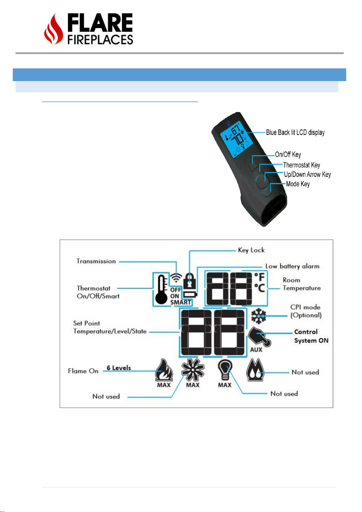
IFC PROFLAME 2 REMOTE BUTTONS:
- Main ON/OFF switch
- Main Burner Flame Modulation 6 Levels
- Choice of continuous or intermittent pilot mode
(intermittent is default mode)
- Thermostat or smart thermostat functions.
- Accent light modulation 6 levels (not used).
- Comfort fan speed modulation 6 levels (not
used).
10 | P a g e
REMOTE CONTROL SPECIFICATION:
- Need 4.5 voltage supply.
- 0-50 °C ambient temperature rating.
- 315 MHz radio frequency.
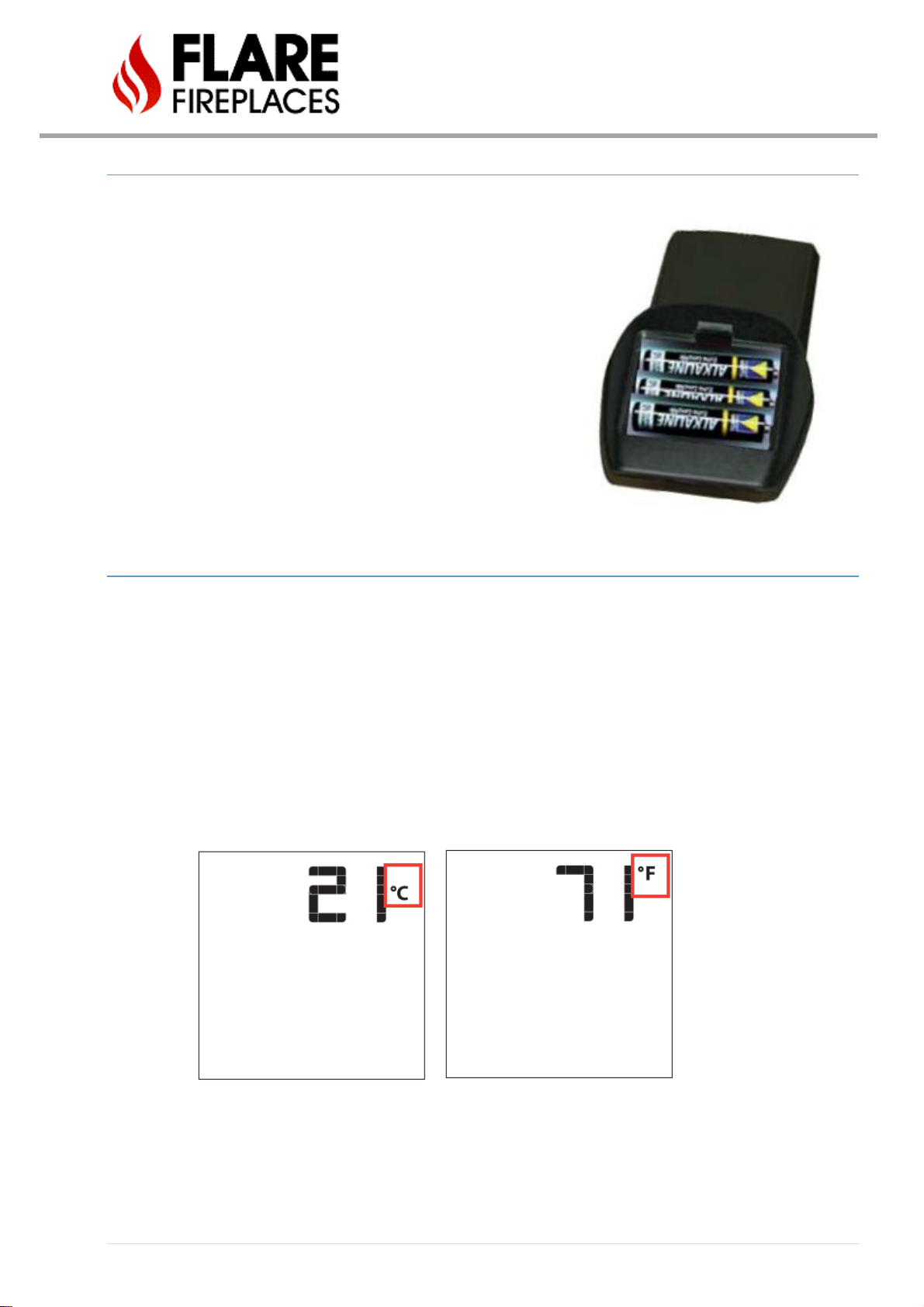
TEMPERATURE INDICATION DISPLAY
When the system is turned off the LCD screen will display the current room temperature in Fahrenheit (°F) or in Celsius
(°C.)
To change from Fahrenheit (°F) to Celsius (°C) or vice versa press the thermostat key and the mode key at the same
time.
11 | P a g e
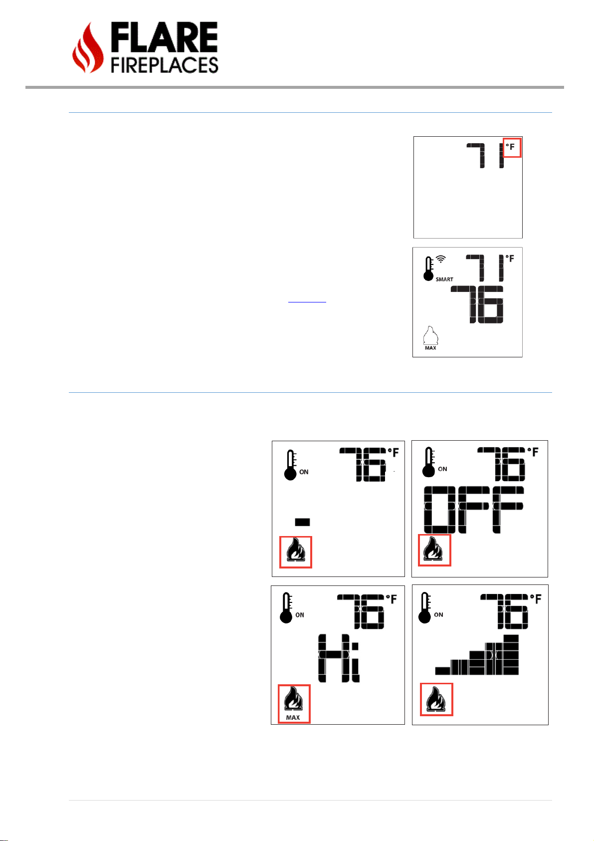
TURNING THE SYSTEM ON AND OFF USING THE REMOTE CONTROL
With the system OFF, press the ON/OFF Remote Key. The remote LCD will then
show other icons. At that time, the module will activate the appliance and a single
beep from the receiver will confirm reception command from the remote
When the system is ON, press the ON/OFF remote key, the remote LCD will show
the room temperature icon, at the same time the module will shut off the
appliance.
For information on using the remote and wall switch, click here.
REMOTE FLAME MODULATION
The Proflame 2 has 6 levels of modulation.
When the system is ON the flame level will be
at the maximum level.
By pressing the down arrow key once it will
reduce the flame height by one step.
Continued pressing of the down arrow will
result in the unit TURNING OFF. To return to
normal fireplace operation use the up-arrow
key to increase the flame height to HI.
If the up arrow has been pressed while the
system is ON, but the flame is OFF the flame
will come ON in the high position.
12 | P a g e
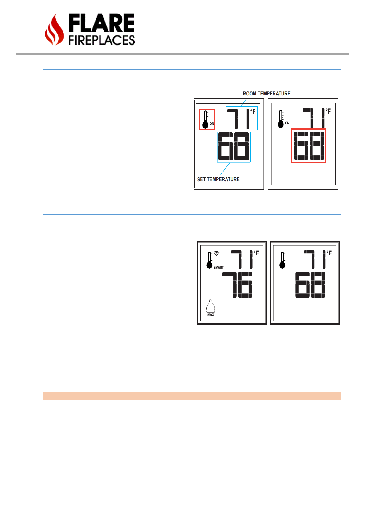
ROOM THERMOSTAT OPTION
The Remote control can operate as a room
thermostat. The thermostat can be set to a desired
temperature to control the room temperature. To
activate this option, press the thermostat key. The
thermostat icon on the LCD screen will display the
thermostat status is ON. The user can then set a suitable
temperature for the space. To adjust the desired
temperature, use the up or down arrow until the desired
temperature is displayed on the remote LCD screen.
SMART ROOM THERMOSTAT OPTION
The smart thermostat option will adjust the flame height
depending on the set temperature that has been set by the
user. When the room temperature gets close to the set
temperature the smart thermostat function will modulate
the flame down.
To activate the smart thermostat function, press the
thermostat key while the appliance is on until the word
SMART appears beside the icon of the thermostat.
To adjust the set temperature, press the up or down arrow
keys until the desired temperature is displayed on the LCD.
Note that: when the smart thermostat is activated, the flame level modulation is not activated.

13 | P a g e
FAN SPEED CONTROL
This feature is not used with the Flare fireplaces.
CONTINUOUS PILOT IGNITION/INTERMITTENT PILOT IGNITION (CPI/IPI)
By default, the Flare Fireplace is setup for IPI operation, but this can
be changed to CPI on screen units only. When the system is OFF
pressing the Mode key to index to CPI mode icon. Press the UP
arrow will select the CPI mode (but it is still not activated.) There is
also a switch on the CPI/IPI that is located on x5 port in the module.
Pressing down arrow key will activate the IPI mode at the same
time turn the IPI/CPI switch in X5 port on the module. A single beep
will confirm the command.
See page 85 for port location.
KEY LOCK
To avoid unsupervised operation of the remote control this feature has been
created. To activate this feature, press the mode and up arrow at the same time. A
lock icon will appear in the LCD screen. To deactivate this feature, press the mode
and up arrow at the same time.
LOW BATTERY POWER DETECTION
The life of the remote batteries depends on
- Battery quality
- Number of ignitions of the appliance
- The number of actions on the remote control
When the remote battery is low an empty battery icon will appear on the LCD Screen
CAUTION: DO NOT USE a screwdriver or other metallic object to remove the batteries from the battery box! This could
cause a short circuit to the system.
14 | P a g e
SIT BATTERY BACKUP -OPTIONAL – SCREEN UNIT ONLY
Batteries – Remote
• 3 x AAA (alkaline recommended).
• Low battery indicator on handsets with display.
• Battery replacement is recommended after 1 years.
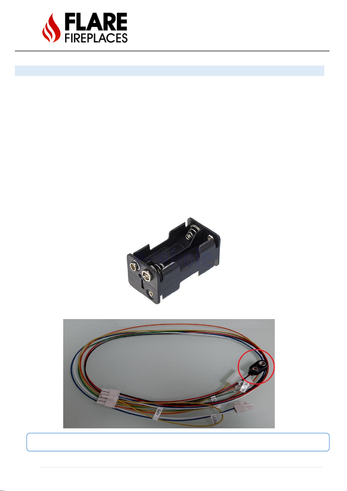
Batteries – Receiver
• 4 x 1.5 V “AA” (alkaline ONLY).
• An AC Mains Adapter may be connected in addition to batteries.
• Without using a mains AC adapter, battery replacement is recommended at the beginning of each heating
season as part of the yearly service check.
• Battery pack to be used with screen units only. Will not work on double glass units.
• Battery pack attaches to X5 cable at black end cap.
CAUTION: DO NOT attach “9V” battery to cable as it may damage unit. Only use the recommended “AA” batteries.
15 | P a g e
PAIRING REMOTE WITH FIREPLACE RECEIVER
Your remote will come paired with the fireplace receiver to allow for operation out of the box. In the event of a
remote or receiver replacement, use the following procedure to pair the remote with the receiver:
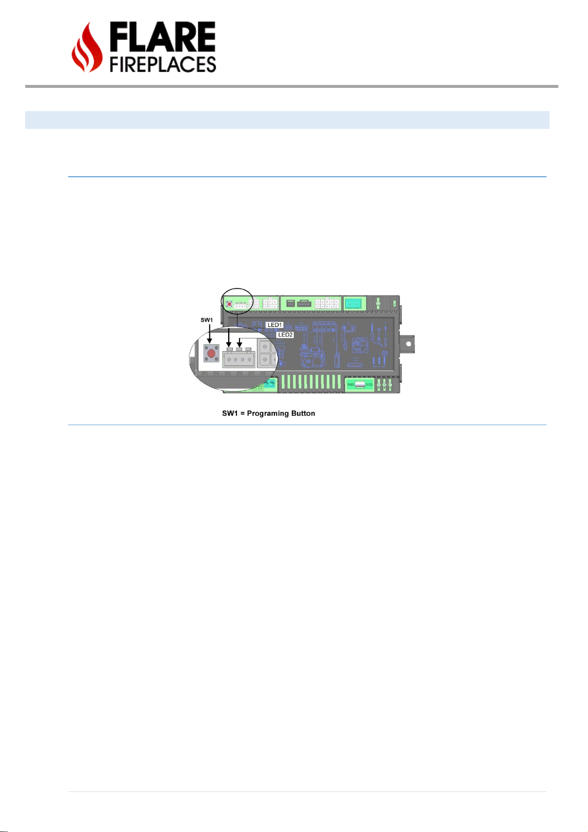
INITIALIZING THE SYSTEM FOR THE FIRST TIME
- Install 3 AAA type batteries in the remote battery bay located on the remote back.
- Press the SW1 button on the module see the following figure, the module will beep 3 times to indicate
that it is ready to synchronize with the remote.
- Press the ON/OFF button in the remote, the module will beep 4 times to indicate that the remote and the
module are synchronized to each other.
IGNITION SEQUENCE
Starting from OFF, press the remote power button. Four seconds after it is pushed the SIT module will send spark to
the pilot hood, and spark for 60 seconds. If there is no flame ignition during the first ignition sequence, the SIT module
will stop sparking for approximately 35 seconds and then begin sparking again. The second attempt will spark for 60
seconds. If there is no positive ignition after the second sequence the SIT module will go into a Lock Out and the LED
Indicator Light will blink three times in intervals until the system is reset.
- Ignition sequence will spark for 60 seconds, followed by a 35 second wait, 60 second spark and then lock out if flame
is not ignited.
- The lock out will blink on the LED indicator light will blink three times.
Reset Using the Transmitter ON/OFF power button: Turn the system off by pressing the remote power button. After
approximately 2 seconds press it again
Low Battery Condition (<4V) Remote Control: Battery icon will appear on LCD remote control display. Replace
batteries.
Low Battery Condition (<4V) Battery Backup: Red LED Indicator will blink (1) time in intervals. Low double-beep emitted from SIT control module when it receives an ON/OFF command from the remote control. Replace Batteries.
Pilot Flame Error Condition: Red LED Indicator will blink (2) times in intervals. Contact your dealer if this occurs.
System Lock Out Condition: Red LED Indicator will blink (3) times in intervals. Make sure gas is turned on and sensor is
not shorted. Follow Reset Using the Transmitter ON/OFF power button instructions above.
16 | P a g e
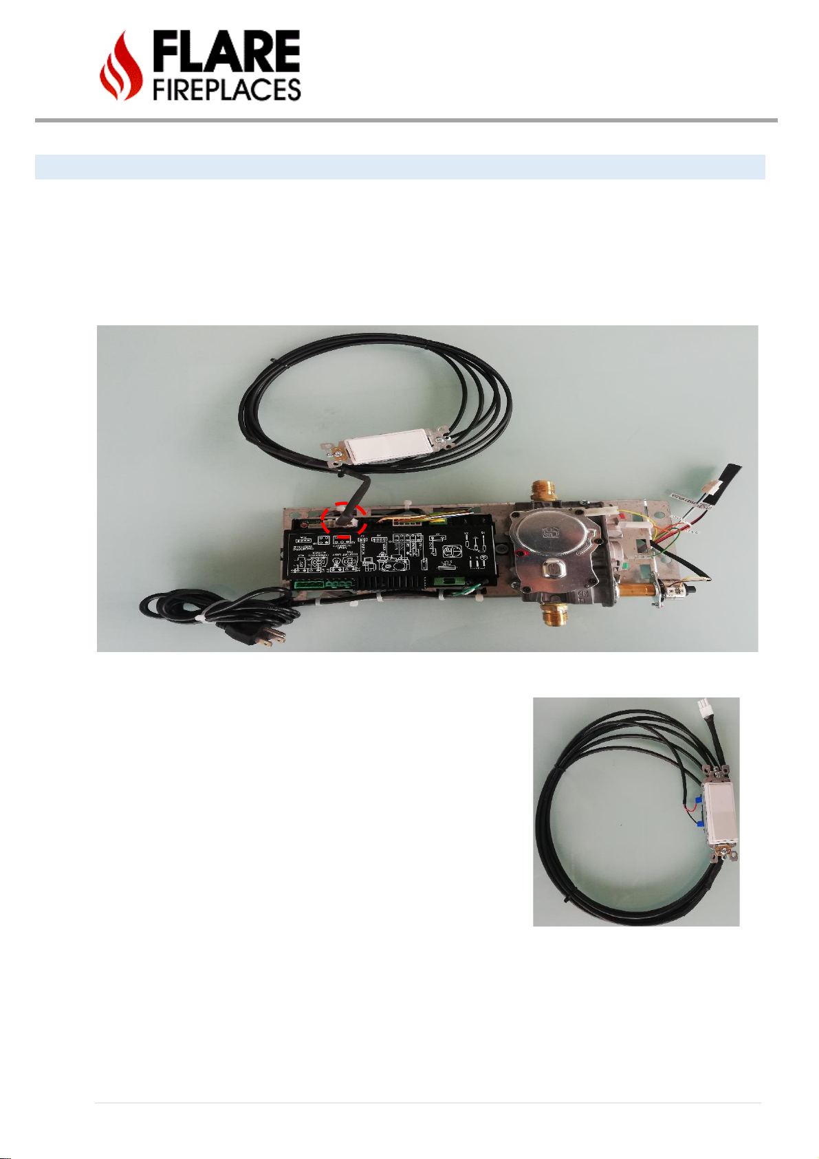
WALL SWITCH – OPTIONAL
In case of losing the remote control or empty batteries, there is another option to control the fireplace which is
located on the X8 port of the IFC module which the WALL SWITCH. The following operation can be done from the wall
switch:
- Turn ON fireplace
- Turn OFF fireplace
Note: Flare Fireplaces supplies each fireplace a wall
switch and a remote control to control the unit. Please
note, only one device should be used in a cycle of
powering the unit on and off. If you utilize the remote
control to power the appliance on, use the remote to
also power the unit off.
Trying to utilize different methods in a cycle could result
in one method failing to control unit until appliance has
been powered down and the cycle ended.
SIT wall switch can be run with up to 100 FT of wire.
17 | P a g e
MEDIA ARRANGEMENTS
Flare Fireplaces can be equipped with different media types. Follow the instructions below for information on how to
add and arrange media in your Fireplace:
• Do not place any type of media on the pilot or in front of the pilot. Keep 1” distance from the pilot to allow
correct operation of the pilot.
• Media can be put over the Flare burner. Avoid placing media over the main burner ports as it may disrupt
flame in case of a clogged port. Avoid placing driftwood arching over burner, instead place in front or behind.
• If using media that was not supplied by Flare Fireplace, make sure that the media is certified/suitable to be
used in direct vent gas fireplaces.
• Keep the pilot front cover view open to be able to view the pilot spark and flame from outside.
• Fireglass:
a. ¼” or ½” Fire Glass may be used.
b. When the fireplace viewing window is open, and media is placed, make sure Fire Glass does not fall
on the ceramic glass lower frame as that may cause breakage when putting back the ceramic glass.
c. Make sure pilot is clear of any Fire Glass particles.
d. Flare Fire Glass can be put safely into the firebox. Avoid overloading the burner with Fire Glass,
specifically over the main burner ports.
• Maintain minimum distance of ¼” from media to the fireplace glass panels.
• Use the manual for instructions on how to remove, replace, & arrange the fireplace glass media.
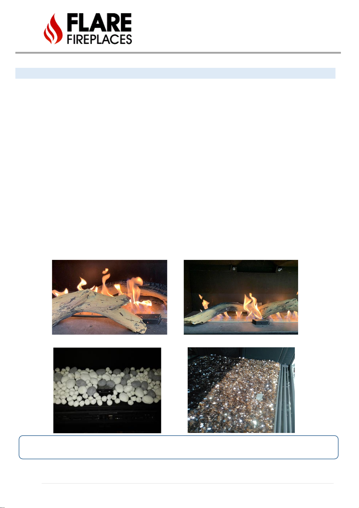
PROPER DRIFTWOOD PLACEMENT IMPROPER DRIFTWOOD PLACEMENT
Ceramic Pebbles Fireglass
CHOKING HAZARD! Ensure that the fireplace area is clear of fire glass particles as these could be ingested by small
children. Vacuum area after installation.
18 | P a g e
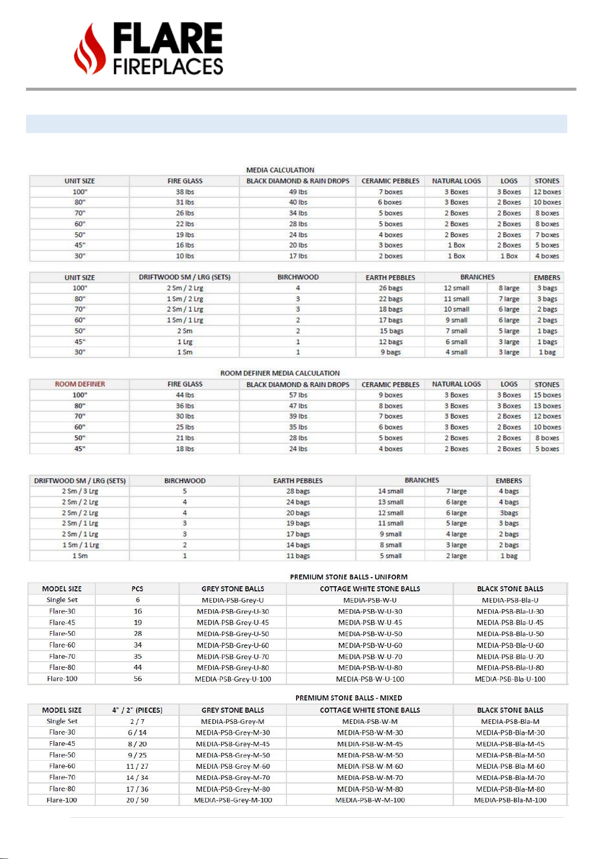
MEDIA CALCULATIONS
Please follow the below described quantities of media placement in your firebox. Please note, over saturation of
media throughout the firebox may result in improper combustion or Soot within the fireplace or termination cap.
19 | P a g e
FEATURE REMOVAL
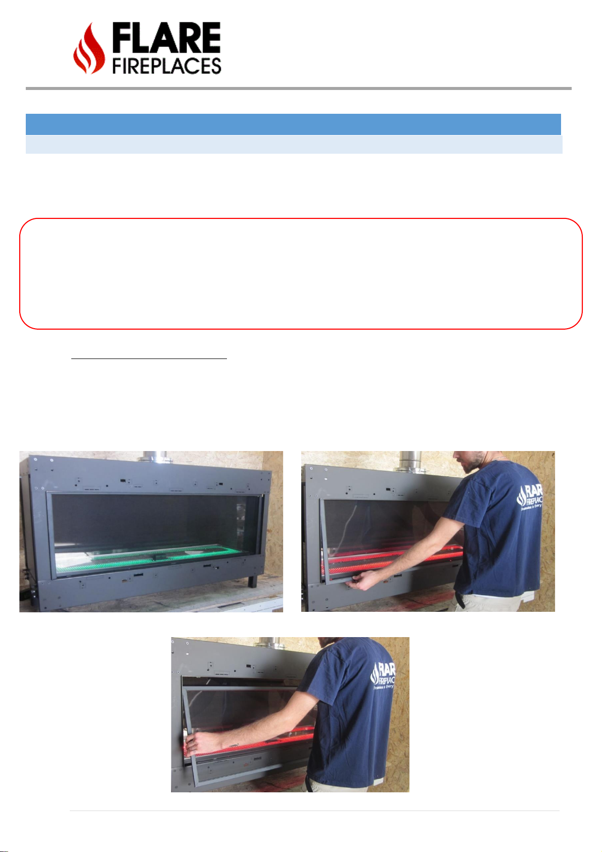
SAFETY SCREEN REMOVAL
Follow the instructions below for safety screen removal.
PLEASE NOTE: Safety screen may be shipped separately from the appliance.
The barrier is designed to reduce the risk of burns from the hot viewing glass and is
provided with this appliance. It must remain installed for the protection of children and
other at-risk individuals.
Do NOT operate the fireplace without the safety screen barrier.
Front, See Through, and Corner Units
• Safety screen removal requires no tools.
• Push the top frame of the screen up until it clears the bottom of the opening.
• Tilt the bottom of the screen out and pull down so the top frame clears the opening.
20 | P a g e
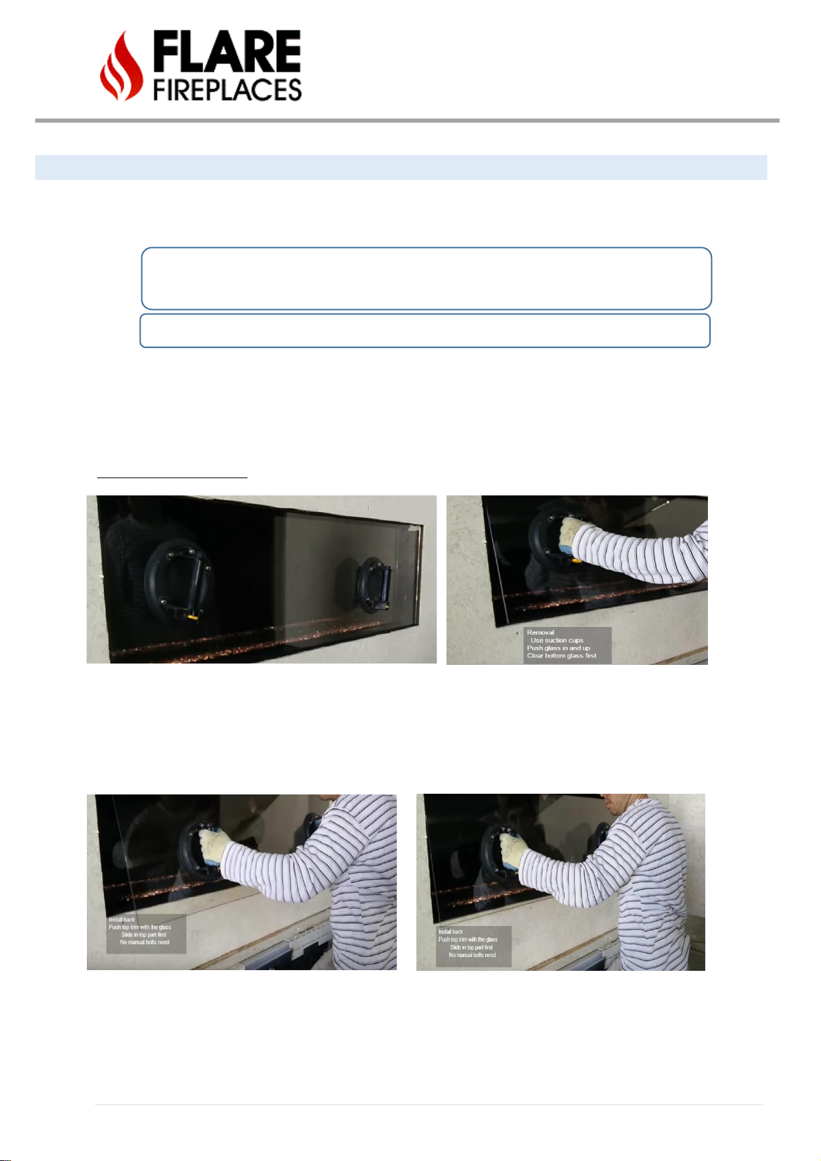
EXTERNAL TEMPERED GLASS REMOVAL – DOUBLE GLASS FIREPLACE
Follow the procedure below to remove and install back the fireplace external glass (double glass fireplace configuration).
Note: Suction cups are needed to remove the glass.
Warning! Turn off the fireplace and allow time for the unit to cool before proceeding.
Caution: The glass is very fragile and should be handled with care.
Warning! Double glass fireplace should NOT be operated without the external glass.
• Confirm lock screws have been removed during install (should be done once, during install only).
• Attach glass suction cups to the glass. Use more than one suction cup if needed (any unit above 45”).
• Using suction cups, slightly push in the external glass top edge.
• Once glass has been pushed, slightly lift the glass to clear bottom part of the glass.
• Remove the glass and place in a secure location.
Install back external glass.
• Attach glass suction cups to the glass. Use more than one suction cup if needed (any unit above 45”)
• Place upper edge of the glass in position and push latching trim.
• Once trim has been pushed in, slide glass top in position.
• Tilt in bottom edge of the glass in position as you are lifting the glass up.
• Glass is now secure in place. No bolts are needed to lock the glass.
21 | P a g e
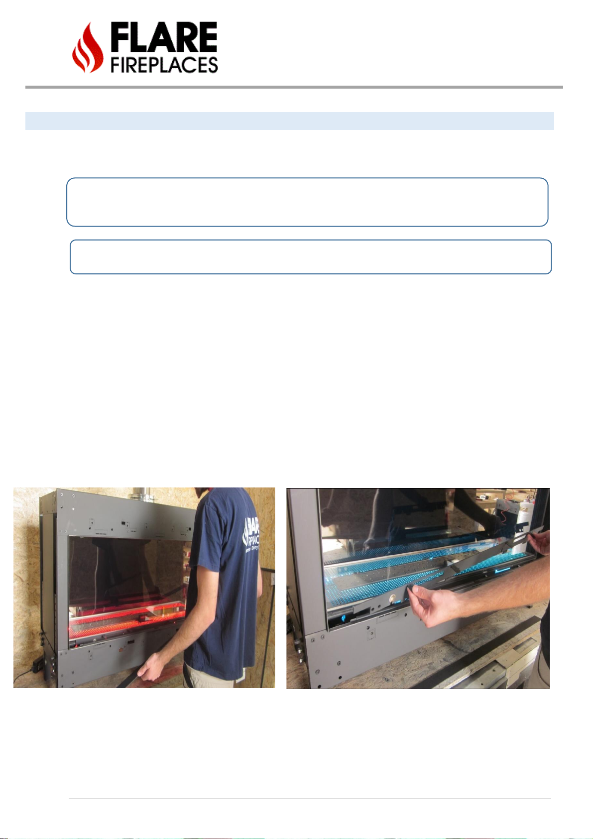
INTERNAL CERAMIC GLASS REMOVAL
Follow the procedures below to remove and install the internal ceramic glass (double glass fireplace configuration).
Note: Suction cups are needed to remove the glass.
Warning! Turn off the fireplace and allow time for the unit to cool before attempting to remove the glass.
CAUTION: The ceramic glass is very fragile and should be handled with care.
CAUTION: Do not operate the appliance with glass removed, cracked, or broken. Replacement of the panel(s) should
be done by a licensed or qualified service person.
Step 1 – Attach glass suction cups to the glass. Remove the glass’ lower magnetic trim. Place the trim in a secure
place. Any unit above 45” requires 2 suction cups to hold the glass.
Step 2 – Release the lower glass trim. The lower trim bolts can be released by hand and should not require any tools.
Once bolts are released remove lower glass holder trim.
Step 3 – Hold the glass suction cups and hand release trim bolt on the top. The trim does not need to be removed and
will only open to allow a gap for glass removal.
Step 4 – Push the glass up and clear it from the bottom as shown.
When putting the glass back, DO NOT overtighten the bolts or glass may break.
Step 1 Step 2
22 | P a g e
Step 3 Step 4-1
Step 4-2
When putting back the glass, DO NOT overtighten the bolts or glass may break.
• Use step 4 – 1 for putting the glass back.
• Glass trim screws should be closed hand tight. DO NOT overtighten the bolts or glass may break.
23 | P a g e
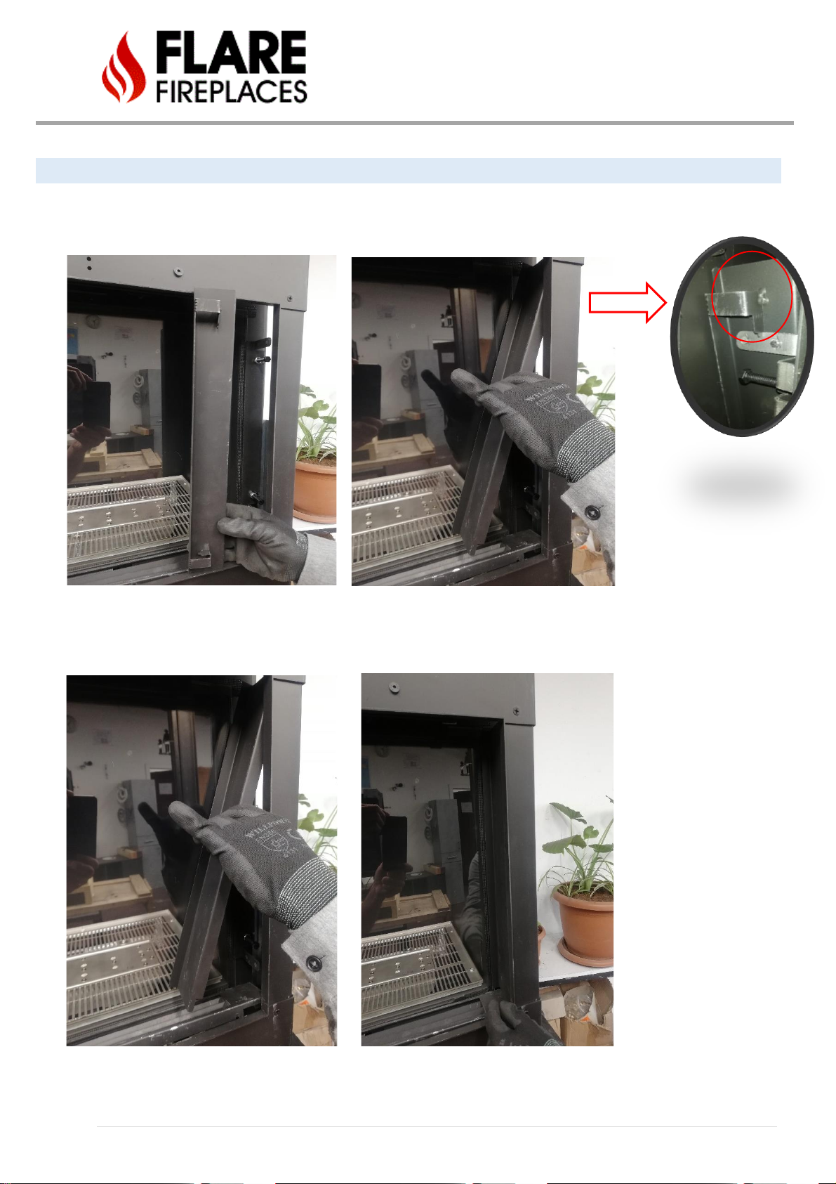
SIDE GLASS TRIM REMOVAL / INSTALLATION – FLARE H & EH
Side Glass trim for Front & ST unit (R, H, EH) is installed by Hanging the side trim over the trim holder as shown in the picture
below.
Then moving the lower side of the trim toward the holder as shown in the picture below.
24 | P a g e
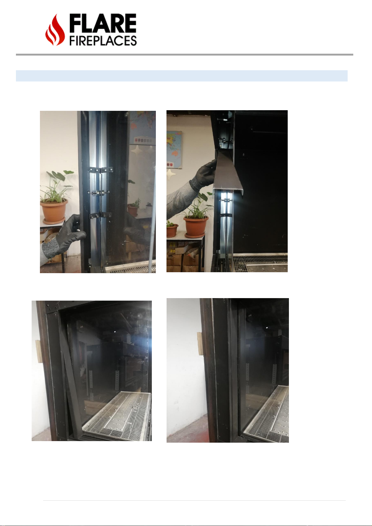
SIDE GLASS TRIM REMOVAL / INSTALLATION (C & RD)
Side Glass trim for C & RD unit (R, H, EH) is installed by placing the side trim over the trim holder magnetics as shown in the
picture below.
Then moving the lower side of the trim toward the holder as shown in the picture below.

25 | P a g e
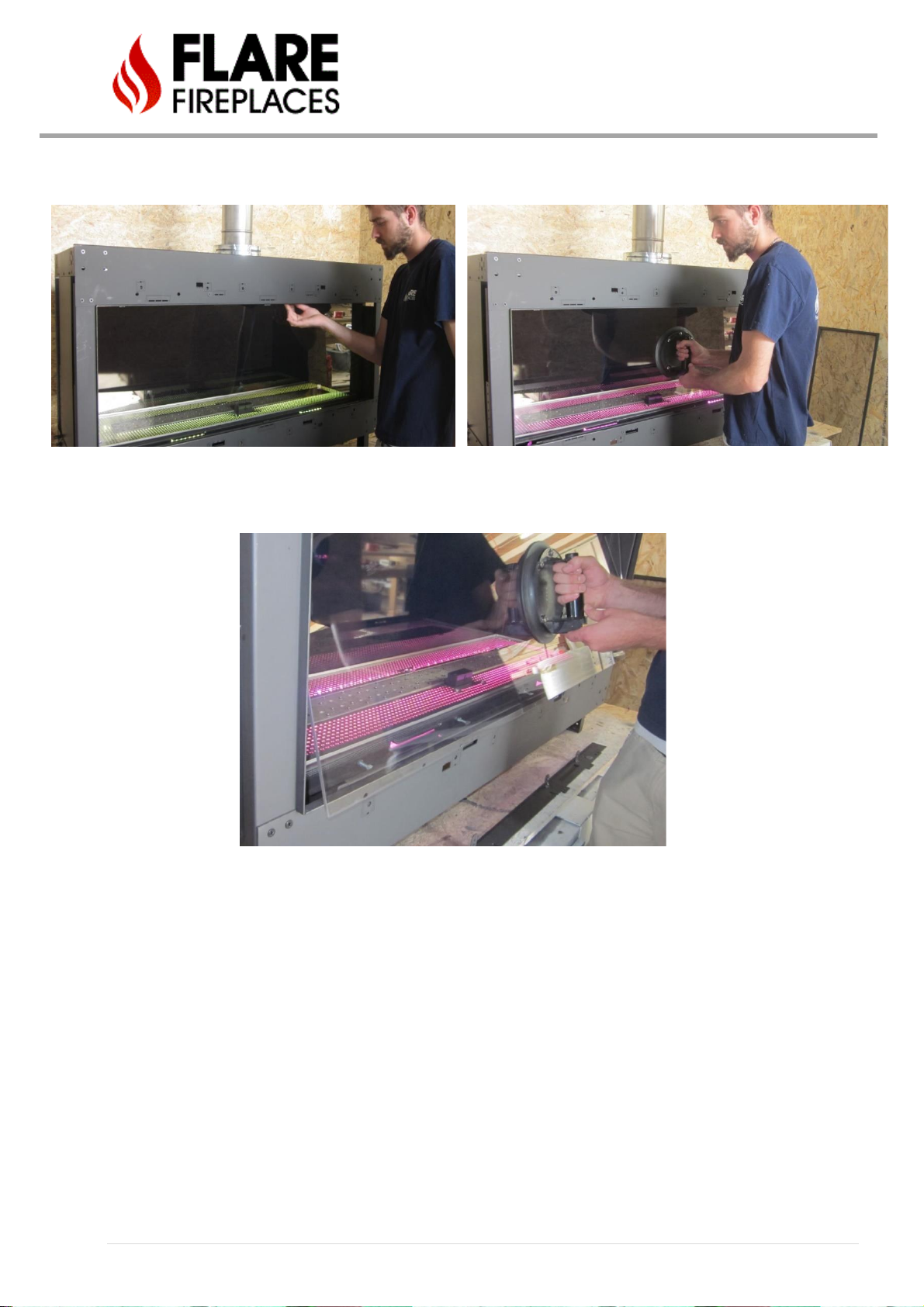
REFLECTIVE BACK INSTALL
The Flare Fireplace may be ordered with a reflective ceramic glass backing. The ceramic glass is tinted black to create
a reflection when the fireplace is running. The ceramic glass will enhance and protect the fireplace look and is easy to
clean.
The reflective back is shipped outside the unit, inside a sleeve with the other glass panes. It should be mounted at the
back of the fireplace, placed in the gap between the fire bed (shown yellow below) and held by the top mounting
brackets (red circle).
Carefully carry the reflective back using suction cups, and place at a 45-degree angle as shown below.
Screw the mirror clamp as shown below, make sure you do not over-tighten the screw, & leave 1” of the screw
length out.
26 | P a g e
INSTALLATION STEPS
1. Prior to starting the installation, make sure you read and understand all WARNING information in the
manual. Do not start the installation if you are unclear about any of the installation related subjects.
2. Determine the following:
• The vent system configuration to be used based on the fireplace location. Follow the manual venting
section (Chimney path installation & planning tables) to determine the venting requirements and
setting.
Note: Venting requirements are model specific.
Note: Make sure the vent requirements are supported by the Flare manual and installation
instruction.
• Clearance requirements from combustible and non-combustible materials. Follow the clearance
instruction and example in the manual.
Note: Clearance instructions and examples are model specific.
• Gas supply piping.
• Confirm if the fireplace is going to operate using Natural Gas (NG) or Propane. Use the attached
product label to confirm the fireplace is set for the expected gas type.
• Electrical wiring requirements.
• Framing and finishing details.
3. Unpack the fireplace box, adjust telescopic legs and place in the upright position. Follow instruction for
fireplace unpacking.
4. Put the Fireplace in the desired location. Verify clearance to non-combustible and combustible materials.
Follow the clearance instruction and example in the manual.
5. For LED units, connect LED system and test LED.
6. Attach the units back bracket to the wall framing.
7. For double glass units only: remove glass locking screws and discard.
8. Adjust Fireplace vent restrictor based on vent configuration and planning guide. Document vent restrictor
setup here: ___________________________.
9. Connect vent system to the Fireplace.
10. Connect gas (Gas connection section) line to the Fireplace and verify gas inlet and outlet pressure. Measure
and document gas pressure here: Inlet _______ W.C.
11. Confirm if adjustments for high altitude are needed (Installation at above 2000 Ft from sea level).
12. Connect electrical wiring for applicable units.
13. Insert and place Fireplace media. Use media arrangement guide from the manual.
14. Verification of:
• Ignition and pilot system.
• Burning and flame.
15. Complete framing and wall cover.
Read all the instructions before starting the installation. Follow these instructions carefully during the installation to ensure
maximum safety and benefit.
Follow the Steps above to insure proper installation of the Gas appliance.
WARNING! Risk of Fire or Explosion! Damaged parts could impair safe operation. DO NOT install damaged, incomplete or
substitute components.

27 | P a g e
INSTALLATION PREPARATION
ACCESS PANEL
Flare recommends you build an access panel somewhere near the fireplace. This will provide easy access to all the
necessary parts that may need servicing, over time. While Flare also offers access to these components by going inside
the fireplace, with instructions HERE, you will find having a dedicated area where all your components can be easily
accessed for servicing, without the need to remove the glass, media, & burner is the preferred method.
HIDDEN ACCESS PANEL EXAMPLE

28 | P a g e
FIREPLACE UNPACKING
Follow the instructions below for unpacking the unit:
• Check the packing and confirm there is no external damage. If damage exists, please notify Flare Fireplaces
immediately.
• Remove the top wood studs and pull the external carton box up.
• Please do not remove the blue wrap completely at this stage.
• Leave the fireplace placed on the pallet for the next step: Fireplace legs setup.
29 | P a g e
FIREPLACE TELESCOPIC LEGS SETUP
The fireplace legs will need to be set up once box is removed. The legs can be configured so that the bottom of the
glass will be between 10”-19” above the floor. This means the bottom of the fireplace will be 4”-13” above the floor.
Follow the steps below for telescopic legs setup prior to final positioning of the fireplace.
On Corner units (Flare-RC/LC/DC/RD) front legs will need to be assembled.
Fireplace must NOT be installed without telescopic legs extracted to a minimum of 3”.
Installing fireplace without telescopic legs is a fire hazard.
Installing the Fireplace without legs (sitting on the fireplace frame) may bend the frame & cause glass breakage.
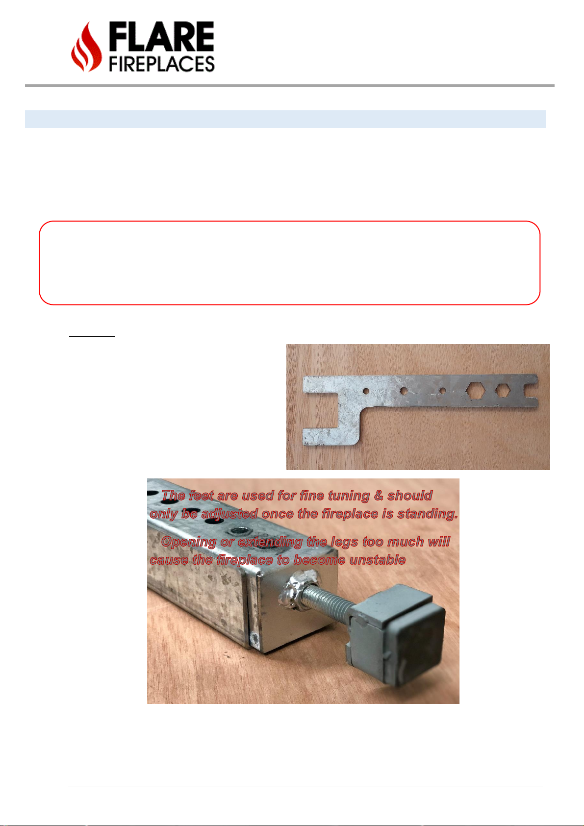
Fine Tuning
After extending the legs to the desired length, use
the wrench included to fine tune the feet so that
the fireplace is level.
Note that the feet are intended for minimal
adjustments and not to be extended completely for
extra height. Doing so will make the fireplace
unstable.

30 | P a g e
LEG SETUP FOR FRONT AND SEE-THROUGH UNITS
• Step1 - Release the pin.
• Step2 – Release the 2 screws from the leg.
• Step 3 – Extend the telescopic leg to the desired length, minimum 4” (That will set the fireplace 10” from the
bottom of the glass to the floor).
• Step 4 – Retighten the three screws to secure the telescopic leg in position. Note that the top pin inserts into
the holes only for alignment. The two bottom screws tighten down on the legs.
• Step 5 – Repeat Steps 1-4 for each on the fireplace so that they are all extended to the same length.
• Step 6 – Stand the fireplace up and fine tune the feet with the wrench included so the fireplace is level. Open
the screws to raise the fireplace. Close the screws to lower the fireplace.
Step 1 Step 2
Step 3 Step 4

31 | P a g e
LEG SETUP FOR CORNER UNITS
Included are 4 screws, 2 adjustable legs, 1 foot for fine tuning, and 1 special wrench for adjusting the feet while the
fireplace is standing.
• First, identify the correct order to connect the legs. The first adjustable leg that attaches to the fireplace has
Rivnuts as seen in the image below. The second adjustable leg has a place for the foot to be screwed in on
the bottom as seen in the images below.
• Next, determine which holes to insert the 4 screws so that the fireplace will stand at the desired height after
the foot for fine tuning is also screwed in.
• Insert the 4 screws into the holes and Rivnuts beneath and tighten. Screw in the foot so that it can later be
adjusted to slightly raise or lower the fireplace.
• Configure remaining legs to the same height.
• Stand the fireplace up and fine tune the feet with the wrench provided so the fireplace is level. Open the
screws to raise the fireplace. Close the screws to lower the fireplace.
The levelers are used for
fine tuning & should only be
adjusted once the fireplace is
standing.
Opening or extending the
legs too much will cause the
fireplace to become unstable

32 | P a g e
UNPACKING CONTROL UNIT AND ACCESSORIES
Unpack the accessories (remote, power adapter & wall switch). The gas valve, receiver, control module (for double
glass units) will remain wrapped until first test of unit.
• Place accessories (white bag) in a secure location.
• The control unit (gas valve and receiver) is attached to the fireplace on an “umbilical cord”. Once fireplace is
moved to its final location the control unit can be put close to the service access door.
Gas valve and receiver:
***GAS VALVE WILL COME WRAPPED, ONLY TO BE OPENED FOR UNITS FIRST FIREUP
Optional control module for double glass units.
33 | P a g e
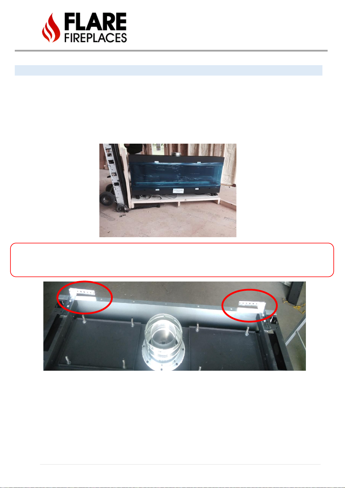
FIREPLACE POSITIONING
Once Fireplace has been set to the upright position, it can be moved to its final installation location.
• Make sure the control unit is secure and not dragging on the floor during transport and positioning.
• Unit should remain on the pallet during transport inside the site location.
• When positioning the fireplace, take into consideration the clearance requirements and framing. Use the
manual clearance guide for more details.
• Attach the fireplace top brackets to the metal stud in the back to secure the fireplace in place. The bracket
length can be adjusted by releasing the screws on the top.
Fireplace should remain on the wood pallet when carried to final installation location.
Do not attempt to use a pallet jack or any other moving tools if the unit has been removed from the wood pallet as it may harm
the fireplace components under the unit.
Make sure to use only non-combustible material in case top the brackets need to be extended to connect to the
back or sides.
34 | P a g e
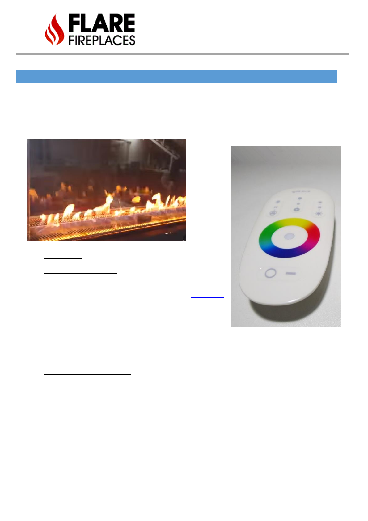
LED LIGHTS
The Flare Fireplace can be ordered with optional multi-color interior RGB LED lighting. The lights allow perfect flames to be
viewed across a bed of illuminated crushed glass, or any other direct vent approved media option.
RGB LED – The multicolored option is controlled by a remote for the color selection. Once the color has been selected by the
operator, the LED memory will remember that color for the next time the unit is turned on.
LED Operation:
Option 1 – Double Glass unit
• LED power is connected to the Flare control system (Labeled in
picture above as LED Power Outlet, and below as Connection C)
• LED will turn On and Off with the fireplace, controlled by the
fireplace remote or wall switch.
• Color control can be done by the LED remote.
• Once a color is selected, the LED remote can be stored away.
• LED to be switched Off when fireplace is turned off.
• LED cannot be switched on when fireplace is off.
Option 2 – Screen or Double Glass
• LED can be connected to independent power source, home automation system or smart outlet.
• LED can be turned ON/OFF from LED remote, independent from the fireplace.
• LED can be turned on, even when fireplace is off.

35 | P a g e
LED LIGHT INSTALL AND POWER
It is best if LED lights are connected and tested during the initial stages of installation to allow easy access under the
unit (before the wall finishing material is done).
Testing the LED light requires a 110V power source.
Installation steps:
1. Remove all LED components from the shipping bag.
2. Components are pre-connected prior to shipping. Connect LED connectors (points A) to the fireplace using
the quick connect connectors.
3. Connect LED control system to the power supply (point B)
4. Connect LED Power supply to an external power source (point C). Do not connect the LED to the Flare control
LED plug at this point. Use the LED remote to turn the LED on the LED system.
Once testing is done, connect the LED power adapter to final power source (Point C), Option 1 or Option 2 as
detailed in the previous page.
Power outlet on the Flare control is optional for LED ONLY

36 | P a g e
LED CONTROLLER AND REMOTE
Product Specification
The Flare high-performance RGB LED touch remote controller adopts the most advanced PWM control technology. This remote
controls all RGB LED products with 4 lines of circuits (COMMON ANODE), owning 64 thousand colors & 20 automatic changing
modes to choose from. RBG Strip is using 24V DC power adapter.
REMOTE
MATERIAL
110x52x20mm
POWER
AAA Battery *2pcs
MATERIAL
ABS
FABRICATION PROCESSING
Multicolor Printing & UV
Varnish
CONTROLLER
SIZE
85x45x23mm
WORKING VOLTAGE
DC12V~24V
CONTROL WAY
RGB 3 CHANNELS
MAX LOAD PER CHANNEL
6A
OUTPUT CONNECTION
COMMON ANODE
TELECONTROL DISTANCE
30 METERS
PROGRAMS
20 KINDS
LED
Strip
LED
POWER

37 | P a g e
Mode selection and remote
NUMBER
MODE
BRIGHTNESS
STATE
SPEED STATE
1
STATIC WHITE
ADJUSTABLE
UNADJUSTABLE
2
WHITE COLOR GRADUAL CHANGES
ADJUSTABLE
ADJUSTABLE
3
ALL COLORS GRADUAL CHANGES
ADJUSTABLE
ADJUSTABLE
4
RED/GREEN/BLUE 3 COLORS GRADUAL
CHANGE
ADJUSTABLE
ADJUSTABLE
5
7 COLORS JUMP TO CHANGE
ADJUSTABLE
ADJUSTABLE
6
3 COLORS JUMP TO CHANGE
ADJUSTABLE
ADJUSTABLE
7
RED/GREEN JUMPS TO CHANGE
ADJUSTABLE
ADJUSTABLE
8
REB/BLUE JUMPS TO CHANGE
ADJUSTABLE
ADJUSTABLE
9
BLUE/GREEN JUMPS TO CHANGE
ADJUSTABLE
ADJUSTABLE
10
WHITE COLOR FREQUENTLY BLINKS
ADJUSTABLE
ADJUSTABLE
11
WHITE COLOR GLITTERS
ADJUSTABLE
ADJUSTABLE
12
RED COLOR FREQUENTLY BLINKS
ADJUSTABLE
ADJUSTABLE
13
RED COLOR GLITTERS
ADJUSTABLE
ADJUSTABLE
14
GREEN COLOR FREQUENTLY BLINKS
ADJUSTABLE
ADJUSTABLE
15
GREEN COLOR GLITTERS
ADJUSTABLE
ADJUSTABLE
16
BLUE COLOR FREQUENTLY BLINKS
ADJUSTABLE
ADJUSTABLE
17
BLUE COLOR GLITTERS
ADJUSTABLE
ADJUSTABLE
18
YELLOW COLOR FREQUENTLY BLINKS
ADJUSTABLE
ADJUSTABLE
19
YELLOW COLOR GLITTERS
ADJUSTABLE
ADJUSTABLE
20
CIRCULATION MODE
Code Matching:
Please follow the instructions below:
- Confirm it is correctly connected between power supply, LED controller & LED load.
- Switch the power off, then switch it on again, & press key 5 once (within 3 seconds) the moment you see
the light is on.
- The LED will blink twice slowly when it is completed.
Code Clearing:
The code can be cleared as needed. The kit (remote & controller) will stay in the original state after code clearing and
can work again when code re-matching is done.
Please follow the instructions below:
Confirm it is correctly connected between power supply, LED controller & LED load.
- Switch the power off, then switch it on again, & long press key 5 (within 3 seconds) the moment you see
the light is on.
- The LED blinks 9 times swiftly when completed.
38 | P a g e
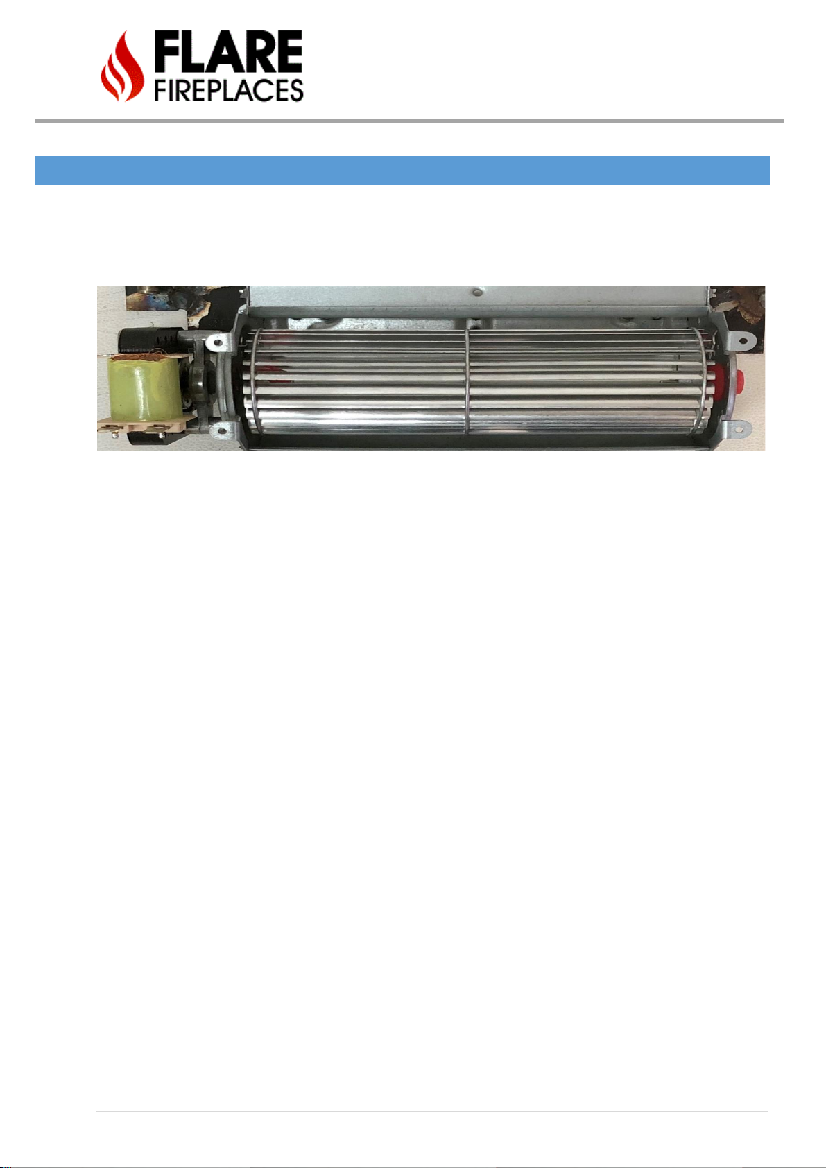
OPTIONAL BLOWER KIT FOR SCREENED UNIT
The Flare silent blower kit ships standard on all Double Glass units, keeping the glass cooler to the touch,
but can also be added to a safety screened unit to circulate more heat from the front of the fireplace into
the room.
On a Flare screen unit, the blowers will be installed and delivered with an 110V Plug. The operation of
the blowers is controlled with a power ON/Off to the outlet they are connected to.
The customer has the option to:
• Install a smart outlet to control the blowers.
• Use a wall switch to start & shutdown the blowers whenever they want. An electrician will need
to wire the wall switch to control the power to the fireplace fans.
• Buy a remote system for the outlet.
Please note that the blowers will need air intake to work. (Same requirements for double glass) For
reference to the air intake specifications for your unit please see pg. 74 of Flare Install Manual.

39 | P a g e
VENT TERMINATION
Framing for vents in combustible walls and ceilings:
When passing through combustible walls and ceilings, framing will depend on the type of vent installation -- horizontal
or vertical. Ensure that the insulation is kept clear of the vent pipe using either a wall thimble or an attic insulation
shield. Follow the installation instructions supplied with the individual venting components.
These instructions should be used as a guideline and do not supersede local codes in any way. Install venting according to local
codes, these instructions, the current National Fuel Gas Code (ANSI-Z223.1) in the USA or the current standards of CAN/CSA-
B149.1 in Canada.
Approved Pipe - This appliance is approved for use with M&G DuraVent venting and ICC.
DO NOT mix pipe, fittings or joining methods from different manufacturers.
For detailed DuraVent chimney installation information please use the M&G DuraVent direct vent installation manual:
http://www.duravent.com
For detailed ICC chimney installation information please use the ICC direct vent installation manual:
http://icc-chimney.com/en/exceldirect
Instructions
• Where a vent pipe passes through a floor or ceiling, a ceiling firestop MUST be used to retain insulation and
maintain proper clearances. Use roof support brackets where needed.
• Install the first section of vent pipe into the collar on top of the fireplace.
• Connections between each vent system component must be tightly joined and secured. Follow the vent
manufacturer’s instructions for information on how to seal and secure vent and vent connections.
• Horizontal runs of vent pipe must be supported to prevent any downward sags. Horizontal pipe sections should
be supported at least every 4 feet. Wall Straps can be used for this purpose.
• When installing the vent pipe, make sure that the vent pipe is supported by the structural/frame surrounding and
not by fireplace.
Follow the vent manufacturer’s instruction for information on how to install, seal, and secure vent and vent
connections.
DO NOT pack insulation around the vent. Insulation must be kept back from the pipe to prevent overheating.
ALWAYS maintain specified clearances around venting and firestop systems. Install wall shield and ceiling firestops as specified.
WARNING!

40 | P a g e
VENT AND FIREPLACE SIZE
*Flare-RD-45 is shipped with 5x8 vent. All other Flare 45 are shipped with the 4x6 vent.
MINIMUM COMBUSTIBLE CLEARANCES FROM VENT
• HORIZONTAL VENT CLEARANCES: A minimum clearance of 3 inches (76mm) to the top and 1 inch (51mm) to the sides and
bottom of the vent pipe on all horizontal runs to combustibles is required.
• VERTICAL VENT CLEARANCES: A minimum of 1 inch (25mm) all around the vent pipe on all vertical runs to combustibles is
required except for clearances in appliance enclosures.
• Horizontal vents have a minimum 1/4 inch (6mm) rise per 1 foot towards the termination.
• When penetrating through combustible walls and ceilings, frame a minimum of 10.5 in x 10.5 in opening and ensure that
the insulation is kept clear of the vent pipe using either a wall thimble or an attic insulation shield. use the DuraVent
framing cutout dimension table based on your selected part.
Frame cutout table taken from the DuraVent or ICC installation manual.
Size
Vent Size
Flare 30
4x6
Flare 45*
5x8 or 4x6 *
Flare 50
5x8
Flare 60
5x8
Flare 70
5x8
Flare 80
5x8
Flare 100
5x8

41 | P a g e
VERTICAL TERMINATION
See the table on the previous page for minimum cutout dimensions or frame openings around wall venting.
Make sure clearances to combustible material are maintained based on vent part used. Note: size of vents
depends upon specific fireplace and cutout sizes vary according to the DuraVent or ICC part number used.
Minimum height from roof to lowest discharge opening.
Vertical Vent Termination Opening/Framing will
depend on the part used. See table above or vent
installation manual.
• Minimum 24” horizontal clearance to any surface (such as an exterior wall) for vertical terminations
42 | P a g e
Multiple terminations
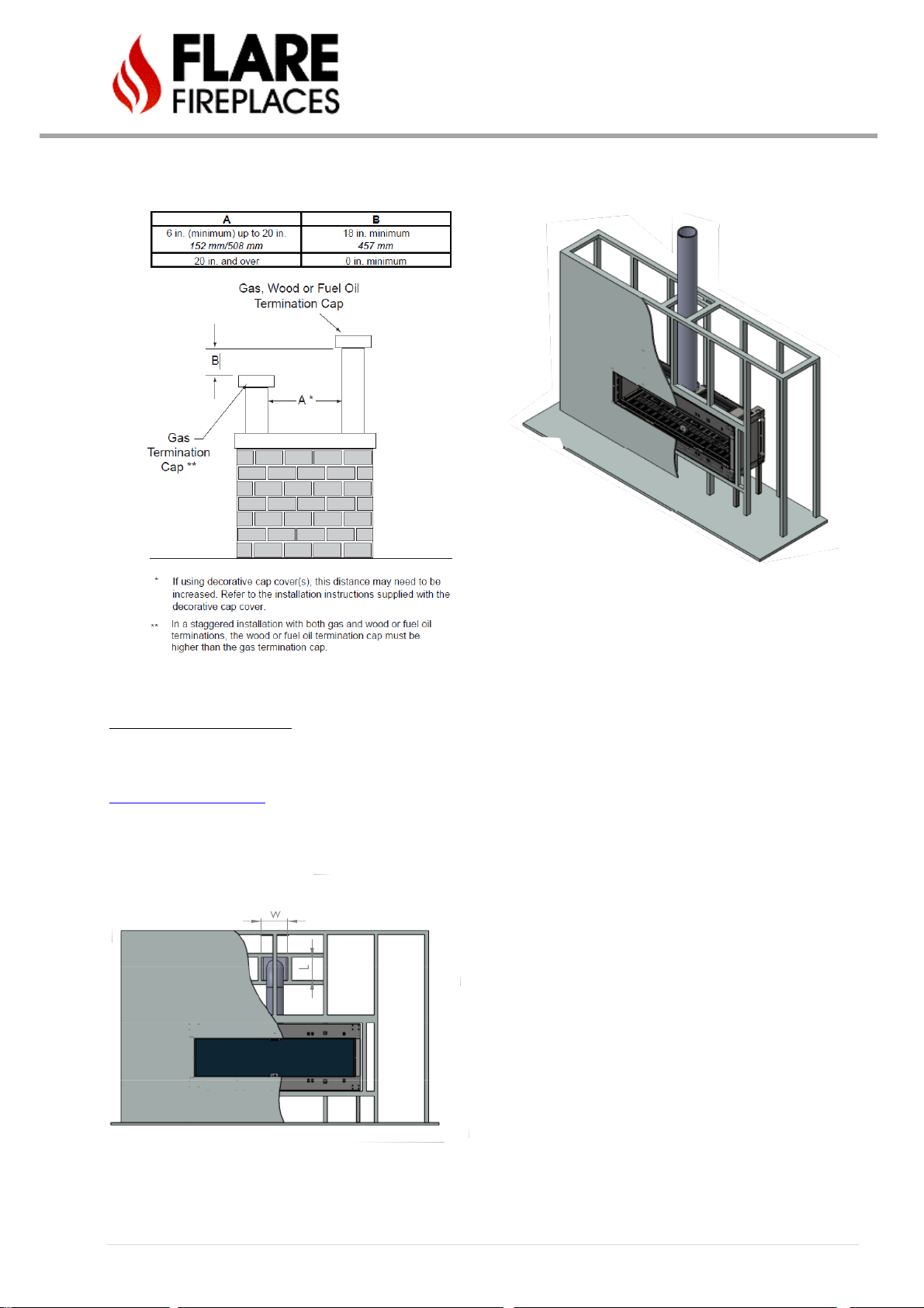
HORIZONTAL TERMINATION
A minimum distance of 18 inches should be kept between multiple horizontal terminations.
See the table on page 32 for minimum cutout dimensions or frame openings around wall venting. Make sure
clearances to combustible material are maintained based on vent part used. Note: size of vents depends upon specific
fireplace and cutout sizes vary per the DuraVent part number used.

43 | P a g e
VENT TERMINATION CLEARANCES
A
*12” (30 cm) min.
Clearances above grade, veranda, porch, deck, or balcony
B
*12” (30 cm) min.
Clearance to window or door that may be opened
C
12” (30 cm) min.
Clearance to permanently closed window recommended to prevent
condensation on window
D
**24” (61 cm) min. for Flare units 100”
**18” (46 cm) min. for Flare units 80” and below
(vinyl surfaces require 24” (61 cm) min.)
Vertical clearance to ventilated soffit located above the terminal within a
horizontal distance of 2 feet (60 cm) from the edge of the terminal
E
30” (76 cm) min. for Flare units 80” and 100”
18” (46 cm) min. for Flare units 70” and below
(vinyl surfaces require 24 inches (61 cm) min.)
Clearance to unventilated soffit.
F
6” (15 cm) min.
Clearance to outside corner
G
6” (15 cm) min.
Clearance to inside corner
H
3’ (90 cm) min.
*Not to be installed above a meter/regulator assembly within 3 feet (90 cm)
horizontally from the centerline of the regulator
I
3 feet (90 cm) min.
Clearance to service regulator vent outlet
J
*12 inches (30 cm) min.
Clearance to non-mechanical air supply inlet to building or the combustion air
inlet to any other appliance
K
*6 feet (1.8 m) min.
Clearance to a mechanical air supply inlet
L
*7 feet (2.1 m) min.
^ Clearance above paved sidewalk or a paved driveway located on public
property
M
**24” inches (76 cm) min. for Flare units 100”
**18” inches (46 cm) min. for Flare units 80” and
below (vinyl surfaces require 24 inches (61 cm)
min.)
Clearance under veranda, porch, deck, or balcony

44 | P a g e
^ a vent shall not terminate directly above a sidewalk or paved driveway which is located between two single family
dwellings and serves both dwellings
** only permitted if veranda, porch, deck, or balcony is fully open on a minimum of 2 sides beneath the door*
• Clearance in accordance with local installation codes and the requirements of the gas supplier.
* As specified in CGA B149 Installation Codes, note local Codes or Regulation may require different clearances.
* For U.S.A. Installations follow the current National Fuel Gas Code, ANSI Z223.1
***Horizontal vent termination minimum clearance to adjacent structure or fence is 48”.
**** Minimum 24” horizontal clearance to any surface (such as an exterior wall) for vertical terminations
45 | P a g e
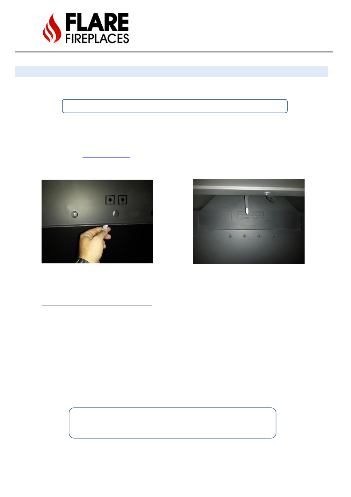
VENT RESTRICTOR SETUP
Flare Fireplace direct vent system is equipped with a vent restrictor. Use Chimney Path Installation and Planning on
the next page to determine the right vent restrictor setup for your installation.
Vent restrictor changes and setup should only be done by a certified installer.
• The unit leaves the factory with the vent restrictor open.
• The vent restrictor is adjusted using a 10mm wrench below the front upper frame.
• The vent restrictor setting is from 1 (minimum restriction) to 6 (maximum restriction).
• The installer will document the restrictor setting in the end of the installation.
• Use the vent planning guide and table to determine the restrictor setting.
Signs the vent restrictor needs to be adjusted:
Vent restrictor should be opened if the flame has the following characteristics:
• Flame is excessively tall and lifting.
• Flame lacks movement.
Vent restrictor should be closed if the flame has the following characteristics:
• Flame height is low.
• Flame has excessive movement
Document any change to the restrictor setting.
Contact Flare Fireplaces for support if needed.

46 | P a g e
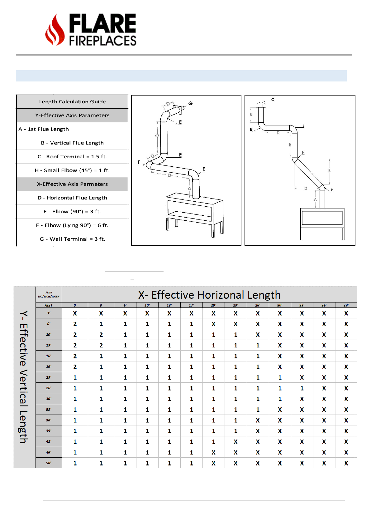
CHIMNEY PATH INSTALLATION AND P LANNING
Before vent installation, the installer should read these instructions to ensure the proper vent configuration has been selected.
To calculate the vent runs, use the following tables and instructions. Please note that power vent runs are model (burner)
specific. Use the tables below to calculate the restrictor setting. These fireplaces are designed and tested to function with natural
venting in equal pressure environments. The natural venting allows hot air and CO2 to rise and exhaust out through the vent
naturally while simultaneously creating a slight draft of oxygen to allow the flame to burn clean and efficiently. Please know that
if your installation environment presents negative or positive pressure, caused by strong HVAC systems or kitchen hoods, a
power vent system may be needed to counter this unique environment.
General Instructions
• Diagonal runs have both vertical and horizontal vent aspects when calculating the effects. Use the rise for the
vertical aspect and the run for the horizontal aspect.
• Various combinations of vent runs may be used. Refer to the tables below based on Fireplace size. Use the attached
example for clarification on how to use the table.
• The numbers in the table represent the restrictor setting based on the vent path.
• Symbol “x” in the table means the path is not allowed.
• Setting the restrictor to 1 means there is no restriction.
• Numbers in the table represent the restrictor setting to be set.
• Document the restrictor setting configuration prior to leaving the installation site.
• The tables apply to both NG (Natural Gas) and Propane.
• Minimum 3 ft vertical run (A) required before any bend or turn.
o See Flare Front and Flare See Through exception.
o See Flare 50 & 60 5x8 table for exception
• A maximum of four 90º vent elbows are allowed in the vent run. Any configuration with more than 4 elbows
requires vent review and approval from Flare Fireplaces.
• Two 45º elbows may be used in place of one 90º elbow.
• The tables represent the manufacturer’s guideline based on testing and design. Additional external factors may
affect the restrictor choice needed. If flame appears to be not typical, please contact Flare Fireplaces for restrictor
size recommendations.
• Use the empty table in the page below to document and calculate the installation vent path.
• Any venting pathway that does not appear the tables below require approval from Flare Fireplaces.
For optimum performance and flame appearance, keep the vent length to a minimum and limit the number of elbows.
47 | P a g e
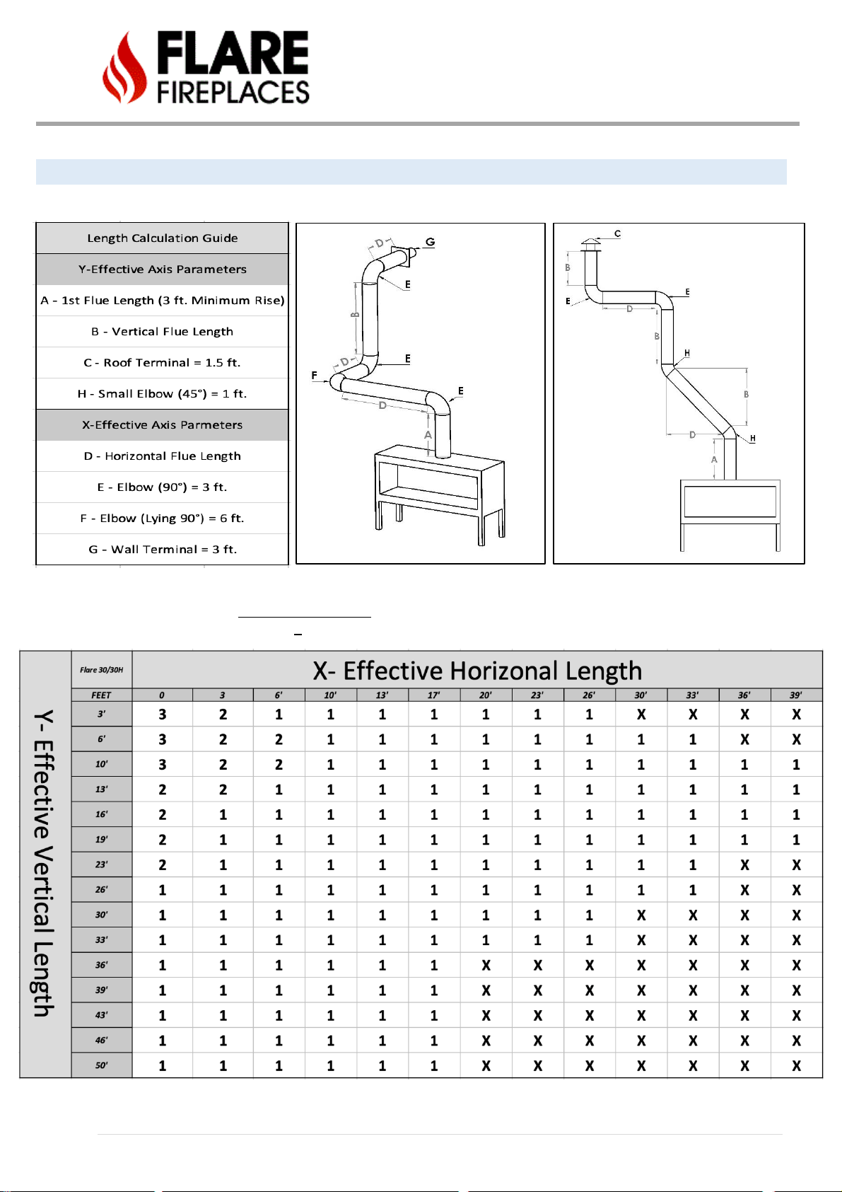
FLARE 30/30H
Suitable for all Flare 30 Fireplaces
Vent Restrictor Setting: Set to 1-6 based on Table below.
X: Run may need to be Power Vented

48 | P a g e
FLARE 45/45H/45EH
Suitable for all Flare 45/45H/45EH Fireplaces
Vent Restrictor Setting: Set to 1-6 based on Table below.
X: Run may need to be Power Vented

49 | P a g e
FLARE 50/50H/50EH
Suitable for all Flare 50/50H/50EH Fireplaces
Vent Restrictor Setting: Set to 1-6 based on Table below.
X: Run may need to be Power Vented

50 | P a g e
FLARE 60/60H/60EH
Suitable for all Flare 60/60H/60EH Fireplaces
Vent Restrictor Setting: Set to 1-6 based on Table below.
X: Run will need to be Power Vented
51 | P a g e
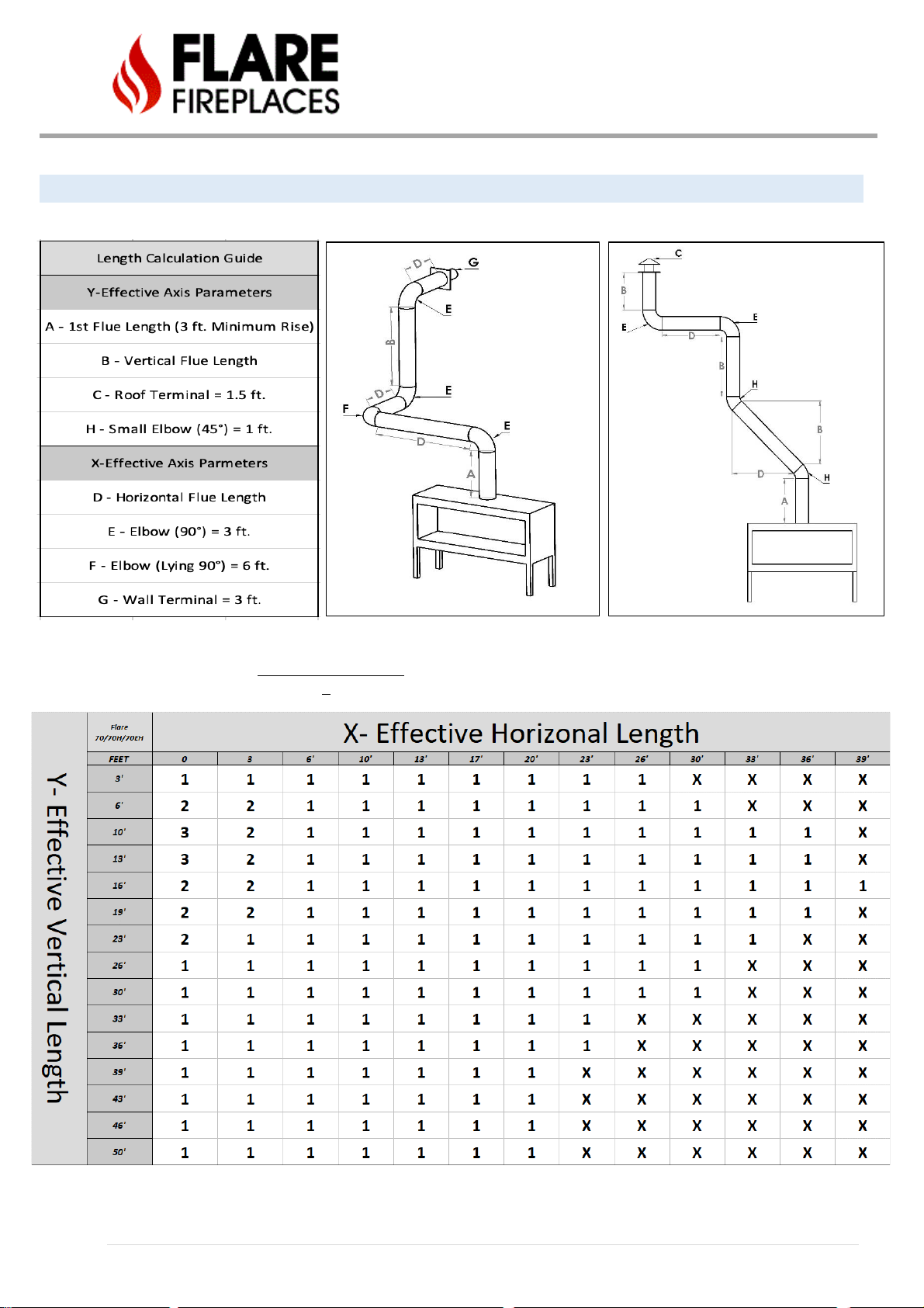
FLARE 70/70H/70EH
Suitable for all Flare 70/70H/70EH Fireplaces
Vent Restrictor Setting: Set to 1-6 based on Table below.
X: Run will need to be Power Vented

52 | P a g e
FLARE 80/80H/80EH
Suitable for all Flare 80/80H/80EH Fireplaces
Vent Restrictor Setting: Set to 1-6 based on Table below.
X: Run will need to be Power Vented
(6ft. Minimum Rise)
53 | P a g e
FLARE 100/100H/100EH
Suitable for all Flare 100/100H/100EH Fireplaces
Vent Restrictor Setting: Set to 1-6 based on Table below.
X: Run will need to be Power Vented
(6ft. Minimum Rise)

54 | P a g e
POWER VENTING
For unsupported vent routes (based on the gravity vent tables above) a power venting solution is required. The power venting
solutions allow Flare Fireplaces to operate in vent conditions that would not be possible without the motor unit. See the Flare
Power Vent Installation Manual for more specific instructions.
The system is designed and tested with DuraVent 3x5 gasket direct vent pipes. It is critical for the safety and operation of the
system to use the DuraVent 3x5 gasket system.

55 | P a g e
When using the power vent system, direction of flow through the vents can be up, down, horizontal or diagonal since the system
is sealed and vacuumed. The vent restrictor level should be set based on length in feet, number of elbows and the vent
termination.
NOTE: A minimum of 20 feet of venting is required between the fireplace and the in-line power vent. Do not use the power vent
if the vent routing is less than 20 feet. Refer to the Flare Power Vent Installation Manual for more specific instructions.
Clearance - Clearances between the vent pipe and combustible materials must be maintained at 3” inches top and 1” for side
and below. Maintain the same clearance from the power vent box to any combustible materials.
Power vent unit must be installed by a qualified installer in accordance with these instructions.
CAUTION! Failure to install, operate, and maintain the power venting system in accordance with manufacturer's instructions
will result in conditions which may produce bodily injury and/or property damage

56 | P a g e
ELECTRICAL CONNECTION TO THE PV SYSTEM
• The PV system will be getting 115V from the Flare Fireplace board.
• The PV system is connected to the Fireplace control system with a High voltage 4 wire cable - labeled below as
connection “PV Power 115V”.
• Cable to be used is 16 AWG-4 copper wire . Cable is not included with the PV kit and can be sourced spertly.
• Connect 4 wire high voltage cable from the Power Vent to matching colors - white to white, black to black & green to
green and red to red on the PV system.
• The Flare Fireplaces Fan board is a must for operating a Flare Fireplace with a PV system.
57 | P a g e
GAS INSTALLATION
GENERAL
WARNING! Risk of Fire or Explosion!
All gas handling and installation should be performed by qualified service technician or installer.
Gas build-up during line purge could ignite. Ensure adequate ventilation. Make sure there are no
ignition sources/sparks or open flames.
Do not change the gas valve setting! The fireplace gas valve has been preset at the factory.
Installing an external manual gas valve before connection to the fireplace is a must.
Make sure to check for gas leaks before lighting the fireplace for the first time. When checking for
leaks do not use open flame.
This appliance and its individual shut off valve must be disconnected from gas supply piping system during any pressure testing
of that system at test pressures more than ½ psig (3.5 kPa).
This appliance must be isolated from the gas supply piping system by closing its individual manual shut off valve during any
pressure testing of the gas supply piping system at test pressures equal to or less than 1/2 psig (3.5 kPa).
• Move the appliance into position and secure it to the wall using the back or side mount.
• Install a manual gas valve before the connection to the fireplace appliance automatic valve.
• Connect the gas line to the fireplace. The appliance is designed to accept a 1/2” (13mm) gas supply.
• Connect the gas supply in accordance with local codes, CAN/CSA-B149.1 in Canada or to the current National Fuel Gas
Code, ANSI Z223.1 / NFPA 54 in the United States.
• Check for gas leaks using non-corrosive commercially available leak-check solution before operating the gas appliance.
• Measure and document gas pressure here: Inlet _______ W.C. Burner (Manifold) _______ W.C. -- Make sure the
Min/Max inlet pressure match the table below.
• Lighting the fireplace for the first time may take some time until the line is purged.
Note: Do not place the gas valve or controls above the level of the burner.
Gas Pressure
Natural Gas
Propane
Inlet pressure
7.0" W.C
10". W.C
Acceptable Inlet Gas pressure table
WARNING! Risk of Fire or Explosion! High pressure will damage valve. Low pressure could cause explosion.
Verify inlet pressures. Verify minimum pressures when other household gas appliances are operating.

58 | P a g e
Have the gas supply line installed in accordance with local codes, if any. If not available, follow ANSI 223.1.
Installation should be done by a qualified installer approved and/or licensed as required by the locality (in the Commonwealth
of Massachusetts installation must be performed by a licensed plumber or gas fitter).

59 | P a g e
USING A REDUCER TO DE-RATE YOUR FLARE FIREPLACE
Flare Fireplaces appliances use the SIT ProFlame II valve and are tested/approved for installations at elevations of 0–4500 feet (0–
1372 meters) above sea level using the standard burner orifice sizes. At the time of installation, it must be determined by the
installer if the appliance needs to be de-rated for elevations above 4500 feet. Contact your local gas supplier for the de-ration
requirements in your area. Only use the Flare Fireplaces de-rating reducer on installations above 4500 Ft. If the installer must
convert the unit to adjust for varying altitudes, the information sticker must be filled out by the installer and
adhered to the appliance at the time of conversion.
DE-RATE TABLE
MODEL
GAS TYPE
REDUCER SIZE
CALC BTU.
STANDARD BTU
30”
LPG
1.6 mm
18000
23000
45”
LPG
1.9 mm
22000
28000
50”
LPG
2.0 mm
27000
35000
60”
LPG
2.2 mm
36000
43000
70”
LPG
2.5 mm
38000
45000
80”
LPG
2.7 mm
42000
49000
100”
LPG
2.9 mm
51000
57000
30”
NG
3.0 mm
27000
33000
45”
NG
3.2 mm
30000
36000
50”
NG
3.5 mm
35000
45000
60”
NG
3.8 mm
40000
51000
70”
NG
4.1 mm
44000
52000
80”
NG
4.5 mm
48000
55000
100”
NG
4.7 mm
49000
57000
60 | P a g e
ADDING THE FLARE FIREPLACES DE-RATING REDUCER
Add the de-rating reducer when your fireplace is being installed at elevations over 4500 ft above sea level.
Please contact your local gas supplier for de-ration requirements in your area.
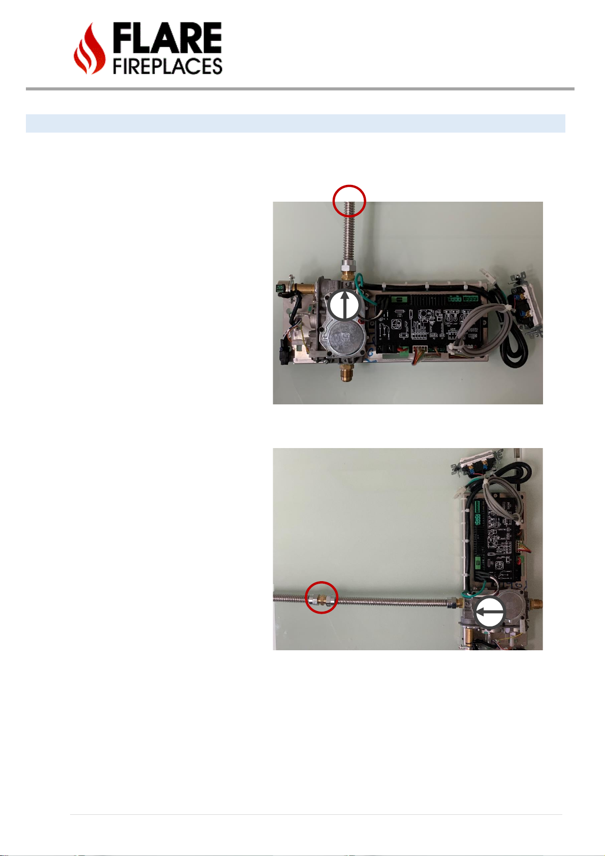
1. Shut off gas, remove power, and locate
your gas valve. Once disconnected, verify
direction of gas flow by locating the flowarrow on top of the valve. Turn off gas and
remove hard line to valve.
SEE EXAMPLE 1
2. Add reducer between gas hard line and
flex line connected to SIT ProFlame valve
on the burner side. Us appropriate reducer
as specified in “DE-RATE TABLE”.
SEE EXAMPLE 2
EXAMPLE 2
BURNER SIDE
EXAMPLE 1
BURNER SIDE
61 | P a g e
ORIFICE SIZE
Flare Fireplace appliances are tested and approved for installations at elevations of 0–4500 feet (0–1372 meters) above sea
level using the standard burner orifice sizes. At the time of installation, it must be determined if the appliance needs to be derated. Contact your local gas supplier for deration requirements for your area. De-rated installation consideration can start at
2000 Ft above sea level. At higher elevations, the amount of BTU fuel value delivered must be reduced by either using gas that
has been de-rated by the gas company or by changing the burner orifice to a smaller size as regulated by the local authorities
having jurisdiction and by the (USA) National Fuel Gas Code NFPA 54/ANSI Z223.1 - latest edition or in Canada, the CAN/CSAB149.1 code – latest edition.
GAS VALVE ACCESS DOOR
The Flare Fireplace gas valve and control system is on an “umbilical cord” that can be stretched up to 50” from the middle of
the fireplace and be put next to the access door location. Do not place the gas valve or controls above the level of the burner.
If the fireplace is to sit low on the floor, the controls must be placed outside the non-combustible zone or insulated from the
heat from the fireplace. The access door can be placed on any side of the fireplace, below the non-combustible line. The use of
a 10”x10” access door is highly recommended. If no access door is installed, it is possible to access the gas valve from inside
the fireplace by removing the glass. The access door can also be used as a lower air intake for a double glass installation if it is
perforated, and the opening requirements are maintained. The access door can be concealed in many ways such as HVAC vent
cover, removable tile connected with Velcro straps and more.
MANUAL GAS SHUT OFF
The installation of this appliance REQUIRES the implementation of a readily accessible Manual Gas Shut Off. Confirm
requirements of location and shut off type with your local codes. NOTE: The Electronic Ignition of Flare Fireplaces DOES NOT
satisfy the requirement for a Manual Gas Shut Off. See below for example of Manual Gas Shut Off

62 | P a g e
LIQUID PROPANE USAGE IN A FLARE FIREPLACE
The Flare Fireplace can operate and fire using Natural Gas (Default) or Liquid Propane gas. If your installation requires the
fireplace to operate using Liquid Propane gas, make sure only to use the Flare Fireplaces liquid propane conversion kit.
Depending on your fireplace ignition system, LPG conversion kit may include the following:
• LPG burner orifices
• Pilot LPG orifices
• SIT Valve LPG Conversion Kit
NEVER OPERATE A FIREPLACE ORDERED FOR NATURAL GAS WITH LP GAS UNLESS CONVERTED BY A
CERTIFIED FIREPLACE TECHNICIAN. USE ONLY FLARE FIREPLACE LP CONVERSION KIT. ALWAYS MEASURE
GAS INLET PRESSURE AND OUTLET PRESSURE POST CONVERSION
Your Fireplace may be shipped to support Liquid Propane Gas. Check your Flare Fireplaces gas rating plate at the back of your valve
to confirm the gas type.
Use the following link for the Flare Fireplace NG to LPG conversion on SIT ignition
Use the following link for the Flare Fireplace NG to LP conversion on Maxitrol ignition
NOTICE
Flare Fireplaces does offer the ability to run your fireplace with a liquid propane tank though there are certain
limitations this fuel type presents when compared to the usage of natural gas. Liquid propane burns more
efficiently and hotter than natural gas so to accommodate this increase in heat we must use smaller orifices to achieve a
lower BTU that can cause your flame to appear smaller than on a unit run on natural gas. Flame height on Flare Fireplaces using
Liquid Propane is roughly 4-6” in height because of this adjustment.

63 | P a g e
COMMONWEALTH OF MASSACHUSETTS
State of Massachusetts Carbon Monoxide
Detector/Vent Terminal Signage Requirements for all side wall horizontally vented gas fueled equipment installed in every dwelling, building or structure used
in whole or in part for residential purposes, including those owned or operated by the Commonwealth and where the side wall exhaust vent termination is less
than seven (7) feet above finished grade around the venting, including but not limited to decks and porches, the following requirements shall be satisfied:
1. INSTALLATION OF CARBON MONOXIDE DETECTORS. At the time of installation of the side wall horizontal vented gas fueled equipment, the installing
plumber or gas fitter shall observe that a hard-wired carbon monoxide detector with an alarm and battery back-up is installed on the floor level where
the gas equipment is to be installed. In addition, the installing plumber or gas fitter shall observe that a battery operated or hard-wired carbon
monoxide detector with an alarm is installed on each additional level of the dwelling, building or structure served by the side wall horizontal vented
gas fueled equipment. It shall be the responsibility of the property owner to secure the services of qualified licensed professionals for the installation
of hard-wired carbon monoxide detectors.
a. If the side wall horizontally vented gas fueled equipment is installed in a crawl space or an attic, the hard-wired carbon monoxide detector with
alarm and battery back-up may be installed on the next adjacent floor level.
b. If the requirements of this subdivision cannot be met at the time of completion of installation, the owner shall have a period of thirty (30) days to
comply with the above requirements; provided, however, that during said thirty (30) day period, a battery-operated carbon monoxide detector
with an alarm shall be installed.
2. APPROVED CARBON MONOXIDE DETECTORS. Each carbon monoxide detector as required in accordance with the above provisions shall comply with
NFPA 720 and be ANSI/UL 2034 listed as IAS certified.
3. SIGNAGE. A metal or plastic identification cation plate shall be permanently mounted to the exterior of the building at a minimum height of eight (8)
feet above grade directly in line with the exhaust vent terminal for the horizontally vented gas fueled heating appliance or equipment. The sign shall
read, in print size no less than one-half (1/2) inch in size, “GAS VENT DIRECTLY BELOW. KEEP CLEAR OF ALL OBSTRUCTIONS”.
4. INSPECTION. The state or local gas inspector of the side wall horizontally vented gas fueled equipment shall not approve the installation unless, upon
inspection, the inspector observes carbon monoxide detectors and signage installed in accordance with the provisions of 248 CMR 5.089(2)(a) 1
through 4.
(b) EXEMPTIONS. The following equipment is exempt from 248 CMR 5.089(2)(a) 1 through 4.
1. The equipment listed in Chapter 10 entitled “Equipment Not Required to Be Vented” in the most current edition of NFPA 54 as adopted by the Board; and
2. Product Approved side wall horizontal vented gas fueled equipment installed in a room or structure separate from the dwelling, building or structure used
in whole or in part for residential purposes.
(c) MANUFACTURER REQUIREMENTS – GAS EQUIPMENT VENTING SYSTEM PROVIDED. When the manufacturer of Product Approved side wall
horizontally vented gas equipment provides a venting system design or venting system components with the equipment, the instructions provided by
the manufacturer for installation of the equipment and the venting system shall include:
1. Detailed instructions for the installation of the venting system design or the venting system components; and
2. A complete parts list for the venting system design or venting system.
(d) MANUFACTURER REQUIREMENTS – GAS EQUIPMENT VENTING SYSTEM NOT PROVIDED. When the manufacturer of a Product Approved side wall
horizontally vented gas fueled equipment does not provide the parts for venting the fuel gases, but identifies “special venting systems”, the following
requirements shall be satisfied by the manufacturer.
1. The referenced “special venting system” instructions shall be included with the appliance or equipment installation instructions; and
2. The “special venting systems” shall be Product Approved by the Board, and the instructions for that system shall include a parts list and detailed
installation instructions.
(e)) A copy of all installation instructions for all Product Approved side wall horizontally vented gas fueled equipment, all venting instructions, all parts
list for venting instructions, and/or all venting design instructions shall remain with the appliance or equipment at the completion of the installation.

64 | P a g e
FLARE FIREPLACES - DOUBLE GLASS
OVERVIEW
With an effort to make our fireplaces safer, Flare Fireplaces is offering our full line of products with safety double glass
technology. The Flare Fireplace double glass is built with two layers of glass. The design allows cool air to flow between the two
layers, with the help of built-in blowers, which significantly lowers the temperature of the external glass, making it safe for a brief
touch. Double Glass is suitable for commercial as well as residential use.
The double glass feature provides a sleek look with no frame, while maintaining heating characteristics and efficiency. This
feature does not affect the clearance or venting requirements.
65 | P a g e
DOUBLE GLASS - INSTRUCTIONS
The double glass design depends on the blower’s ability to move room temperature air from the lower air intake, up between the
internal and external glass, through the chase above the fireplace, and out the upper heat release. These relatively quiet blowers
cannot be turned off and are required for the continued operation of your Double Glass system.
Top Hot Release - The release/ outlet for hot airflow from the wall enclosure MUST remain OPEN. The outlet must be at the top
part of the enclosure but not necessarily at the front, so long as the measurements below are maintained. Heat release opening
can be installed at the sides of the enclosure (one on every side), back or on top of (in case of a drop wall design).
For fireplaces sized 80” & 100”– vent area must be at least 200 square inches OPEN AIR FLOW.
For fireplaces sized 60” & 70” - vent area must be at least 140 square inches OPEN AIR FLOW.
For fireplace sized 50” and below - vent area must be at least 100 square inches OPEN AIR FLOW.
Lower Air Intake - Optional for normal safety screen installation. Required for installation with double glass or safety screen
with optional blower kit.
For fireplaces sized 80” & 100” – vent area must be at least 100 square inches OPEN AIR FLOW.
For fireplaces sized 60” & 70” - vent area must be at least 70 square inches OPEN AIR FLOW.
For fireplaces sized 50” and below - vent area must be at least 50 square inches OPEN AIR FLOW.
FOR SEE THROUGH FIREPLACES THE AIR INTAKE REQUIREMENTS ARE DOUBLE, EQUAL ON BOTH SIDES.
NOTE: Openings above for Heat Release and Air Intake are measured for open air space. The fans for the Double Glass cannot
be turned off during operation.
To reduce your chase and double glass heat increase your heat release & air intake above listed minimum.
The upper heat release may be a single or multiple opening if the total size of all the openings is at least the minimum
requirement listed above. They can be set at the front, back, sides or top.
The lower air intake may be a single or multiple opening if the total size of all the openings is at least the minimum requirement
listed above. They can be set at the front, back, or sides. It is recommended to place one long opening on below the long glass, to
allow for better distribution across all fans of air taken in from the bottom. If implementing side air intakes, make sure side
opening are not farther than 2 feet to the side of the fireplace.
On all See Through and Room Definer units the air intake must be double, to accommodate fans on either facing.
Lower air intake is REQUIRED for Double Glass and units with an optional blower kit.

66 | P a g e
POWER REQUIREMENT – ELECTRICAL REQUIREMENT
Screen Unit: 110V, 15A Outlet (Dedicated circuit is optional but recommended) or Directly wired. When using an outlet, make sure
the outlet is accessible in the event of servicing.
**110V, 15A additional power source needed if Optional RGB-LEDs are included in unit.
Double Glass: 110V, 15A Outlet (Dedicated circuit is optional but recommended) or Directly wired. When using an outlet, make
sure the outlet is accessible in the event of servicing.
**No additional power source needed for optional RGB-LEDs.
TELEVISION MOUNTING ABOVE FIREPLACE
The Flare Fireplace frameless design directs the heat from the fireplace into the fireplace chase to be released from the top vent
opening. The design allows for a relatively low temperature on the external wall above the fireplace.
Follow the charts and instruction below for suggested installation of a television above the fireplace.
• Please note that electric wiring used for the television must be insulated when installed inside the chase above the
fireplace.
• It is critical that wiring insulation does not obstruct the hot air flow from going to the top part of the chase to be
released back to the room.
• Placing insulation above the fireplace may result in a Fire hazard. Air flow above the fireplace should remain open to
allow heat to be released from the top of the chase.
• Follow the chart below for clearance and sizing.
• It is recommended to double wall the area behind the TV to allow cables and other related material to be installed with
less concern of blocking hot air flow. Use non-combustible material for double wall.
• All wires MUST be secured and anchored to the frame to prevent any possibility of wires dropping on top of the
Fireplace.
• TV can be recessed when installed above the Fireplace, be protected by a mantel or flush installed above the fireplace.
• Wires should be inserted into the recess from the top or sides (In order to avoid proximity to the fireplace vent).
• To reduce the amount of heat around and below the TV, increase the size of the heat release above the minimum
required for your fireplace size unit.
*Please note that most television manufactures and manuals will instruct the owner not to install television above or near a
fireplace. Mounting a television above the fireplace is based on the owner’s decision and responsibility. Flare will not be held
liable for any adverse effects on a TV, artwork or other equipment located near the Flare appliance. It is the customer’s
responsibility to verify that their TV or artwork can withstand the wall temperatures at the installation site.

67 | P a g e
TV I NSTALL – FLAT E XAMPLE
Warning! – Maintain open Air flow between the fireplace and wall covers. Make sure cables or any other materials are not
blocking hot air flow.
*THE EXAMPLE SHOWN ABOVE IS NOT AN EXACT RENDERING OF EVERY FIREPLACE STYLE AND VENT PLACEMENT
OFFERED BY FLARE BUT MEANT TO CONVEY RELEVANT MEASUREMENTS FOR USE ON ALL UNIT INSTALLATIONS.
FOR EXACT DRAWINGS OF THE FIREPLACES AND THEIR VENT PLACEMENT PLEASE DOWNLOAD DIMENSION OR
FRAMING GUIDES FROM OUR DIRECT VENT DOWNLOAD CENTER

68 | P a g e
TV I NSTALL – L TYPE E
The television recess should be no deeper than 6” inches over the top of the fireplace, 12” above the top of the
fireplace glass opening. This in conjunction with extending the overhang to the max of 4”, will bring the front wall out
far enough to allow for space to recess the TV safely. See an example of this above. Do not make recess any deeper
than 10” from the face of your finishing material to the back of the recess, as it will hinder air flow & damage the TV.
Warning! – Maintain Open Air flow between the fireplace and drywall. Make sure cables or any other materials are not
blocking hot air flow.
*THE EXAMPLE SHOWN ABOVE IS NOT AN EXACT RENDERING OF EVERY FIREPLACE STYLE AND VENT PLACEMENT OFFERED
BY FLARE BUT MEANT TO CONVEY RELEVANT MEASUREMENTS FOR USE ON ALL UNIT INSTALLATIONS. FOR EXACT
DRAWINGS OF THE FIREPLACES AND THEIR VENT PLACEMENT PLEASE DOWNLOAD DIMENSION OR FRAMING GUIDES FROM
OUR DIRECT VENT DOWNLOAD CENTER

69 | P a g e
TV INSTALL RECESS – 45 DEGRE E ELBOW ON TOP OF THE UNIT
When planning a TV recess, clearance to the vent pipe in the chase is critical and needs to be a minimum of 1” to the non-
combustible recessed wall. This is to prevent heat from radiating from the vent to the recessed wall and being transferred to the
TV.
Due to the central location and diameter of the vent (8 inches) on our front facing & see-through models, one of the following
solutions may be necessary to maintain the clearance requirement:
1. The television recess should be no more than 6” inches deep, 12” above the top of the fireplace glass opening. You
must maintain a 1” clearance from your recess to the vent pipe to prevent overheating.
2. Install two 45 elbows directly above the fireplace followed by a minimum 4 ft vertical vent rise. The two small
elbows will move the vertical section back 5 5/8”. Note that the 1-inch clearance from the vent applies also to the
back non-combustible wall.
3. Do not use any elbow with an angle larger than 45 degrees.
4. A 4 ft minimum vertical vent must be used after the two 45-degree elbows.
5. Note: Max recess of TV into the cavity should not exceed 6”. Recesses exceeding this dimension run the risk of
creating a shelf and hindering air flow above unit, resulting in a wall that may overheat.
6. The following vent path should be used for Flare Front and Flare See Through only.
4x6
5x8
Offset
Rise
Offset
Rise
5”
13 1⁄2”
5 5⁄8”
15 3⁄8”

70 | P a g e
TV INSTALL WITHOUT RECESS – MANTEL INSTALLATION
Minimum Requirements for Installing a Television without a Recess:
• The TV must be at least 11 Inches total above the glass of the fireplace.
• A mantel at least 1 inch thick and 6 inches deep should be installed a minimum of 8 inches above the glass.
• The TV must be at least 2 inches above the mantel and 1 inch back from the edge of the mantel.
• To reduce the amount of heat around and below the TV, increase the size of the heat release above the
minimum required for your unit.
• All measurements shown are minimum requirements.
*Please note that most television manufactures and manuals will instruct the owner not to install television above or near a
fireplace. Mounting a television above the fireplace is based on the owner’s decision and responsibility. Flare will not be
held liable for any adverse effects on a TV, artwork or other equipment located near the Flare appliance. It is the customer’s
or contractor responsibility to verify that their TV or artwork can withstand the wall temperatures at the installation site.
*THE EXAMPLE SHOWN ABOVE IS NOT AN EXACT RENDERING OF EVERY FIREPLACE STYLE AND VENT PLACEMENT
OFFERED BY FLARE BUT MEANT TO CONVEY RELEVANT MEASUREMENTS FOR USE ON ALL UNIT INSTALLATIONS.
FOR EXACT DRAWINGS OF THE FIREPLACES AND THEIR VENT PLACEMENT PLEASE DOWNLOAD DIMENSION OR
FRAMING GUIDES FROM OUR DIRECT VENT DOWNLOAD CENTER

71 | P a g e
CLEARANCES
GENERAL INFORMATION AND ST EPS
All materials inside the chase and above the Fireplace must be non-combustible or
covered combustible only.
See more clearance information in the following pages.

72 | P a g e
1. Floor clearance – The minimum clearance to floor is 1 inch, although the minimum telescopic legs retract to 4 inches below
the fireplace. This means the legs may be set into the floor a maximum of 3 inches while maintaining the minimum
clearance to the floor. Recessing the legs to the floor is not a recommended setup and should be avoided.
NOTE: Install appliance on hard metal, cement board, drywall or wood surfaces, extending full width and depth.
WARNING! - DO NOT install directly on carpeting, vinyl or any combustible material other than wood.
2. Front clearance - Do not put furniture or any combustible objects within 36 inches (914 mm) of glass front of appliance.
3. Clearance to Metal frame – Clearance to metal frame is 1/2-inch (12.7 mm) minimum. In the chase, a metal header is
required 18 inches above the fireplace if framing is needed. Above that, wood studs covered by non-combustible material
are allowed. See the next page for details.
4. Minimum Combustible Clearances from Vent Pipe –
• HORIZONTAL VENT PIPE CLEARANCES: A minimum clearance of 3 inches (76mm) to the top and 1 inch (25mm) to the
sides and bottom of the vent pipe on all horizontal runs, to combustibles, is required.
• VERTICAL VENT PIPE CLEARANCES: A minimum of 1 inch (25mm) around the vent pipe on all vertical runs, to
combustibles, is required. Except for clearances in appliance enclosures.
• Horizontal Vents must have a minimum 1/4 inch (6mm) rise per 1-foot run towards the termination.
WARNING! - Never allow the vent to run downward. A downward slope can trap heat and become a possible fire hazard.
WARNING!
Maintain vent clearance to combustibles as detailed above.
DO NOT pack air space with insulation or other materials.
Failure to keep insulation or other materials away from vent pipe could cause overheating and fire.
WARNING!
Flare fireplaces are not designed to be load baring or support weight of any architectural framing. All framings should be self-
supported, supported by back wall, side wall, or ceiling. Attempting to mount framing to a fireplace subjects’ glass to
unsupported weight and could result in damage to fireplace or breakage of glass. Improper framing or mounting to unit will void
product warranty. Please consult Flare Fireplaces directly for additional questions or concerns about framing options.
5. Mantel Clearance – Combustible mantel clearance can vary according to the mantel depth and height. Use table and
diagram on page 73 for guidelines on Mantel Installation
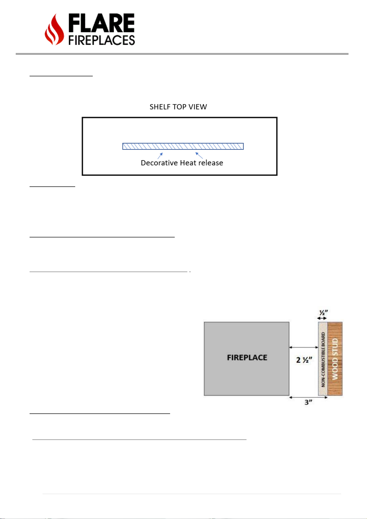
73 | P a g e
6. Fireplace shelf enclosure – The minimum height to the inside of a shelf above the fireplace is 6 inches (12 inches above the
glass). The shelf must be built with non-combustible material at least 5/8” thick. Due to the low size of shelf enclosure, it is
recommended to build the enclosure using a Skamol board. The Skamol board is a light non-combustible material that can
help prevent the formation of cracks and is a good insulator. The shelf enclosure MUST comply with Flare heat release
requirements.
7. Ceiling Clearance-
The minimum ceiling height for a Flare Fireplace is 40”
The heat release above the fireplace is critical for keeping the chase and surrounding walls at a relatively
low temperature.
8. Minimum clearance to sides and back - Non-combustible – The minimum clearance from the back and sides of the
fireplace to any non-combustible material (i.e., cement board or Type X fire rated board) is 2 inches. This clearance allows
for proper air flow.
9. Minimum clearance to sides and back – Covered combustible - Combustible material at the back or sides of the fireplace,
MUST be covered with non-combustible material that is at least ½ inch thick.
Covered wood can be placed a minimum 3” away from the side and back.
Example: A non-combustible cement board is placed 2 ½” inches
from the back of the fireplace. The cement board used is ½” inch
thick. Combustible material can be used behind cement board as
it is a total of 3 inches away from the back of the fireplace and is
covered with a non- combustible material.
10. Minimum clearance to sides and back – Combustible – Clearance to combustible material at the back or sides of the
fireplace, below the non-combustible line is 8”. Please note this does not include minimum clearance directly above the
fireplace inside the chase. Please see items starting at 12.
11. Minimum clearance directly above the fireplace inside the chase – non-combustible – All non-combustible studs to be
installed a minimum of ½” away from the fireplace. Metal studs should not connect to the fireplace or touch the fireplace.
Doing so will result in heat transfer from the fireplace to the metal stud. Make sure not to block hot air flow to the heat
release.

74 | P a g e
12. Minimum clearance directly above the fireplace inside the chase – Combustible
• First 18” directly above the fireplace MUST be framed using non-combustible material. Metal Studs. Zone A
• All combustibles above the 18” must be covered. Zone B.
There should be no combustible materials left uncovered above the fireplace inside the chase.
Fireplace chase should be designed and built to allow hot air to release from the unit and rise-up in a non-combustible
channel to the heat release.
13. Chase celling- Top of the chase must be covered with noncombustible material (Firestop). No exposed combustible
materials are allowed inside the chase.

75 | P a g e
14. Hearth Clearances –
A. Clearance to an uncovered combustible hearth below the glass is 2 inches as seen in EXAMPLE 1
B. When bringing your hearth to glass height it must be non-combustible for the first 7” extending from the glass
before any combustible material can be used to finish the hearth. As seen in EXAMPLE 2
15. Adjacent Wall 1 – Distance to any side adjacent wall must be at least 7 inches from the glass. As seen in EXAMPLE 1
EXAMPLE 1
EXAMPLE 2
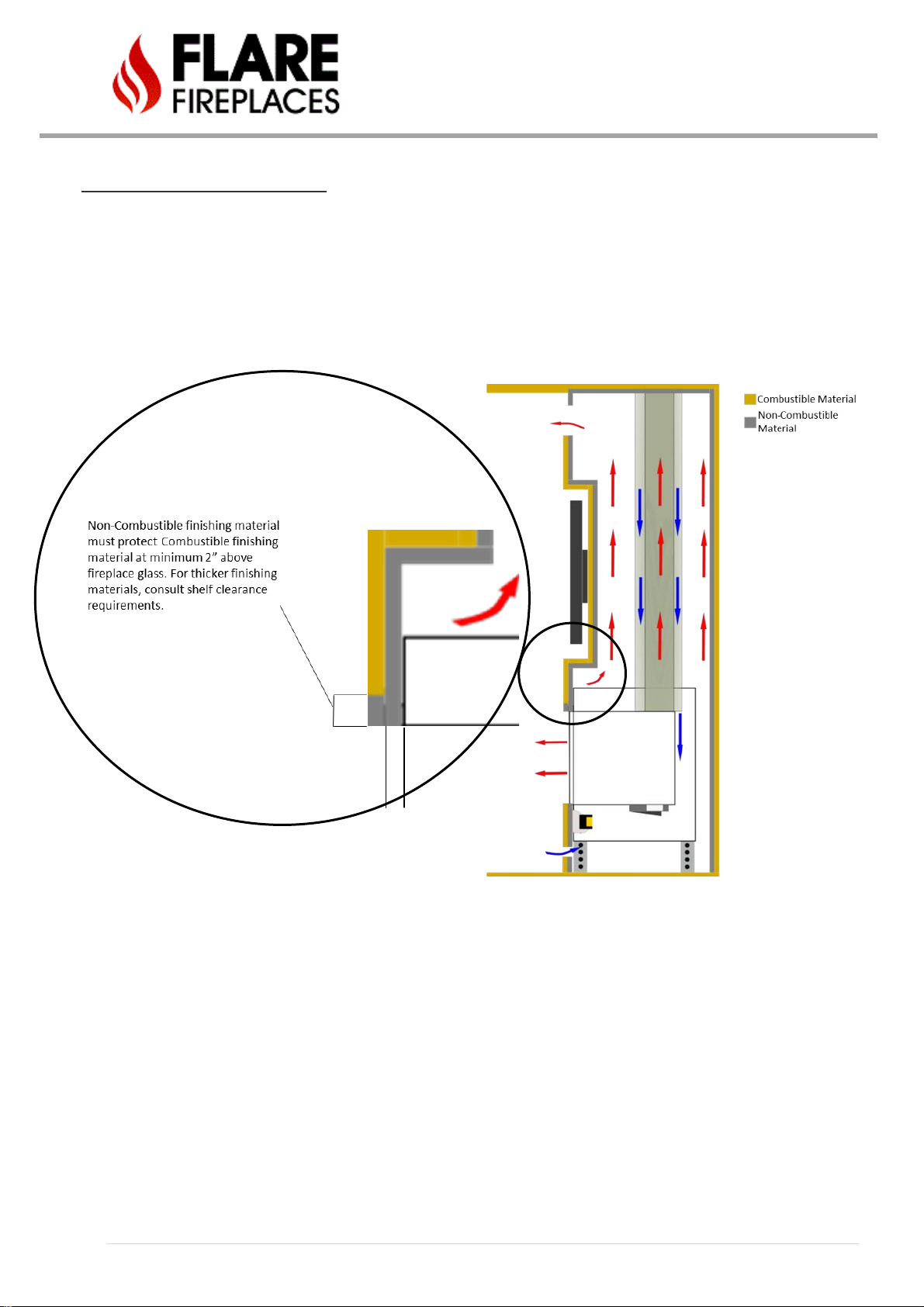
76 | P a g e
16. Finishing around front of the fireplace - Non-combustible finishing material (i.e., cement board, brick, stone, tile &
minimum ½” inch Type X fire rated drywall) MUST be used to finish around the front of the appliance. Covered
combustible material, can be used to finish around the fireplace, if the proper distance from the fireplace is maintained.
Use example below to find proper distance. See Examples 1 & 2 below for further details.
EXAMPLE 1

77 | P a g e
DO NOT connect materials to or drill into the metal fireplace frame. This can result in excessive heat transfer and/or
damage to the fireplace and surrounding materials.
EXAMPLE 2

78 | P a g e
CLEARANCES SPECIFICATION
Non-Combustible Materials Specification
Material which will not ignite and burn. Such materials are those consisting entirely of steel, iron, brick, tile, concrete, slate,
glass or plasters, or any combination thereof. Materials that are reported as passing ASTM E 136, Standard Test Method for
Behavior of Materials in a Vertical Tube Furnace at 750 ºC shall be considered non-combustible materials. Non-combustible
cement board approve must be at least 1/2” (13 mm) thick.
Non-combustible material may be installed on the fireplace frame to cover the metal part as detailed in the installation
examples and clarifications only if there is no weight transfer to the fireplace. Facing and/or finishing materials must never
overhang into the glass opening.
DO NOT connect materials to or drill into the metal fireplace frame. This can result in excessive heat transfer and/or damage to
the fireplace and surrounding materials.
All joints between the finished wall sheathing and the appliance must be sealed with non-combustible materials.
WARNING! Risk of Fire! DO NOT apply combustible materials beyond the minimum clearances. Comply with all minimum
clearances to combustibles as specified in this manual.
Examples of noncombustible materials to be used:
• Skamol Skamotec
• Promat PROMAFOUR System 1/2”/12 mm, 5/8”/15 mm, 3/4”/18 mm
• James Hardie - Hardiebacker® 1/2” Cement Board
• 5/8” Type X fire rated drywall. Type X gypsum board must comply with ASTM C1396 specification. Type X fire rated
gypsum board can be used around the fireplace or at the back as a non-combustible material.
Combustible Materials Specification
Materials made of or surfaced with wood, compressed paper, plant fibers, plastics, or other material that can ignite and burn,
whether flame-proofed or not, or plastered or un-plastered shall be considered combustible materials.

79 | P a g e
MANTEL CLEARANCE
Combustible mantel clearance can vary per the mantel size and location. Use chart and provided table for
information on mantel install. Do not anchor any mantel or shelf to the fireplace. Only use metal studs
above the fireplace as anchor points. Non-combustible mantels do not have a minimum clearance to the
fireplace opening and can be brought as close to the glass as allowed by the frame of the fireplace. Please
keep in mind any material used could potentially heat up dramatically the closer to the fireplace you bring
it and the longer the fireplace is on.
Mantel Clearance table and example
REF
Height
Mantel Depth
A
2"
1"
B
4"
4"
C
6"
6"
D
10"
12"
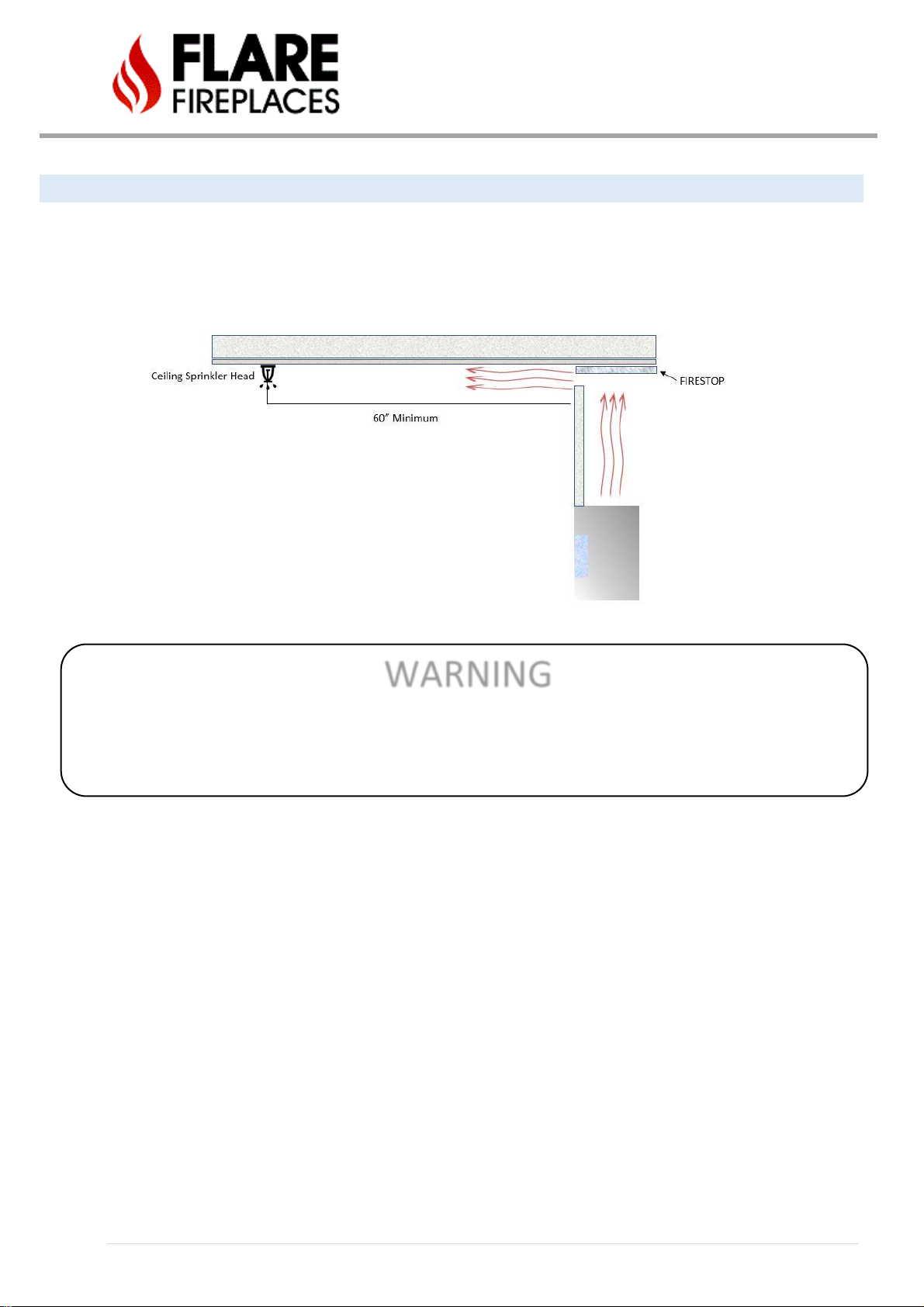
80 | P a g e
CLEARANCE TO SPRINKLER
In a situation where a sprinkler head is installed within proximity to a Heat Release, the diagram below MUST be followed. The
distance between the sprinkler head & Heat Release opening cannot be less than 60” in length at every point from the origin of
the Heat Release. You must also verify the sprinkler head sensor is set to the proper heat setting so it does not activate when
the room heats up from the fireplace being operated normally. DO NOT INSTALL A SPRINKLER IN THE FIREPLACE CAVITY.
Please follow local building code to determine what temperature setting is relevant for your installation.
WARNING
VAULTED CEILINGS CAN CREATE A CHANEL THAT FUNNELS HOT AIR DIRECTLY TOWARDS A SPRINKLER HEAD PLACED AT THE
PROPER DISTANCE FROM HEAT RELEASE, AS STATED ABOVE. IF SPRINKLER HEAD SENSOR IS NOT RATED FOR HIGH HEAT IT
COULD POTENTIALLY SET OFF THE SPRINKLER SYSTEM INADVERTENLY. PLEASE WORK WITH BUILDER & INSPECTOR TO VERIFY
YOUR SPRINKLER SYSTYEM IS PROPERLY SET TO ACCOMMODATE HIGHER TEMPERATURES & IS NOT SET UP IN A HEAT CHANEL

81 | P a g e
HE AT RELEASES
All Flare Fireplaces (both safety screen and double glass units) require heat releases for warm air to flow back into the room.
This controls the temperature of the surrounding walls, keeping them relatively cool.
Top Hot Release - The release/ outlet for hot airflow from the wall enclosure MUST remain OPEN. The outlet must be at the top
part of the enclosure but not necessarily at the front, so long as the measurements below are maintained. Heat release opening
can be installed at the sides of the enclosure (one on every side), back or on top of (in case of a drop wall design).
For fireplaces sized 80” & 100”– vent area must be at least 200 square inches OPEN AIR FLOW.
For fireplaces sized 60” & 70” - vent area must be at least 140 square inches OPEN AIR FLOW.
For fireplace sized 50” and below - vent area must be at least 100 square inches OPEN AIR FLOW.
The top of the outlet(s) must be at least 1” (25mm) down from the ceiling firestop, and no more than 3” (76mm) down. The
vent can also be installed on top of the enclosure, as a drop wall (a chase that is not built all the way to the upper ceiling). Any
opening greater than the minimum size is highly recommended and will help reduce the temperature of the surrounding
walls. Make sure a non-combustible fire stop is placed atop the inside of the chase and is framed in a way that does not
allow any pockets of heat to be formed. All rising heat should be able rise to the fire stop and freely flow though the heat
release opening into the room.
AIR INTAKE
Required for installation with double glass or safety screen with optional blower kit. This allows air circulation which cools the
external glass and increases the efficiency of the fireplace. See diagram on page 63. These relatively quiet blowers cannot be
turned off and are required for the continued operation of your Double Glass system.
Lower Air Intake - Optional for normal safety screen installation. Required for installation with double glass or safety screen
with optional blower kit.
For fireplaces sized 80” & 100” – vent area must be at least 100 square inches OPEN AIR FLOW.
For fireplaces sized 60” & 70” - vent area must be at least 70 square inches OPEN AIR FLOW.
For fireplaces sized 50” and below - vent area must be at least 50 square inches OPEN AIR FLOW.
FOR SEE THROUGH FIREPLACES THE AIR INTAKE REQUIREMENTS ARE DOUBLE, EQUAL ON BOTH SIDES.
NOTE: Openings above for Heat Release and Air Intake are measured for open air space. The fans for the Double Glass cannot
be turned off during operation.
Lower vent opening can also be used as an access door to the gas valve if it meets both requirements in terms of size. Lower
vent opening can be installed at the sides of the enclosure (one on every side), back or front. It is recommended to place one
opening on either side of longer units, to allow for better distribution across all fans of air taken in from the bottom.
NOTE
***VERTICALLY ORIENTED HEAT RELEASES ARE NOT ACCEPTABLE, AND WILL LEAD TO OVERHEATING***
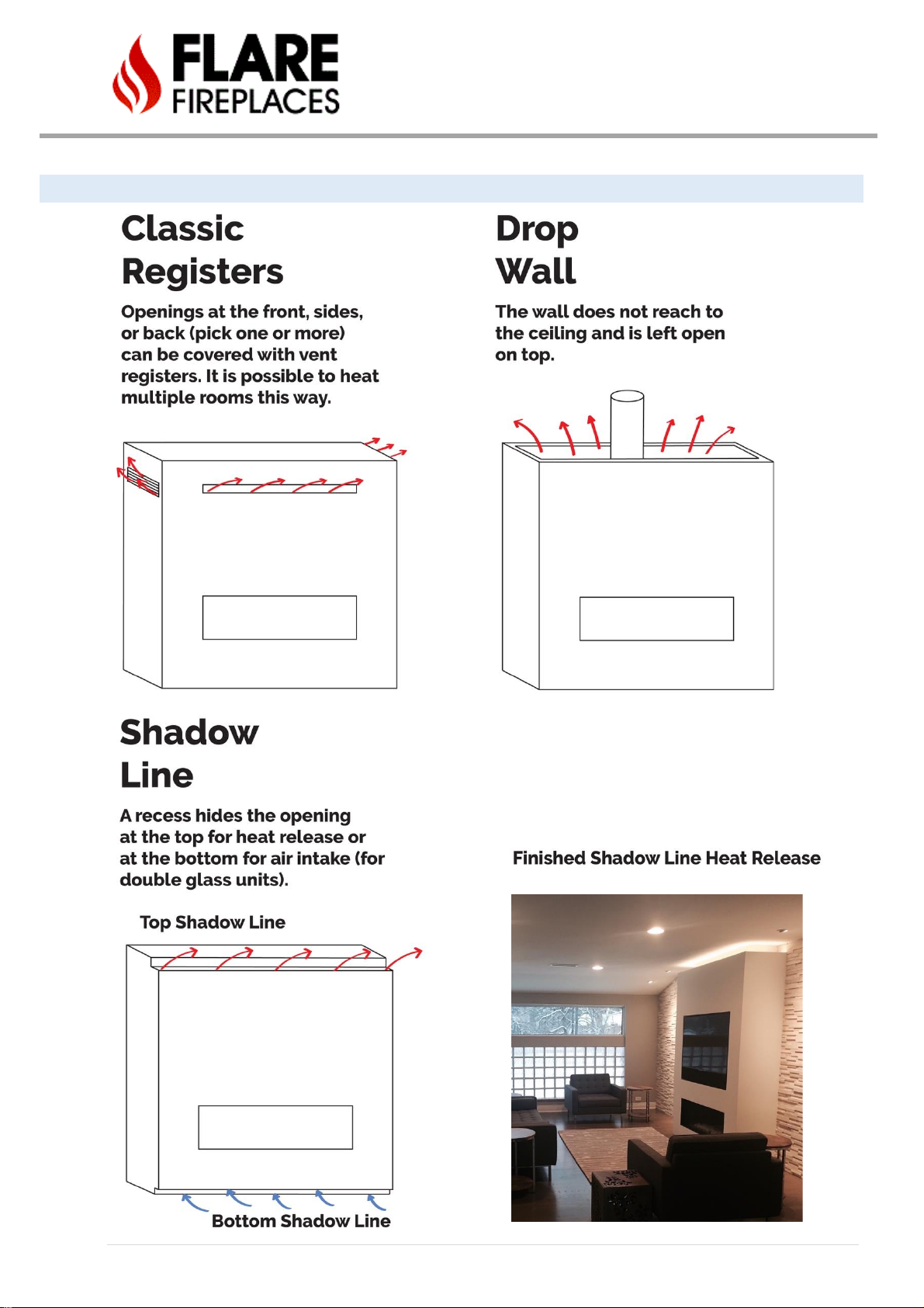
82 | P a g e
EXAMPLES OF HEAT RELEASES

83 | P a g e
SETTING UP YOUR FLARE FIREPLACE FOR ENHANCED OPERABILITY
The Flare Fireplace is a finely tuned machine that operates at the highest of standards. To get the most out of your Flare
Fireplace installation please see the following suggestions for optimal performance and functionality.
KEEPING THE WALL ABOVE YOUR FIREPLACE AS COOL AS POSSIBLE
The Flare Fireplaces installation guide calls for, and clarifies, the minimum requirements for a heat release in your build to make
sure your fireplace operates within the safely set nationwide guidelines for direct vent fireplaces. To make sure the wall above
your Flare Fireplace is as cool as possible, Flare suggests enlarging your heat release to increase how fast the heat created in your
fireplace cavity is evacuated into the space. The faster heat can evacuate the cavity above your fireplace the cooler your wall will
be. Flare offers many ways to implement a heat release that mask its existence, allowing you to increase its size dramatically
without ruining the visual aesthetic (SEE SECTION REFERENCING EXAMPLES OF HEAT RELEASES AND AIR INTAKES IN FLARE
INSTALLATION MANUAL). For example, if you are installing a Flare Fireplace with a 50” length you will need a minimum of 100 SQ “
of open-air flow to evacuate your cavity successfully. But by meeting the minimum specification allowed, the wall temperatures
will remain safe but at the higher end of the spectrum allowed for these style fireplaces. By implementing a shadow line heat
release as close as 3” from your ceiling you can increase the opening by more than double to create a cavity that evacuates heat at
a much faster rate. Allowing for a wall that reaches temperatures well below the minimum standard required for safe operation.
SHADOW LINE FRAMING
EXAMPLE 3” FROM CEILING
COMPLETED SHADOW LINE
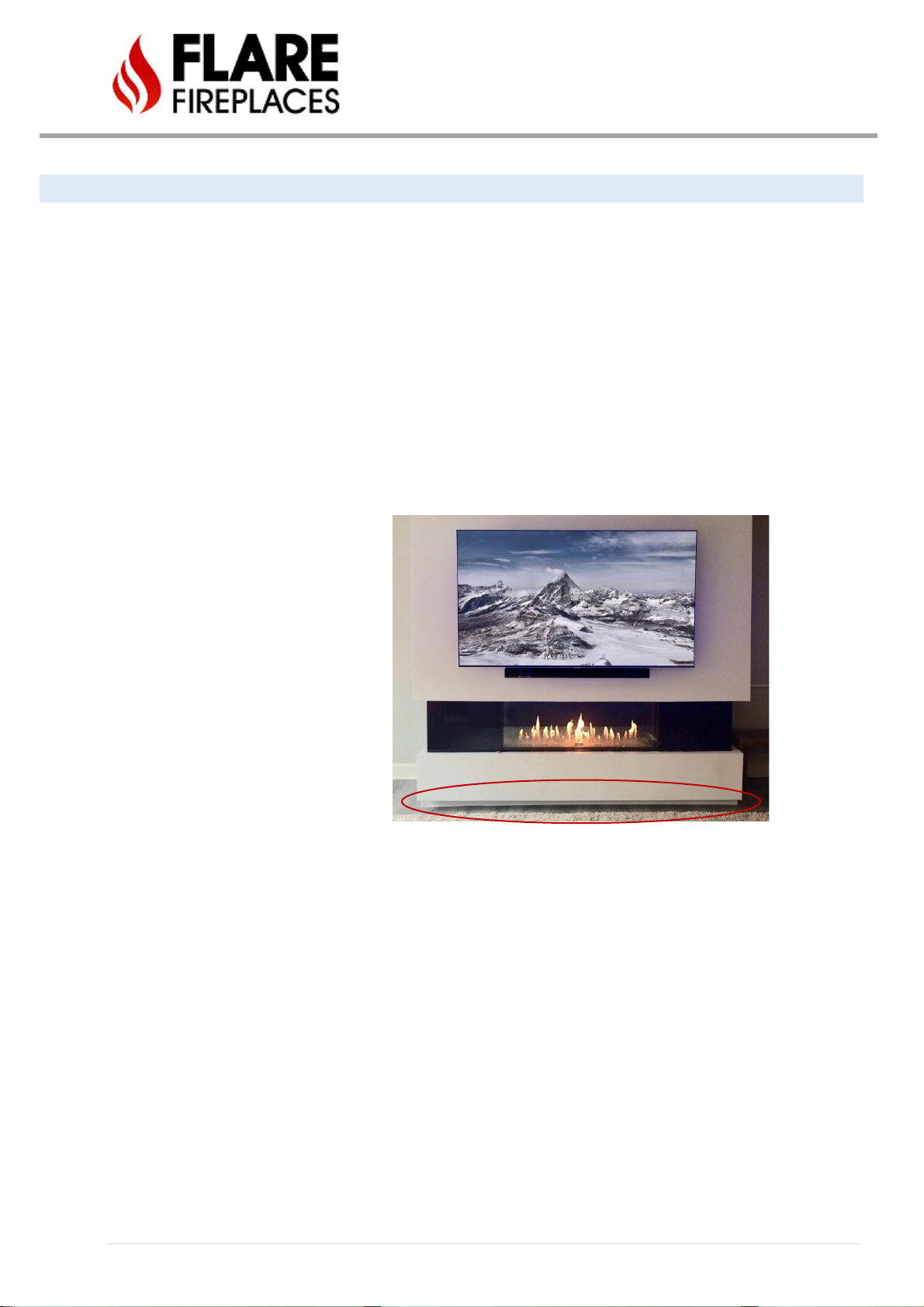
84 | P a g e
KEEPING YOUR DOUBLE GLASS AS COOL AS POSSIBLE
The Flare Fireplaces installation guide calls for, and clarifies, the minimum requirements for the air intake sizing on your double
glass fireplace build, making sure your fireplace operates within the safely set nationwide guidelines for direct vent fireplaces. To
get the outer layer of glass on your double glass equipped Flare Fireplace as cool as possible, Flare suggests enlarging your air
intake to increase the amount of room temperature air being pulled in between the two panes of double glass. The more room
temperature air the silent intake fans can pull between the two panes of Double Glass, the cooler your outer layer will be. Flare
offers many ways to implement an air intake that mask its existence, allowing you to increase its size dramatically without ruining
the visual aesthetic (SEE SECTION REFERENCING EXAMPLES OF HEAT RELEASES AND AIR INTAKES IN FLARE INSTALLATION
MANUAL). For example, if you are installing a Flare Fireplace with a 50” length you will need a minimum of 50 SQ “ of open-air flow
to cool your double glass successfully. But by meeting the minimum specification allowed, the glass temperatures will remain safe
but at the higher end of the spectrum allowed for these style fireplaces. By implementing a shadow line air intake (ALSO KNOWN
AS A FLOATING HEARTH) as close as 3” from your floor, you can increase the opening by more than double to create a cavity that
evacuates heat at a much faster rate. Allowing for an outer layer of glass that reaches temperatures well below the minimum
standard required for safe operation.
AIR INTAKE INSTALLED AS FLOATING
HEARTH. PANEL IN FLOATING HEARTH
THAT IS PARALLEL TO THE FLOOR IS WIDE
OPEN, ALLOWING FOR MUCH MORE AIR
FLOW
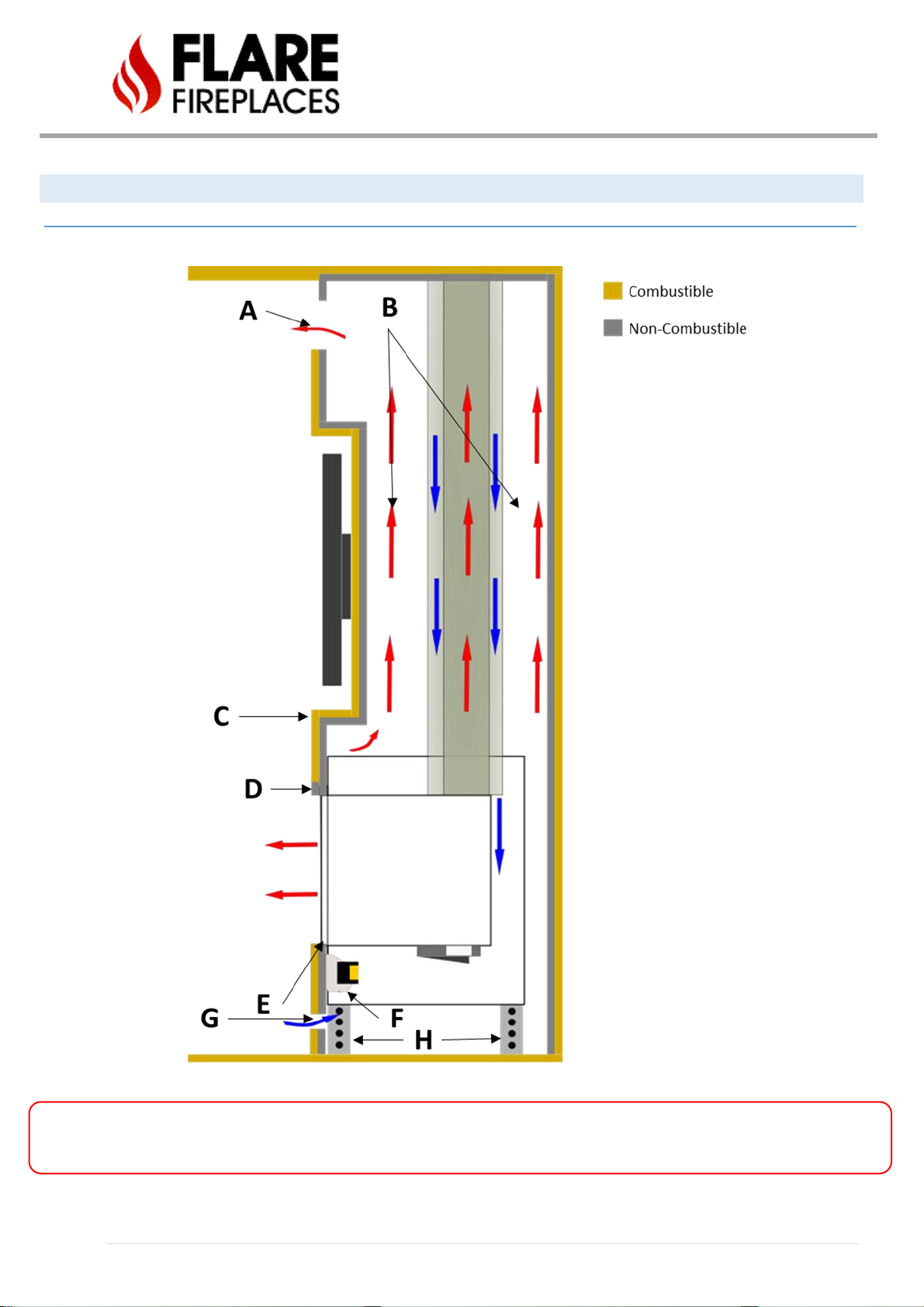
85 | P a g e
FLARE FRONT, SEE THROUGH, AND CORNER FIREPLACE CLEARANCE
FLAT – SIDE AND ISOMETRIC VIEW
Warning! – Maintain open Air flow between the fireplace and drywall. Make sure cables or any other materials are not blocking
hot air flow.

86 | P a g e
A. Top Vent system - Hot Airflow outlet from the wall enclosure MUST remain open. The outlet must be at the top part of
the enclosure, but not necessarily at the front, if the measurements below are maintained.
For fireplaces sized 80” & 100”– vent area must be at least 200 square inches OPEN AIR FLOW.
For fireplaces sized 60” & 70” - vent area must be at least 140 square inches OPEN AIR FLOW.
For fireplace sized 50” and below - vent area must be at least 100 square inches OPEN AIR FLOW.
B. Open air flow for hot air to rise from the fireplace to the top of the enclosure. The enclosure can be supported by studs,
but open-air flow MUST be maintained at all time. In case needed, insulation for electric wires or systems may be added but
it is important to keep most of the air flow open. Never place any insulation on the fireplace.
C. Metal Stud below non-combustible material line. Below non-combustible line, all studs used should be metal type. No
studs to be connected to the fireplace frame (1/2 Inch clearance). Open hot airflow MUST be maintained and should not be
blocked. Note: Max recess of TV cavity should not exceed 6”. Recesses exceeding this dimension run the risk of creating a
shelf and hindering air flow above unit, resulting in a wall that may overheat.
D. Non-combustible material is placed flat on the front fireplace support bracket. The support bracket holds the fire-rated,
non-combustible, material and allows hot air to rise from the glass into the fireplace enclosure. Hot air is to be released into
the room using the top static vent opening.
The fireplace enclosure must allow air to rise and circulate from the top of the fireplace glass (from lower vent opening), to
be released back to the room from the top.
To increase heating, the enclosure should prevent hot air from being released to the attic by venting it back to the room
using the static vent system (A).
Non-combustible stud MUST NOT be connected or drilled into the fireplace frame. Drilling into the fireplace frame can result
in damage to the fireplace.
E. Cold air, drafted from the room through the lower static vent, (G) flows up and is heated by the fireplace. The Cold air gap
should remain open to allow air to flow up and exchange heat with the fireplace. The fireplace can be installed with double
glazing glass system or safety screens. Blower system may be used to push cold air up (F).
F. Heat exchange blowers are optional when fireplace is installed with safety screens. Heat exchange blowers must be
included when installing a double-glazing fireplace. The blowers are designed to move cold air from the room using the
lower vent opening (G) up against the fireplace glass. As the air flows on the glass, it is heated and released back to the room
from the glass front and from the top (A) vent opening.
G. Lower vent opening. OPTIONAL for normal installation. A MUST for double glass installation or blower kit option.
For fireplaces sized 80” & 100” – vent area must be at least 100 square inches OPEN AIR FLOW.
For fireplaces sized 60” & 70” - vent area must be at least 70 square inches OPEN AIR FLOW.
For fireplaces sized 50” and below - vent area must be at least 50 square inches OPEN AIR FLOW.
FOR SEE THROUGH FIREPLACES THE AIR INTAKE REQUIREMENTS ARE DOUBLE, EQUAL ON BOTH SIDES.
H. Adjustable fireplace legs.
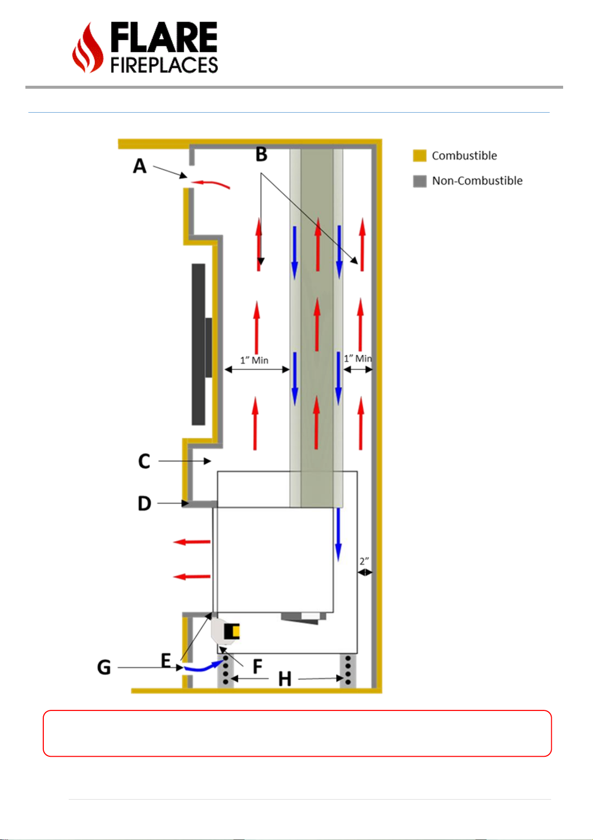
87 | P a g e
L SHAPE – SIDE AND ISOMETRIC VIEW
WARNING! Maintain open air between the fireplace and drywall. Make sure cables or any other materials are not
blocking hot air flow.

88 | P a g e
A. Top Vent system - Hot Airflow outlet from the wall enclosure MUST remain open. For Flare See Through fireplace, open
vent must exist in both sides of the glass. The outlet must be at the top part of the enclosure but not necessarily at the front
if the measurements below are maintained.
For fireplaces sized 80” & 100”– vent area must be at least 200 square inches OPEN AIR FLOW.
For fireplaces sized 60” & 70” - vent area must be at least 140 square inches OPEN AIR FLOW.
For fireplace sized 50” and below - vent area must be at least 100 square inches OPEN AIR FLOW.
B. Open air flow for hot air to rise from the fireplace to the top of the enclosure. The enclosure can be supported by studs,
but open-air flow MUST be maintained at all time. In case needed, insulation for electric wires or systems may be added but
it is important to keep most of the air flow open. Never place any insulation on the fireplace.
C. Metal Stud below non-combustible material line. Below non-combustible line, all studs used should be metal type. No
studs to be connected to the fireplace frame (1/2 Inch clearance). Open hot airflow MUST be maintained and should not be
blocked. Note: Max recess of TV cavity should not exceed 6”. Recesses exceeding this dimension run the risk of creating a
shelf and hindering air flow above unit, resulting in a wall that may overheat.
D. Non-combustible material is placed flat on the front fireplace support bracket. The support bracket holds the fire-rated,
non-combustible, material and allows hot air to rise from the glass into the fireplace enclosure. Hot air is to be released into
the room using the top static vent opening.
The fireplace enclosure must allow air to rise and circulate from the top of the fireplace glass (from lower vent opening), to
be released back to the room from the top. To increase heating, the enclosure should prevent hot air from being released to
the attic by venting it back to the room using the static vent system (A).
Non-combustible stud MUST NOT be connected or drilled into the fireplace frame. Drilling into the fireplace frame can result
in damage to the fireplace.
E. Cold air, drafted from the room through the lower static vent, (G) flows up and is heated by the fireplace. The Cold air gap
should remain open to allow air to flow up and exchange heat with the fireplace. The fireplace can be installed with double
glazing glass system or safety screens. Blower system may be used to push cold air up (F).
F. Heat exchange blowers are optional when fireplace is installed with safety screens. Heat exchange blowers must be
included when installing a double-glazing fireplace. The blowers are designed to move cold air from the room using the
lower vent opening (G) up against the fireplace glass. As the air flows on the glass, it is heated and released back to the room
from the glass front and from the top (A) vent opening.
G. Lower vent opening. Optional for normal installation. A Must for double glass installation or blower kit option.
For fireplaces sized 80” & 100” – vent area must be at least 100 square inches OPEN AIR FLOW.
For fireplaces sized 60” & 70” - vent area must be at least 70 square inches OPEN AIR FLOW.
For fireplaces sized 50” and below - vent area must be at least 50 square inches OPEN AIR FLOW.
FOR SEE THROUGH FIREPLACES THE AIR INTAKE REQUIREMENTS ARE DOUBLE, EQUAL ON BOTH SIDES.
H. Adjustable fireplace legs.
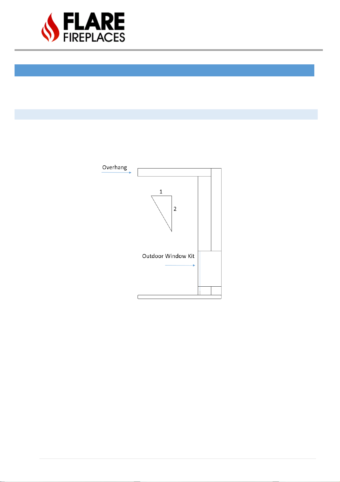
89 | P a g e
INDOOR/OUUTDOOR KIT
The following installation information is used for the Flare Fireplace outdoor kit. The outdoor window kit can only be used with
Flare Front and Flare See Through. The Flare outdoor kit is installed like a window. The fireplace is then installed next to the
outdoor window kit. All fireplace clearances must be followed when installing a Flare Fireplace next to a window kit.
APPLIANCE LOCATION
• The Fireplace needs to be installed in a weatherproof enclosure. The Fireplace outdoor kit is made from stainless steel and
is weatherproofed from the front glass only. The Fireplace must be installed in a weatherproof enclosure from the top,
side and bottom.
• Overhang requirement. Weatherproof overhang in front of fireplace is 1/2 of the height of the overhang measured from
the base of the unit.
• All the fireplace controls and gas components need to be installed in a weatherproof enclosure.
• The outdoor kit will tolerate moderate amounts of water on an occasional basis but is not waterproof. The fireplace must
be enclosed in a weatherproof enclosure covered in typical weatherproof material, such as siding/ stucco/stone/tile, etc.
and have a weatherproof structure to shed water that extends horizontally beyond the front and side perimeter of the
fireplace. Water running down vertical surfaces should be directed away from the fireplace using flashings. Measures must
be taken to ensure any accumulated water drains away from the fireplace and structure. When the fireplace is installed on
surfaces where water may collect or cause damage, a suitable drainage pan should be placed under the unit and the water
drained away.
• Do not use the remote-controlled handset supplied with the appliance. The use of the thermostat on the remote may
result in continued operation of the fireplace.
• Exposure to outdoor sun - Exposure to outdoor sun light will cause some painted finishes to fade over time. Fading is
unavoidable and not covered under warranty. Minimize fading by installing the fireplace away from direct sunlight.

90 | P a g e
• Make sure the fireplace is fully turned off when attempting to clean the front of the fireplace (including
pilot).
• Use the Flare architectural guide for information on the window size and opening:
http://flarefireplaces.com/portfolio-items/flare-outdoor/

91 | P a g e
• All studs and surrounding should follow the
fireplace clearances and non-combustible
requirements.
• The outdoor window kit should be sealed with non-
combustible tape prior to covering with brick or
stucco.
92 | P a g e
BURNER DIMENSIONS
***For updated product dimensions and framing information, please visit Flare’s PRODUCT PAGE, navigate to the product of
your choice, scroll to four tabbed charts, & click “DOWNLOAD CENTER”. ***
BURNER TYPE
SIZE (cm)
SIZE (in)
FIREPLACE SIZE
# OF BURNERS
A
55 cm
21 11/16"
30" 1 B
80 cm
31 12/16"
45" 1 C
105 cm
40 1/16"
50" 1 D
125 cm (35 cm, 55 cm, 35 cm)
50 1/16" (14", 22", 14")
60" 3 E
150 cm (35 cm, 80 cm, 35 cm)
59 15/16" (14", 32", 14")
70" 3 F
175 cm (35 cm, 105 cm, 35cm)
68 4/16" (14", 40", 14")
80" 3 G
215 cm (55 cm, 105 cm, 55 cm)
84" (22", 40", 22")
100"
3
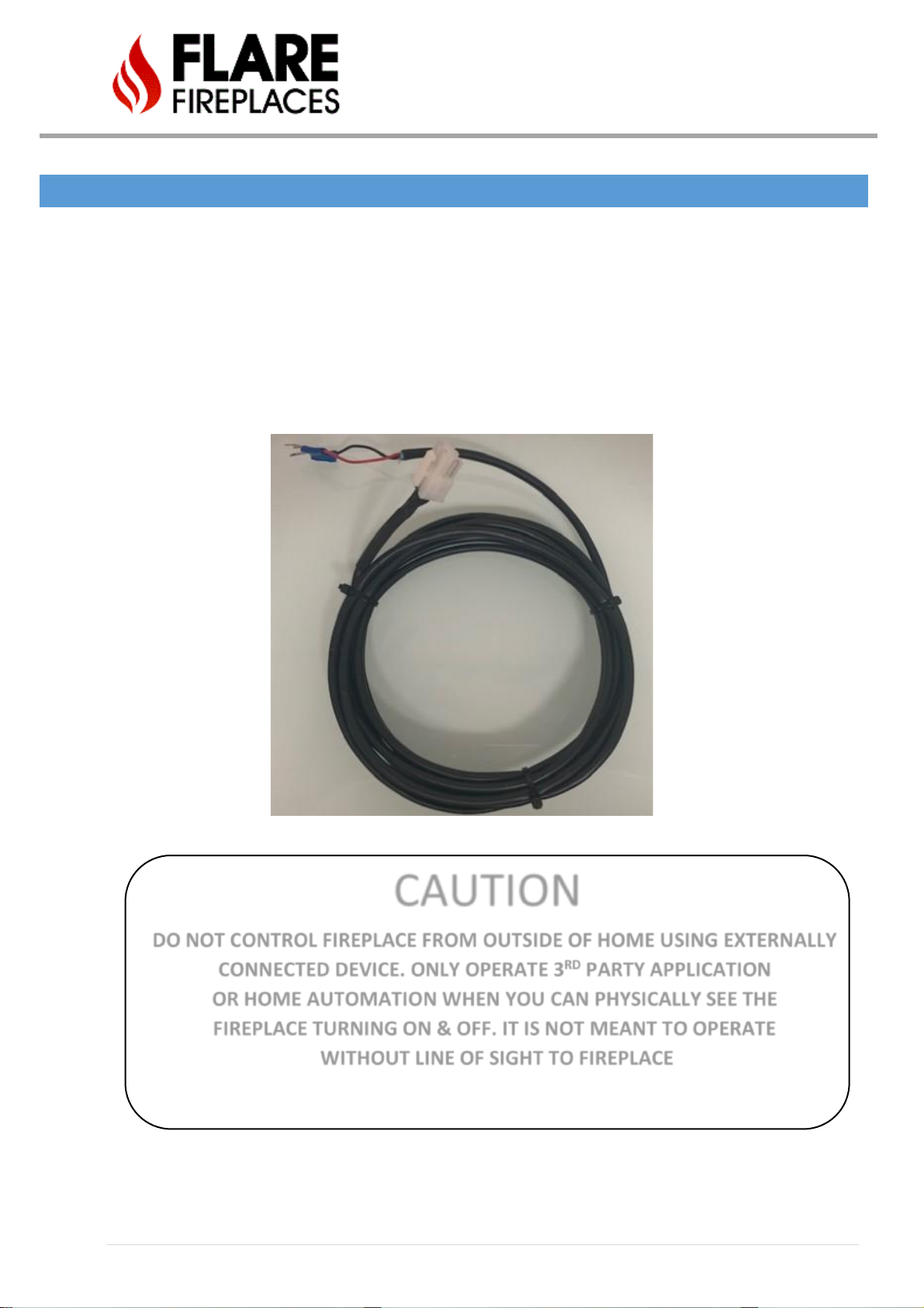
93 | P a g e
HOME AUTOMATION
The Flare Fireplace can be operated through an external source (See cautionary remark below) such as a smart home
(home automation) system by using the 6- pin connector on the receiver X8 port in place of the Wall Switch.
The Flare Home Automation Cable (below) must be used between the Flare receiver and the home automation
system. Position the home automation system so that the Flare Home Automation Cable can be connected directly.
The Flare Home Automation Cable can be identified by simply removing the Flare wall switch from the wire provided.
This wire can be extended up to 80 FT for integration into a new or existing Home Automation System. Please contact
Flare Support for additional information on appropriate relays to be used.
CAUTION
DO NOT CONTROL FIREPLACE FROM OUTSIDE OF HOME USING EXTERNALLY
CONNECTED DEVICE. ONLY OPERATE 3RD PARTY APPLICATION
OR HOME AUTOMATION WHEN YOU CAN PHYSICALLY SEE THE
FIREPLACE TURNING ON & OFF. IT IS NOT MEANT TO OPERATE
WITHOUT LINE OF SIGHT TO FIREPLACE

94 | P a g e
ELECTRIC AND CONTROL
ELECTRIC DIAGRAM - SCREEN
- Wall switch/Home Automation connects directly to X8 port.
- X4 port is always closed circuit.
- SIT 110v will be powered by home wall socket.
X1: Green= Ground
White= Common
Black= Line

95 | P a g e
DIAGRAM – DOUBLE GLASS AND POWER VENT
• Aux port(X13) is used as switch to open and close the relay port of the control
system (To activate and deactivate the control system)
• ON/OFF switch(X4) are controlled via the Flare Control system
Optional 110V to
Power to LED System

96 | P a g e
DOUBLE GLASS BOARD & LED LIG HT GUIDE
FAN BYPASS SWITCHES & LEDs
(***NUMBER OF FANS CAN CHANGE BASED ON MODEL SIZE***)
The dipswitches (DSW1&DSW2), in the “FAN BYPASS” area of the Double Glass Board, are used to determine what fans will
be monitored by the board, verifying all fans are indeed working properly before allowing the fireplace burner to start. Turn
the switch ON ↑(UP) to bypass monitoring of fan number of your choice, & OFF ↓(DOWN) to begin to monitor fan activity. If
no fan is present, set switch to on so it will bypass the need to verify fan activity. The switches are numbered to correlate with
the LED lights they are associated with above.
The third Dipswitch is the “Master Bypass (PV, Relay, Fan)” dipswitch. Representing 4 switches 1-3 are used and the 4th switch
is not used.
Switch 1: is used to determine if the system has PV or not, Turn the switch ON ↑(UP) to bypass monitoring of PV system, &
OFF ↓(DOWN) to begin to monitor PV system.
Switch 2: is used to Bypass the relay to the Board so that the board will begin work directly when get 110v no matter if the
system has relay or not, Turn the switch ON ↑(UP) to bypass the relay, & OFF ↓(DOWN) to wait for relay command from the
user.
Switch 3: representing the master Bypass for all, turning this ON↑ bypasses all check to the fan system & Power Vent, OFF↓
will monitor the whole system.
Switch 4: is not used.
FAN LED INDICATORS
A. Red - Fan is not connected or malfunctioning.
B. Off - Fan is being bypassed.
C. Green - Fan is running properly.
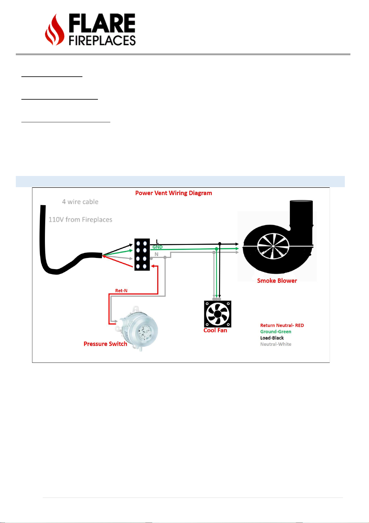
97 | P a g e
POWER LED INDICATOR
The Red Power LED lets you know the board is receiving power.
POWER VENT LED INDICATOR
The Blue Power Vent LED lets you know the Power Power-Vent is properly sending & receiving signal to the board.
FAN & POWER VENT REQUEST LED
The White LED indicates the USER has requested to start the fans & Power Vent, if connected.
ELECTRIC DIAGRAM – PV SYSTEM
4 wire cable
110V from Fireplaces

98 | P a g e
REPLACEMENT PARTS
See below for flare replacement part list.
• Please contact your fireplace dealer to purchase any replacement part.
• Please make sure to provide the description and part number.
• Please make sure to use a certified installer for any service related to your fireplace.
FLARE FIREPLACES SIT PARTS LIST
PART NAME
DESCRIPTION
SIT-Full Gas System
Gas Valve System, Receiver, SIT Wiring
SIT-Valve NG
Natural Gas Valve for SIT System
SIT-Valve LP
Liquid Propane Gas Valve for SIT System
SIT-Remote
Remote for SIT System
SIT-Receiver
Receiver for SIT System
SIT-Wall Switch X-8
Wall Switch for SIT System
SIT-Data X-5 Cable
Data Cable for SIT System
SIT- Ground Cable
Ground Cable for SIT System
SIT- Control Board
Main Control Board for SIT System
SIT-110 X-1 Cable with Molex
SIT Double Glass Adapter Wiring Harness with Molex
SIT- 110 X-1 Cable
SIT Screen Adapter Wiring Harness
SIT-Relay X-4 Cable
Relay Cable for SIT System
SIT-Pilot Assembly NG
Natural Gas Pilot assembly for SIT System
SIT-Pilot Assembly LP
Liquid Propane Pilot Assembly for SIT System
SIT-Spark Cable
Ignition Cable for SIT System
SIT-NG Motor
Natural Gas Motor for SIT Gas Valve
SIT-LP Motor
Liquid Propane Motor for SIT Gas Valve
SIR-Jumper x-4
Relay Jumper for SIT System
SIT-DG Relay Kit
Double Glass Relay Kit for SIT System
SIT Pilot Brass Compression Fitting
Brass Pilot Compression Fitting for SIT System
99 | P a g e
MAINTENANCE
• It is recommended that a qualified service technician perform a routine inspection at the beginning of each heating season.
• Disconnect power before attempting maintenance or repair of the fireplace.
• Installation and maintenance must be performed by an authorized qualified installer, service agency or gas supplier.
• Any safety screen or guard removed for servicing placed back before operating this appliance.
• DO NOT USE this appliance if any part has been under water. Immediately call a qualified service technician to inspect
the unit and to replace any part of the control system and any gas valve that has been under water or impacted.
• Any alteration to the product that causes soot or carbon to form and results in damage is not the responsibility of the
manufacturer.
• Do not modify or substitute any part of this appliance.
• Inspect the external vent cap on a regular basis to make sure that no debris, plants, trees, or shrubs are interfering with the
air flow.
• Do not operate the fireplace without the fireplace glass.
• It is imperative that control compartments, screens, or fans system for double glass be kept clean and free of obstructions.
These areas provide the air necessary for safe operation.
• Light the heater using the built-in igniter. Do not use matches or any other external device to light your heater.
• Never remove, replace, modify, or substitute any part of the heater unless instructions are given in this manual. All other
work must be done by a trained technician. Do not modify or replace orifices.
WARNING!

100 | P a g e
Yearly Service - Commercial fireplaces may need to be serviced more frequently depending on
usage.
Failure to inspect and maintain the fireplace may lead to improper combustion and a potentially dangerous situation.
We recommend the following procedures be done by a qualified technician.
Glass Maintenance
• Always use suction cups to remove the fireplace glass. Use the manual procedure for instruction on how to
remove the fireplace glass. Always use gloves when removing the glass to protect your hand and prevent
fingerprints on the glass.
• DO NOT USE abrasive cleaners on the glass panels. DO NOT ATTEMPT to clean the glass panels when they are
hot.
• Do not use normal household (usually ammonia-based) glass cleaners to clean the glass as these cleaners can
leave a permanent stain. Only a gas fireplace glass cleaner should be used.
• Verify no cracks or breakage in the glass.
• Place glass in a safe location to prevent breakage.
• Never attempt to operate the fireplace without the fireplace glass.
Pilot Maintenance
• Visually inspect the pilot flame. The pilot flame should be always present when the fireplace is in operation.
• Make sure the pilot flame has two flame tips pointing to the flame sensor (thermocouple) and to the center of the burner.
• Make sure the pilot area is clean from any dust, media or any other debris that may disrupt the operation of the ignition
system. Lint or foreign material must be removed with a brush or vacuum.
• Verify fireplace ignition using the remote or wall switch. Verify electronic ignition, sparking sequence, pilot operation and
burner ignition.
Burner Maintenance
• The flames from the burner should be visually checked. The flame should have a blue base and yellow tops and be candle-
like in appearance.
• If excessive soot is found inside the firebox area, the fireplace will require adjustment. Verify the air shutter and vent
restrictor setting and document any changes.
• If the flame becomes sooty, dark orange in color, or extremely tall, do not operate the heater.
• Measure gas pressure. Inlet _______ W.C., Outlet _______ W.C.
Vent Maintenance
The following venting system inspection by a qualified service technician is recommended every six months:
• Inspect for excessive condensation, e.g., water droplets forming in the inner lining and subsequently dripping out of the
joints. This can cause corrosion in the system.
• Check for corrosion in areas exposed to the elements. Where rust spots or holes have appeared, these must be immediately
replaced.
• Ensure that there is no foreign material in the vents. Survey by removing the cap and shining a light down the vent.
• Check all joints and pipes to make sure that nothing has been disturbed or loosened.
Double Glass Fans
• Disconnect power to the Flare control system.
• Remove the external glass and the covering trim.
• Inspect the fans around the Flare firebox and make sure they are all turning.
• Clean all fans with a brush and vacuum to remove any dust or debris.
• Inspect the lower fireplace intake. Clean the lower vent intake with a brush and vacuum any dust or debris.
• Connect back the Flare control power and press the Flare remote arrow down. Make sure all fans are working properly.
• Turn off the fans and install back the trim and glass.
 Loading...