

Page 1
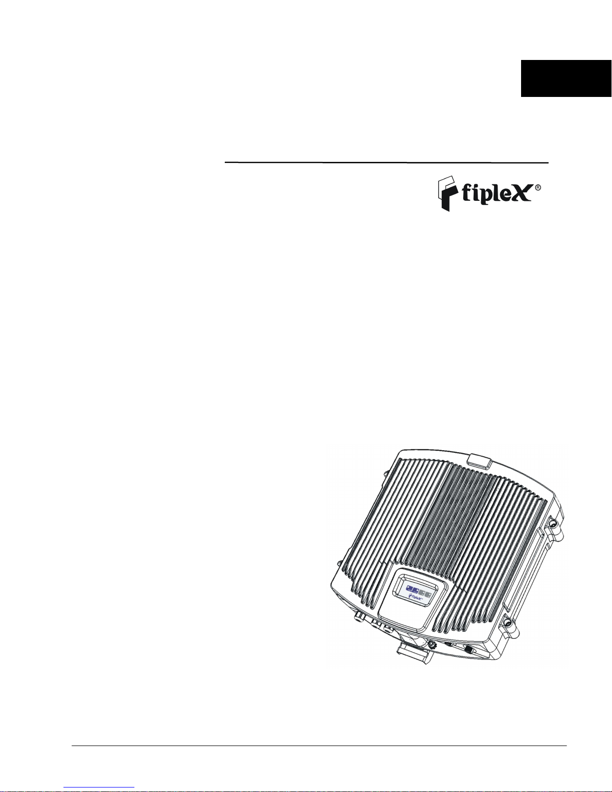
TETRA and UHF Compact Repeater
User & Installation Manual
English
English
EnglishEnglish
Page 2

Document History
Description Revision Date Issued
Preliminary release for early field trials 1.0 August 3rd, 2009
Indicator panel, and cabinet modifications 2.0 April 13th, 2010
Software screenshots updated 3.0 August 20th, 2010
UM-0100-03.09 – August 2010 II
Page 3

About this manual
This manual describes installation, commissioning, usage, function, operation and maintenance of Fiplex TETRA Compact
Repeater, UHF Compact Repeater and Fiplex portable Operational and Maintenance Software (pFOMS). The first part of
the manual describes the repeater hardware and the second part describes the software.
Hardware and software mentioned in this manual are subjected to continuous development and improvement. Consequently,
there may be minor discrepancies between the information in the manual and the performance and design of the hardware
and software. Specifications, dimensions and other statements mentioned in this manual are subject to change without
notice.
This manual or parts of it may not be reproduced without the written permission of Fiplex Europe SL.
Infringements will be prosecuted. All rights reserved.
Copyright © Fiplex Europe SL, Spain, 2009.
UM-0100-03.09 – August 2010 III
Page 4

Contents
Abbreviations................................................................................................................................. V
Part 1 HARDWARE..........................................................................................................................1
1. Safety....................................................................................................................................... 1
Dangerous Voltage Warning...................................................................................................... 1
Radiation Hazard Warning......................................................................................................... 1
FCC............................................................................................................................................... 1
R&TTE Compliance Statement.................................................................................................... 1
Station Ground ........................................................................................................................... 1
Electrostatic Discharge................................................................................................................ 1
Disposal of Electric and Electronic Waste................................................................................... 1
2. Product Description................................................................................................................. 2
Dimensions.................................................................................................................................. 3
3. Installation .............................................................................................................................. 4
Sitting the repeater .................................................................................................................... 4
Mounting .................................................................................................................................... 4
4. Commissioning ........................................................................................................................ 8
Connection.................................................................................................................................. 8
Starting operation ...................................................................................................................... 9
Status Indicators........................................................................................................................ 11
Automatic Gain Control (AGC)................................................................................................. 12
Overload Protection.................................................................................................................. 12
Laboratory Measurements........................................................................................................ 12
Part 2 SOFTWARE .........................................................................................................................13
5. Installation ............................................................................................................................ 13
6. Overview ............................................................................................................................... 19
General Tabsheet...................................................................................................................... 19
Status tabsheet ......................................................................................................................... 20
Configuration............................................................................................................................ 21
UM-0100-03.09 – August 2010 IV
Page 5

Abbreviations
AGC Automatic Gain Control
AMPS Advanced Mobile Phone Service
ARFCN Absolute Radio Frequency Channel Number
BCCH Broadcast Control Channel (GSM broadcast channel time slot)
BS Base Station, BS antenna = towards the base station
CDMA Code Division Multiple Access
DC Direct Current
DCS Digital Communication System (same as PCN)
DL Downlink signal direction (from base station via repeater to mobile station)
DPLX Duplex filter
EEPROM Electrical Erasable Programmable Read Only Memory
EGSM Extended Global System for Mobile communication
ETACS Extended Total Access Communication System
ETSI European Telecommunications Standard Institute
GSM Global System for Mobile communication
HW Hardware
LED Light Emitting Diode
LNA Low Noise Amplifier, uplink and downlink
MS Mobile Station, MS antenna = towards the mobile station
OMS Operation and Maintenance System
OL Overload
PA Power Amplifier
PCN Personal Communication Network (same as DCS)
PCS Personal Communication System
pFOMS Portable Fiplex Operation and Maintenance Software
PS Power Supply
RF Radio Frequency
RSSI Received Signal Strength Indication
SW Software
TDMA Time Division Multiple Access
UL Uplink signal direction (from mobile station via repeater to base station)
WEEE Waste of Electric and Electronic Equipment
UM-0100-03.09 – August 2010 V
Page 6
Part 1 HARDWARE
1. Safety
Dangerous Voltage Warning
Any personnel involved in installation, operation or service of Fiplex repeaters must understand and obey
the following:
The power supply unit in repeaters supplied from the mains contains dangerous voltage level, which can cause
electric shock. Switch the mains off prior to any work in such a repeater. Any local regulations are to be
followed when servicing repeaters.
Authorized service personnel only are allowed to service repeaters while the main is switched on.
Any repeater, including this repeater, will generate radio signals and thereby give rise to electromagnetic
fields that may be hazardous to the health of any person who is extensively exposed to the signals at the
immediate proximity of the repeater and the repeater antennas.
Radiation Hazard Warning
FCC
To comply with FCC RF exposure requirements in Section 1.1307 and 2.1091 of FCC Rules, the antenna used
for this transmitter must be fixed-mounted on outdoor permanent structures with a separation distance of at
least 2 meter from all persons.
R&TTE Compliance Statement
This equipment complies with the appropriate essential requirements of Article 3 of the R&TTE Directive
1999/5/EC.
Station Ground
BTS chassis, Repeater, feeders, donor antenna, service antenna/s and auxiliary equipment (splitters, tabs, .etc)
are required to be bonded to protective grounding using the bonding stud or screw provided with each unit.
Electrostatic Discharge
Static electricity means no risk of personal injury but it can severely damage essential parts of the repeater, if
not handled carefully.
Parts on the printed circuit boards as well as other parts in the repeater are sensitive to electrostatic discharge.
Never touch printed circuit boards or uninsulated conductor surfaces unless absolutely necessary.
If you must handle printed circuit boards or uninsulated conductor surfaces, use ESD protective equipment, or
first touch the repeater chassis with your hand and then do not move your feet on the floor.
Never let your clothes touch printed circuit boards or uninsulated conductor surfaces.
Disposal of Electric and Electronic Waste
Pursuant to the WEEE EU Directive electronic and electrical waste must not be disposed of with unsorted waste.
Please contact your local recycling authority for disposal of this product.
UM-0100-03.09 – August 2010 1
Page 7
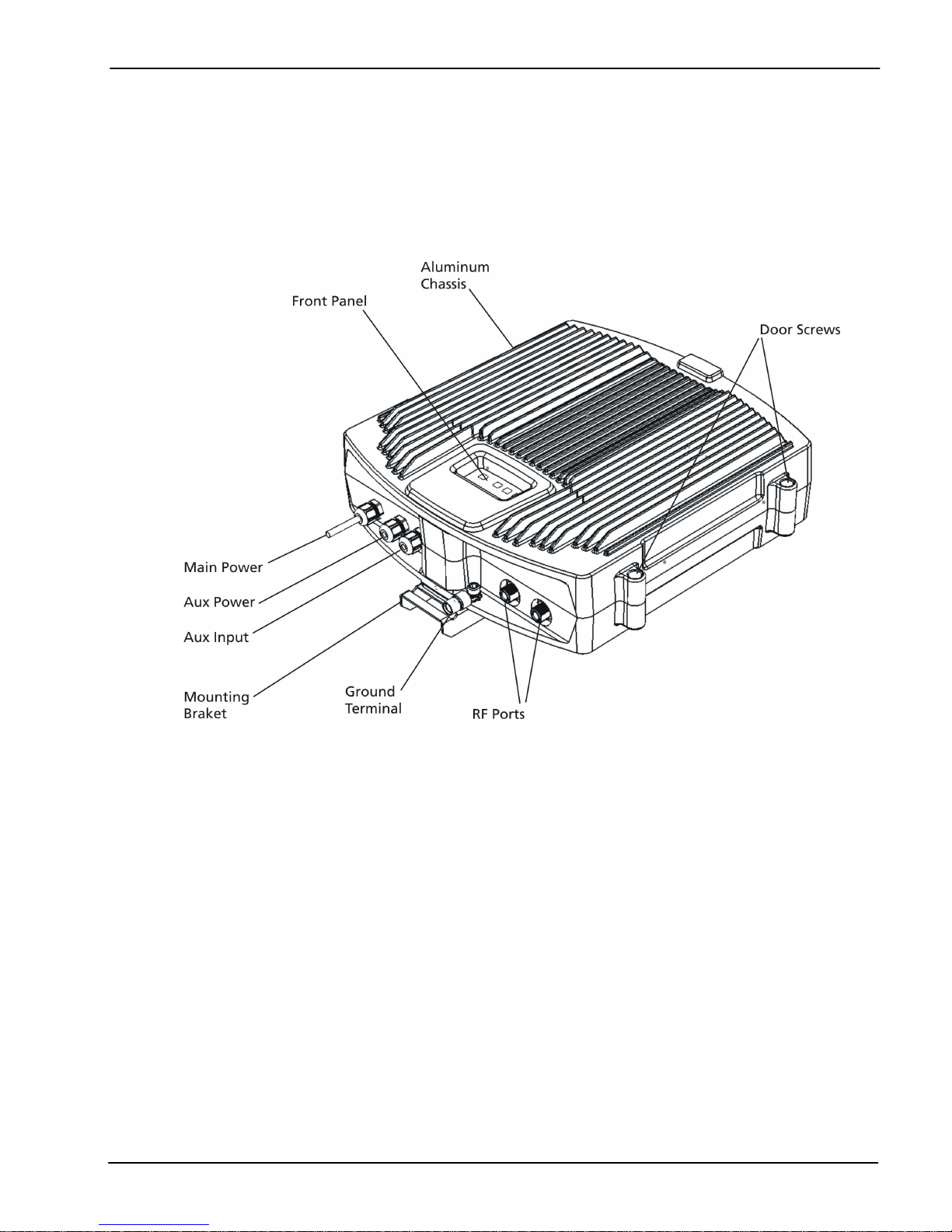
2. Product Description.
UM-0100-03.09 – August 2010 2
Page 8
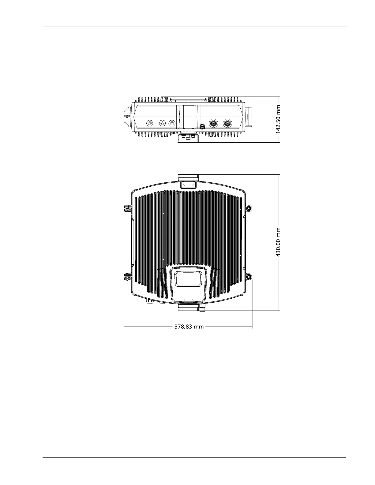
Dimensions
UM-0100-03.09 – August 2010 3
Page 9
3. Installation
Sitting the repeater
Fiplex repeaters are designed for outdoor usage. However, humidity and temperature changes may have
affect on the reliability. A preferable site for the repeater is thus indoor, in a tempered and ventilated room.
Repeaters are designed with a weather proof outdoor cabinet that can be mounted without any kind of
shelter from rain, snow or hail.
If a repeater is to be operated on the site when raining, snowing, or hailing there must be some kind of
permanent or temporary protection. This is applicable to gentle rainfall, snowfall or hail.
We extremely recommend not operating the repeater under very bad weather conditions, such as:
- Intense rainfall, snowfall or hail
- Storm or high wind
- Extremely low or high temperature
- High humidity of the air
Mounting
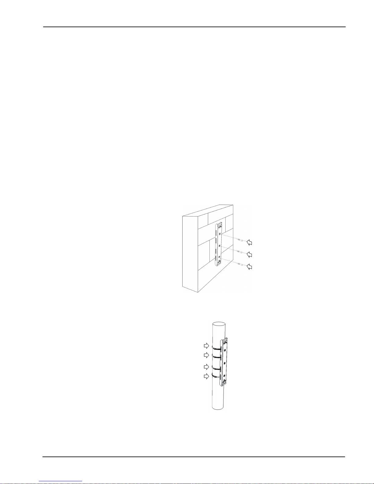
1. Mount the provided bracket
Normally, the repeater is mounted on a wall or pole. These mounting cases are shown below.
Figure 1
Figure 1 shows a bracket attachment to a wall using three fixing screws.
Figure 2
Figure 2 shows a bracket attachment to a pipe using two inox hose clamps (provided with bracket).
UM-0100-03.09 – August 2010 4
Page 10
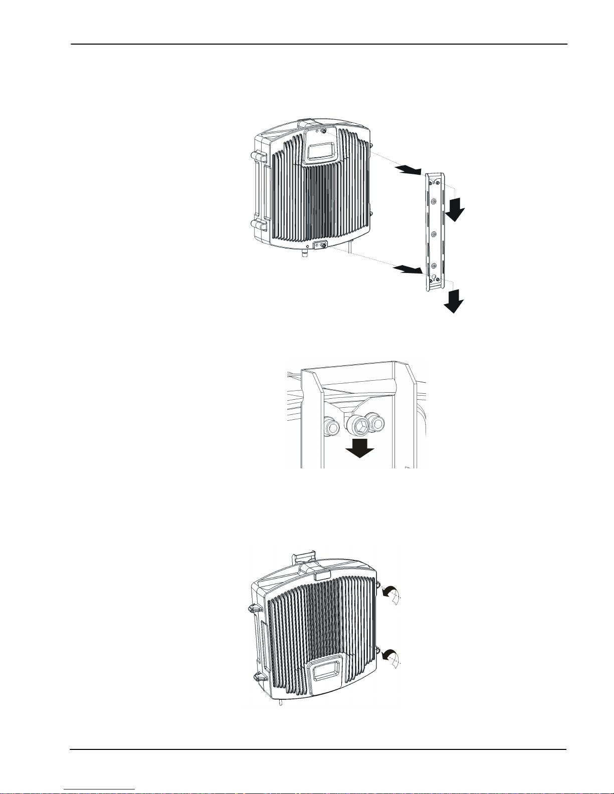
1. After attaching the bracket hang the repeater.
2. Screw the cabinet to the bracket
Attach repeater’s cabinet to the bracket using four M6 x 2” allen screws.
Figure 3
UM-0100-03.09 – August 2010 5
Release repeater cover
Page 11
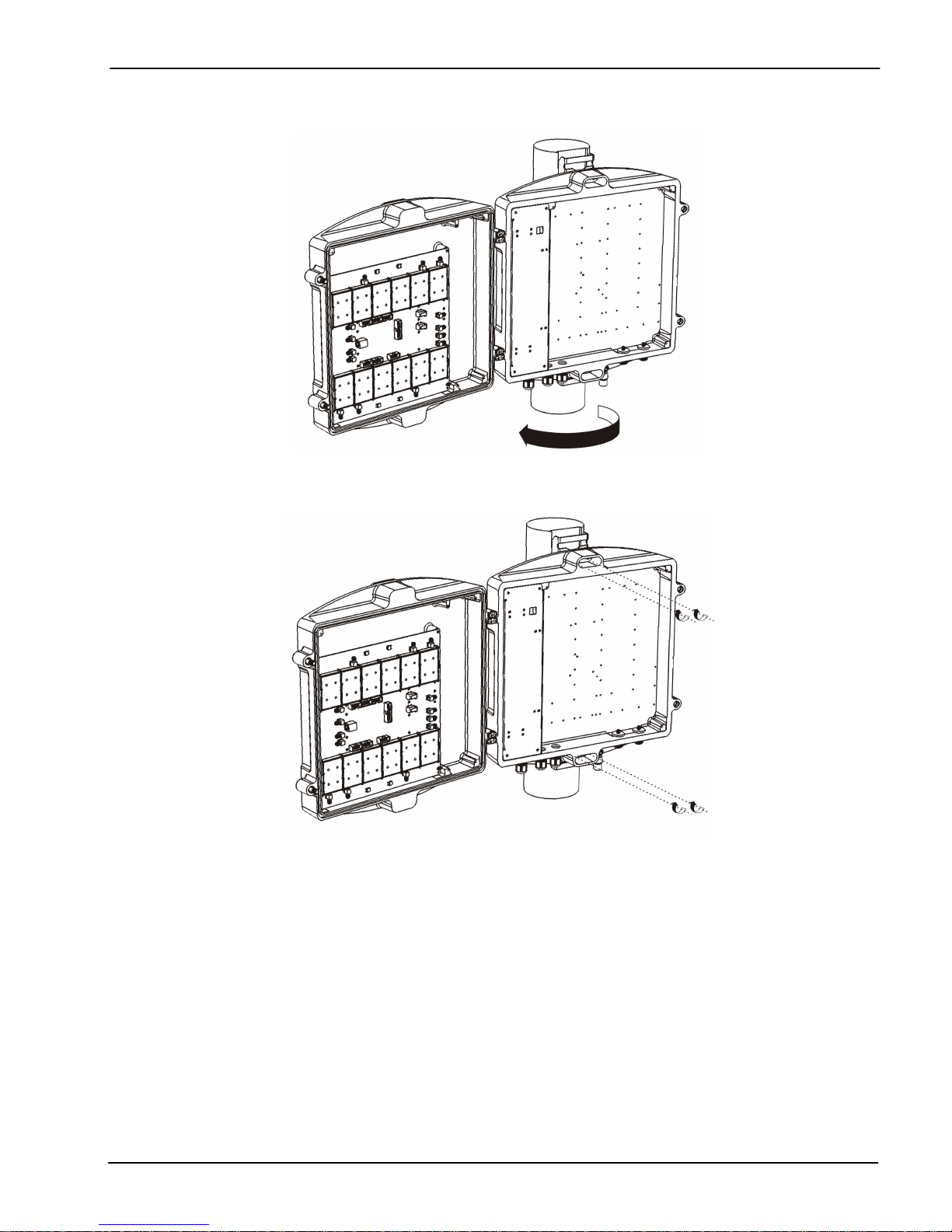
Open repeater cover
UM-0100-03.09 – August 2010 6
Place and screw the four M6 x 2” allen screws
Page 12
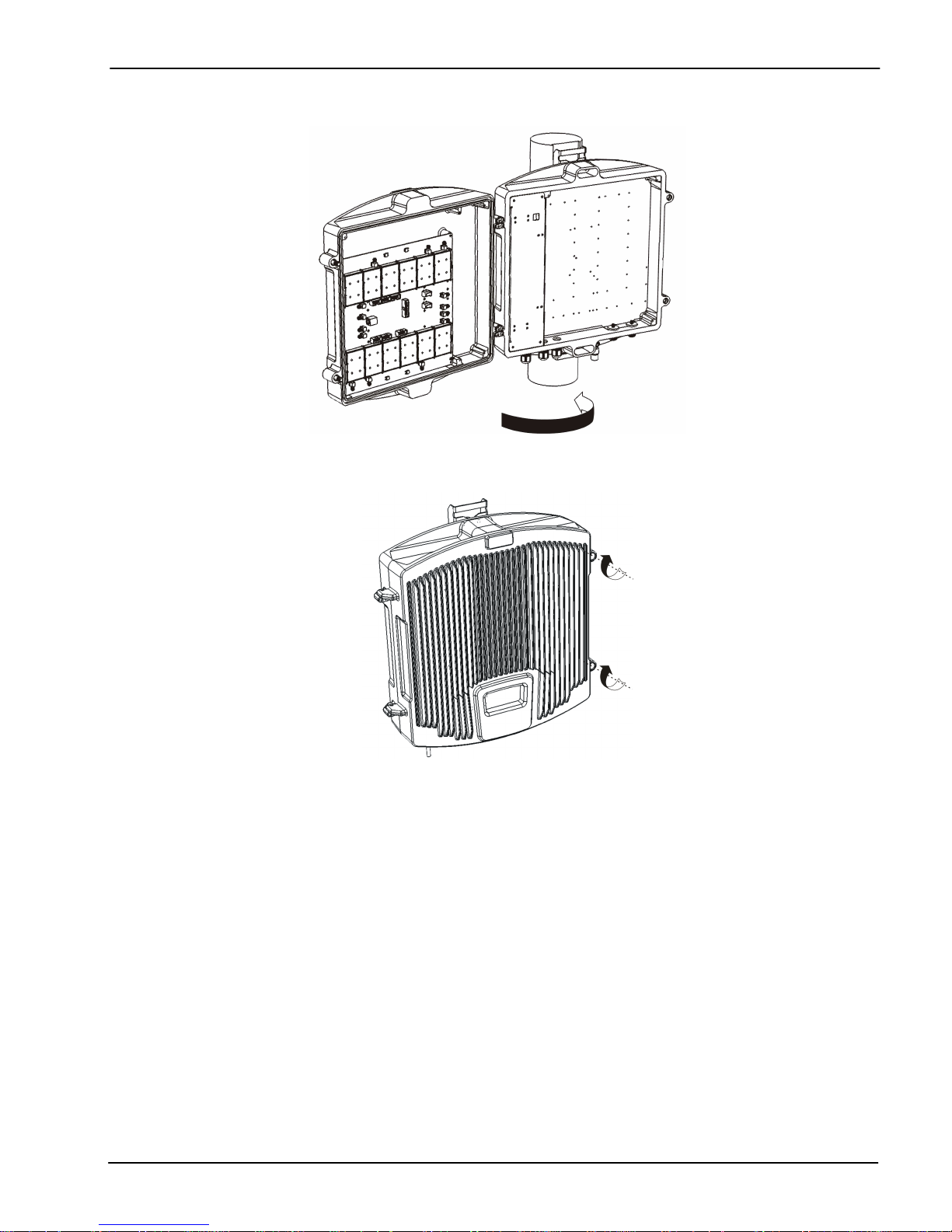
Close repeater cover
Secure repeater cover
UM-0100-03.09 – August 2010 7
Page 13
4. Commissioning
Connection
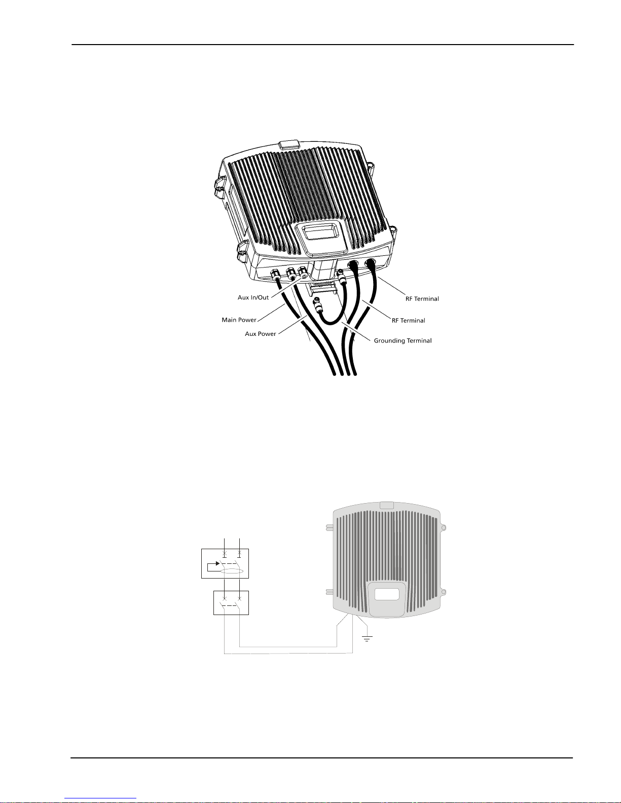
Figure 4
Figure 5 shows RF ports and AC and DC cable glands location.
1. Connect service antenna (“TO MOBILE” port) and donor antenna (“TO BASE” port) coaxial cables. N
type female connectors are used in the repeater.
2. Once RF ports of the repeater are properly loaded connect mains to the AC source.
Electrical installation must provide differential and termo-magnetic breaker elements according to electric
safety international regulations.
L N
DB
TMB
UM-0100-03.09 – August 2010 8
Page 14
3. Auxiliary DC connection can be provided to the repeater from an external DC source.
There is a dedicated cable gland for this purpose (EXT DC INPUT in figure 4), and a dedicated DC
connector labelled P60002 located at the main board. A 5.5mm x 2.1mm center positive plug must be used.
Please check appropriate DC voltage at repeater specification sheet.
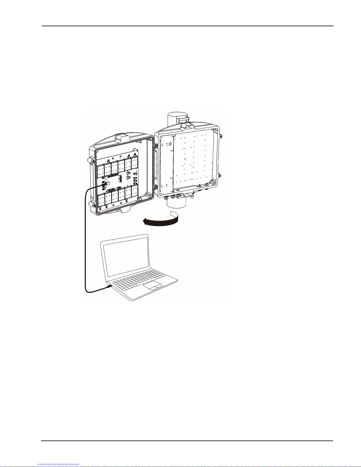
4. Once the repeater has been connected to power source (either AC mains or external DC), it takes about
20 seconds to run a booting routine. After that time repeater is ready to be connected via USB cable to a
computer running pFOMS in order to be properly configured.
See Part 2 Software of this manual to install pFOMS.
Starting operation
1. Setup desired filter configuration using pFOMS (only for programmable band selective and
programmable channel selective models).
For fixed bandwidth repeaters this feature will not allow user to make changes, so, skip this step for fixed
bandwidth models.
2. Setup desired operating gain using pFOMS. UL and DL chain are independent, so both values must be
set.
For nominal gain of the repeater these values must be set to zero.
UM-0100-03.09 – August 2010 9
Page 15
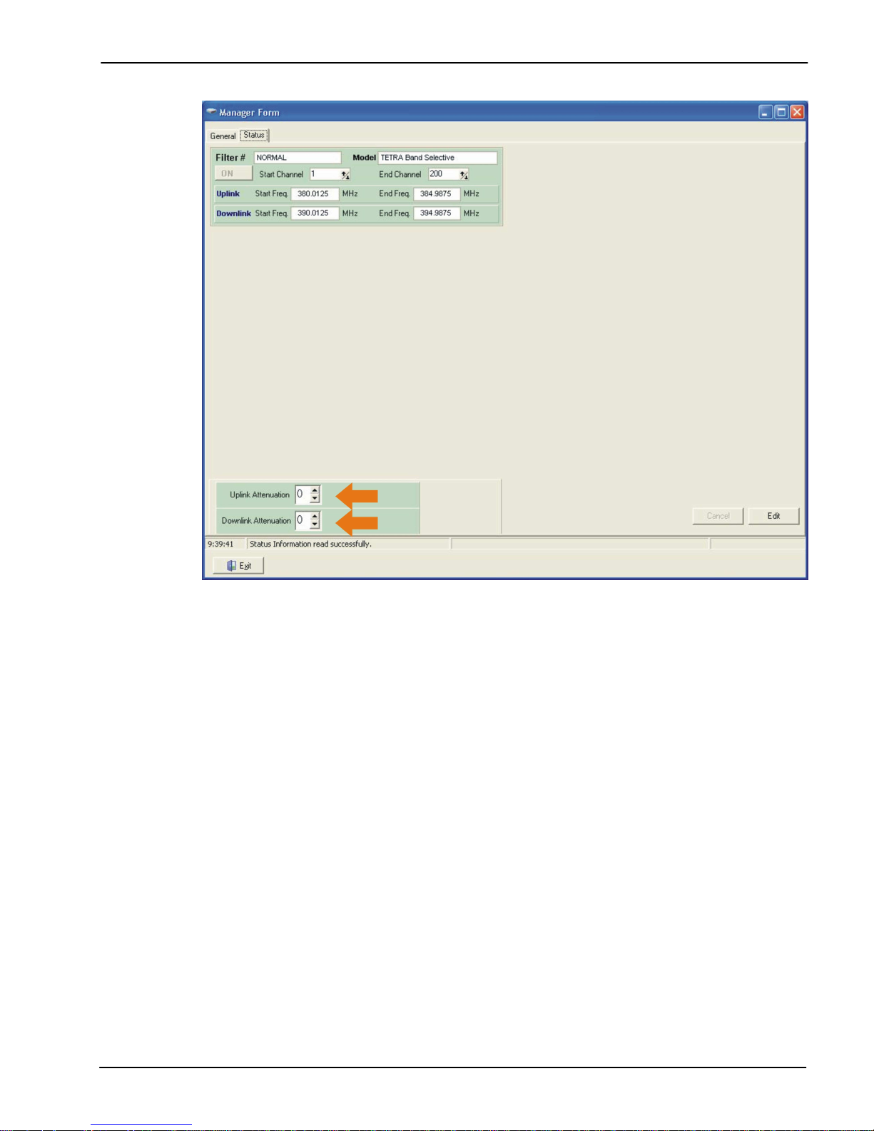
Figure 5
Figure 5 shows how to set up manual attenuation values.
UM-0100-03.09 – August 2010 10
Page 16
Status Indicators
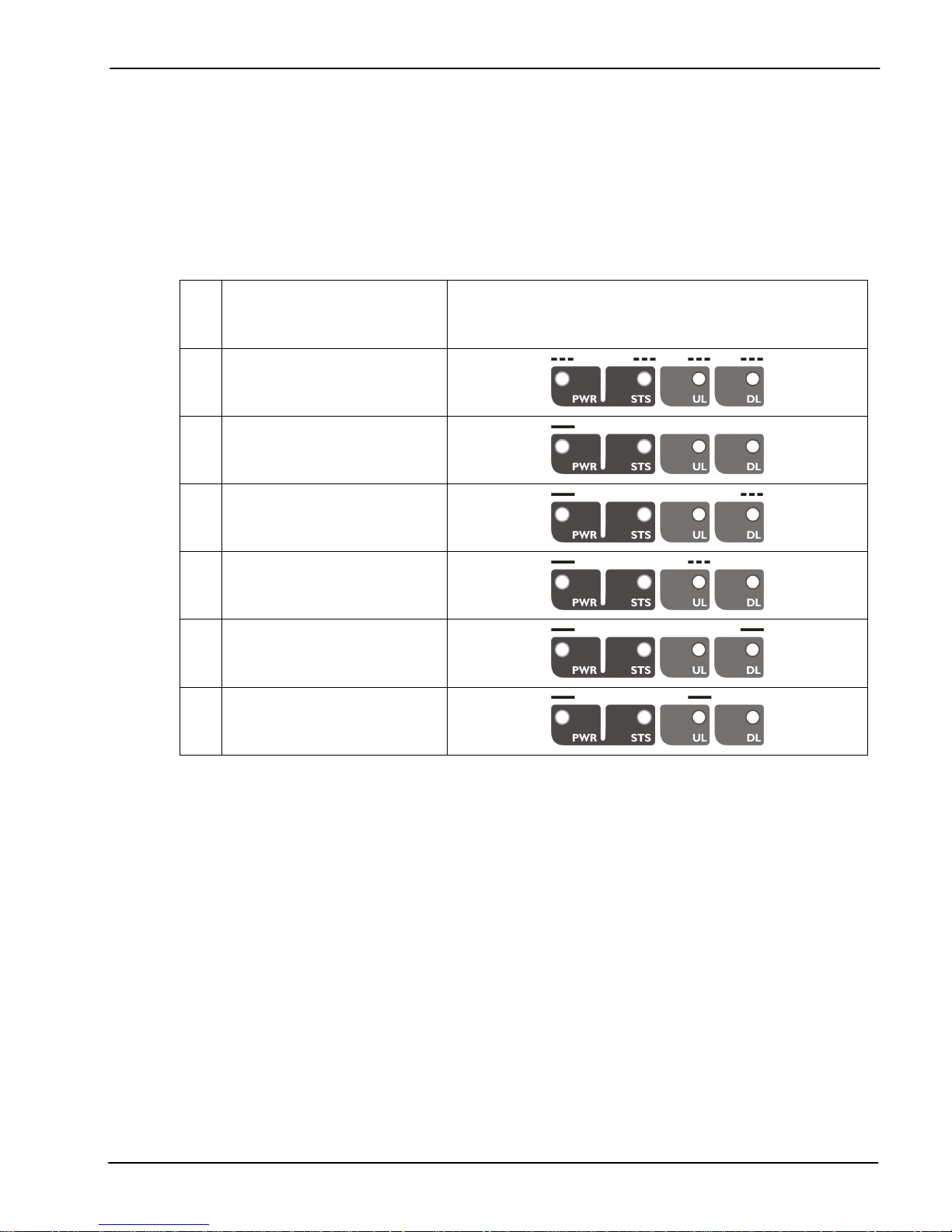
There is an indicator panel located at the front panel of the repeater. This led panel works as a status
monitor, in order to advice different operational conditions of the repeater.
There are four leds, first one the power ON indication led, labelled “PWR”.
A Second led, labelled “STS” resumes warnings regarding critical operational conditions of the repeater.
Third and fourth led resumes operational conditions for uplink “UL” and downlink “DL” chains.
Signalling will be explained in table 1.
Operative Condition Indicator Panel
1 Start UP
2 Stationary state
3 AGC DL
4 AGC UL
5 Overload DL
6 Overload UL
1. Start UP
Every time the repeater is plugged to AC mains (or auxiliary DC power), will start a self diagnosis and
booting sequence that lasts around 20 seconds, during this time repeater is not available for traffic, and the
reason is because an automatic antenna isolation control procedure runs in order to detect poor isolation
conditions. During this time all leds in the front panel will blink.
In case of bad isolation condition led “UL” or “DL” (depends on the path where auto-oscillation condition
was detected) will stay ON during five seconds.
2. Stationary state
Once the booting sequence is finished and under no AGC or Overload conditions only the PWR led must
keep ON.
3. AGC DL
Blinking condition indicates that AGC circuitry is active for downlink path. For further information
please read Automatic Gain Control (AGC) latter in this chapter.
Table 1
UM-0100-03.09 – August 2010 11
Page 17

4. AGC UL
Blinking condition indicates that AGC circuitry is active for uplink path. For further information
please read Automatic Gain Control (AGC) latter in this chapter.
5. Overload DL
Led permanently ON indicates that Overload protection circuitry for downlink path is active.
For further information please read Overload Protection latter in this chapter.
6. Overload UL
Led permanently ON indicates that Overload protection circuitry for uplink path is active.
For further information please read Overload Protection latter in this chapter.
Automatic Gain Control (AGC)
Automatic Gain Control circuitry is intended to keep repeater’s output power at a fixed level when input
signals exceed maximum values, avoiding quality signal degradation by intermodulation generation.
When AGC is active AGC leds from UL or DL (or both) will blink, this means that signal level from donor
site (or from service area) plus repeater gain produces an output power that is above the maximum
composite output power of the repeater. This should not be considered an undesired working condition, far
from that; this is the best operating condition because you are getting the maximum composite output
power available from the repeater.
Anyway is a good practice to increase attenuation (reducing gain), until AGC led turns off, this operation
releases AGC circuitry dynamic range.
Also is a good practice to check signals from donor site to ensure that undesired signals are not being
amplified by the repeater, or even desired signal levels are not excessively high taking repeater to an
overload condition.
Overload Protection
When AGC circuit reaches its limit, the power amplifier stage is shut down to prevent harmful distortion and
potential damage to the repeater. After approximately ten seconds the system checks if overload condition
is still present, if this happens amplifiers will remain off. This cyclic check will continue until condition that
makes AGC circuitry reach its limits disappears.
Conditions that can cause AGC to reach its limits include the presence of one or more very strong
channels, a strong in-band noise source, or amplifier oscillation due to poor antenna isolation.
When overload protection lower row led from UL or DL (or both) will be ON permanently.
Laboratory Measurements
For specific parameters verification and laboratory tests, please contact factory.
Detailed procedures, recommended tests set up, and a knowledge engineering team will bring adequate
support to perform this measurements in a comfortable and safely way
.
UM-0100-03.09 – August 2010 12
Page 18
Part 2 SOFTWARE
5. Installation
The following section will describe the steps to be followed in order to install and use the pFOMS software
with your Fiplex repeater.
1. Execute the Fiplex Portable Foms installer and choose the default path “C:\program files\fiplex”.
Please do not change this location.
2. Turn on the Repeater
BE SURE THAT “TO MOBILE” AND “TO BASE” PORTS ARE PROPERLY LOADED
BE SURE THAT “TO MOBILE” AND “TO BASE” PORTS ARE PROPERLY LOADED
BE SURE THAT “TO MOBILE” AND “TO BASE” PORTS ARE PROPERLY LOADEDBE SURE THAT “TO MOBILE” AND “TO BASE” PORTS ARE PROPERLY LOADED
EITHER WITH 50 OHMS DUMMY LOADS
EITHER WITH 50 OHMS DUMMY LOADS OR RADIATING SYSTEM.
EITHER WITH 50 OHMS DUMMY LOADSEITHER WITH 50 OHMS DUMMY LOADS
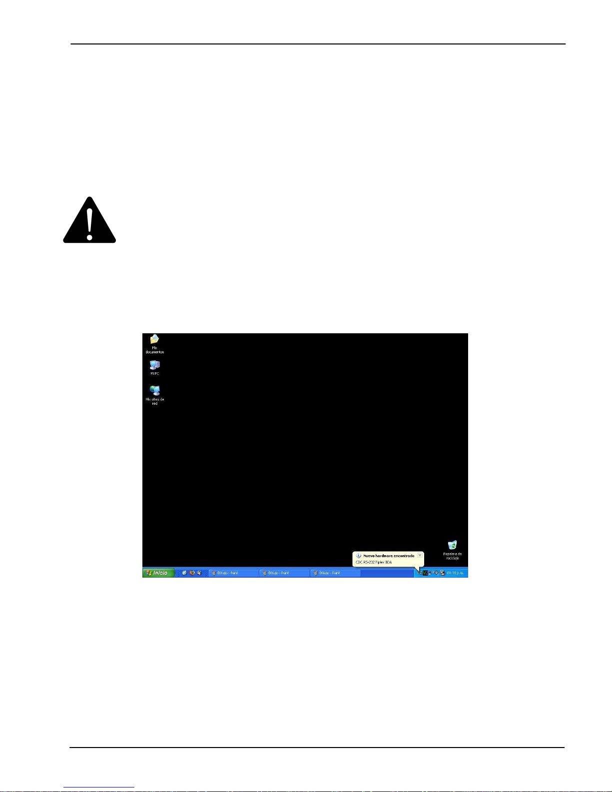
3. Plug in USB cable to P50000 USB B male type connector. Repeater HW will trigger the installation of its
driver, which is a COM port emulator.
“New hardware found” advice should be noticed.
OR RADIATING SYSTEM.
OR RADIATING SYSTEM. OR RADIATING SYSTEM.
UM-0100-03.09 – August 2010 13
Page 19
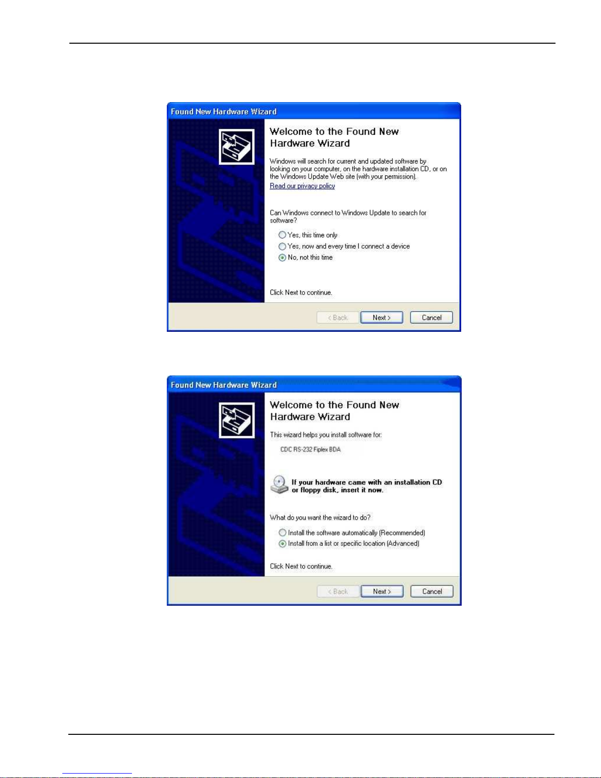
4. Windows will start its hardware installation assistant, follow the steps and indicate the driver location.
Select “No, not this time”
Select “Install from a list or specific location (Advanced)
UM-0100-03.09 – August 2010 14
Page 20
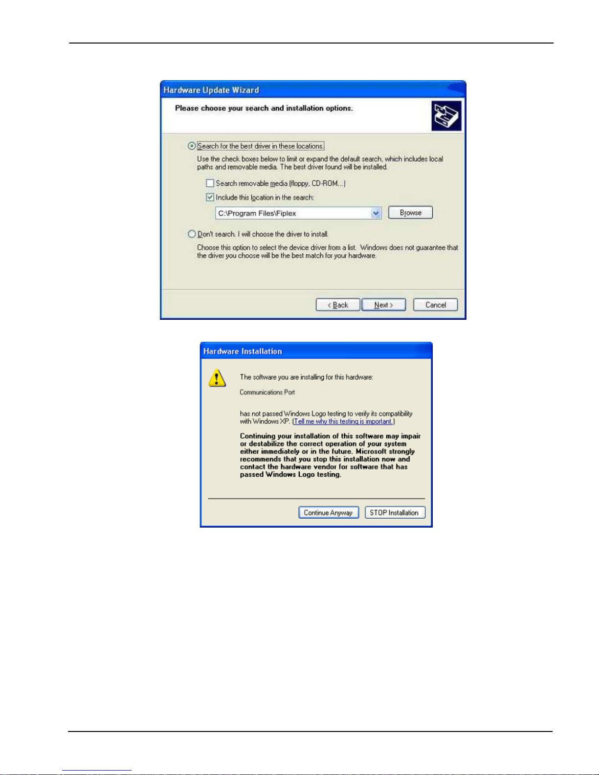
Windows probably complains because this is not an official Microsoft Windows driver, click in “Continue
Anyway”
UM-0100-03.09 – August 2010 15
Page 21
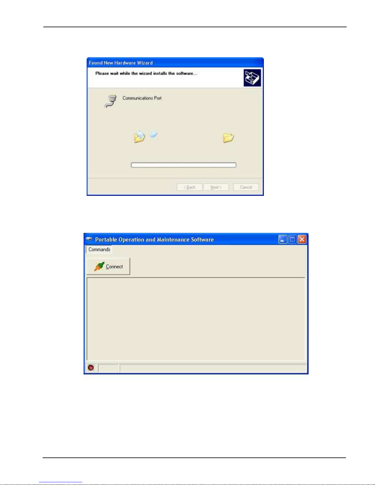
5. After having installed the CDC-RS232 Fiplex driver, run pFOMS Software.
UM-0100-03.09 – August 2010 16
Click “Connect”.
Page 22
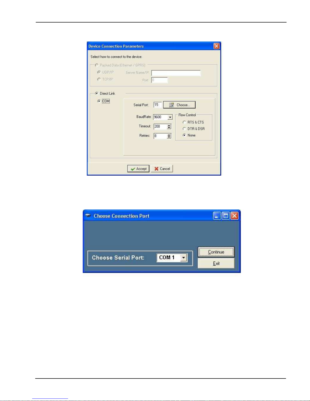
Click “Choose”
Select The Serial Com port that just appeared on your PC. Remember that the BDA driver installs itself as
a generic Com Port so if properly installed, you should have a new comport not present before connecting
the Repeater.
Click “Continue”.
UM-0100-03.09 – August 2010 17
Page 23
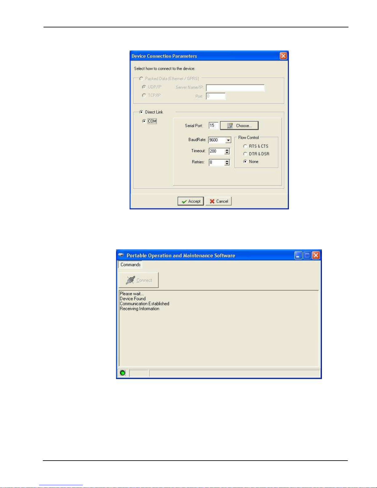
Choose Flow Control “None”.
Click “Accept”.
This window will be active while Repeater is establishing connection with pFOMS.
UM-0100-03.09 – August 2010 18
Page 24
6. Overview
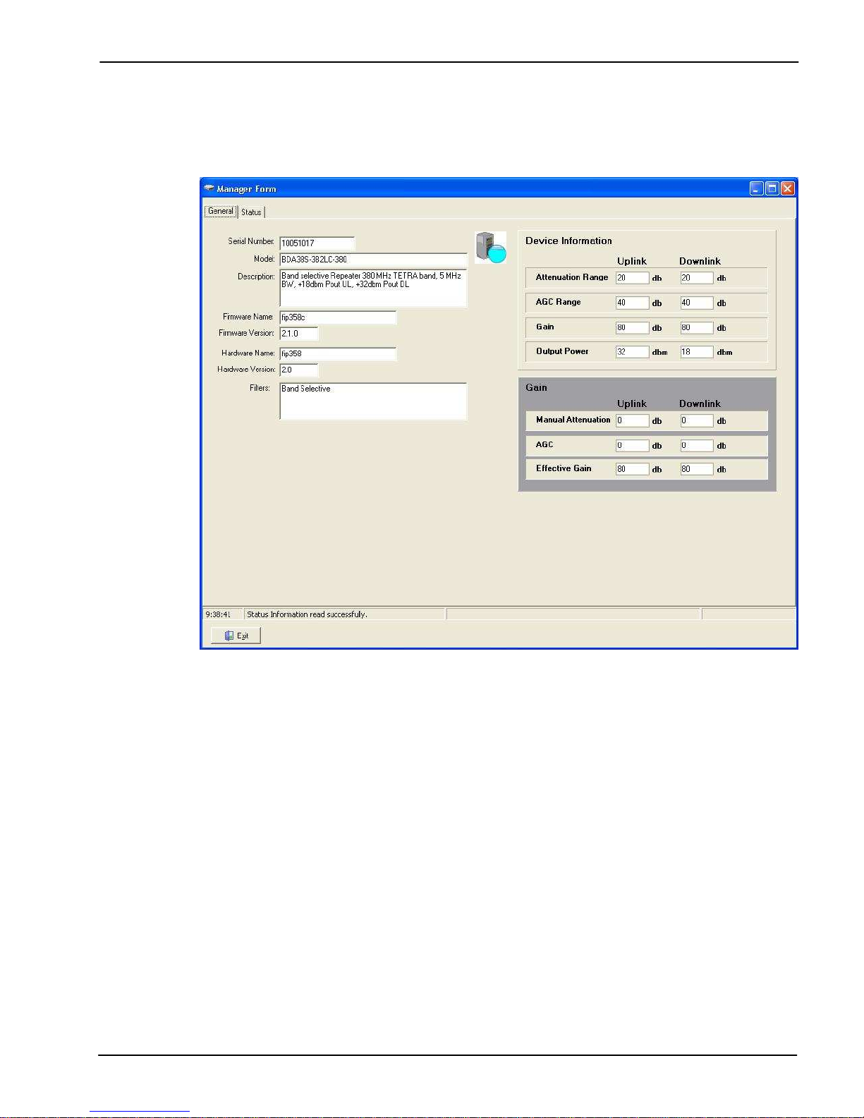
General Tabsheet
This tabsheet displays general information from repeater.
First eight fields shown at the upper left corner of the window displays identity information of the repeater,
this information is stored at repeater’s firmware.
Device Information: four fields at the upper right of the window displays static nominal values of the
repeater, this information are shown by pFOMS after detecting repeater model.
Gain: these fields allow user to know actual manual attenuation, AGC, and effective gain of repeater, this is
dynamic information, constantly and automatically being updated by pFOMS.
UM-0100-03.09 – August 2010 19
Page 25
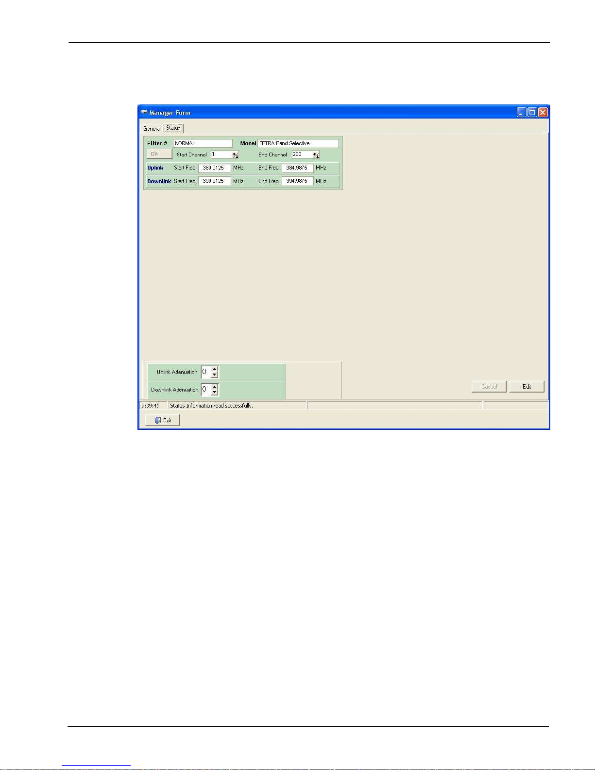
Status tabsheet
This tabsheet shows configurable parameters of the repeater:
Filters: active filters will appear in green, not installed filters in gray and filters with communication errors
will be purple.
Band selective programmable filters shows Start / Stop channel and Start / Stop frequency.
Channel selective programmable filters will only show Start channel, in this case the meaning for start
channel is filter center BW channel.
Band selective fixed filters will show start frequency or channel and the meaning is center BW frequency or
channel.
Manual attenuation: shows the status of uplink and downlink attenuation.
UM-0100-03.09 – August 2010 20
Page 26
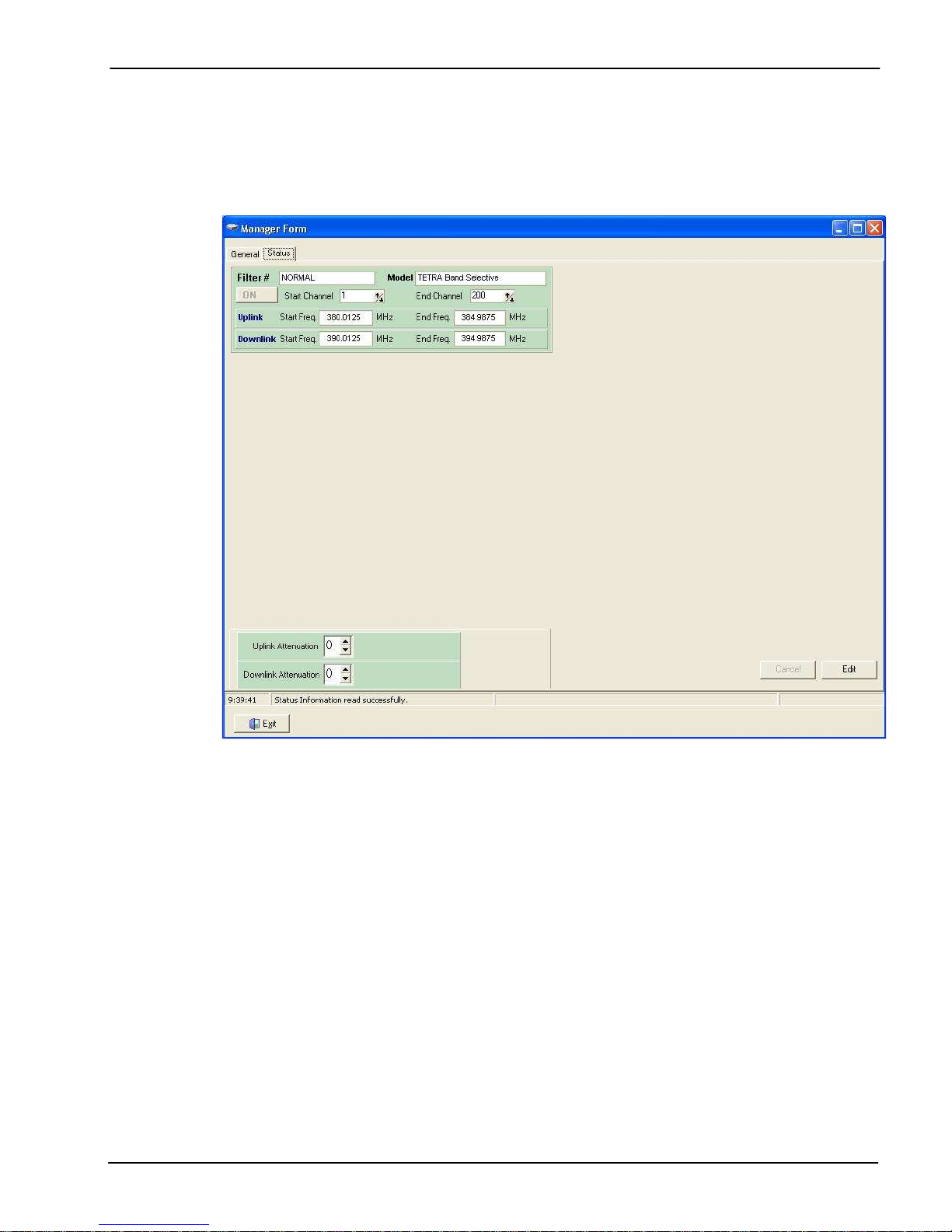
Configuration
In order to setup operative parameters of the repeater such as manual attenuation UL and/or DL and filters,
user must click “Edit” at the bottom right corner of Status tabsheet.
Now user is free to change configurable values.
Once configured operational parameters click “Accept”, after a few seconds changes will be displayed
(once pFOMS refresh the window), with updated information.
UM-0100-03.09 – August 2010 21
 Loading...