


FIORI GROUP S.p.A.
Via per Ferrara, 7
41034 FINALE EMILIA (Modena Italia)
Tel. +39.0535.92357 - Fax +39.0535.90960
http://www.fi origroup.com
uk_EN
TRANSLATION FROM
ORIGINAL LANGUAGE
USE AND MAINTENANCE MANUAL
RIF. 9304444428 ed. 03
id.:
FIORI BATCH CONTROLLER
REV. 01 24/03/2015


3
REV. 00 02/01/2015
id.:
CONTENTS
1 WARNINGS ..................................................................................................................................................7
2 SYSTEM DESCRIPTION .............................................................................................................................9
2.1 SETTING UP ..........................................................................................................................................9
2.2 COMPONENTS ....................................................................................................................................10
2.3 KEY FUNCTIONS .................................................................................................................................11
2.4 PRINTER FUNCTIONS AND PAPER ROLL REPLACEMENT ............................................................ 12
2.5 TECHNICAL FEATURES .....................................................................................................................13
3 FBC MODE FUNCTIONS ..........................................................................................................................15
3.1 TURN ON .............................................................................................................................................15
3.2 ACCESSING THE FUNCTIONS ...........................................................................................................15
3.3 MAIN PAGE DESCRIPTION ................................................................................................................15
3.4 ADJUSTING THE DISPLAY BRIGHTNESS .........................................................................................15
3.5 TURNING OFF THE SYSTEM .............................................................................................................15
3.6 WATER MANAGEMENT ......................................................................................................................16
3.7 AUTOMATIC WATER LOADING .........................................................................................................16
3.8 MANUALLY LOADING A COMPONENT .............................................................................................16
3.9 LOADING COMPONENTS THROUGH WEIGHING ............................................................................17
3.10 LOADING PROGRESS INDICATORS .................................................................................................17
3.11 CANCELLING LAST WEIGHING .........................................................................................................17
3.12 TIP-OFF (DYNAMIC WEIGHING) ........................................................................................................18
3.13 BAG-COUNTING FUNCTION ............................................................................................................... 19
3.14 RESETTING MEASURED WEIGHTS ..................................................................................................19
3.15 COMPLETING WATER LOADING .......................................................................................................20
3.16 PRINT MENU .......................................................................................................................................20
3.17 HELP PAGE .........................................................................................................................................21
3.18 ALARMS PAGE ....................................................................................................................................21
3.19 CALIBRATING THE TARE ...................................................................................................................22
3.20 ADDITIONAL FUNCTIONS ..................................................................................................................24
3 CBV STANDARD MODE FUNCTIONS .....................................................................................................25
3.1 TURN ON .............................................................................................................................................25
3.2 ACCESSING THE FUNCTIONS .......................................................................................................... 25
3.3 MAIN PAGE DESCRIPTION ................................................................................................................25
3.4 ADJUSTING THE DISPLAY BRIGHTNESS .........................................................................................25
3.5 TURNING OFF THE SYSTEM ............................................................................................................25
3.6 SELECTING A RECIPE ........................................................................................................................26
3.7 MOISTURE OF AGGREGATES ...........................................................................................................26
3.8 SELECTING THE VOLUME .................................................................................................................27
3.9 AUTOMATIC WATER LOADING .........................................................................................................27
3.10 LOADING COMPONENTS THROUGH WEIGHING ............................................................................28
3.11 MANUALLY LOADING A COMPONENT .............................................................................................28
3.12 LOADING PROGRESS INDICATORS .................................................................................................29
3.13 CANCELLING LAST WEIGHING .........................................................................................................29
3.14 TIP-OFF (DYNAMIC WEIGHING) ........................................................................................................29
3.15 AUTOMATICALLY LOADING THE ADDITIVE .....................................................................................30
3.16 WATER LOADING ................................................................................................................................31
3.17 BAG-COUNTING FUNCTION ............................................................................................................... 32

4
REV. 00 02/01/2015
id.:
CONTENTS
3.18 VIEWING THE MIXING STATUS .........................................................................................................32
3.19 POURING THE MIX .............................................................................................................................33
3.20 RESETTING THE VALUES OF THE WEIGHTS MEASURED ............................................................33
3.21 PRINT MENU .......................................................................................................................................34
3.22 HELP PAGE .........................................................................................................................................36
3.23 ALARMS PAGE ....................................................................................................................................36
3.24 CALIBRATING THE TARE ....................................................................................................................36
3.25 WATER MANAGEMENT ......................................................................................................................38
3.26 FUNCTION MENU ................................................................................................................................38
3 CBV ADVANCED MODE FUNCTIONS .....................................................................................................41
3.1 TURN ON .............................................................................................................................................41
3.2 ACCESSING THE FUNCTIONS .......................................................................................................... 41
3.3 MAIN PAGE DESCRIPTION ................................................................................................................41
3.4 ADJUSTING THE DISPLAY BRIGHTNESS .........................................................................................41
3.5 TURNING OFF THE SYSTEM ............................................................................................................41
3.6 SELECTING A RECIPE ........................................................................................................................42
3.7 MOISTURE OF AGGREGATES ...........................................................................................................42
3.7.1 Manually enter the humidity percentage ................................................................................................42
3.7.2 Use of the Mikrolab ............................................................................................................................... 43
3.7.3 Use of the moisture probe .....................................................................................................................44
3.8 SELECTING THE VOLUME .................................................................................................................44
3.9 AUTOMATIC WATER LOADING .........................................................................................................44
3.10 LOADING COMPONENTS THROUGH WEIGHING ............................................................................45
3.11 MANUALLY LOADING A COMPONENT .............................................................................................45
3.12 LOADING PROGRESS INDICATORS .................................................................................................46
3.13 CANCELLING LAST WEIGHING .........................................................................................................46
3.14 TIP-OFF (DYNAMIC WEIGHING) ........................................................................................................46
3.15 AUTOMATICALLY LOADING THE ADDITIVE .....................................................................................47
3.16 WATER LOADING ................................................................................................................................48
3.17 BAG-COUNTING FUNCTION ............................................................................................................... 48
3.18 VIEWING THE MIXING STATUS .........................................................................................................49
3.19 POURING THE MIX .............................................................................................................................49
3.20 RESETTING THE VALUES OF THE WEIGHTS MEASURED ............................................................50
3.21 PRINT MENU .......................................................................................................................................50
3.22 HELP PAGE .........................................................................................................................................52
3.23 ALARMS PAGE ....................................................................................................................................52
3.24 CALIBRATING THE TARE ....................................................................................................................52
3.25 WATER MANAGEMENT ......................................................................................................................54
3.26 FUNCTION MENU ................................................................................................................................55
3.27 DATA SENT TO GPS AND GPRS SYSTEMS .....................................................................................56
4 FBC MODE FUNCTIONS FOR THE FOREMAN ONLY ............................................................................57
4.1 MENU SETTINGS ................................................................................................................................57
4.2 MENU FOREMAN ................................................................................................................................57
4.3 COMPONENTS AND RECIPES ...........................................................................................................58
4.4 SYSTEM CONFIGURATION ................................................................................................................59
4.5 DIAGNOSTICS .....................................................................................................................................59
4.6 SYSTEM DIAGNOSTICS .....................................................................................................................59
4.7 PASSWORD CHANGE ........................................................................................................................59

5
REV. 00 02/01/2015
id.:
CONTENTS
4.8 SETTING THE CLOCK .........................................................................................................................60
4.9 PRINTING THE PARAMETERS ...........................................................................................................60
4 CBV STANDARD MODE FUNCTIONS FOR THE FOREMAN ONLY ......................................................61
4.1 MENU SETTINGS ................................................................................................................................61
4.2 MENU FOREMAN ................................................................................................................................61
4.3 COMPONENTS AND RECIPES ...........................................................................................................62
4.3.1 Entering the components .......................................................................................................................62
4.3.2 Creating mixes .......................................................................................................................................63
4.3.3 Downloading components and recipes ..................................................................................................64
4.3.4 Uploading components and recipes ......................................................................................................64
4.4 SYSTEM CONFIGURATION ................................................................................................................65
4.5 MACHINE DIAGNOSTICS ...................................................................................................................65
4.6 SYSTEM DIAGNOSTICS .....................................................................................................................65
4.7 PASSWORD CHANGE ........................................................................................................................65
4.7 SETTING THE CLOCK .........................................................................................................................66
4.8 PRINTING THE PARAMETERS ...........................................................................................................66
4 CBV ADVANCED MODE FUNCTIONS FOR THE FOREMAN ONLY ......................................................67
4.1 MENU SETTINGS ................................................................................................................................67
4.2 MENU FOREMAN ................................................................................................................................67
4.3 COMPONENTS AND RECIPES ...........................................................................................................68
4.3.1 Entering the components .......................................................................................................................68
4.3.2 Creating mixes .......................................................................................................................................69
4.3.3 Downloading components and recipes ..................................................................................................70
4.3.4 Uploading components and recipes ......................................................................................................70
4.4 SYSTEM CONFIGURATION ................................................................................................................71
4.5 MACHINE DIAGNOSTICS ...................................................................................................................71
4.6 SYSTEM DIAGNOSTICS .....................................................................................................................71
4.7 PASSWORD CHANGE ........................................................................................................................71
4.8 SETTING THE CLOCK .........................................................................................................................72
4.9 PRINTING THE PARAMETERS ...........................................................................................................72
5 ALARM LIST ..............................................................................................................................................73
5.1 OPERATING ALARMS .........................................................................................................................73
5.2 SYSTEM DIAGNOSTICS ALARMS .....................................................................................................73
5.2 ALARM TABLE .....................................................................................................................................74
6
6 CBV STANDARD ADDITIVE FEEDER
.....................................................................................................
.....................................................................................................7777
6.1
6.1 TECHNICAL DATA
...............................................................................................................................
...............................................................................................................................7777
6.2
6.2 REFERENCES AND DESCRIPTIONS OF THE MAIN DEVICES
.......................................................
.......................................................7777
6.3
6.3 FILLING THE ADDITIVE T ANKS
..........................................................................................................
..........................................................................................................7878
6.4
6.4 SCHEDULED MAINTENANCE TABLE
................................................................................................
................................................................................................7878
6.5
6.5 CHECKING AND MAINTAINING
..........................................................................................................
..........................................................................................................7979
7
7 CBV ADVANCED DOUBLE ADDITIVE FEEDER
.....................................................................................
.....................................................................................8181
7.1
7.1 TECHNICAL DATA
...............................................................................................................................
...............................................................................................................................8181
7.2
7.2 REFERENCES AND DESCRIPTIONS OF THE MAIN DEVICES
.......................................................
.......................................................8181
7.3
7.3 FILLING THE ADDITIVE T ANKS
..........................................................................................................
..........................................................................................................8282
7.4
7.4 SCHEDULED MAINTENANCE TABLE
................................................................................................
................................................................................................8282
7.5
7.5 CHECKING AND MAINTAINING
..........................................................................................................
..........................................................................................................8383
REV. 01 24/03/2015


7
REV. 00 02/01/2015
id.:
WARNINGS
1
- Carefully read this manual for proper use of the system.
- Before cleaning the system, turn off the vehicle.
- Use only a clean moist cloth to clean the system. Do not use liquid products or aerosols.
- Do not spray water directly or indirectly onto the device with a hose or use pails of water or similar.
- Do not let the system come into direct contact with:
- Ammonia
- Acetone
- Benzene
- Hydrocarbons
- Perchlorethylene
- Trichlorethylene
- Methanol
- Dishwasher detergents
- Washing machine detergents
- Dichloromethane
- Ethyl ether
- Toluene
- Do not insert any objects in the system or the printer casing as they may damage some parts vital for proper
functioning.
- Do not operate on the system in any way except for the maintenance operations described in this manual.
- For any problem not indicated in this manual contact the supplier.


9
REV. 00 02/01/2015
id.:
SYSTEM DESCRIPTION
2
2.1 SETTING UP
The system is made up of one of the following modes; each version calls for a specifi c confi guration which is
described in the diagram in which we include all the available options.
A sensor kit is provided for each mode.
FBC Weighing
Component Archive Management
Setting up preset values
Print receipt
Water pump automatic management
Standard USB port (for software upgrade only)
CBV STANDARD Component Archive Management
Setting up preset values
Advanced weighing with angle compensation (proximity),
Recipe Archive Management and components ratio recalculation
Water compensation in hygroscopic components
Advanced USB port for upgrading the software, downloading receipts, and uploading/
downloading components and recipes.
Automatic management of the water pump and additive pump
Mixing quality control
CBV ADVANCED Component Archive Management
Setting up preset values
Recipe Archive Management and components ratio recalculation
Advanced weighing with angle compensation (tilt sensor),
Machine tilting safety check
Water compensation in hygroscopic components
Advanced USB port for upgrading the software, downloading receipts, and uploading/
downloading components and recipes.
Automatic management of the water pump and additive pump
Mixing quality control
Moisture Probe and Mikrolab management
Data transmission management towards a GSM/GPRS communication device
The system has been designed to operate on a concrete production vehicle.
It allows to set up different mix and visualize and record the quantity of components (cement, water, gravel,
sand, etc.) used
After storing the components and the recipes, the electronic system allows monitoring the correct quantity of
each component of each recipe during loading.
The recipe complete with a list and weight of the components can be printed using the printer unit FPR282
(optional) and stored in electronic format on a pendrive so that you have a record of the operations performed
and can keep track of the compositions made.
10
REV. 00 02/01/2015
id.:
SYSTEM DESCRIPTION
2
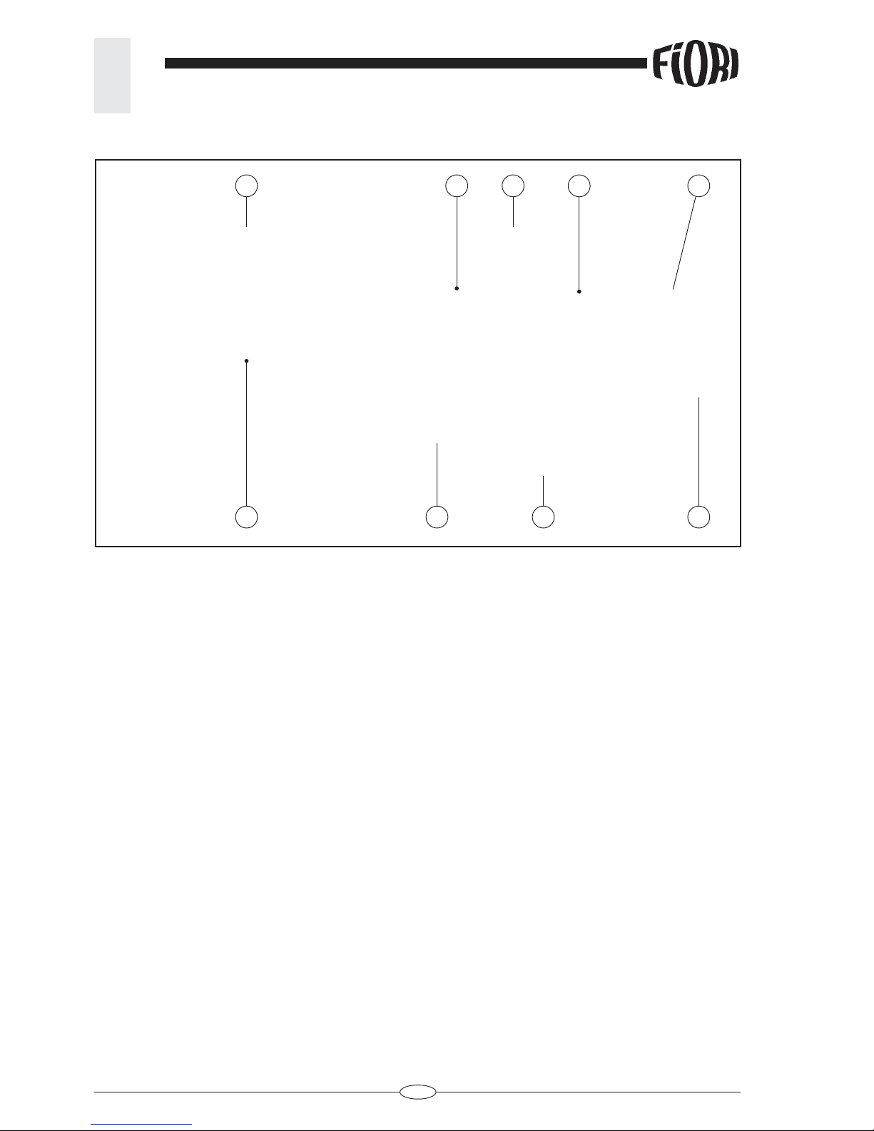
2.2 COMPONENTS
1 - Operating panel
2 - Display
3 - Keypad
4 - Printer connector
5 - System wiring connector
6 - USB
7 - Buzzer
8 - Printer
9 - Thermal paper roll
3 412
567
8
9

11
REV. 00 02/01/2015
id.:
SYSTEM DESCRIPTION
2
2.3 KEY FUNCTIONS
Key Function when weighing Function when editing
Print receipt Alphanumeric input
Access the mixing page Alphanumeric input
Start and stop (hold down for 3 secs.) Alphanumeric input
Alphanumeric input
Alphanumeric input
Access the “short manual” (hold down for 3 secs.) Alphanumeric input
Accessing the bag-counting function Alphanumeric input
Alphanumeric input
Access the diagnostics page
Activates the “reset weight” function (hold down for 3 secs.)
Activates the “boom calibration” function (hold down for 3 secs.) Alphanumeric input
Access the FUNCTIONS menu Alphanumeric input
Exit editing
Cancel the last weighing
Access the water management menu
Activates the tip-off mode Alphanumeric input
Activates the component manual loading selection Alphanumeric input
Confi rms selection
Navigation keys Navigation
Adjusts screen brightness Navigation
12
REV. 00 02/01/2015
id.:
SYSTEM DESCRIPTION
2
3
4
1
2
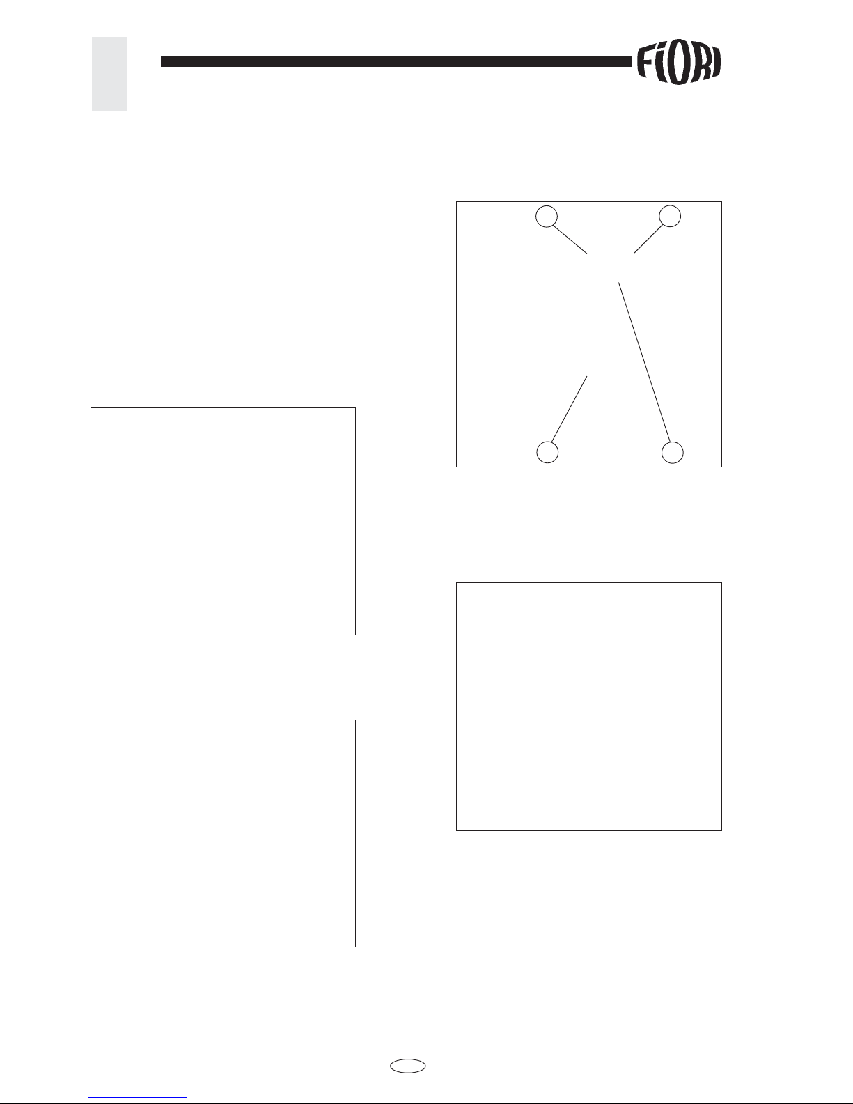
2.4 PRINTER FUNCTIONS AND PAPER ROLL REPLACEMENT
The printer is used to print the the record (of each single load).
1 Button to open the cover to replace the paper roll and a
status LED:
a - When it is on fi xed it means that there is no error.
b -
When it fl ashes slowly it means that the paper has run out.
c - When it fl ashes fast it means that there is an error
(head overheating or power supply fault).
2 FEED button (paper feed).
3 Paper outfeed.
4 Paper roll.
To replace the paper roll:
Press the key “1” to open the cover.
Remove the used paper roll and insert the new one (paper
width 57 mm)
Closing the cover insert the border of the paper roll in the
suitable opening “3”

13
REV. 00 02/01/2015
id.:
SYSTEM DESCRIPTION
2
2.4 TECHNICAL FEATURES
Control unit dimensions 160 x 120 x 80 mm
Printer dimensions 120 x 120 x 80 mm
Supply voltage 10 ÷ 35 Vdc
Allowed ambient temperature during the operating phase -20°C) / +60°C
Allowed ambient temperature during the non-operating phase -30°C) / +80°C
Maximum front tilting (Y axis) of the machine during weighing (**) ± 10°
Paper type for printer Thermal
Maximum number of recipes (*) 16
Maximum number of components for each recipe 8
Maximum number of components available in the data storage 32
Languages 9
Selectable unit of measurement kg / lb
Water compensation in the components (*)
Compensation of the machine’s front tilting (Y axis)
during the weighing phase (*) within the ± 10° range
(*) not available in FBC mode
(**) ± 2.5° in FBC mode


15
REV. 00 02/01/2015
id.:
FBC
MODE FUNCTIONS
3
3.1 TURN ON
Press and hold the key until the start page is displayed.
The start page is displayed for a few seconds,
3.2 ACCESSING THE FUNCTIONS
Enter the user identifi cation code (max. 4 digits).
Press the OK
key to confi rm.
Press ESC
to skip.
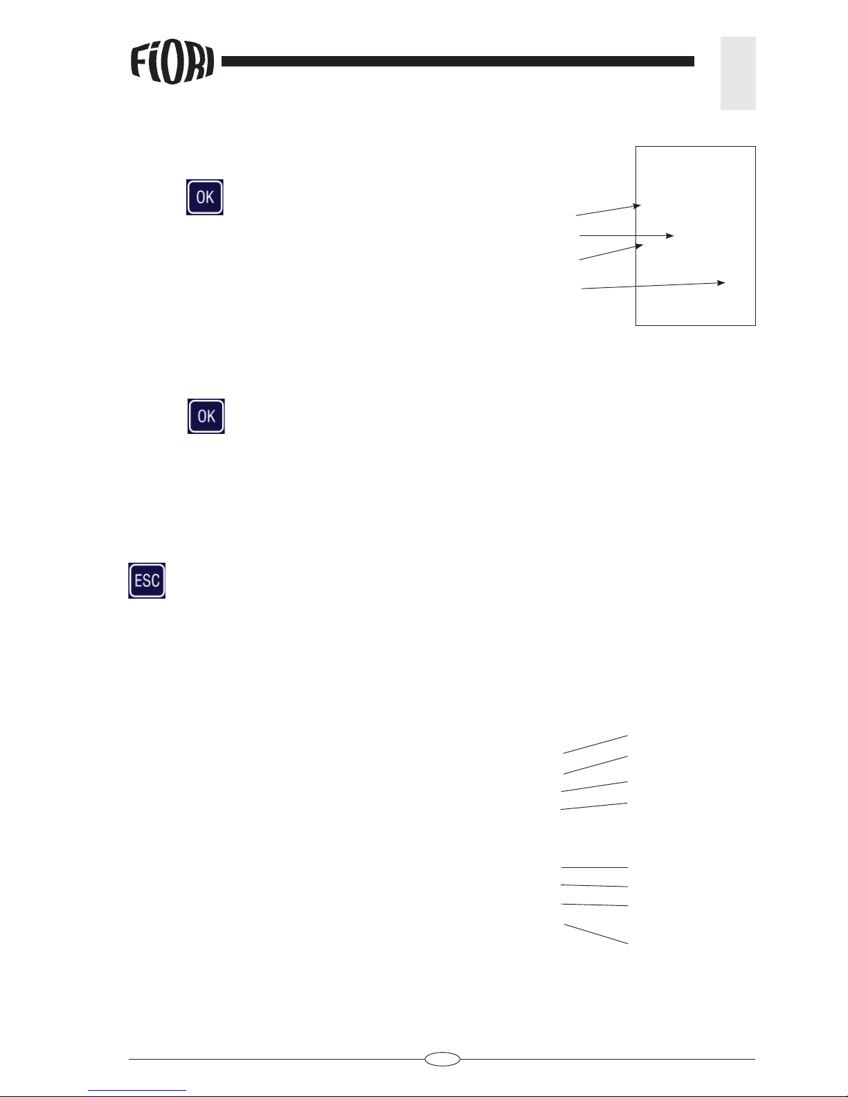
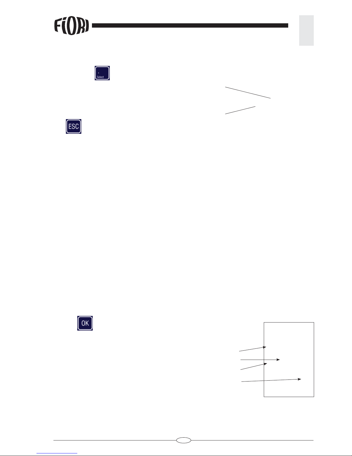
3.3 MAIN PAGE DESCRIPTION
1 - Recipe components
2 - Preset weights
3 - Measured weights
4 - Displays loading progress of the selected com-
ponent
5 - Zoom of PRESET and MEASURE values of the
selected component
The yellow colour and the yellow arrow highlight the
selected component
Use the navigation keys to select the product
you want to upload
3.5 TURNING OFF THE SYSTEM
From the main page: press and hold the key until it turns off.
3.4 ADJUSTING THE DISPLAY BRIGHTNESS
From the main page press the indicated keys to increase or reduce the brightness.
12
3
4
55

16
REV. 00 02/01/2015
id.:
FBC
MODE FUNCTIONS
3
Press the key to access the water management menu.
There are two different modes available for using the water:
A) Washing water
Normally used to wash the machine. The system does not count the amount of supplied water.
To activate the supply of washing water:
- Select “WASHING MODE”
- Press
or
To stop the water supply:
- Select “WASHING MODE”
- Press
again or
First stop threshold during the
water loading phase
B) Recipe water
You may set the threshold (%) at which the system will stop loading water during the fi rst loading phase.
3.6 WATER MANAGEMENT
3.7 AUTOMATIC WATER LOADING
Select the “WATER” component
Press OK
(a message is displayed)
Press OK
again to confi rm or ESC to
return to the previous step.
When the OK key is pressed, the water loading phase
starts; the loading progress is visible.
The water loading phase may be started through an
external device (Mix control); the device automatically
turns the pump off as soon as the preset value is
reached.
The water loading phase is carried out until the
set threshold is reached (e.g. 70%).
The remaining water will be loaded at the end of the loading phase by repeating the automatic water
loading operation.
3.8 MANUALLY LOADING A COMPONENT
Press the navigation keys to select the
desired component. Manually insert the
component in the drum .
Press the manual loading key.
A
B

17
REV. 00 02/01/2015
id.:
FBC
MODE FUNCTIONS
3
3.9 LOADING COMPONENTS THROUGH WEIGHING
The required engine speed is 2000 revs/min
- Select the desired component
- Load the component into the bucket.
- Withdraw the bucket (A)
- Lift the bucket maintaining a constant speed.
- Repeat the operation until the preset value is reached.
During the fi rst weighing a lower
value has been reached and
therefore the operation
The preset value has been exceeded
The red bar indicates an overload
The following alarm message is displayed:
excessive load
3.11 CANCELLING LAST WEIGHING
If the preset weighing value is exceeded, before pouring the material you may:
Press the indicated key to cancel the weighing, then lower the bucket to pour some material and
repeat the loading operation of the component through weighing.
3.10 LOADING PROGRESS INDICATORS
The loading progress for each individual component is displayed by means of:
- loading progress bar (from 50% to 100%)
- progressive acoustic signal (from 50% to 100%)
A screen will be displayed, in which the user will input
the amount of material to be loaded: the number in
green represents the recipe PRESET, whereas the
number in yellow indicates the total amount of material
to be loaded. Input the desired amount and press OK
to confi rm.
A

18
REV. 00 02/01/2015
id.:
FBC
MODE FUNCTIONS
3
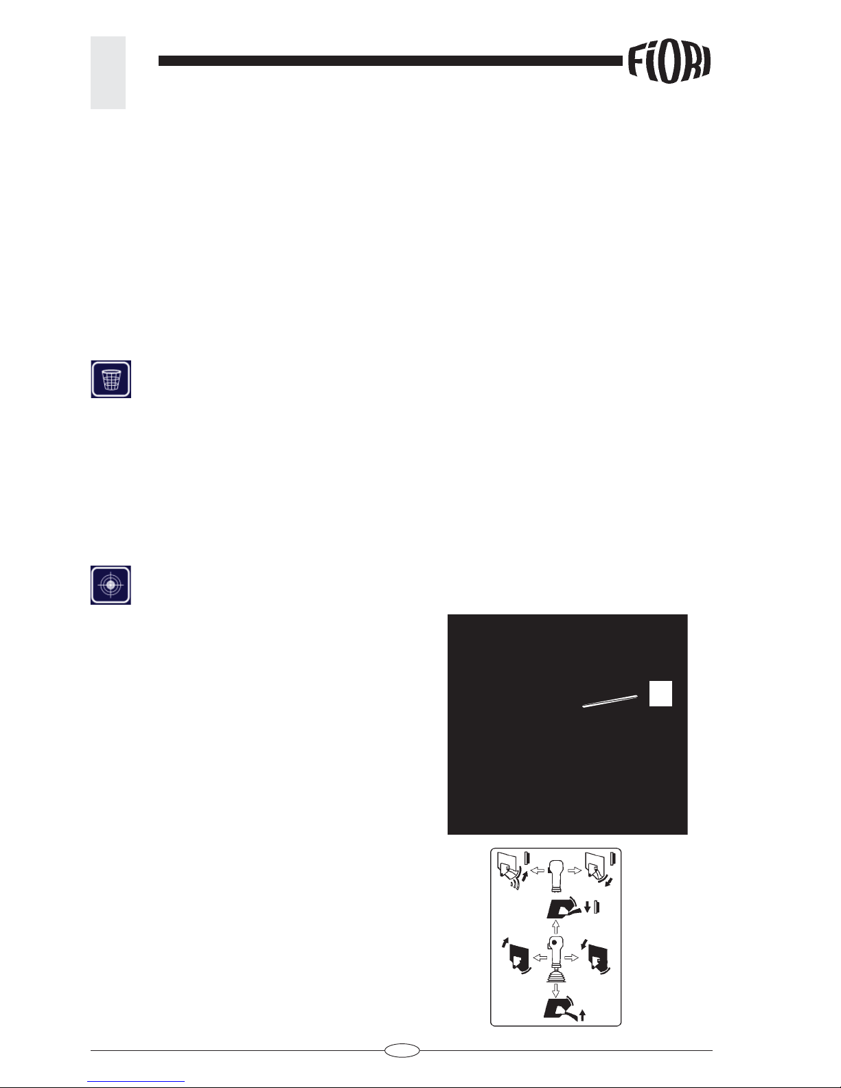
3.12 TIP-OFF (dynamic weighing)
If the preset weighing value is exceeded, before pouring the material you may:
Press the indicated key to shift to the dynamic reading, then open the pouring door located on the
bucket and pour the material until the preset value is reached.
Once the preset loading progress value is reached, as
long as it falls within the set tolerance limits, the bar
becomes green
press OK
to confi rm the end of the TIP OFF and pour the product from the drum.
Continue loading the other components by completing the recipe.
Complete the mixing of the fi nal product and pour it.
Press the button (A) on the joystick and shift it to the
left to open the hydraulic loader hatch and unload the
quantity of material necessary to reach the required
weight.
Shift the joystick to the right to close the hatch.
N.B.: Do not move the arm during tip-off; take into
account the weight shown in position ‘1’, always moving
the bucket to the same point where it was at the time of
activating the tip-off function.
N .B.: the precision of the weight in “Tip-Off” mode is
usually less than the one in standard conditions
A

19
REV. 00 02/01/2015
id.:
FBC
MODE FUNCTIONS
3
3.13 BAG-COUNTING FUNCTION
Select the component CEMENT and press the key .
Lower the arm.
Lift the arm back up until the STOP signal is displayed.
Input the weight value of each single bag (25, 30, 42.5,
…...).
Press OK
.
The system will indicate the number of bags to be
loaded.
After reaching the number of bags indicated, press OK
and load the material.
Number of bags
to be loaded
Number of bags
loaded
3.14 RESETTING MEASURED WEIGHTS
To start a new recipe
Press and hold the C
key until the cancellation message is displayed.
Press OK
to reset
All values have been reset
You may now start loading the components for a new
recipe.

20
REV. 00 02/01/2015
id.:
FBC
MODE FUNCTIONS
3
3.15 COMPLETING WATER LOADING
After loading all the recipe components, the water cycle needs to be completed by repeating the steps described
in paragraph 3.6.
3.16 PRINT MENU
Press 1 to access the print menu.
Press SELECT
to select the mixing you want to print.
Press 0
to deselect
press the SELECT
key + Arrows for multiple selections,
Press 0
+ arrows for multiple deselections,
select all items by pressing and holding down the SELECT
key,
deselect all items by pressing 0
and holding it down.
List of mixings performed: (Date and time of beginning
of mixing cycle)
The dot indicates that the recipe has not been printed
yet
Progressive number
Once you have selected the recipe you want to print,
press OK
or printing key 1 .
If multiple selections have been made, printing will be
performed in succession.
Press ESC
to return to the recipe page

21
REV. 00 02/01/2015
id.:
FBC
MODE FUNCTIONS
3
1 - Machine code
2 - Operator code
3 - Recipe name
4 - Recipe data
5 - Component marker
OTHER MARKERS
*a: component with loaded weight outside the set tolerance limits
*b: component loaded despite the weighing error signalled by the device
*c: indicates that some components have been manually loaded
5
1
2
3
4
Key 6 to access the help page where all the
function keys are explained.
ESC
to return to the main page
3.18 ALARMS PAGE
If any alarms are present, they may be displayed by
pressing key 9
( refer to chapter “ALARM LIST”).
Alarm warnings are signalled as following:
- alarm triangle on the right upper part of the screen
- acoustic alarm
3.17 HELP PAGE

22
REV. 00 02/01/2015
id.:
FBC
MODE FUNCTIONS
3
3.19 CALIBRATING THE TARE
It is a test that needs to be performed daily in order to
ensure the proper functioning of the weighing system.
TEST/CALIBRATION
To perform the device calibration
- Press 0
, hold it down for a few seconds then
press OK
or select TEST/CALIBRATION from the FUNCTIONS
menu.
- The “CAUTION....” message is displayed
operate as follows:
The maximum machine tilting must be <0.5° (frontal
axis) The engine speed must be 2000 rpm
TEST
1) Slowly lower the boom
2) Withdraw the bucket (A)
3) Lift the boom back up at a constant speed.
If the value displayed differs from zero (60 in this
instance), then the tare needs to be calibrated.
- Press OK
to shift to the calibration mode
TARE CALIBRATION
A

23
REV. 00 02/01/2015
id.:
FBC
MODE FUNCTIONS
3
Step 1/3
- Ensure that the bucket is empty
- Slowly lower the boom
- Withdraw the bucket (A)
- Lift the boom at a constant speed
Step 2/3
- Check that the bucket is empty
- Slowly lower the boom
- Withdraw the bucket (A)
- Lift the boom back up
Step 3/3
- Check that the bucket is empty
- Slowly lower the boom
- Withdraw the bucket (A)
- Lift the boom back up
If during calibration the device detects any faults, it will ask to repeat the 3 calibration steps.

24
REV. 00 02/01/2015
id.:
FBC
MODE FUNCTIONS
3
3.20 ADDITIONAL FUNCTIONS
More functions may be accessed from the recipe page:
Press the specifi ed key to access the function
menu:
PRINT DATA
To access the list of receipts corresponding to the
recipes stored;
from the menu you can select the print function or press
ESC
to return to the previous page
RESET WEIGHT
Is equivalent to the “C” key in the main page; to reset
weights
EDIT COMPONENT
For the foreman only; password required (par. 4.3)
PRINT DAILY REPORT
To print a daily report indicating the weights of the
components loaded during the current day;
press OK to print
Machine ID code
Date
Time
Weights of the components loaded during the day
SYSTEM INFO
To view system information
HTS code
Serial number
Firmware version
USB fi rmware version
INSTRUMENT DATA
Hours of operation
Weighings performed
Schedule of next calibration (hours)
Schedule of next calibration (weighings)
Press ESC several times to return to the main working page.
par. 3.19

25
REV. 00 02/01/2015
id.:
3
CBV STANDARD
MODE FUNCTIONS
The system is set to operate on various recipes, with
water compensation in the hygroscopic components. It
can also monitor the quality of the mixing and manage
automatically both the water and additive pumps.
3.1 TURN ON
Press and hold the key until the start page is displayed.
The start page is displayed for a few seconds,
3.2 ACCESSING THE FUNCTIONS
Enter the user identifi cation code (max. 4 digits).
Press the OK
key to confi rm.
Press ESC
to skip.
3.3 MAIN PAGE DESCRIPTION
1 - Selected recipe
2 - Volume to be produced
3 - Mixing time
4 - Column of the recipe components
5 - Column of the preset values calculated based
on the volume to be produced
6 - Column of the values measured for each indi-
vidual component
7 - Line of total amounts (total weight to be pro-
duced and total weight measured)
8 - Selected component
9 - Loading progress bar
10 - Preset value of the selected component
11 - Measured value of the selected component
The yellow colour and the yellow arrow highlight the
selected component
Use the navigation keys to select the product
you want to upload
3.4 ADJUSTING THE DISPLAY BRIGHTNESS
From the main page press the indicated keys to increase or reduce the brightness.
3.5 TURNING OFF THE SYSTEM
From the main page: press and hold the key until it turns off.
12
3
4
5
6
7
8
9
10 11

26
REV. 00 02/01/2015
id.:
CBV STANDARD
MODE FUNCTIONS
3
3.6 SELECTING A RECIPE
Press the “select” key
select “SELECT MIX”
Press OK
: Recipe 1 is displayed
Use the UP/DOWN arrow keys to display all set recipes
Select the recipe and press OK
to confi rm.
3.7 MOISTURE OF AGGREGATES
Once the recipe has been selected, the system asks you to defi ne the humidity of the hygroscopic
aggregates.
This data will determine a compensation in the volume of the components involved
Press OK
to go to the HUMIDITY page
Enter the humidity percentage in the fi eld, ranging from 0% to +20%.
Press OK
to confi rm.
Press ESC
to return to the recipe and start loading the components

27
REV. 00 02/01/2015
id.:
3
CBV STANDARD
MODE FUNCTIONS
3.8 SELECTING THE VOLUME
From the “FUNCTION” menu select “SETUP VOLUME”
Press OK
to edit the volume
Enter the volume you want to produce
Press OK
to confi rm and return to the
“FUNCTION” menu
press ESC
from the “FUNCTION” menu to go
back to the main page (recipe)
To set up the volume to produce from
the selected recipe
Vehicle limits
Once the humidity percentage has been
entered, the device recalculates the hygroscopic
components and water values
3.9 AUTOMATIC WATER LOADING
Select the “WATER” component
Press OK
(a message is displayed)
Press OK
again to confi rm or ESC to
return to the previous step.
When the OK key is pressed, the water loading phase
starts; the loading progress is visible.
The water loading phase may be started through an
external device (Mix control); the device automatically
turns the pump off as soon as the preset value is
reached.
The water loading phase is carried out until the
set threshold is reached (e.g. 70%).
The remaining water will be loaded at the end of the loading phase by repeating the automatic water
loading operation.
Select the next component (e.g. CEMENT)

28
REV. 00 02/01/2015
id.:
CBV STANDARD
MODE FUNCTIONS
3
3.11 AUTOMATIC WATER LOADING
Press the navigation keys to select the
desired component. Manually insert the
component in the drum, until you reach the
quantity defi ned in the PRESET fi eld.
Once the 20% of the WATER-CEMENT loading
value is reached, the mixing timer starts.
Press the manual loading key.
A screen will be displayed, in which the user will input
the amount of material to be loaded: the number in
green represents the recipe PRESET, whereas the
number in yellow indicates the total amount of material
to be loaded. Input the desired amount and press OK
to confi rm.
3.10 LOADING COMPONENTS THROUGH WEIGHING
The required engine speed is 2000 revs/min
- Select the desired component
- Load the component into the bucket.
- Withdraw the bucket (A)
- Lift the bucket maintaining a constant speed.
- Repeat the operation until the preset value is reached.
- If the loaded value exceeds the PRESET value, the
procedure described in “cancel last weight” “Tip Off”
may be followed.
During the fi rst weighing a lower value has
been reached and therefore the operation
The preset value has been exceeded
The red bar indicates an overload
The following alarm message is displayed:
excessive load
A

29
REV. 00 02/01/2015
id.:
3
CBV STANDARD
MODE FUNCTIONS
3.13 CANCELLING LAST WEIGHING
If the preset weighing value is exceeded, before pouring the material you may:
Press the indicated key to cancel the weighing, then lower the bucket to pour some material and
repeat the loading operation of the component through weighing.
3.14 TIP-OFF (dynamic weighing)
If the preset weighing value is exceeded, before pouring the material you may:
Press the indicated key to shift to the dynamic reading, then open the pouring door located on the
bucket and pour the material until the preset value is reached.
Press the button (A) on the joystick and shift it to the
left to open the hydraulic loader hatch and unload the
quantity of material necessary to reach the required
weight.
Shift the joystick to the right to close the hatch.
N.B.: Do not move the arm during tip-off; take into
account the weight shown in position ‘1’, always moving
the bucket to the same point where it was at the time of
activating the tip-off function.
N .B.: the precision of the weight in “Tip-Off” mode is
usually less than the one in standard conditions
3.12 LOADING PROGRESS INDICATORS
The loading progress for each individual component is displayed by means of:
- loading progress bar (from 50% to 100%)
- progressive acoustic signal (from 50% to 100%)
A

30
REV. 00 02/01/2015
id.:
CBV STANDARD
MODE FUNCTIONS
3
3.15 AUTOMATICALLY LOADING THE ADDITIVE
The additive is loaded by means of the automatic
management of the relevant pump, in a similar manner
than water loading.
Select “ADDITIVE” Press OK
.
A warning message is displayed
Press OK
to confi rm.
The device will automatically start the additive pump.
The device will automatically stop the additive pump as
soon as the preset value is reached.
Once the preset loading progress value is reached, as long as it falls within the set tolerance limits, the bar
becomes green
press OK
to confi rm the end of the TIP OFF and pour the product from the drum.
Continue loading the other components by completing the recipe.
Complete the mixing of the fi nal product and pour it.

31
REV. 00 02/01/2015
id.:
3
CBV STANDARD
MODE FUNCTIONS
3.16 COMPLETING WATER LOADING
Once all recipe components have been loaded, the water loading needs to be completed.
Select “WATER”.
Press OK
(a warning message is displayed).
Press OK
to confi rm.
The water pump is started and loading completion is performed.
The mix. is complete.
When the device detects the start of the mixing
phase, the START MIXING DETECT message
is displayed.
The start of the mixing phase is detected only after all
components required by the recipe have been loaded.

32
REV. 00 02/01/2015
id.:
CBV STANDARD
MODE FUNCTIONS
3
3.18 VIEWING THE MIXING STATUS
Press key 2
N.B. If the values are displayed in yellow, it means that the mix is not ready yet.
The RPM fi eld may be displayed in three different
colours:
Green: speed is suitable
Yellow: speed is too slow
Red: speed is too fast
Revolutions performed by
the drum during the mixing
phase
Number of revolutions to be performed
Maximum mixing
pressure
Drum rotation
speed
Mixing revolutions
progress
Differential progress of last mixing revolution
Drum rotation
direction (mixing/ pouring)
3.17 BAG-COUNTING FUNCTION
Select the component CEMENT and press the key .
Lower the arm.
Lift the arm back up until the STOP signal is displayed.
Input the weight value of each single bag (25, 30, 42.5,
…...).
Press OK
.
The system will indicate the number of bags to be
loaded.
After reaching the number of bags indicated, press OK
and load the material.
Number of bags
to be loaded
Number of bags
loaded

33
REV. 00 02/01/2015
id.:
3
CBV STANDARD
MODE FUNCTIONS
3.19 POURING THE MIX
Set the drum rotation in the pouring position; the
following message is displayed
Beginning of the pouring phase has
been detected
when the device detects the end of the pouring phase,
the following message is displayed
End of pouring phase message
Press ESC to return to the recipe page
3.20 RESETTING THE VALUES OF THE WEIGHTS MEASURED
Press and hold the C
key until the cancellation
message is displayed.
Press OK
to reset the recipe data; by doing this
you may perform the same recipe again or perform
other recipes in the data storage.
All values have been reset

34
REV. 00 02/01/2015
id.:
CBV STANDARD
MODE FUNCTIONS
3
3.21 PRINT MENU
Press 1 to access the print menu.
Press SELECT
to select the mixing you want to print.
Press 0
to deselect
press the SELECT
key + Arrows for multiple selections,
Press 0
+ arrows for multiple deselections,
select all items by pressing and holding down the SELECT
key,
deselect all items by pressing 0
and holding it down.
List of mixings performed: (Date and time of beginning
of mixing cycle)
Letter “X” indicates that the recipe has been selected
for printing
The dot indicates that the recipe has not been printed
yet
Progressive number
Once you have selected the recipe you want to print,
press OK
or printing key 1 .
If multiple selections have been made, printing will be
performed in succession.
Press ESC
to return to the recipe page

35
REV. 00 02/01/2015
id.:
3
CBV STANDARD
MODE FUNCTIONS
1 - Machine code
2 - Operator code
3 - Recipe name
4 - Recipe volume
5 - Start time and date of mixing cycle
6 - End time and date of mixing cycle
7 - Mixing revolutions
8 - Performed
9 - Preset
10 - Mixing time
11 - Stabilized pressure
12 – Pressure
13 - Mixing revolutions at which pressure has stabilized
14 - End time and date of pouring phase
15 - Pouring revolutions
16 - Cycle time
17 - Recipe data
18 - Component marker
19 - Specifi c weight of the additive
20 - Component typical absorption
21 - Water amount in SSA (SSD - Saturated Surface Dry)
22 - Hygroscopic aggregate data
23 - Component name
24 - Moisture %
25 - Water contained in the component
26 - Mix data
27 - Total loaded water
28 - Total hygroscopic components (SSA)
29 - Total weight
30 - Water/cement ratio
31 - Column of data set by recipes
32 - Data column
OTHER MARKERS
*a: component with loaded weight outside the set tolerance limits
*b: component loaded despite the weighing error signalled by the device
*c: indicates that some components have been manually loaded
17
26
27
1
2
3
4
5
6
7
8
9
10
11
12
13
14
15
16
18
19
22
23
20
21
28
29
30
31 32
18
24
25

36
REV. 00 02/01/2015
id.:
CBV STANDARD
MODE FUNCTIONS
3
Key 6 to access the help page where all the
function keys are explained.
ESC
to return to the main page
3.23 ALARMS PAGE
If any alarms are present, they may be displayed by
pressing key 9
( refer to chapter “ALARM LIST”).
Alarm warnings are signalled as following:
- alarm triangle on the right upper part of the screen
- acoustic alarm
3.22 HELP PAGE
3.24 CALIBRATING THE TARE
It is a test that needs to be performed daily in order to
ensure the proper functioning of the weighing system.
TEST/CALIBRATION
To perform the device calibration
- Press 0
, hold it down for a few seconds then
press OK
or select TEST/CALIBRATION from the FUNCTIONS
menu.
- The “CAUTION....” message is displayed
operate as follows:
The maximum machine tilting must be <0.5° (frontal
axis) The engine speed must be 2000 rpm

37
REV. 00 02/01/2015
id.:
3
CBV STANDARD
MODE FUNCTIONS
TEST
1) Slowly lower the boom
2) Withdraw the bucket (A)
3) Lift the boom back up at a constant speed.
If the value displayed differs from zero (60 in this
instance), then the tare needs to be calibrated.
- Press OK
to shift to the calibration mode
TARE CALIBRATION
Step 1/3
- Ensure that the bucket is empty
- Slowly lower the boom
- Withdraw the bucket (A)
- Lift the boom at a constant speed
Step 2/3
- Check that the bucket is empty
- Slowly lower the boom
- Withdraw the bucket (A)
- Lift the boom back up
Step 3/3
- Check that the bucket is empty
- Slowly lower the boom
- Withdraw the bucket (A)
- Lift the boom back up
If during calibration the device detects any faults, it will ask to repeat the 3 calibration steps.
A

38
REV. 00 02/01/2015
id.:
CBV STANDARD
MODE FUNCTIONS
3
3.26 FUNCTION MENU
Vehicle limits
Press “SELECT” from the recipe page
PRINT DATA
To access the list of receipts corresponding to the
recipes stored;
from the menu you can select the print function or
press ESC
to return to the previous page.
RESET WEIGHT
Is equivalent to the “C” key in the main page; to reset
weights.
SETUP VOLUME
To set up the volume to produce from the selected
recipe.
par. 3.6
par. 3.24
Press the key to access the water management menu.
There are two different modes available for using the water:
A) Washing water
Normally used to wash the machine. The system does not count the amount of supplied water.
To activate the supply of washing water:
- Select “WASHING MODE”
- Press
or
To stop the water supply:
- Select “WASHING MODE”
- Press
again or
First stop threshold during the
water loading phase
B) Recipe water
You may set the threshold (%) at which the system will stop loading water during the fi rst loading phase.
3.25 WATER MANAGEMENT
A
B
39
REV. 00 02/01/2015
id.:
3
CBV STANDARD
MODE FUNCTIONS
PRINT DAILY REPORT
To print a daily report indicating the weights of the
components loaded during the current day;
press OK
to print.
DOWNLOAD
select one or more fi elds
Press OK
Insert the USB memory stick
A message is displayed confi rming that the USB
memory stick has been detected and therefore the
download will start showing the transfer progress
status from 0 to 100%
Remove the USB memory stick and carefully put the
cap back in place to ensure the system protection IP
levels.
Esc to return to the FUNCTION menu.
SYSTEM INFO
To view system information
Print daily report
Machine ID code
Date
Time
Weights of the components loaded
during the day
Print all the components loaded during the day
HTS code
Serial number
Firmware version
USB fi rmware version
INSTRUMENT DATA
Hours of operation
Weighings performed
Next programming
calibration (hours)
Next programming
calibration (weighings)


41
REV. 00 02/01/2015
id.:
CBV ADVANCED
MODE FUNCTIONS
3
The system is set to operate on various recipes, with
water compensation in the hygroscopic components. It
can also monitor the quality of the mixing and manage
automatically both the water and additive pumps.
It provides information on the front and lateral tilting of
the carriage.
It sends the data to external GPS/GPRS devices.
3.1 TURN ON
Press and hold the key until the start page is displayed.
The start page is displayed for a few seconds,
3.2 ACCESSING THE FUNCTIONS
Enter the user identifi cation code (max. 4 digits).
Press the OK
key to confi rm.
Press ESC
to skip.
3.3 MAIN PAGE DESCRIPTION
1 - Selected recipe
2 - Volume to be produced
3 - Mixing time
4 - Column of the recipe components
5 - Column of the preset values calculated based
on the volume to be produced
6 - Column of the values measured for each indi-
vidual component
7 - Line of total amounts (total weight to be pro-
duced and total weight measured)
8 - Selected component
9 - Loading progress bar
10 - Preset value of the selected component
11 - Measured value of the selected component
The yellow colour and the yellow arrow highlight the
selected component
Use the navigation keys to select the product you want to upload
3.4 ADJUSTING THE DISPLAY BRIGHTNESS
From the main page press the indicated keys to increase or reduce the brightness.
3.5 TURNING OFF THE SYSTEM
From the main page: press and hold the key until it turns off.
12
3
4
5
6
7
8
9
10 11

42
REV. 00 02/01/2015
id.:
CBV ADVANCED
MODE FUNCTIONS
3
3.6 SELECTING A RECIPE
Press the “select” key
select “SELECT MIX”
Press OK
: Recipe 1 is displayed
Use the UP/DOWN arrow keys to display all set recipes
Select the recipe and press OK
to confi rm.
3.7 MOISTURE OF AGGREGATES (see section 4.3.1)
3.7.1 Manually enter the humidity percentage
Once the recipe has been selected, the system asks you to defi ne the humidity of the hygroscopic
aggregates.
This data will determine a compensation in the volume of the components involved
Press OK
to go to the HUMIDITY page
Enter the humidity percentage in the fi eld, ranging from 0% to +20%.
Press OK
to confi rm.
Press ESC
to return to the recipe and start loading the components

43
REV. 00 02/01/2015
id.:
CBV ADVANCED
MODE FUNCTIONS
3
3.7.2 Use of the Mikrolab
If you set the use of the Mikrolab and the recipe con-
tains SAND MP1...... SAND MP6 type hygroscopic
components
Press OK
to go to the HUMIDITY PAGE.
Connect the Mikrolab to the system.
Insert the selected component into the Mikrolab.
Press OK
to confi rm.
The system automatically acquires the moisture percentage.
Press ESC
to return to the recipe and start loading the components.
Once the humidity percentage has been entered, the device recalculates the hygroscopic
components and water values
Once the humidity percentage has been
entered, the device recalculates the
hygroscopic components and water values

44
REV. 00 02/01/2015
id.:
CBV ADVANCED
MODE FUNCTIONS
3
3.7.3 Use of the moisture probe
If you set the use of the moisture probe, you do not need to enter the humidity value; the system will automatically
detect it during weighing
3.8 SELECTING THE VOLUME
From the “FUNCTION” menu select “SETUP VOLUME”
Press OK
to edit the volume
Enter the volume you want to produce
Press OK
to confi rm and return to the
“FUNCTION” menu
press ESC
from the “FUNCTION” menu to go
back to the main page (recipe)
To set up the volume to produce from
the selected recipe
Vehicle limits
3.9 AUTOMATIC WATER LOADING
Select the “WATER” component
Press OK
(a message is displayed)
Press OK
again to confi rm or ESC to
return to the previous step.
When the OK key is pressed, the water loading phase
starts; the loading progress is visible.
The water loading phase may be started through an
external device (Mix control); the device automatically
turns the pump off as soon as the preset value is
reached.
The water loading phase is carried out until the
set threshold is reached (e.g. 70%).
The remaining water will be loaded at the end of the loading phase by repeating the automatic water
loading operation.
Select the next component (e.g. CEMENT)

45
REV. 00 02/01/2015
id.:
CBV ADVANCED
MODE FUNCTIONS
3
3.11 AUTOMATIC WATER LOADING
Press the navigation keys to select the
desired component. Manually insert the
component in the drum, until you reach the
quantity defi ned in the PRESET fi eld.
Once the 20% of the WATER-CEMENT loading
value is reached, the mixing timer starts.
Press the manual loading key.
A screen will be displayed, in which the user will input
the amount of material to be loaded: the number in
green represents the recipe PRESET, whereas the
number in yellow indicates the total amount of material
to be loaded. Input the desired amount and press OK
to confi rm.
3.10 LOADING COMPONENTS THROUGH WEIGHING
The required engine speed is 2000 revs/min
- Select the desired component
- Load the component into the bucket.
- Withdraw the bucket (A)
- Lift the bucket maintaining a constant speed.
- Repeat the operation until the preset value is reached.
- If the loaded value exceeds the PRESET value, the
procedure described in “cancel last weight” “Tip Off”
may be followed.
During the fi rst weighing a lower value has
been reached and therefore the operation
The preset value has been exceeded
The red bar indicates an overload
The following alarm message is displayed:
excessive load
A
46
REV. 00 02/01/2015
id.:
CBV ADVANCED
MODE FUNCTIONS
3
3.13 CANCELLING LAST WEIGHING
If the preset weighing value is exceeded, before pouring the material you may:
Press the indicated key to cancel the weighing, then lower the bucket to pour some material and
repeat the loading operation of the component through weighing.
3.14 TIP-OFF (dynamic weighing)
If the preset weighing value is exceeded, before pouring the material you may:
Press the indicated key to shift to the dynamic reading, then open the pouring door located on the
bucket and pour the material until the preset value is reached.
Press the button (A) on the joystick and shift it to the
left to open the hydraulic loader hatch and unload the
quantity of material necessary to reach the required
weight.
Shift the joystick to the right to close the hatch.
N.B.: Do not move the arm during tip-off; take into
account the weight shown in position ‘1’, always moving
the bucket to the same point where it was at the time of
activating the tip-off function.
N .B.: the precision of the weight in “Tip-Off” mode is
usually less than the one in standard conditions
3.12 LOADING PROGRESS INDICATORS
The loading progress for each individual component is displayed by means of:
- loading progress bar (from 50% to 100%)
- progressive acoustic signal (from 50% to 100%)
A

47
REV. 00 02/01/2015
id.:
CBV ADVANCED
MODE FUNCTIONS
3
Once the preset loading progress value is reached, as long as it falls within the set tolerance limits, the bar
becomes green
press OK
to confi rm the end of the TIP OFF and pour the product from the drum.
Continue loading the other components by completing the recipe.
Complete the mixing of the fi nal product and pour it.
3.15 AUTOMATICALLY LOADING THE ADDITIVE
The additive is loaded by means of the automatic
management of the relevant pump, in a similar manner
than water loading.
Select “ADDITIVE” Press OK
.
A warning message is displayed
Press OK
to confi rm.
The device will automatically start the additive pump.
The device will automatically stop the additive pump as
soon as the preset value is reached.

48
REV. 00 02/01/2015
id.:
CBV ADVANCED
MODE FUNCTIONS
3
3.16 COMPLETING WATER LOADING
Once all recipe components have been loaded, the water loading needs to be completed.
Select “WATER”.
Press OK
(a warning message is displayed).
Press OK
to confi rm.
The water pump is started and loading completion is performed.
The mix. is complete.
When the device detects the start of the mixing
phase, the START MIXING DETECT message
is displayed.
The start of the mixing phase is detected only after all
components required by the recipe have been loaded.
3.17 BAG-COUNTING FUNCTION
Select the component CEMENT and press the key .
Lower the arm.
Lift the arm back up until the STOP signal is displayed.
Input the weight value of each single bag (25, 30, 42.5,
…...).
Press OK
.

49
REV. 00 02/01/2015
id.:
CBV ADVANCED
MODE FUNCTIONS
3
3.18 VIEWING THE MIXING STATUS
Press key 2
N.B. If the values are displayed in yellow, it means that the mix is not ready yet.
The RPM fi eld may be displayed in three different
colours:
Green: speed is suitable
Yellow: speed is too slow
Red: speed is too fast
Revolutions performed by
the drum during the mixing
phase
Number of revolutions to be performed
Maximum mixing
pressure
Drum rotation
speed
Mixing revolutions
progress
Differential progress of last mixing revolution
Drum rotation
direction (mixing/ pouring)
3.19 POURING THE MIX
Set the drum rotation in the pouring position; the
following message is displayed
Beginning of the pouring phase has
been detected
when the device detects the end of the pouring phase,
the following message is displayed
End of pouring phase message
Press ESC to return to the recipe page
Number of bags
to be loaded
Number of bags
loaded
The system will indicate the number of bags to be
loaded.
After reaching the number of bags indicated, press OK
and load the material.

50
REV. 00 02/01/2015
id.:
CBV ADVANCED
MODE FUNCTIONS
3
3.20 RESETTING THE VALUES OF THE WEIGHTS MEASURED
Press and hold the C
key until the cancellation
message is displayed.
Press OK
to reset the recipe data; by doing this
you may perform the same recipe again or perform
other recipes in the data storage.
All values have been reset
3.21 PRINT MENU
Press 1 to access the print menu.
Press SELECT
to select the mixing you want to print.
Press 0
to deselect
press the SELECT
key + Arrows for multiple selections,
Press 0
+ arrows for multiple deselections,
select all items by pressing and holding down the SELECT
key,
deselect all items by pressing 0
and holding it down.
List of mixings performed: (Date and time of beginning
of mixing cycle)
Letter “X” indicates that the recipe has been selected
for printing
The dot indicates that the recipe has not been printed
yet
Progressive number
Once you have selected the recipe you want to print,
press OK
or printing key 1 .
If multiple selections have been made, printing will be
performed in succession.
Press ESC
to return to the recipe page

51
REV. 00 02/01/2015
id.:
CBV ADVANCED
MODE FUNCTIONS
3
1 - Machine code
2 - Operator code
3 - Recipe name
4 - Recipe volume
5 - Start time and date of mixing cycle
6 - End time and date of mixing cycle
7 - Mixing revolutions
8 - Performed
9 - Preset
10 - Mixing time
11 - Stabilized pressure
12 – Pressure
13 - Mixing revolutions at which pressure has stabilized
14 - End time and date of pouring phase
15 - Pouring revolutions
16 - Cycle time
17 - Recipe data
18 - Component marker
19 - Specifi c weight of the additive
20 - Component typical absorption
21 - Water amount in SSA (SSD - Saturated Surface Dry)
22 - Hygroscopic aggregate data
23 - Component name
24 - Moisture %
25 - Water contained in the component
26 - Mix data
27 - Total loaded water
28 - Total hygroscopic components (SSA)
29 - Total weight
30 - Water/cement ratio
31 - Column of data set by recipes
32 - Data column
OTHER MARKERS
*a: component with loaded weight outside the set tolerance limits
*b: component loaded despite the weighing error signalled by the device
*c: indicates that some components have been manually loaded
17
26
27
1
2
3
4
5
6
7
8
9
10
11
12
13
14
15
16
18
19
22
23
20
21
28
29
30
31 32
18
24
25

52
REV. 00 02/01/2015
id.:
CBV ADVANCED
MODE FUNCTIONS
3
Key 6 to access the help page where all the
function keys are explained.
ESC
to return to the main page
3.23 ALARMS PAGE
If any alarms are present, they may be displayed by
pressing key 9
( refer to chapter “ALARM LIST”).
Alarm warnings are signalled as following:
- alarm triangle on the right upper part of the screen
- acoustic alarm
3.22 HELP PAGE
3.24 CALIBRATING THE TARE
It is a test that needs to be performed daily in order to
ensure the proper functioning of the weighing system.
TEST/CALIBRATION
To perform the device calibration
- Press 0
, hold it down for a few seconds then
press OK
or select TEST/CALIBRATION from the FUNCTIONS
menu.
- The “CAUTION....” message is displayed
operate as follows:
The maximum machine tilting must be <0.5° (frontal
axis) The engine speed must be 2000 rpm

53
REV. 00 02/01/2015
id.:
CBV ADVANCED
MODE FUNCTIONS
3
TEST
1) Slowly lower the boom
2) Withdraw the bucket (A)
3) Lift the boom back up at a constant speed.
If the value displayed differs from zero (60 in this
instance), then the tare needs to be calibrated.
- Press OK
to shift to the calibration mode
TARE CALIBRATION
Step 1/3
- Ensure that the bucket is empty
- Slowly lower the boom
- Withdraw the bucket (A)
- Lift the boom at a constant speed
Step 2/3
- Check that the bucket is empty
- Slowly lower the boom
- Withdraw the bucket (A)
- Lift the boom back up
Step 3/3
- Check that the bucket is empty
- Slowly lower the boom
- Withdraw the bucket (A)
- Lift the boom back up
If during calibration the device detects any faults, it will ask to repeat the 3 calibration steps.
A

54
REV. 00 02/01/2015
id.:
CBV ADVANCED
MODE FUNCTIONS
3
Press the key to access the water management menu.
There are two different modes available for using the water:
A) Washing water
Normally used to wash the machine. The system does not count the amount of supplied water.
To activate the supply of washing water:
- Select “WASHING MODE”
- Press
or
To stop the water supply:
- Select “WASHING MODE”
- Press
again or
First stop threshold during the
water loading phase
B) Recipe water
You may set the threshold (%) at which the system will stop loading water during the fi rst loading phase.
3.25 WATER MANAGEMENT
A
B
55
REV. 00 02/01/2015
id.:
CBV ADVANCED
MODE FUNCTIONS
3
3.25 FUNCTION MENU
par. 3.6
par. 3.24
Press “SELECT”
from the recipe page
PRINTING DATA
To access the list of receipts corresponding to the recipes stored;
from the menu you can select the print function or press
ESC
to return to the previous page
RESET WEIGHTS
Is equivalent to the “C” key in the main page; to reset
weights
SET UP VOLUME
To set up the volume to produce from the selected
recipe
DAILY REPORT
To print a daily report indicating the weights of the components loaded during the current day;
press OK
to print
Machine limits
Print daily report
Machine ID code
Date
Time
Weights of the
components loaded
during the day

56
REV. 00 02/01/2015
id.:
CBV ADVANCED
MODE FUNCTIONS
3
DOWNLOAD
Select one or more fi elds
Press OK Insert the USB memory stick
A message is displayed confi rming that the USB mem-
ory stick has been detected; the download will start
showing the transfer progress status from 0 to 100%
Remove the USB memory stick and carefully put the
cap back in place to ensure the system protection IP
levels.
Esc
to return to the FUNCTION menu.
DETECTING THE MACHINE TILTING
Select the “MACHINE TILTING” fi eld
Press OK
; the tilting graphic page is displayed.
COLOURS:
green = values within tolerance
yellow = Next to the machine overturning danger
threshold
red = danger of machine overturning
N.B: the yellow and red signals are accompanied by a
progressive acoustic alarm depending on the level of
danger.
SYSTEM INFO
To view system information
left tilting
back tilting
Tilting values
FR= front LA= lateral
Print all the components loaded during the day
HTS code
Serial number
Firmware version
USB fi rmware version
INSTRUMENT DATA
Hours of operation
Weighings performed
Schedule of next
calibration (hours)
Schedule of next
calibration (weighings)
3.27 DATA SENT TO GPS AND GPRS SYSTEMS
The following data are sent:
- The receipt printing data, each time that a recipe processing cycle is completed.
- General alarms
- drum rotation pressures.

57
REV. 00 02/01/2015
id.:
4
FBC
MODE FUNCTIONS FOR THE FOREMAN ONLY
4.1 MENU SETTINGS
- Go to the main page (recipe)
- Press and hold the arrow key (>)
and then
the SELECT
key.
In the SETTING page you may change:
- Language
- unit of measurement (kg) or pounds (lbs)
Select the “FOREMAN” fi eld and then press OK
.
Enter the foreman password (the default password is 0, it may be changed at a later time).
4.2 MENU FOREMAN

58
REV. 00 02/01/2015
id.:
FBC
MODE FUNCTIONS FOR THE FOREMAN ONLY
4
4.3 COMPONENTS AND RECIPES
To set or modify the list of components to be used in the recipe.
Some components are preset by the manufacturer, however all components may be set or modifi ed.
Up to 32 components may be set
In the main page (used by the operator) only the components with weight
different from zero will be displayed .
The fi rst component must always be WATER
component type:
Water = water,
---- = generic
progressive index
component name
value (kg) to be loaded to run the
recipe)
To write or change the name of a component
- Use the arrow
keys to select the component
- Press C
several times to delete the name and then write it again.
- Press OK
to confi rm
To change the preset value
- Select the value you want to change
- Enter the new value
- Press OK
to confi rm
- Press ESC
to return to the previous menu

59
REV. 00 02/01/2015
id.:
4
FBC
MODE FUNCTIONS FOR THE FOREMAN ONLY
4.5 MACHINE DIAGNOSTICS
The operator may access these functions only if requested, and under the supervision of the technical
assistance service.
4.6 SYSTEM DIAGNOSTICS
The operator may access these functions only if requested, and under the supervision of the technical
assistance services.
4.7 PASSWORD CHANGE
Change the foreman password (the default password is set to 0)
- Press OK
to access the page.
- Select “FOREMAN PASSW” and press OK
.
- Type the new password.
- Press OK
to confi rm.
4.4 SYSTEM CONFIGURATION
Scroll UP/DOWN with the arrow keys until the desired operating mode is reached, then press the
SELECT key
.

60
REV. 00 02/01/2015
id.:
FBC
MODE FUNCTIONS FOR THE FOREMAN ONLY
4
4.8 SETTING THE CLOCK
To set the clock
- Press OK
to access the page.
- Select the various fi elds and enter the required information:
Hours, minutes, year, month, day”.
- Press OK
to confi rm.
4.9 PRINTING THE PARAMETERS
To print all system parameters - normally required during technical assistance services.

61
REV. 00 02/01/2015
id.:
4
CBV STANDARD
MODE FUNCTIONS FOR THE FOREMAN ONLY
4.1 MENU SETTINGS
- Go to the main page (recipe)
- Press and hold the arrow key (>)
and then
the SELECT
key.
In the SETTING page you may change:
- Language
- unit of measurement (kg) or pounds (lbs)
Select the “FOREMAN” fi eld and then press OK
.
Enter the foreman password (the default password is 0, it may be changed at a later time).
4.2 MENU FOREMAN

62
REV. 00 02/01/2015
id.:
CBV STANDARD
MODE FUNCTIONS FOR THE FOREMAN ONLY
4
4.3 COMPONENTS AND RECIPES
4.3.1 Entering the components
To set or change the list of the components to be used in the recipes.
Some components are preset by the manufacturer, however all components may be set or
modifi ed.
Up to 32 components may be set.
To write or change the name of a component
- Use the arrow keys to select the component
- Press C
several times to delete the name and
then write it again.
- Press OK
to confi rm.
To select the component type
- use the UP/DOWN arrows .
The components are indicated as follows:
1 - TP Column
(--) Generic component
W: (Water) water type component; it will be loaded by means of water pump.
C: (Cement) cement type component (necessary to identify the 20% water and cement level).
A: (Additives) identifi ed to activate the corresponding pump. In the SG column (Specifi c Gravity)
the specifi c weight must be specifi ed.
S: (Sand) Hygroscopic component on which the automatic water compensation will be performed.
2 - SG (Special Gravity) column the specifi c weight value of A type materials (additives) is set) (Kg/l).
3 - SSA column it is the typical absorption value of any S type material (sand).
4 - LD column pump function management: L1 water pump, L2 1st additive, L3 2nd additive
- Press ESC
to return to the menu.
12 34

63
REV. 00 02/01/2015
id.:
4
CBV STANDARD
MODE FUNCTIONS FOR THE FOREMAN ONLY
4.3.2 Creating mixes
To create new recipes or edit the existing ones.
To browse through all recipes
(up to 16 recipes are processed)
Weight needed to obtain 1 cube metre of recipe
Component code
To create a new recipe
- Select a recipe (e.g. No. 2).
- Press OK
.
- Press the C
key several times to cancel the recipe name.
- Type the new recipe name (e.g. Mix2)
- Press OK
to confi rm; the cursor moves to the fi rst component. Use the arrow keys (> <) to select the
component.
- Press OK
to confi rm.
- Enter the component weight.
The weights of the components entered in the RW column must be those needed to produce 1 cube
metre of material.
The amount of additive must be expressed in litres, those needed to obtain 1 cube metre of material
- Press OK
to confi rm.

64
REV. 00 02/01/2015
id.:
CBV STANDARD
MODE FUNCTIONS FOR THE FOREMAN ONLY
4
4.3.3 Downloading components and recipes
To download the data on a USB memory stick
- Open the USB cap and insert the USB memory stick
- Wait for all data to be transferred.
- Press ESC
to exit at the end of the step.
- Do not remove the USB memory stick during data
transfer.
4.3.4 Uploading components and recipes
To download the data on a USB memory stick
- Open the USB cap and insert the USB memory stick
- Wait for all data, recipes and components to be
transferred.
- Remove the USB memory stick.
- Press ESC
to exit at the end of the step.
- Do not remove the USB memory stick during data
transfer.

65
REV. 00 02/01/2015
id.:
4
CBV STANDARD
MODE FUNCTIONS FOR THE FOREMAN ONLY
4.5 MACHINE DIAGNOSTICS
The operator may access these functions only if requested, and under the supervision of the technical
assistance service.
4.6 SYSTEM DIAGNOSTICS
The operator may access these functions only if requested, and under the supervision of the technical
assistance services.
4.7 PASSWORD CHANGE
Change the foreman password (the default password is set to 0)
- Press OK
to access the page.
- Select “FOREMAN PASSW” and press OK
.
- Type the new password.
- Press OK
to confi rm.
4.4 SYSTEM CONFIGURATION
Scroll UP/DOWN with the arrow keys until the desired operating mode is reached, then press the
SELECT key
.

66
REV. 00 02/01/2015
id.:
CBV STANDARD
MODE FUNCTIONS FOR THE FOREMAN ONLY
4
4.8 SETTING THE CLOCK
To set the clock
- Press OK
to access the page.
- Select the various fi elds and enter the required information:
Hours, minutes, year, month, day”.
- Press OK
to confi rm.
4.9 PRINTING THE PARAMETERS
To print all system parameters - normally required during technical assistance services.

67
REV. 00 02/01/2015
id.:
4
CBV ADVANCED
MODE FUNCTIONS FOR THE FOREMAN ONLY
4.1 MENU SETTINGS
- Go to the main page (recipe)
- Press and hold the arrow key (>)
and then
the SELECT
key.
In the SETTING page you may change:
- Language
- unit of measurement (kg) or pounds (lbs)
Select the “FOREMAN” fi eld and then press OK
.
Enter the foreman password (the default password is 0, it may be changed at a later time).
4.2 MENU FOREMAN

68
REV. 00 02/01/2015
id.:
4
CBV ADVANCED
MODE FUNCTIONS FOR THE FOREMAN ONLY
4.3 COMPONENTS AND RECIPES
4.3.1 Entering the components
To set or change the list of the components to be used in the recipes.
Some components are preset by the manufacturer, however all components may be set or
modifi ed.
Up to 32 components may be set.
To write or change the name of a component
- Use the arrow keys to select the component
- Press C
several times to delete the name and
then write it again.
- Press OK
to confi rm
To select the component type
- use the UP/DOWN arrows
.
The components are indicated as follows:
1 - TP Column
(--) Generic component
W: (Water) water type component; it will be loaded by means of water pump.
C: (Cement) cement type component (necessary to identify the 20% water and cement level).
A: (Additives) identifi ed to activate the corresponding pump. In the SG column (Specifi c Gravity) the
specifi c weight must be specifi ed.
S: (Sand) Hygroscopic component on which the automatic water compensation will be performed.
2 - SG (Special Gravity) column the specifi c weight value of A type materials (additives) is set) (Kg/l).
3 - SSA column it is the typical absorption value of any S type material (sand).
4 - LD column pump function management: L1 water pump, L2 1st additive, L3 2nd additive
N.B: If a SAND type component is used, the operator must manually enter the humidity percentage.
When the MOISTURE SENSOR is used, the recipes should be set using MP1...........MP6 type
hygroscopic components only.
SAND MP1: hygroscopic component on which the automatic
water compensation will be performed.
The system will use the MP1 curve to calculate the moisture value.
SAND MP2: hygroscopic component on which the automatic
water compensation will be performed.
The system will use the MP2 curve to calculate the moisture value.
SAND MP3: hygroscopic component on which the automatic
water compensation will be performed.
The system will use the MP3 curve to calculate the moisture value.
SAND MP4: hygroscopic component on which the automatic
water compensation will be performed.
The system will use the MP4 curve to calculate the moisture value.
SAND MP5: hygroscopic component on which the automatic
water compensation will be performed.
The system will use the MP5 curve to calculate the moisture value.
12 34

69
REV. 00 02/01/2015
id.:
4
CBV ADVANCED
MODE FUNCTIONS FOR THE FOREMAN ONLY
4.3.2 Creating mixes
To create new recipes or edit the existing ones.
To browse through all recipes
(up to 16 recipes are processed)
Weight needed to obtain 1 cube metre of recipe
Component code
To create a new recipe
- Select a recipe (e.g. No. 2).
- Press OK
.
- Press the C
key several times to cancel the recipe name.
- Type the new recipe name (e.g. Mix2)
- Press OK
to confi rm; the cursor moves to the fi rst component. Use the arrow keys (> <) to select the
component.
- Press OK
to confi rm.
- Enter the component weight.
The weights of the components entered in the RW column must be those needed to produce 1 cube
metre of material.
The amount of additive must be expressed in litres, those needed to obtain 1 cube metre of material
- Press OK
to confi rm.
SAND MP6: hygroscopic component on which the automatic
water compensation will be performed.
The system will use the MP6 curve to calculate the moisture value.
- Press ESC
to return to the menu

70
REV. 00 02/01/2015
id.:
4
CBV ADVANCED
MODE FUNCTIONS FOR THE FOREMAN ONLY
4.3.3 Downloading components and recipes
To download the data on a USB memory stick
- Open the USB cap and insert the USB memory stick
- Wait for all data to be transferred.
- Press ESC
to exit at the end of the step.
- Do not remove the USB memory stick during data
transfer.
4.3.4 Uploading components and recipes
To download the data on a USB memory stick
- Open the USB cap and insert the USB memory stick
- Wait for all data, recipes and components to be
transferred.
- Remove the USB memory stick.
- Press ESC
to exit at the end of the step.
- Do not remove the USB memory stick during data
transfer.

71
REV. 00 02/01/2015
id.:
4
CBV ADVANCED
MODE FUNCTIONS FOR THE FOREMAN ONLY
4.5 MACHINE DIAGNOSTICS
The operator may access these functions only if requested, and under the supervision of the technical
assistance service.
4.6 SYSTEM DIAGNOSTICS
The operator may access these functions only if requested, and under the supervision of the technical
assistance services.
4.7 PASSWORD CHANGE
Change the foreman password (the default password is set to 0)
- Press OK
to access the page.
- Select “FOREMAN PASSW” and press OK
.
- Type the new password.
- Press OK
to confi rm.
4.4 SYSTEM CONFIGURATION
Scroll UP/DOWN with the arrow keys until the desired operating mode is reached, then press the
SELECT key
.

72
REV. 00 02/01/2015
id.:
4
CBV ADVANCED
MODE FUNCTIONS FOR THE FOREMAN ONLY
4.8 SETTING THE CLOCK
To set the clock
- Press OK
to access the page.
- Select the various fi elds and enter the required information:
Hours, minutes, year, month, day”.
- Press OK
to confi rm.
4.9 PRINTING THE PARAMETERS
To print all system parameters - normally required during technical assistance services.

73
REV. 00 02/01/2015
id.:
ALARM LIST
5
5.1 OPERATING ALARMS
These alarms are displayed in a yellow box on the active page.
They may be generated during the components loading operations.
MACHINE TILTED TOO MUCH excessive tilting of the machine along the front axis
CORRECT THE INCLINATION correct the front tilting of the machine
LOWER BOOM AND REPEAT slowly lower the boom and repeat the operation
WEIGHING ERROR weighing error
EXCESSIVE VIBRATION
the system has detected an excessive weight vibration during weighing
LOWER BOOM AND REPEAT slowly lower the boom and repeat the operation
WEIGHING ERROR generic weighing error
LOWER BOOM AND REPEAT slowly lower the boom and repeat the operation
NON EMPTY BUCKET the load has not been poured completely into the drum
FULL DISCHARGE BUCKET IN DRUM
Lift the boom back up again and pour the load in the drum
ESC TO ABORT press ESC to cancel the error
EXCESSIVE LOAD the total load of the component exceeds the preset value
5.2 SYSTEM DIAGNOSTICS ALARMS
alarm messages related to the peripheral devices
These alarm messages are signalled by a triangle on the up right corner of the screen and are
accompanied by an acoustic signal.
progressive number (1 of / ....)
alarm code
(refer to alarm
table)
description
solution

74
REV. 00 02/01/2015
id.:
ALARM LIST
5
5.2.1 Alarm table
1 EEPROM memory error
(error in the EEPROM memory)
2 BOOM ANGLE SENSOR NOT CONNECTED OR SHORT TO GND
(the boom angle sensor is disconnected or short circuited to ground)
3 BOOM ANGLE SENSOR SHORT TO Vcc
(the boom angle sensor is disconnected or short circuited to battery voltage)
4
BOTTOM PRESSURE SENSOR NOT CONNECTED OR SHORT TO GND
(the pressure sensor of the boom cylinder bottom is short circuited to
ground)
5 BOTTOM PRESSURE SENSOR SHORT TO Vcc
(the pressure sensor of the boom cylinder bottom is short circuited to
battery voltage)
6 ROD PRESSURE SENSOR NOT CONNECTED OR SHORT TO GND
(the pressure sensor of the boom cylinder rod is short circuited to ground)
7 ROD PRESSURE SENSOR SHORT TO Vcc
(the pressure sensor of the boom cylinder rod is short circuited to battery
voltage)
8 DRUM PRESSURE SENSOR 1 NOT CONNECTED OR SHORT TO GND
(the drum rotation pressure sensor is disconnected or short circuited to
ground)
9 DRUM PRESSURE SENSOR 1 SHORT TO Vcc
(the drum rotation pressure sensor is disconnected or short circuited to
battery voltage)
10 DRUM PRESSURE SENSOR 2 NOT CONNECTED OR SHORT TO GND
(the drum rotation pressure sensor is disconnected or short circuited to
ground)
11 DRUM PRESSURE SENSOR 2 SHORT TO Vcc
(the drum rotation pressure sensor is disconnected or short circuited to
battery voltage)
12 MOISTURE PROBE NOT CONNECTED OR SHORT TO GND
(the moisture sensor is disconnected or short circuited to ground)
13 MOISTURE PROBE SHORT TO Vcc
(the moisture sensor is disconnected or short circuited to battery voltage)
14 FRONTAL TILT SENSOR NOT CONNECTED OR SHORT TO GND
(the front tilting sensor is disconnected or short circuited to ground)
15 FRONTAL TILT SENSOR SHORT TO Vcc
(the front tilting sensor is disconnected or short circuited to battery voltage)
16 LATERAL TILT SENSOR NOT CONNECTED OR SHORT TO GND
(the lateral tilting sensor is disconnected or short circuited to ground)
17 LATERAL TILT SENSOR SHORT TO Vcc
(the lateral tilting sensor is disconnected or short circuited to battery voltage)
Alarm
Description Solution
code
• restart the device
• if the problem persists, replace
the device
CHECK THE WIRING CON-
NECTION
• check the connection
• if the problem persists, replace
the sensor
• if the problem persists, replace
the device

75
REV. 00 02/01/2015
id.:
ALARM LIST
5
18 WATER PUMP OUT NOT CONNECTED
(the output for the water pump control is not connected)
19 WATER PUMP OUT SHORT TO GND
(the output for the water pump control is short circuited to ground)
20 ADDITIVE PUMP OUT NOT CONNECTED
(the output for the additive pump control is not connected)
21 ADDITIVE PUMP OUT SHORT TO GND
(the output for the additive pump control is short circuited to ground)
Codice
Descrizione Soluzione
allarme
CHECK THE WIRING CON-
NECTION
• check the connection
• if the problem persists, replace
the actuator (relay or other)
• if the problem persists, replace
the device


77
REV. 00 02/01/2015
id.:
CBV STANDARD
ADDITIVE FEEDER
6
REV. 01 24/03/2015
The litre counter with electromagnetic fl ow meter is a device which measures the quantity of liquid fl owing
through it.
Based on an electromagnetic measurement principle (there are no moving mechanical parts inside it), it displays a signal which is proportional to the liquid that fl ows through it.
The display shows a capacity value, calculated based on the data received from the litre counter and on the
value of the constant set by the manufacturer during machine assembly.
CAUTION: This device has been designed for industrial applications. The litre counter MUST NOT,
under any circumstance, be used for measuring the fl ow of hydrocarbons, fl ammable,
explosive or toxic liquids, as provided for by Directive 67/548/EEC dated 27/06/1997.
CAUTION: If additives have different densities or special features, they may distort the litre counter
calculation. Use the additives most commonly used.
6.1 TECHNICAL DATA
6.2
REFERENCES AND DESCRIPTIONS OF THE MAIN DEVICES (fi g. 1).
The parts that control additive feeding and distribution are the following:
A - Litre counter.
B - Additive suction pump.
C - Pump management device.
It is connected to the pump and managed by Fiori Batch Controller. It activates and deactivates the additive
loading to the preset values.
D - Additive tanks.
- Liquid pump with rubber membrane.
- Maximum fl ow rate ............................................................................................................. 7.6 l/min at 0.7 bar
- Maximum pressure .............................................................................................................................. 4.2 bar
- DB260 2 communicating tanks, quantity for tank .............................................................................. 9.7 litres
- DB460 2 communicating tanks, quantity for tank ............................................................................... 15 litres
1
D
A
C
B

78
REV. 00 02/01/2015
id.:
CBV STANDARD
ADDITIVE FEEDER
6
REV. 01 24/03/2015
6.3 FILLING THE ADDITIVE TANKS (fi g. 2)
Before using the additive feeder, check that there is additive in the tanks (1) and (2).
Should the tanks be empty, unscrew the two caps (3) and fi ll them with additive in the desired quantity.
CAUTION: check the effi ciency of the air valve of the two caps (3), and replace them in the event of
malfunctioning.
CAUTION: do not keep the additive liquid in the tanks and in the system for long periods of time, as
this would cause the intake pump membrane B to stiffen.
6.4 SCHEDULED MAINTENANCE TABLE
LITER COUNTER
Description of the symbols used in the table:
= Check and repair = Replace
= Clean = Grease or lubricate
WORKING AREA
EVERY 8
HOURS OR
DAILY
REGULAR MAINTENANCE INTERVALS
EVERY 250
HOURS OR 6
MONTHS
EVERY 500
HOURS OR
12 MONTHS
EVERY 1000
HOURS OR
24 MONTHS
2
1
3
B
2

79
REV. 00 02/01/2015
id.:
CBV STANDARD
ADDITIVE FEEDER
6
REV. 01 24/03/2015
6.5
CHECKING AND MAINTAINING (fi g. 3)
CAUTION: Do not use metal or abrasive objects to clean the duct.
CAUTION: Do not use solvents, diesel or petrol to clean the external parts of the equipment or parts in
its immediate vicinity.
Every six months or in the event of malfunctioning, clean the duct of the litre counter and the relative pipes with
a special non-aggressive detergent for the parts in rubber, nylon, brass, polypropylene and stainless steel.
3
HORIZONTAL INSTALLATION

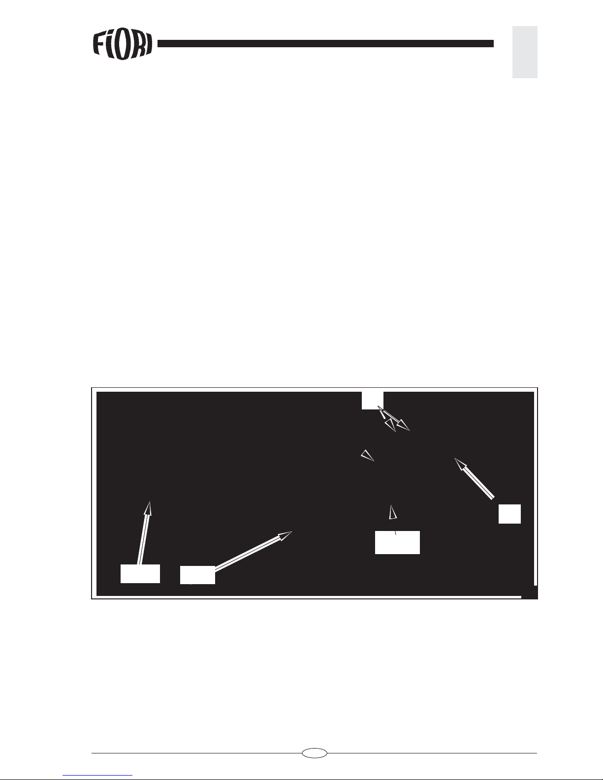
81
REV. 00 02/01/2015
id.:
CBV ADVANCED
DOUBLE ADDITIVE FEEDER
7
REV. 01 24/03/2015
The litre counter with electromagnetic fl ow meter is a device which measures the quantity of liquid fl owing
through it.
Based on an electromagnetic measurement principle (there are no moving mechanical parts inside it), it displays a signal which is proportional to the liquid that fl ows through it.
The display shows a capacity value, calculated based on the data received from the litre counter and on the
value of the constant set by the manufacturer during machine assembly.
CAUTION: This device has been designed for industrial applications. The litre counter MUST NOT,
under any circumstance, be used for measuring the fl ow of hydrocarbons, fl ammable,
explosive or toxic liquids, as provided for by Directive 67/548/EEC dated 27/06/1997.
CAUTION: If additives have different densities or special features, they may distort the litre counter
calculation. Use the additives most commonly used.
7.2
REFERENCES AND DESCRIPTIONS OF THE MAIN DEVICES (fi g. 1).
The parts that control additive feeding and distribution are the following:
A - Litre counter
B - Additive suction pump
1st additive (L2), pump for tank 1
2nd additive (L3), pump for tank 2
C - Pump management device
It is connected to the pump and managed by Fiori Batch Controller. It activates and deactivates the addi-
tive loading to the preset values.
D - Additive tanks
Tank 1
Tank 2
- Liquid pump with rubber membrane.
- Maximum fl ow rate ............................................................................................................. 7.6 l/min at 0.7 bar
- Maximum pressure .............................................................................................................................. 4.2 bar
- DB260 2 tanks, quantity for tank ....................................................................................................... 9.7 litres
- DB460 2 tanks, quantity for tank ........................................................................................................ 15 litres
7.1 TECHNICAL DATA
1
A
B (1°)
C
B (2°)
D (1) D (2)

82
REV. 00 02/01/2015
id.:
CBV ADVANCED
DOUBLE ADDITIVE FEEDER
7
REV. 01 24/03/2015
7.3 FILLING THE ADDITIVE TANKS (fi g. 2)
Before using the additive feeder, check that there is additive in the tanks (1) and (2).
Should the tanks be empty, unscrew the two caps (3) and fi ll them with additive in the desired quantity.
CAUTION: check the effi ciency of the air valve of the two caps (3), and replace them in the event of
malfunctioning.
CAUTION: do not keep the additive liquid in the tanks and in the system for long periods of time, as
this would cause the intake pump membrane B to stiffen.
7.4 SCHEDULED MAINTENANCE TABLE
LITER COUNTER
Description of the symbols used in the table:
= Check and repair = Replace
= Clean = Grease or lubricate
WORKING AREA
EVERY 8
HOURS OR
DAILY
REGULAR MAINTENANCE INTERVALS
EVERY 250
HOURS OR 6
MONTHS
EVERY 500
HOURS OR
12 MONTHS
EVERY 1000
HOURS OR
24 MONTHS
2
3
B
B
1
2

83
REV. 00 02/01/2015
id.:
CBV ADVANCED
DOUBLE ADDITIVE FEEDER
7
REV. 01 24/03/2015
7.5
CHECKING AND MAINTAINING (fi g. 3)
CAUTION: Do not use metal or abrasive objects to clean the duct.
CAUTION: Do not use solvents, diesel or petrol to clean the external parts of the equipment or parts in
its immediate vicinity.
Every six months or in the event of malfunctioning, clean the duct of the litre counter and the relative pipes with
a special non-aggressive detergent for the parts in rubber, nylon, brass, polypropylene and stainless steel.
3
HORIZONTAL INSTALLATION

 Loading...