


ING. O. FIORENTINI S.R.L.
INDUSTRIAL CLEANING MACHINES
SCRUBBER MACHINE
I 42/60 GAS
USER MANUAL

INDEX
1. GENERAL INFORMATION
1.1. Symbols………………………………….…….........................……......………………..
1.2. Notes…….................................................…………...…………..............…...….........
1.3. Manual consulting…………......…………………………....….........………….…………
1.4. Warranty..............................................................…………...…………...….…...........
1.5. Conformity declaration…….........................................…...........………….…...………
2. FEATURES OF THE MACHINE AND TECHNICAL DATA
2.1. Identifying the machine……......…...............................….…………….….……...........
2.2. Description and components.……………...……………………………….…….…........
2.3. Technical data………...................................…........……………………….....…..........
3. SAFETY
3.1. Right use of the machine……....……………....…....……………….....…………........
3.2. Wrong use of the machine .…………………………………………………..…………..
3.3. Suggested equipment……………………………………………………………
3.4. Operator qualify..............……………….......……………...…………...............
3.5. Safety and warning devices ……………..................…...…………............
3.6. Other dangers………………....................................…………..….…....…………........
3.7. Safety signals……………………………………………………………………………….
4. INSTRUCTIONS FOR STARTING AND USE
4.1. Trasport and handling……...................….....................…....………….….….…........
4.2. Storage……………..............................................…………….…………....................
4.3. How to unpack the machine...........................……………………........….....
4.4. How to handle the unpacked machine.….…..........………………………..……..........
4.5. Installation…...............................................................………………..…….............
4.6. Control devices………………………………………………………..
4.6.1. Dashboard…………………………………………………………………………
4.7. Functioning……………………………………………………………………………..
4.7.1. Preparing and starting the machine……………………………………………….
4.7.2. Choosing the right detergent…………………………………………………………..
4.7.3. Driving position regulation…………………………………………………
4.7.4. Rudder bar functioning……………………………………………………………..
4.7.5. Detergent control…………………..……………………………………………………
4.7.6. Squeegee adjustment…………………………………………………………………
4.7.7. Water discharge…………………………………………………………………………
4.7.8. Brushes replacement…………………………………………………………………..
4.7.9. Set the gas cylinders up…………………………………………………………………
4.5.10. Squeegee blades replacement……………………………………………………….
Congratulations for your choice!
FIORENTINI S.r.l. thanking you for the preference to our product, would like to remind
you that FIORENTINI’s S.r.l production covers manufacture and marketing of industrial
cleaning machines and is currently a leading company in this sector.
Our tradition and competence guarantee technical quality of your choice; actually all our
products are being built first quality materials through criteria that can give reliability,
solidity and functionality satisfying every kind of customers. FIORENTINI has recently
obtained the quality system certificate conforming to the requirements of UNI EN ISO
9001:2000.
We wish therefore inviting you to contact us, unhesitatingly, for every kind of request, as
technical or commercial; we’ll be pleased to be at your disposal for any information you
may need.

5. MAINTENANCE
5.1. Periodical maintenance……………..…………..................….....…..…………...........
5.2. Gas engine maintenance………………………………………..………………………..
5.3. Suction motor maintenance………………………………………………..
5.4. Electrict equipment control……………………………………………………………….
5.5. Maintenance register………………………………………………………………….
6. SERVICE
6.1. Service adresses............…………..................……………..................
6.2. Claim report……………………………..…………...………………….…............

GENERAL INFORMATION
I 42/60 GAS
Rev. 000
29/01/10
4/34
1. GENERAL INFORMATION
1.1. SYMBOLS
This symbol is used to get the operator’s attention on procedures or precautions to be
followed in order to avoid damages to users or to the support
This symbol is used to get the operator’s attention on general information.
1.2. AVVERTENZE
MANUAL CONSULTING
This manual deals exhaustively with all arguments that are necessary for an easy and safe use of the
machine as it is recommended by European Directives on product safety.
Therefore we suggest to all authorized operators to read carefully this manual contacting FIORENTINI S.r.l.
for any explanation. The manual has to be used every time the operator forgets a procedure or when new
operators have to be trained.
For publishing reasons, pictures and drawings can look different from the reality but without arising doubts.
Special symbols and bold type and/or sloping get the attention of the reader on remarkable information in
particular for safety.
The revision index is written on the left at the bottom of every page. The list of those pages that have been
updated has to be found at the end of the manual.
1.4. WARRANTY
Warranty conditions are stated as below when not differently specified in the order confirmation.
WARRANTY OBJECT
The machine has been designed and built for a long-lasting use without relevant problems. Anyway, if
problems arise during the warranty period, FIORENTINI S.r.l. is engaged to repair or substitute for free those
parts that are broken or damaged by defective materials, working defects or imperfect assembly.
Warranty is not given for parts whose early breaking or wear and tear are due to:
FIORENTINI S. r. l. is the only owner of this manual.
The reproduction of all or part of the manual or the transmission to third parties with
mechanic or electronic devices are vorbidden without a written manufacturer’s
authorization. This manual is supplied to the customers in one original copy when
differently specified during the order.
This manual is supplied to the customer with the machine and it must be kept with it even when the machine
has to be transferred.
Please, keep the manual in a safe place and for all the machine lifetime. Purchaser is responsible for showing
the manual to qualified people. In case of loss ask for a duplicate to FIORENTINI Co..
FIORENTINI S.r.l. is not responsible for any kind of damages caused by people or things due to the nonobservance of the instructions of this manual.
FIORENTINI reserves the right to add at any time and without notice all the technical and commercial
changes considered useful for the customer. Therefore data and information in this manual
can be
updated.

GENERAL INFORMATION
I 42/60 GAS
Rev.000
29/01/10
5/34
• Non-respect of instructions included in this manual;
• Breaking and/or changes made up without FIORENTINI’s approval;
• Not-use of genuine spare parts;
• Interventions made up by unauthorised personnel;
• Missing maintenance;
• Natural calamities.
FIORENTINI S.r.l., its purchasers and its suppliers have the same warranty for the electric and expendable
materials that are sold by external suppliers.
WARRANTY CONDITIONS
The warranty is granted for 24 months since the machine delivery date. This is a single warranty term and it
cannot be extended.
EXCEPTIONS
Expandable materials like brushes, squeegee blades and materials whose lifetime cannot be predetermined
are not under warranty.
APPLICATION MODALITY
Defective components must be sent back to FIORENTINI S.r.l. in order to establish the anomalies causes
and apply therefore the warranty. Repair and replacement under warranty will be done in FIORENTINI’s
workshop, by third parties or in loco. In case of repair or replacement in loco, energy sources and the use of
particular equipment have to be paid by the customer himself.
INTERVENTION DEMANDS
Intervention demands must be sent to FIORENTINI Service Dpt. only after a careful analysis of the problem
and its causes. Following information have to be given to FIORENTINI’s agent:
• Serial number you get it from the silver label sticked on the machine (§ 2.1.);
• Code and position of the component taken from the spare parts list (§ 7.2.);
• A detailed description of the problem and its causes.
The components considered under warranty are delivered ex works; those ones being substituted belong to
FIORENTINI Co..
GOODS TO BE RETURNED
In case of goods to be returned for warranty replacement, it is necessary to have a written acceptance from
FIORENTINI technical department before sending them.
All defective parts must be carefully packed in order to avoid further damages during transport.
Goods must be shipped ex-warehouse and followed by :
• serial number of the equipment where they were installed on;
• item code of the defective part;
• detailed description of the defect and of the condictions where it happened.
In case of defective electric or electronic goods,
please return them separately from other materials,
in order to help us in dividing dangerous wastegoods
and recicle the (RAEE) as DER 2002/96/CEE LOW.
The machine warranty is no more available in case of the loss of the silver label.
1.5. CONFORMITY DECLARATION
The conformity declaration is released with the machine and the user manual.

GENERAL INFORMATION
I 42/60 GAS
Rev.000
29/01/10
6/34

FEATURES OF THE MACHINE AND TECHNICAL DATA
I 42/60 GAS
Rev.000
29/01/10
7/34
2. FEATURES OF THE MACHINE AND TECHNICAL DATA
2.1. IDENTIFYING THE MACHINE
A silver label is sticked on the protection case of the steering column and clearly shows the data referring to
the “CE” marking.
Ing. O.Fiorentini S.r.l.
MADE
50030 Piancaldoli (FI)
IN ITALY
Mod
I 42 TP/G
S.N.
/
V - rpm
3000
Kg 750 A - kW 14,50
2010
The label has never to be removed and should always be kept readable. In case of
damage t is necessary to ask for a duplicate. The autoscrubber machine cannot be sold
without the label.
2.2. DESCRIPTION AND COMPONENTS
The autoscrubber machine – I 42/60 GAS - has been designed to clean flat surfaces by means of washing
and suction of the washing water.
This machine is equipped with a traction system based on two hydraulic motors. They operate the rear
traction wheels and are fed by a variable delivery pump.
Three hydraulic motors operate the washing brushes. These hydraulic motors are fed by a fixed delivery
pump connected to the variable delivery pump.
The autoscrubber is equipped with two systems: one 12V system and one 36V system. The first system
controls the functioning of the explosion engine, i.e. the hydraulic solenoid valve and the gas system. The
second system is operated by an endothermic engine which starts a dynamo. The dynamo develops a 36V
voltage that controls:
• the lift up or the sink of the squeegee;
• the lift up or the sink of the brushes plate;
• the suction motor;
• the flashing light.
The machine is equipped with two rotating brushes which wash the surface by means of water and
detergent. Whilst the machine is running forward, the back brush (squeegee) picks the water up that is
directly sucked into the recovery tank.
Thanks to the dashboard the operator can control all the machine functions and a series of leds shows to
the operator the battery status or the errors detected by the electronic card.
The operator can control all the main machine functions and in particular:
Start the washing brushes;
Regulate the quantity of water;
Start the suction motor;
Start the lift or the sink of the squeegee;
Choose the forward or back gear;
Start or stop the machine.
PICTURE
N° 2.1

FEATURES OF THE MACHINE AND TECHNICAL DATA
I 42/60 GAS
Rev.000
29/01/10
8/34
The machine frame is made of zinc-plated or stainless steel in order to avoid oxidation which could
compromise the machine reliability.
The main machine components are:
Zinc-plated steel or stainless steel frame;
ABS plastic solution tank;
ABS plastic recovery tank supplied with flexible suction piping system and drainage;
Endothermic engine (Kubota 752);
Squeegee (suction system);
Three rotating brushes;
Water recovery system;
one idle wheel;
two traction wheels operated by two hydraulic motors;
steering wheel;
driving seat.
FIORENTINI Co., taking the new CE safety rules into consideration, manufactures the machine following the
CE directives about safety and health. The materials high quality, the high technology and FIORENTINI’s
experience guarantee the performance and the reliability of this machine .
Each machine is tested during the manufacturing process and the final check is done before the machine is
shipped out.

FEATURES OF THE MACHINE AND TECHNICAL DATA
I 42/60 GAS
Rev.000
29/01/10
9/34
2.3. TECHNICAL DATA
The above mentioned characteristics are not binding for the manufacturer; they can be
changed without any notice . ING.O.FIORENTINI Co. is always at disposal for any
information (par.7.1.).
MEASUREMENT UNITS CONVERSION
Lenght
1 inch = 1” = 25,4 mm
Power
1 kW = 1,36 CV = 1,34 BHP
Temperature
T (K) = t (°C) + 273 / t (°F) = 1,8 t (°C) + 32
Pressure
1 bar =100 kPa = 14,5 psi
DIMENSIONS
I 42
I 60
LENGHT
2150 mm
2230 mm
WITDH 1250 mm 1550 mm
HEIGHT 1500 mm 1500 mm
WASHING BRUSHES 3 3
TRACTION hydraulic hydraulic
WASHING BRUSHES DIMENSIONS Ø 380 mm Ø 460 mm
CLEANED AREA 1150 mm 1450 mm
SQUEEGEE WIDTH 1470 mm 1650 mm
SOLUTION TANK CAPACITY 340 mm 340 mm
RECOVERY TANK CAPACITY 340 mm 340 mm
BRUSHES PRESSURE 0/120 Kg 0/120 Kg
ENGINES FEATURES
ENGINE Kubota 752 Kubota 752
CYLINDERS 2 2
DISPLACEMENT 750 cc 750 cc
POWER 19 cv 19 cv
BRUSHES HYDRAULIC ENGINE OR 80 OR 80
TRACTION HYDRAULIC ENGINE OP 160 OP 160
VARIABLE DELIVERY PUMP 14 l 14 l
FIXED DELIVERY PUMP 4.2 l 4.2 l
SUCTION ENGINES 2x36V 800W 2x36V 800W
FUNCTIONS
DRIVING SYSTEM On drive On drive
U-TURN LANE 2900 mm 3020 mm
BRUSHES LIFT UP SYSTEM hydraulic hydraulic
SQUEEGEE LIFT UP SYSTEM hydraulic hydraulic
SERVICE BRAKE mechanical mechanical
PARKING BRAKE mechanical mechanical
PERFORMANCE
FORWARD SPEED 0/12 km/h 0/12 km/h
HIGHEST SLOPE 13 % 13 %
CLEANING 13800 m²/h 17400 m²/h
ENVIRONMENTAL FEATURES
NOISES FOR THE OPERATOR 91 dB 91dB

SAFETY
I 42/60 GAS
Rev.000
29/01/10
10/34
3. SAFETY
3.1. RIGHT USE OF THE MACHINE
This machine is a scrubbing machine and it has been designed and built to clean in
an industrial place. It can work on flat surfaces or on surfaces with a slope not
higher than 13% and with a speed not higher than 1 km/h for U-turn.
3.2. WRONG USE OF THE MACHINE
The machine cannot be driven by non-authorized personnel;
The machine cannot wash sloping surfaces whose gradient is higher than 13%
or surfaces with holes;
The machine cannot be used to wash sloping surfaces;
The machine cannot reverse with a speed higher than 1 km/h on surfaces whose
gradient is higher than 5%;
The machine cannot be used in places with dangerous substances and in
particular with explosive atmospheres or with a bad microclimate;
The machine cannot clean surfaces with inflammable products;
The machine cannot be used as a means of transport for people or other means
of transport;
The machine protection devices cannot be modified or tampered;
Batteries must be recharged in a fanned room;
The operator have always to respect safety rules;
The operator cannot use equipments or devices that can create problems to the
machine working;
The machine components cannot be modified without FIORENTINI’s
authorization;
The operator cannot use acids that can damage the machine;
The operator has always to respect the rules written in the user manual.
Please read carefully and do not cover the labels sticked on the machine. FIORENTINI
S.r.l. is not responsible for a wrong use of the machine (see § 3.2.)
3.3. SUGGESTED EQUIPMENT
In order to use the machine in a proper way, we suggest to use the FIORENTINI’s equipment and original
spare parts.
FIORENTINI S.r.l. Technical Dpt. is always at your disposal to design components or parts for a particular
use of machine as requested by the customer.

SAFETY
I 42/60 GAS
Rev.000
29/01/10
11/34
3.4. OPERATOR’S QUALIFY
The scheme below sumarizes the operator qualify requested for each kind of operation.
OPERATION
OPERATOR’S QUALIFY
Driving/control of the machine
Trained operator
Installation/ disinstallation Fiorentini technician
Mechanical parts maintenance
Fiorentini technician
Electric parts maintenance
Fiorentini technician
Cleaning maintenance
Trained operator
Dismantling and demolition
Fiorentini technician
FIORENTINI S.r.l. suggest to train the operator before using the machine. The operator also must be trained
about safety rules and carefully read this manual.
FIORENTINI S.r.l. is not responsible for any possible damage to people and/or things caused by
the non-observance of the instructions dealt within this manual.
3.5. SAFETY AND WARNING DEVICES
• It is absolutely forbidden to tamper or disconnect safety and warning devices while
the machine is working;
• It is important to check periodically safety and warning devices (see § 5.1.).
Side brushes protection
I 42/60 GAS is equipped with three nylon brushes which rotate while the
machine in on duty.
La macchina I 42/60 GAS e dotata di tre spazzole, con setole in nylon che
sono in rotazione durante il normale utilizzo. The machine cannot reach
dangerous areas thanks to fixed plastic protections set up on each brush. The
brush protection can be only willingly removed.
Protection for hot parts
I 42/60 GAS is equipped with a steel rear case to protect hot parts of the
engine and the engine itself.
This case can only willingly be opened. Make sure that it is well closed.
Warning devices
I 42/60 GAS is equipped with several warning devices:
One acustic warning device like a claxon. It has to warn people who are
near the machine while its operating;
one flashing yellow light to signal the machine operating.

SAFETY
I 42/60 GAS
Rev.000
29/01/10
12/34
3.7. OTHER DANGERS
FIORENTINI S.r.l. analyzes since the machine design all dangers that can occur while the machine is
operating in order to prevent or at least low the operator’s accident. Thanks to a series of signals on the
machine the operator can avoid many risks that can occur during the machine operating.
CRUSHING
This kind of danger can occur:
• during the front brushes replacement;
• during the check up of the coal brushes of the suction engine;
• during the squeegee regulation.
Whilst replacing the brushes and regulating the squeegee, the ignition key must be kept away from
the dashboard in order to avoid the casual starting of the machine.
Whilst replacing the coal brushes of the suction engine, the operator must pay attention that any
parts of his/her body is between the machine and the cylinder support.
Special labels sticked on the cases of the brushes or on the recovery tank prevent dangers
to the operator (see § 3.7.).
BURNING DANGER
This kind of danger can occur:
• during the check up of the oil engine.
Whilst changing or checking the oil engine make sure that the machine has been switched off a few
minutes ago before opening the rear case, in order to avoid to touch hot parts of the machine.
Special labels sticked on the case of the steering column prevent dangers to the operator
(see § 3.7.).
TURNOVER
This kind of danger can occur:
• during the normal operating of the machine when you exceed sloping limits as specified in
the manual and you use the machine to clean disconnected surfaces or with holes and high
depressions (photo 3.2)
Do not use the machine to wash sloping surfaces higher than 10% or surfaces with
holes or depressions which might compromise the stability of the machine.
FIORENTINI is not responsible for accidents occurred to people or things provoked by a
wrong use of the machine, i.e. using the machine on surfaces which can compromise its
stability.
The purchaser must stick proper labels on the machine to show to the operator the right use
of the scrubber.

SAFETY
I 42/60 GAS
Rev.000
29/01/10
13/34
3.8. SAFETY SIGNALS
DANGERS
Dangers’ signals are triangular with black
pictures on a yellow background
PROHIBITIONS
Prohibitions’ signals are round with black
pictures and a red stripe
The purchaser must replace danger signals on the machine if they are deteriorated.
It is absolutely forbidden to remove or temper danger signals.
What is it?
Crushing danger: it can be due to parts in movement of the machine.
What to do
During the installation or the maintenance make sure that the ignition
key is not in the dashboard before removing the mobile protections.
What is it? This signal forbids to remove the protection of pieces in movement.
What to do
During the installation or the maintenance make sure that the ignition
key is not in the dashboard before removing the mobile protections.
While the machine is operating make sure that all covers are well
fixed.

SAFETY
I 42/60 GAS
Rev.000
29/01/10
14/34
The purchaser must replace danger signals on the machine if they are deteriorated.
It is absolutely forbidden to remove or temper danger signals.
What is it?
Squashing danger: it can occur while closing the rear case or it can
be due to the cooling fan.
What to do
Make sure that the ignition key is not in the dashboard during the
maintenance or the check up of the machine.
What is it?
This signal forbids to remove the protections of hot parts of the
machine while the machine is working.
What to do
Make sure that the machine has been switched off a few minutes ago
and that the ignition key is not in the dashboard.

SAFETY
I 42/60 GAS
Rev.000
29/01/10
15/34
The purchaser must replace danger signals on the machine if they are deteriorated.
It is absolutely forbidden to remove or temper danger signals.
What is it?
Squashing danger: it can occur while changing the coal brushes of the
suction engine or while checking the recovery tank up.
What to do
Make sure that the ignition key is not in the dashboard and that the
cylinder support is completely turned over.
What is it?
The signal forbids to drive the machine on slopes whose gradient is
higher than 13%.
What to do
Make sure that the slope is not higher than 10%. On the contrary, do
not drive the machine on slopes whose gradient is higher than 10% in
order to avoid that the machine turns over.

INSTRUCTIONS FOR STARTING AND USE THE MACHINE
I 42/60 GAS
Rev.000
29/01/10
16/34
4. INSTRUCTIONS FOR STARTING AND USE THE MACHINE
4.1. TRANSPORT AND HANDLING
The machine is delivered to the purchaser in a proper package (see picture 4.1 below where are indicated all
the I42 machine dimensions). A black arrow on the package indicates the barycentre. This arrow must be in
the middle of the elevator or transpallet forks. The package must be carefully handled. Do not place one
package on another one. If agreed with the purchaser, the machine can be delivered without package,
placed on a pallet and fixed by means of straps.
The purchaser must make sure that the machine has not been damaged during the
transport and that all papers are on the machine. Otherwise, the purchaser must
immediately contact FIORENTINI in order to sort out the problem.
The purchaser is responsible for the transport of the machine if not differently agreed with
FIORENTINI.
The machine must be handled with proper devices as stated in the scheme below. Please, make sure that
the black arrow on the package is always in the middle of the elevator forks or the sling bands.
PACKAGE
HANDLING EQUIPMENT PICTURE
Paperboard or plywood box on
a pallet
Fork elevator Nr. 4.2.
None
Fork elevator or crane truck with a two-band-sling and
equalizer
Nr. 4.3.
The bands used to lift the machine up must have the same loading capacity as the
machine load. Handling operations must be done without causing a loss of stability
of the machine. Otherwise, the machine can be damaged or the operator can de in
danger.
FIORENTINI suggest to use authorized personnel (see § 2.3.) to handle the machine.
PICTURE 4.1

INSTRUCTIONS FOR STARTING AND USE THE MACHINE
I 42/60 GAS
Rev.000
29/01/10
17/34
LOADING SYSTEM
4.2. STORAGE
The machine must be stored in a closed and dry place if not immediately installed in order to keep every part
safe.
Relative humidity must be lower than 80% and the storage temperature must be between 3°C ≤ t ≤ + 45 °C.
4.3. HOW TO UNPACK THE MACHINE
Cut the straps paying attention to the back spring;
Remove the staples that join the paperboard and the pallet;
If the package is mad of plywood, please remove the staples from each side;
Cut the straps that fix the machine;
Lay the machine on the floor.
4.4 HOW TO HANDLE THE UNPACKED MACHINE
Check the machine and install the batteries if not already installed;
For a brief transport of the machine, please disconnect the batteries cables and remove brushes and
squeegee; for a longer transport, please use the original package of the machine.
PICTURE N. 4.2 PICTURE N. 4.3

INSTRUCTIONS FOR STARTING AND USE THE MACHINE
I 42/60 GAS
Rev.000
29/01/10
18/34
4.5. INSTALLATION
The autoscrubber ICM38GAS can be started only when you are completely sure that all the components and
devices of the machine are efficient.This is why, well trained FIORENTINI technicians do a strict control while
producing the machine and an accurate final test. Anyway, FIORENTINI suggests to do another test before
starting the machine. Please see the scheme below.
Result
Test
√ X
Hydraulic oil level
Engine oil level
Engine cooling water level
Wheels brake
Pilot lights functioning
If the result of the test is positive, the machine can be started. On the contrary, please contact immediately FIORENTINI
service.
The test above must be periodically done in order to keep the machine always efficient.
The machine must be started by authorized personnel.
4.6. CONTROL DEVICES
4.6.1. DASHBOARD
The dashboard is made of a series of switches that activates or disactivates all the machine functions. The
function of each switch is shown by a picture. Picture 4.6. shows the dashboard of the machine and the
switches function is explained in the scheme of the following page.

INSTRUCTIONS FOR STARTING AND USE THE MACHINE
I 42/60 GAS
Rev.000
29/01/10
19/34
1 Blinker fuse 14 Gas oil level indicator
2 Light fuse 15 Solution regulation lever
3 Oil cooler fan fuse 16 Horn
4 Electro valve fuse 17 Accessory (sweeping group)
5 Controls alimentation fuse 18 Blinking switch
6 Direction signals and stop fuse 19 Light switch
7 Empty 20 Squeegee up and down
8 Empty 21 Vacuum motor switch
9 Empty 22 Brush up/down and on/off
10 Empty 23 Diesel motor temperature indicator
11 Empty 24 Key switch
12 Hour counter manometer 25 Igniter plug switch
13 Oil pressure indicator 26 Battery charger indicator
PICTURE N. 4.6

INSTRUCTIONS FOR STARTING AND USE THE MACHINE
I 42/60 GAS
Rev.000
29/01/10
20/34
4.7. FUNCTIONING
The operator, thanks to his/her experience, has to choose the right type of brush and detergent for the
surfaces that has to be washed and to decide if the floor needs a second washing.
Follow these instructions for a correct washing:
1. press the brushes motor switch (nr. 1);
2. press the solution solenoid valve switch (nr. 4);
3. press the suction switch (nr. 2).
By means of the accelerator pedal the washing brushes and the suction motor are activated. On the
contrary, both the washing brushes and the suction motor are disactivated after a few seconds if the operator
leaves this pedal. Before the surface is completely dry, the operator must switch the solution solenoid valve
off because this is not activated/disactivated by the accelerator pedal.
The operator has to do a second washing if the surface is particularly dirty:
1. wash the surface with the squeegee up and the brushes down;
2. activate the brushes;
3. press the solution solenoid valve switch;
4. leave the solution on the surface to dissolve the dirt;
5. do a second washing with brushes and squeegee down, the suction activated and the solution solenoid
valve open.
Before any operation, make sure that all protections are well fixed.
4.7.1 PREPARING AND STARTING THE MACHINE
the operator must fill water lifting the recovery tank up and turning the cap (see detail nr. 1 in picture nr. 4.7.).
Now the operator can seat on the machine, start it and wash the surface.
PICTURE N. 4.7
1
INSTRUCTIONS FOR STARTING AND USE THE MACHINE
I 42/60 GAS
Rev.000
29/01/10
21/34
4.7.2 CHOOSING THE RIGHT DETERGENT
Choosing the right detergent is very important for a perfect cleaning. A too strong detergent could damage
the surface. A good quality detrgent has to produce little foam. Alternatevely, the operator can add an
antifoaming additive or 50 cc of wine vinaigre in the recovery tank in order to avoid the suction motor
damage.
Make sure that the detergent is suitable for the dirty surface. FIORENTINI S.r.l. is not
responsible for damages provoked by too aggressive detergents.
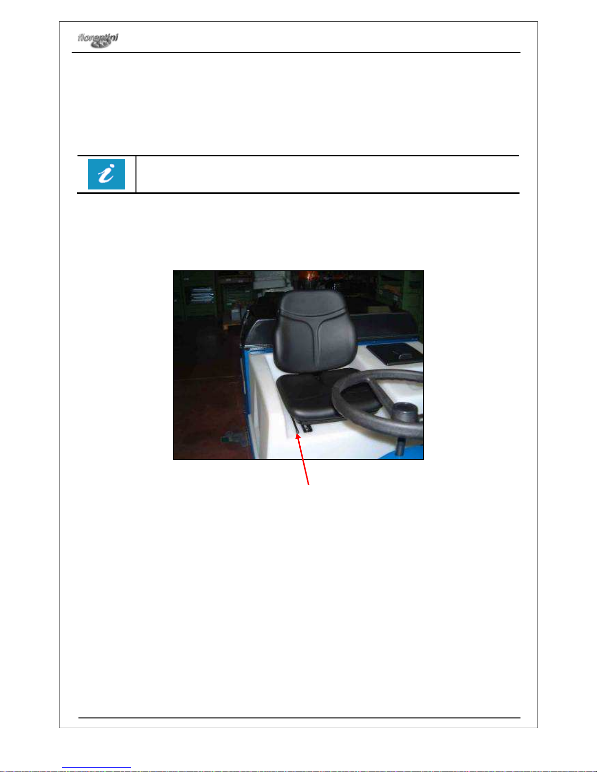
4.7.3 DRIVING POSITION REGULATION
By means of the lever (see detail nr. 1 in picture nr. 4.8.) for the steering column regulation, the operator can
pull backward or push onward the steering wheel in order to have a driving position which fits his/her body.
4.7.4 RUDDER BAR FUNCTIONING
The rudder bar of this scrubber machine is composed by:
Accelerator pedal (see detail nr. 3 in picture nr. 4.9.): the machine moves forward by means of the
right pedal and backwards by means of the left pedal.
Service brake (see details nr. 1 and 2 in picture nr. 4.9.): it has to slow and stop the machine. If the
operator wants to set the service brake on, he/she has to press the service brake pedal. If he/she
wants to release the service brake, he/she has to press both the brake pedal and the release pedal
and the release knob (see detail nr. 2 in picture nr. 4.9.).
Accelerator lever (see detail nr. 4 in the picture nr. 4.9.).
PICTURE N. 4.8
1

INSTRUCTIONS FOR STARTING AND USE THE MACHINE
I 42/60 GAS
Rev.000
29/01/10
22/34
4.7.5 DETERGENT CONTROL
During the washing the operator can control the detergent quantity by means of a cock, which is at the
bottom of the machine on the left inside the protection rubber (see detail nr. 1 in picture 4.10.).
PICTURE N. 4.10
PICTURE N. 4.9
4 2 1 3
1

INSTRUCTIONS FOR STARTING AND USE THE MACHINE
I 42/60 GAS
Rev.000
29/01/10
23/34
4.7.6 SQUEEGEE ADJUSTMENT
The squeegee must be perfectly adjusted to get a perfect floor drying. ICM 42 is equipped with a V-shaped
squeegee, as shown in . This type of squeegee performs very well in collecting water from the floor to the
suction hose, but is particularly sensitive to the parallelism to the floor. Therefore, adjust first its angular
position through the screws so that its rubber blades get the same slanting on the floor along its entire width.
If blades are more pressed at their ends than in their centers, unscrew the upper screws and screw the
lower ones , then tighten the lock nuts. If, on the contrary, blades are more pressed at their centers than in
their ends, perform the opposite operation. After having reached the right angular position, adjust the
pressure. Turn the ring nut and tighten it to increase pressure to the floor, or loosen to decrease it. The right
pressure is got when the edge of the rear blade touches the floor with a slanting of approx. 60°-45° r eferring
to the floor. If the pressure is too high, the rear blade will touch the floor with its side surface, and not with its
edge. If the pressure is too low, the edge doesn’t work well and lets some water on the floor, particularly on
an uneven floor. Of course the optimal adjustment is confirmed by very good results of the drying operation,
and the operator’s experience will contribute to enhance such good results. Note that often drying is
negatively affected by a wrong suction operation. If the suction hose doesn’t work well, drying will continue to
be bad, even with all adjustments attempts. In this case:
a) accurately clean the suction hoses, their inlets and filters and the squeegee itself
b) check the vacuum motors operation
c) confirm that all inspection openings of the tank are closed.
Make sure that the two wheels of the squeegee are well regulated in order to keeps both
its blades parallel to the floor.

INSTRUCTIONS FOR STARTING AND USE THE MACHINE
I 42/60 GAS
Rev.000
29/01/10
24/34
4.7.7 WATER DISCHARGE
This scrubber machine is equipped with two pipes for water discharge (picture 4.15.):
A pipe for the recovery tank discharge (see detail nr. 1 in picture nr. 4.15.);
A suction pipe (see detail nr. 1 in picture nr. 4.15.);
If you need to discharge water from the tanks, you have to place the machine on a dump well, release the
pipe of the tank and open the rubber cap at the end of the pipe itself.
PICTURE N. 4.15
1
2

INSTRUCTIONS FOR STARTING AND USE THE MACHINE
I 42/60 GAS
Rev.000
29/01/10
25/34
4.7.8 BRUSHES REPLACEMENT
The operator has to follow the instructions below to replace the brushes:
Take the ignition key away from the dashboard in order to avoid a casual starting of the machine;
Right side brush replacement: remove the case by means of the lever (see detail nr. 1 in picture nr.
4.16) and translate it outside. Translate counterclockwise the right brush and remove it;
Left side brush replacement: follow the same istructions as for right side brush replacement (see
detail 2 in picture 4.18). Translate clockwise the left brush and remove it;
To set a new brush up (see detail 3 in picture 4.17): put the coupler pins under the brush support
slots, pull the brush up and translate it (clockwise for the right brush and counterclockwise for the left
one);
Set again the brushes cases up and fix them by means of the lever.
Make sure that both cases of the lateral brushes are well fixed before starting the machine.
1
3
PICTURE N. 4.17
2

INSTRUCTIONS FOR STARTING AND USE THE MACHINE
I 42/60 GAS
Rev.000
29/01/10
26/34
4.7.9 SET THE GAS CYLINDER UP
Please follow the instructions below to set the gas cylinder up:
Place the gas cylinder on its support (see detail 1 in picture 4.18) and fix it by means of belts (see
picture 4.18);
Insert the pipe into the cylinder and tighten it with a clamp. Insert the other end of the pipe into the
machine through the hole (see detail nr. 2 in picture 4.18);
Insert the rubber pipe joined to the copper pipe into the machine.
Before starting the machine again make sure that the gas cylinder has been perfectly set up
and that there are no leaks.
PICTURE N. 4.18
2
1

INSTRUCTIONS FOR STARTING AND USE THE MACHINE
I 42/60 GAS
Rev.000
29/01/10
27/34
4.7.10 SQUEEGEE BLADES REPLACEMENT
The squeegee blades should be replaced when the contact edge becomes worn; the perfection of the edge
is essential for a perfect drying. To replace the blades, the squeegee should be removed from the machine.
To do that, lift the squeegee support in UP position, then remove the suction pipe from the squeegee ,
partially unscrew the screws . At this point, remove the squeegee from the machine and place it on a desk.
Now, remove the screws both on the front part and on the rear part of the squeegee, the steel straps , and
the three worn rubber blades as well. Perform the inverse procedure and assemble the new blades, then
adjust the squeegee.
PICTURE N. 4.19

MAINTENANCE
I42/60 GAS
Rev.000
29/01/10
28/34
5. MAINTENANCE
5.1. PERIODICAL MAINTENANCE
A periodical maintenance is very important.
Please fill in the format you find below all the interventions done on the machine.
OPERATION INTERVENTION HOW OFTEN
Clean the recovery tank and the oil filter of the
suction motor
•
Do not use corrosive substances.
•
Do not use bolts of water.
Daily
Check the suction pipes and the squeegee
Check the oil motor
Check the coolant
Every week
Check the rubber suction blades of the
squeegee
Check the air filter
Every 15 days
Check the filter of the clean water tank Every month
Check and regulate the breaking system
Replace the motor oil filter
Check the belts tension
Every three months
Check the connection of the battery cables
Check the water battery level
Replace the air filter
Replace the hydraulic oil filter
Every six months
Cleaning – Controls Replacement
Check the coal brushes of each motor
Check the pipes of the hydraulic system
Check the electric system
Check the safety devices
Every year
• Every kind of control, cleaning and replacement must be done when the machine is off.
•
Trained personnel only can service the machine and especially electric and electromechanical
parts by means of suitable tools and equipments.
•
Make reference to FIORENTINI S.r.l. only for service and spare parts (§ 7.1. and § 7.2.).

MAINTENANCE
I42/60 GAS
Rev.000
29/01/10
29/34
5.2
GAS ENGINE MAINTENANCE
For any kind of intervention on the engine please follow the instructions of the engine
logbook (Kubota 752) delivered with the machine.
For the maintenance, check what follows:
• Oil lever every 50 working hours, replace it every 150 hours
• Level cooling fluid every 50 hours
• Replace air filter it every 100 hours
• Replace diesel filter every 250 hours
• Replace motor oil filter every 300 hours
• Replace hydraulic oil filter every 750 hours
• Check aternting belt tension every 250 hours
• Injection calibration and cleaning every 1000 hours
• Adjusting rocker lever clearance every 1000 hours
5.3 SUCTION MOTOR MAINTENANCE
The vacuum motors must be checked and cleaned. The brushes should be checked all six months and
replaced, if necessary. After removing the key from the dashboard, remove the motor cover located on the
rear part of the machine. To release the motors (fig.), unhook the hooks (fig.) and detach the plug (fig.). In
this way, it is possible to extract the motors and release the sponge filter under the motors that can be
extracted, cleaned and replaced. Check the suction fan from the hole located in the front part of the vacuum
motor. By a visual check, the fan should appear undamaged and well-cleaned. To check the brushes, first of
all remove the plastic cap, then unscrew the screws (fig.) and remove the two plastic supports of the
brushes. Once checked and replaced (if necessary), the brushes can be easily remounted, by reassemblying
all elements until the initial situation has been reached.

MAINTENANCE
I42/60 GAS
Rev.000
29/01/10
30/34
5.4 ELECTRIC EQUIPMENT CONTROL
It is very important to check the electric system up every two years. Disconnected cables or burnt cables
must be immediately replaced.
Interventions on the electric system must be carried out by a trained technician.
Every kind of intervention not explained in the operator manual must be carried out by
FIORENTINIs technicians.

MAINTENANCE
I42/60 GAS
Rev.000
29/01/10
31/34
5.5. MAINTENANCE REGISTER
DATE
OPERATOR INTERVENTION SIGNATURE

SERVICE
I42/60 GAS
Rev.000
29/01/10
32/34
6. SERVICE
6.1. SERVICE ADDRESSES
Do not hesitate to contact FIORENTINI S.r.l. service for any kind of information or request.
Most of the technical problems can be sorted out with short intervention. This is why FIORENTINI S.r.l.
suggest to read carefully this manual before using the machine. On the contrary, if the customer needs a
FIORENTINI’S technician, please inform us about the problem in order to sort it out with the right material.
6.2 CLAIM REPORT
Please, fill in the format below if the machine shows particular problems.

SERVICE
I42/60 GAS
Rev.000
29/01/10
33/34
Operator:
Company:
Operator’s name:
Role:
Date:
Signature:
Machine description:
Machine:
CUCCIOLO
Type:
Purchase date:
S.N.:
Warranty:
YES
NO
Work hours:
Where does the machine
normally work?
Fault:
Code of the
defected
component:
Description:
Fault: Fault short description:
Mechanical component
Wrong functioning
Electric system
Engine
Missing component
Estremely noisy
Water leak
Other
Customer’s suggestion:

SERVICE
I42/60 GAS
Rev.000
29/01/10
34/34
Mat. n.
Serial no. _____________________
Nr. de serie
Data di spedizione
Date of shipment _____________________
Date de spedition
ING. O. FIORENTINI s.r.l.
“T
HE BEST IN FLOOR MACHINES
”
FILIALI:
20132 MILANO – Fax. 02/2592779
Via Palmanova 211/a – Tel. 02/27207783 - 2564810
00155 ROMA – Fax. 06/22754075
Via Carlo Carrà 13 – Tel. 06/22754040-2275060
STABILIMENTO:
50030 PIANCALDOLI (FI) – Fax. 055/817144
Loc. Rombola – Tel. 055/8173610
Distributed by:
 Loading...