

Page 1
ING. O. FIORENTINI s.r.l.
HS 2000
Spare parts
Operating instructions and
maintenance
Page 2

Page 3

THIS MANUAL CONTAINS VITAL INFORMATION FOR THE SAFE USE AND EFFICIENT
OPERATION OF THIS MACHINE. CAREFULLY READ THIS OPERATOR’S MANUAL BEFORE
STARTING THE MACHINE, AND RETAIN FOR FUTURE REFERENCE. INSTRUCT ALL
OPERATORS TO READ THIS MANUAL. FAILURE TO ADHERE TO THE INSTRUCTIONS
COULD RESULT IN SERIOUS BODILY ANJURI OR PROPERTY DAMAGE.
PRESCRIBED USAGE
This machine is designed for the professional cleaning according to these operating instructions.
For the safe operation of this machine, and for the safety of the operator observe the following instructions:
1) Do not use this machine in an explosive atmosphere such as gas vapor etc. .
2) Do not operate this machine unless it is completely assembled.
3) Do not leave this machine plugged into the power source while unattended.
4) The Floor Maintainer is designed to be used with detergent and water .They should never be
used with flammable materials such as : gasoline, kerosene, etc. .
5) Do not clean this machine with a high pressure cleaner by water but use only air pressure
cleaner.
GENERAL SAFETY INSTRUCTION
This machine is designed and constructed according to the present state of the art and recognised technical safety standards. It is fitted with protective devices, following safety European
standard rules. Dangers can occur in spite of this, in particular in the case of maloperation or
non-compliance with the specifications and information in the operating instructions.
All our equipements are covered by international assurances against risks.
1) Sources of danger.
Electrical voltage / Electric current
Warning: Danger
Contact with voltage or current carryng parts carries the risk of electric shock which can result in
serious injury or even death. Never touch damaged cables. Always switch off and disconnect the
power supply before carrying out any work on the machine. Replace faulty cables immediately.
2) Improper usage.
Any usage of the machine for a purpose not covered under the “Prescribed usage” or contractually agreed purpose is not permissible. The use of the machine in an unserviceable condiction
or not in compliance with the following prescription is prohibited:
- Protective devices must not be removed or bypassed.
- Conversions and modification to the machine are not permitted.
- Defective supply cables are only to be replaced by original FIORENTINI cables.
- Coupling elements between mains supply or detachable extension cable must be at least
splashproof.
- The machine is to be fitted with a type H circuit breaker for rated current of 15A.
3) Organisational points.
It is the responsibility of the operator to ensure that:
- The machine is used only by personnel who have been instructed in its handling and authorised to use it.
- The recognised occupational safety regulations are observed.
- Any further national or internal company regulations are observed.
- All users are acquainted with the safety regulations and trained in the use of the specific machine.
- All users have read and understood the operatin instructions.
- Responsabilities for the operation, maintenance and repair of the machine are clearly assigned
and observed.
- Faults and damage are immediately notified to the Service Agent of FIORENTINI.
4) Emergencies.
In the case of an emergency:
- Pull out the mains connector plug.
- Immediately apply recognised first-aid measures.
After incidents, do not resume operation with the machine until it has been inspected by FIORENTINI authorized technical.
5) Operating for the first time.
Page 4

Delivery, instruction on safety rules, handling and maintenance as well as operation for the first
time must be carried following the specification of this instruction book. The operator is responsible for instructing the users.
FURTHER SAFETY INSTRUCTIONS CONCERNING OPERATING AND MAINTENANCE ARE
DETAILED IN THE RELEVANT SECTIONS AND MUST BE COMPLIED WITH!
IMPORTANT NOTES
Before starting to use the machine please observe the following points:
- If you should discover any damage when unpacking the machine please inform your sale agency.
- The supply voltage must be the same as that shown on the nameplate.
FOR ALL GROUNDED APPLIANCES
This appliance should be grounded while in use to protect the operator from elettric shock. The
appliance is equiped with an approval three-conductor european cord and three-prog grounding
type plug to fit the proper grounding type receptacle. The green (or green and yellow ) conductor
in the cord is the grounding wire. Never connect the green (or green and yellow) wire to a live
terminal.
OPERATION OF HIGH SPEED FLOOR MACHINES
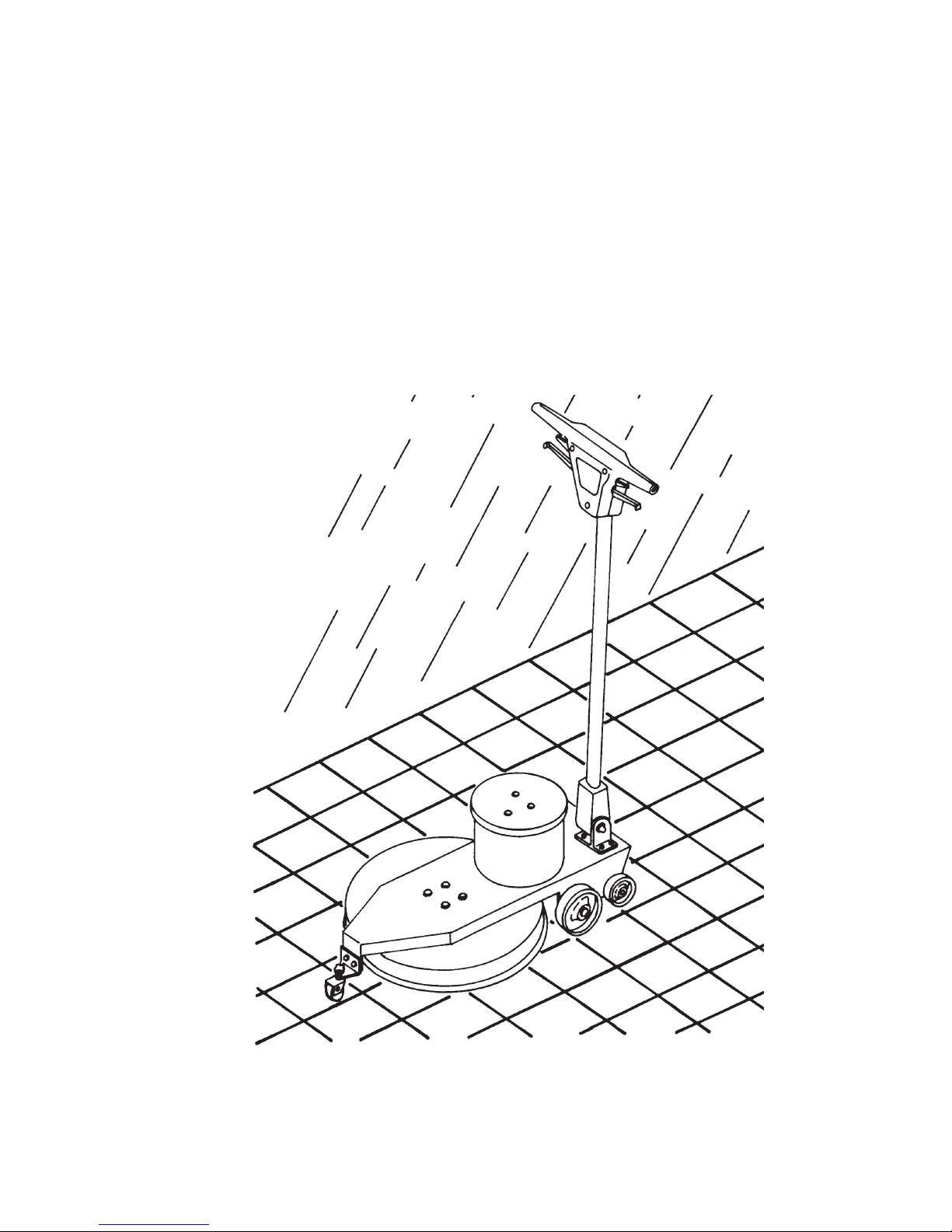
Fiorentini high speed floor machines are designed to be used with a forward and backward movement. It will not swing side to side as with standard, low speed machines. The front of the machine should be lifted for turning, transporting and storage of the machine. Damage to the pad
and pad driver can result if pushed, pulled or stored with the weight of machine on the pad while
it is not in operation. Do not apply pressure or weight to the front of the machine while in operation. This causes an excessive load on the motor and will shorten the life of the motor. Model
1100 and 1500 are balanced to provide superior performance when used with the proper pad
and high quality floor finishes. The Model 2000 comes equipped with a front caster to stabilize
the machine at its 2000 rpm operating speed. This caster is adjustable to achieve proper pad
pressure. Pleas refer to the pad installation procedures regarding adjustement of this caster. The
machine was pre-adjusted at the factory using a 25mm thick pad. Fiorentini high speed floor
machines come equipped with a 15m heavy gauge power cord. We do not recommend the use
of extension cords with these floor machines. Damage to the motor can result due to a voltage
drop when inadequate extension cords are used.
WARNING: NEVER TURN ON MACHINE WHEN HANDLE IS IN UPRIGHT VERTICAL
POSITION BECAUSE THE MACHINE IS SUPPLYED OF SAFETY MICRO-SWITCH. THE “ON”
AND “OFF” MASTER SWITCH IS OPERATED BY MEANS OF LEVERS IMMEDIATELY
UNDER HANDLE GRIPS. WHEN TRANSPORTING OR STORING MACHINE, RAISE HANDLE
TO VERTICAL POSITION.
PRESTART-UP CHECKS
1) Check pad and pad driver; both must be secure and properly aligned.
2) Check handle assembly and camlock lever. Loose bolts should be tightened to avoid damage
to attachment points.
3) Check power cable, strain relief and cord plugs for frayed or damaged insulation.
4) Plug power cord into outlet.
5) Adjust handle height to desired level and with the
6) The machine can be operated wit either the right or left levers located below the handle bars.
Squeeze the lever toward the handle bar to start the machine.
USE CAUTION
DO NOT hold the machine in one spot for more than one or two second. This is a high speed
machine and can damage a hard surface floor very quickly leaving a permanent burn mark. If
you must stop, release the trigger lever to stop the machine.
AVOID any protruding objects such as bolts, mouldings, conduit pipes, etc. Even the slightest
contact can damage the pad and pad driver.
PAD DRIVER AND PAD SELECTION
These HIGH SPEED MACHINES come equipped with a balanced high speed pad driver with a
locking pad holder. This style pad driver and the locking pad holder must always be used. An unbalanced pad driver will create vibration.
Page 5
Vibrations can damage the machine and is unsafe to operate. If the locking pad holder is not
used, the pad will be thrown out from under the pad driver.
Proper pad selection is important to achieve the desired performance of the machine and desired floor finish. We recommended a 25 mm. thick pad. There are many types and grades of
pads available. Poor quality pads are often uneven in density causing thick and thin spots which
cause vibrations and poor finish. Avoid using seconds or rejected pads. Pad installation is a simple procedure.
Lock the handle in the full upright position. Disconnect the power at the outlet (unplug cord). Tilt
the machine back fully, allowing it to rest on the handle block and wheels. The pad locking mechanism is a yellow plastic piece found at the center of the driver. The center section and lock
plate are removed by turning counter-clockwise as indicated by the arrows on the lock ring. Fully
remove the lock nut from the hub. Lift the old pad off and turn over or discard as needed. Place
new pad into pad driver making certain it is centered to avoid erratic operation. Re-install the center lock plate and ring and hand tighten. The pad driver and center ring will hold the pad securely while in operation.
FRONT CASTER (Model HS 2000)
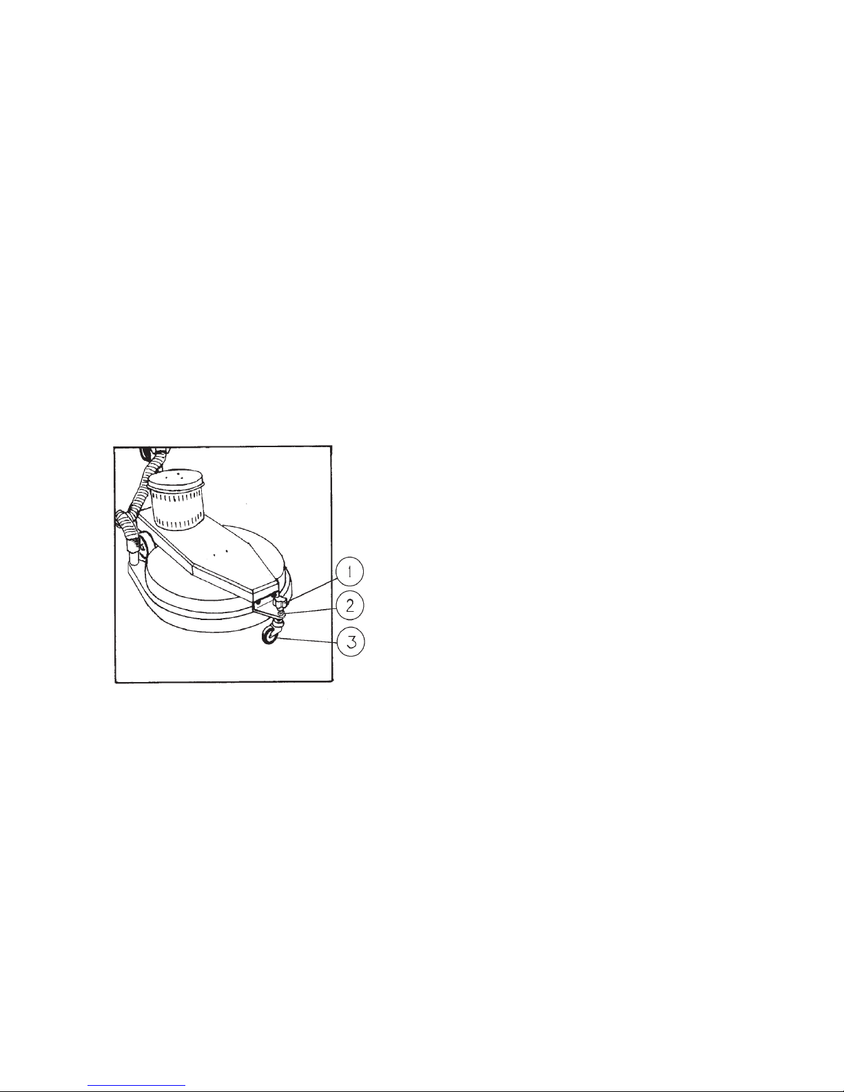
Adjusting the front caster is a simple, minor adjustment. Loosen the lock nut located under the
black adjustment knob. Turn the knob clockwise to raise the pad and reduce pad pressure. Turn
the knob counter clockwise to lower the pad and increase pad pressure. Adjust the pad height
up or down to achieve a slight drag on the motor when in operation. DO NOT OVERLOAD THE
MOTOR BY SETTING THE PAD TOO LOW. Make only minor adjustments and make a test
pass with the machine. Compare the sheen after each pass. When the adjustment is completed,
retighten the lock nut against the bracket to hold the pad height at the selected level.
MAINTENANCE OF MACHINE
WARNING: MAINTENANCE SHOULD BE PERFORMED BY QUALIFIED PERSONNEL ONLY.
Your Fiorentini standard speed floor machine is a very rugged, durable machine which requires
very little maintenance or upkeep. the previously described PRESTART-UP CHECKS, if performed, should reveal any potential operational problems or hazards which may be present.
Lubrication
: your machine has been completely lubricated at the factory before shipment to you.
The gear unit is lubricated for 2 or 3 years (for normal work).
Reasonable care and skillshould be used when servicing or making repairs to your machine.
DO NOT ALLOW UNSKILLED PERSONNEL TO OPERATE OR PERFORM REPAIRS TO
YOUR MACHINE.
If necessary, contact your local Fiorentini Distributor for assistence. Each and every component
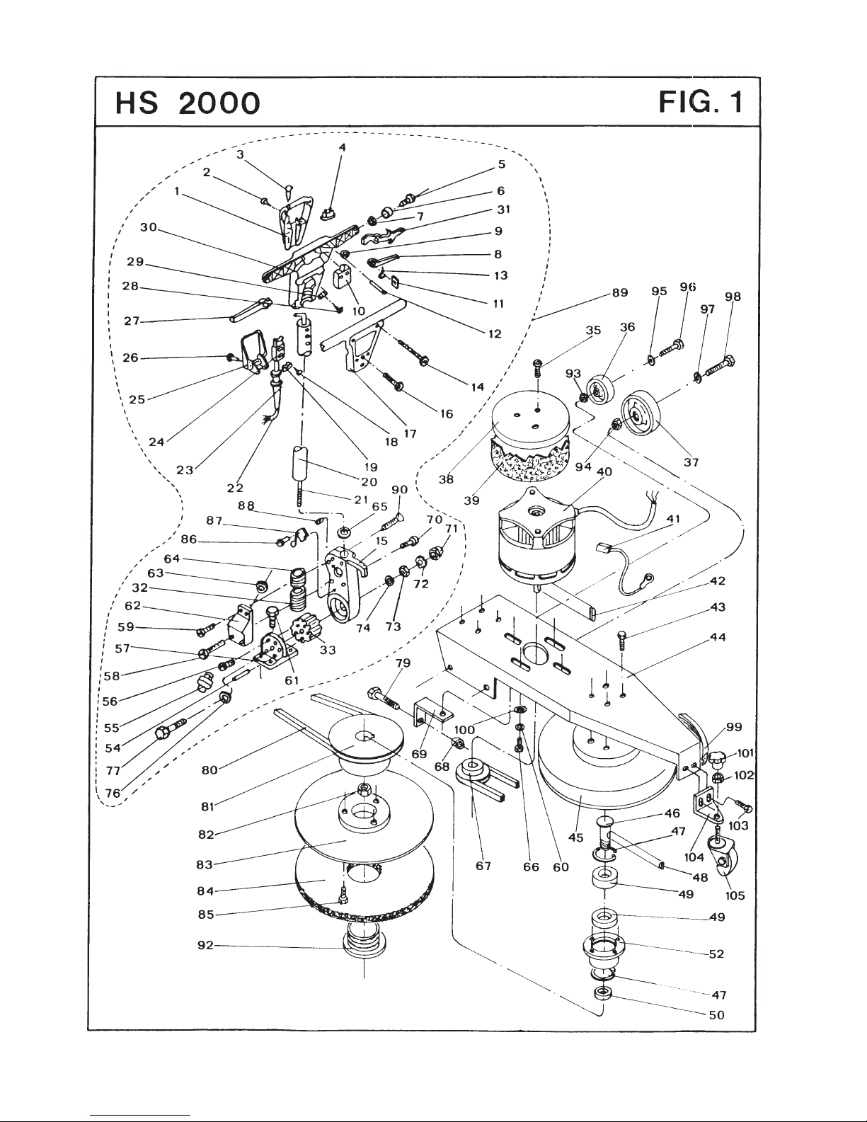
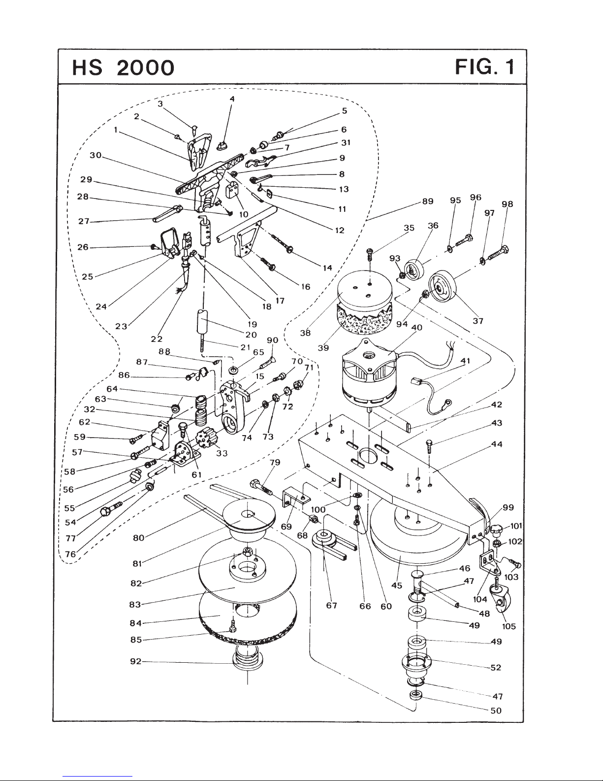
of this machine is available as a service part through your Distributor. An exploded view of the
handle assembly and the machine base are provided with descriptions and part numbers to assist in proper identification of parts and ordering. The following outlines provide step-by-step procedures for performing routine repairs to your machine.
DRIVE BELT ADJUSTMENT PROCEDURES
Periodic adjustment of the DRIVE BELT will prolong the service life of the belt and maintain the
level of performance expected of the machine. A squeal will come from the machine on atartup
when the belt needs tightening. When this happens, do not continue to operate the machine until
the belt has been properly adjusted.
1) Adjustment knob
2) Tightnening nut
3) Wheel
Page 6

1) Disconnect power cable from outlet (unplung machine).
2) Lock handle in full upright position.
3) Tilt machine back and allow it to rest on the handle block and wheels.
4) Remove the protection carter. Loosen four bolts attaching the motor to the base (do not remo-
ve bolts).
5) An “L” bracket is located at the rear of the machine with a bolt which extends out through the
rear portion of the base. Turn the nut on the out side of the base clockwise to tighten the belt.
Turn the nut on the outside of the base clockwise to tighten the belt. Tighten until there is no
play or deflection of the belt. DO NOT OVERTIGHTEN THE BELT AS THIS CAN DAMAGE THE
MOTOR AND PAD DRIVER HUB BEARING.
6) Tighten four bolts which hold the motor inplace and return machine to upright position.
DRIVE BELT REPLACEMENT
If replacement of the drive belt is necessary, use the following procedures:
1) Disconnect power cable from outlet (unplug machine).
2) Lock handle in the full upright position.
3) Tilt machine back and allow it to rest on the handle block and wheels.
4) Remove the protection carter. Loosen four bolts attaching the motor to the base. (do not re-
move bolts).
5) Turn nut on the bolt in the “L” bracket counter-clockwise to loosen the drive belt.
6) Remove pad lock ring and plate.
7) Lift off pad and remove three (3) phillips scrws holding the lock plate hub and lift off.
8) Remove three (3) screws holding the pad driver in place and lift off.
9) Remove drive belt and inspect pulleys for damage. Remplace if necessary.
10) Install new belt into grooves on pulleys.
11) Turn bolt in “L” bracket cloclwise to tighten the new belt. Tighten until there is no play in the
belt and stop. DO NOT OVERTIGHTEN THE BELT.
12) Tighten the bolts holding the motor in place. Replace the protection carter.
13) Reinstall pad driver with three (3) retaining screws.
14) Reinstall lock plate hub with three (3) phillips head screws.
15) Install pad, lock ring and plate.
16) Return machine to upright position.
Routine lubrification of wheels with a light spry lubricant and general good cleaning will also help
keep your high quality Fiorentini floor machine operating at peak performance.
Your local Fiorentini floor machine Distributor can provide any parts or accessory items needed for your machine.
An exploded view of the handle assembly and base units are provided for your information along
with a parts listing with descriptions to identify any part needed to keep your machine in operation for years to come.
If you need assistance with service or maintenance of your machine, contact your local Distributor or our Technical Service Departement.
MOTOR BRUSH REPLACEMENT
1) Disconnect power cable from outlet (unplug machine).
2) Release camlock lever and lay handle flat or tilt back to allow access to motor.
3) Unplug motor powered lead from lead at base of handle fork.
1) Protection carter
2) “L” bracket
3) Bolts attaching the motor
4) Belt
Page 7
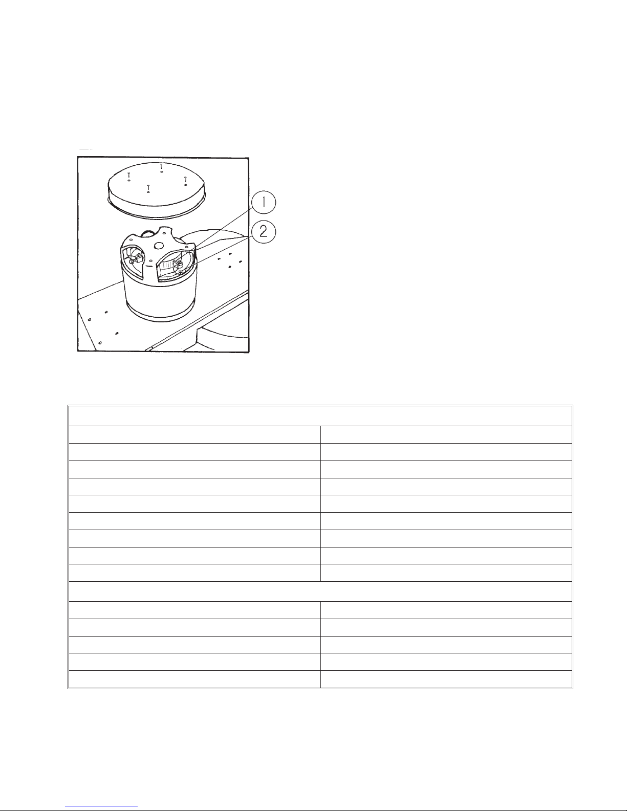
4) Remove four (4) Truss Head Phillips screws from drip cover and lift off.
5) The 1.5 HP Motor on your machine has four (4) brushes with leads connected to the brush
plate. The leads are fastened to the plate with a brass screw located to the left of the brush holder. Loosen but do not remove these screws.
6) Remove brushes from brush holders and replace with new brushes.
7) Reconnect brush leads and tighten brass retaining screws.
8) Reinstall drip cover and connect power lead.
9) Return handle to full upright position and lock.
10) Reconnect power cable to outlet (plug in machine) and test the machine.
1) Motor brush
2) Brushes with
TECNICAL CHARACTERISTICS
POWER 1100 W
PROTECTION CLASS 1
LENGTH OF CORDS 15 m
BRUSH SIZE 480 mm
BRUSH REVS. 2000 rpm
ENERGY SOURCE direct current
VOLT 220 v
WEIGHT 35 Kg
DECIBEL 70 dB
OPTIONAL (VACUUM ATTACHMENT)
POWER 800 W
AIR FLOW 51 L/s
DEPRESSION 195 mbar
WEIGHT 10 Kg
DECIBEL 77 dB
Page 8
Page 9
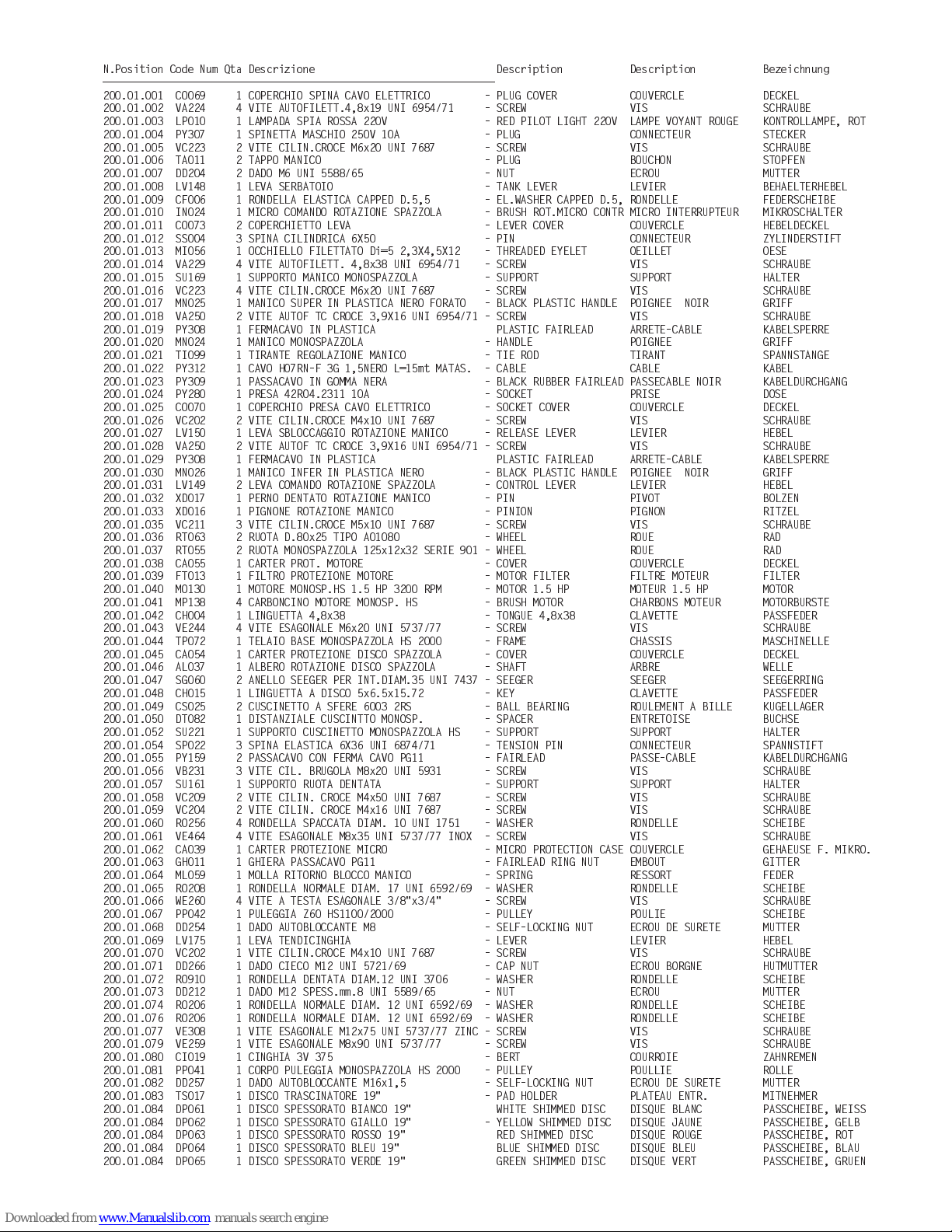
N.Position Code Num Qta Descrizione Description Description Bezeichnung
-
200.01.001 CO069 1 COPERCHIO SPINA CAVO ELETTRICO - PLUG COVER COUVERCLE DECKEL
200.01.002 VA224 4 VITE AUTOFILETT.4,8x19 UNI 6954/71 - SCREW VIS SCHRAUBE
200.01.003 LP010 1 LAMPADA SPIA ROSSA 220V - RED PILOT LIGHT 220V LAMPE VOYANT ROUGE KONTROLLAMPE, ROT
200.01.004 PY307 1 SPINETTA MASCHIO 250V 10A - PLUG CONNECTEUR STECKER
200.01.005 VC223 2 VITE CILIN.CROCE M6x20 UNI 7687 - SCREW VIS SCHRAUBE
200.01.006 TA011 2 TAPPO MANICO - PLUG BOUCHON STOPFEN
200.01.007 DD204 2 DADO M6 UNI 5588/65 - NUT ECROU MUTTER
200.01.008 LV148 1 LEVA SERBATOIO - TANK LEVER LEVIER BEHAELTERHEBEL
200.01.009 CF006 1 RONDELLA ELASTICA CAPPED D.5,5 - EL.WASHER CAPPED D.5, RONDELLE FEDERSCHEIBE
200.01.010 IN024 1 MICRO COMANDO ROTAZIONE SPAZZOLA - BRUSH ROT.MICRO CONTR MICRO INTERRUPTEUR MIKROSCHALTER
200.01.011 CO073 2 COPERCHIETTO LEVA - LEVER COVER COUVERCLE HEBELDECKEL
200.01.012 SS004 3 SPINA CILINDRICA 6X50 - PIN CONNECTEUR ZYLINDERSTIFT
200.01.013 MI056 1 OCCHIELLO FILETTATO Di=5 2,3X4,5X1 2 - THREADED EYELET OEILLET OESE
200.01.014 VA229 4 VITE AUTOFILETT. 4,8x38 UNI 6954/71 - SCREW VIS SCHRAUBE
200.01.015 SU169 1 SUPPORTO MANICO MONOSPAZZOLA - SUPPORT SUPPORT HALTER
200.01.016 VC223 4 VITE CILIN.CROCE M6x20 UNI 7687 - SCREW VIS SCHRAUBE
200.01.017 MN025 1 MANICO SUPER IN PLASTICA NERO FORATO - BLACK PLASTIC HANDLE POIGNEE NOIR GRIFF
200.01.018 VA250 2 VITE AUTOF TC CROCE 3,9X16 UNI 6954/71 - SCREW VIS SCHRAUB E
200.01.019 PY308 1 FERMACAVO IN PLASTICA PLASTIC FAIRLEAD ARRETE-CABLE KABELSPERRE
200.01.020 MN024 1 MANICO MONOSPAZZOLA - HANDLE POIGNEE GRIFF
200.01.021 TI099 1 TIRANTE REGOLAZIONE MANICO - TIE ROD TIRANT SPANNSTANGE
200.01.022 PY312 1 CAVO H07RN-F 3G 1,5NERO L=15mt MATAS. - CABLE CABLE KABEL
200.01.023 PY309 1 PASSACAVO IN GOMMA NERA - BLACK RUBBER FAIRLEAD PASSECABLE NOIR KABELDURCHGANG
200.01.024 PY280 1 PRESA 42RO4.2311 10A - SOCKET PRISE DOSE
200.01.025 CO070 1 COPERCHIO PRESA CAVO ELETTRICO - SOCKET COVER COUVERCLE DECKEL
200.01.026 VC202 2 VITE CILIN.CROCE M4x10 UNI 7687 - SCREW VIS SCHRAUBE
200.01.027 LV150 1 LEVA SBLOCCAGGIO ROTAZIONE MANICO - RELEASE LEVER LEVIER HEBEL
200.01.028 VA250 2 VITE AUTOF TC CROCE 3,9X16 UNI 6954/71 - SCREW VIS SCHRAUBE
200.01.029 PY308 1 FERMACAVO IN PLASTICA PLASTIC FAIRLEAD ARRETE-CABLE KABELSPERRE
200.01.030 MN026 1 MANICO INFER IN PLASTICA NERO - BLACK PLASTIC HANDLE POIGNEE NOIR GRIFF
200.01.031 LV149 2 LEVA COMANDO ROTAZIONE SPAZZOLA - CONTROL LEVER LEVIER HEBEL
200.01.032 XD017 1 PERNO DENTATO ROTAZIONE MANICO - PIN PIVOT BOLZEN
200.01.033 XD016 1 PIGNONE ROTAZIONE MANICO - PINION PIGNON RITZEL
200.01.035 VC211 3 VITE CILIN.CROCE M5x10 UNI 7687 - SCREW VIS SCHRAUBE
200.01.036 RT063 2 RUOTA D.80x25 TIPO A01080 - WHEEL ROUE RAD
200.01.037 RT055 2 RUOTA MONOSPAZZOLA 125x12x32 SERIE 901 - WHEEL ROUE RAD
200.01.038 CA055 1 CARTER PROT. MOTORE - COVER COUVERCLE DECKEL
200.01.039 FT013 1 FILTRO PROTEZIONE MOTORE - MOTOR FILTER FILTRE MOTEUR FILTER
200.01.040 MO130 1 MOTORE MONOSP.HS 1.5 HP 3200 RPM - MOTOR 1.5 HP MOTEUR 1.5 HP MOTOR
200.01.041 MP138 4 CARBONCINO MOTORE MONOSP. HS - BRUSH MOTOR CHARBONS MOTEUR MOTORBURSTE
200.01.042 CH004 1 LINGUETTA 4,8x38 - TONGUE 4,8x38 CLAVETTE PASSFEDER
200.01.043 VE244 4 VITE ESAGONALE M6x20 UNI 5737/77 - SCREW VIS SCHRAUBE
200.01.044 TP072 1 TELAIO BASE MONOSPAZZOLA HS 2000 - FRAME CHASSIS MASCHINELLE
200.01.045 CA054 1 CARTER PROTEZIONE DISCO SPAZZOLA - COVER COUVERCLE DECKEL
200.01.046 AL037 1 ALBERO ROTAZIONE DISCO SPAZZOLA - SHAFT ARBRE WELLE
200.01.047 SG060 2 ANELLO SEEGER PER INT.DIAM.35 UNI 7437 - SEEGER SEEGER SEEGERRING
200.01.048 CH015 1 LINGUETTA A DISCO 5x6.5x15.72 - KEY CLAVETTE PASSFEDER
200.01.049 CS025 2 CUSCINETTO A SFERE 6003 2RS - BALL BEARING ROULEMENT A BILLE KUGELLAGER
200.01.050 DT082 1 DISTANZIALE CUSCINTTO MONOSP. - SPACER ENTRETOISE BUCHSE
200.01.052 SU221 1 SUPPORTO CUSCINETTO MONOSPAZZOLA HS - SUPPORT SUPPORT HALTER
200.01.054 SP022 3 SPINA ELASTICA 6X36 UNI 6874/71 - TENSION PIN CONNECTEUR SPANNSTIFT
200.01.055 PY159 2 PASSACAVO CON FERMA CAVO PG11 - FAIRLEAD PASSE-CABLE KABELDURCHGANG
200.01.056 VB231 3 VITE CIL. BRUGOLA M8x20 UNI 5931 - SCREW VIS SCHRAUBE
200.01.057 SU161 1 SUPPORTO RUOTA DENTATA - SUPPORT SUPPORT HALTER
200.01.058 VC209 2 VITE CILIN. CROCE M4x50 UNI 7687 - SCREW VIS SCHRAUBE
200.01.059 VC204 2 VITE CILIN. CROCE M4x16 UNI 7687 - SCREW VIS SCHRAUBE
200.01.060 RO256 4 RONDELLA SPACCATA DIAM. 10 UNI 1751 - WASHER RONDELLE SCHEIBE
200.01.061 VE464 4 VITE ESAGONALE M8x35 UNI 5737/77 INOX - SCREW VIS SCHRAUBE
200.01.062 CA039 1 CARTER PROTEZIONE MICRO - MICRO PROTECTION CASE COUVERCLE GEHAEUSE F. MIKRO.
200.01.063 GH011 1 GHIERA PASSACAVO PG11 - FAIRLEAD RING NUT EMBOUT GITTER
200.01.064 ML059 1 MOLLA RITORNO BLOCCO MANICO - SPRING RESSORT FEDER
200.01.065 RO208 1 RONDELLA NORMALE DIAM. 17 UNI 6592/69 - WASHER RONDELLE SCHEIBE
200.01.066 WE260 4 VITE A TESTA ESAGONALE 3/8"x3/4" - SCREW VIS SCHRAUBE
200.01.067 PP042 1 PULEGGIA Z60 HS1100/2000 - PULLEY POULIE SCHEIBE
200.01.068 DD254 1 DADO AUTOBLOCCANTE M8 - SELF-LOCKING NUT ECROU DE SURETE MUTTER
200.01.069 LV175 1 LEVA TENDICINGHIA - LEVER LEVIER HEBEL
200.01.070 VC202 1 VITE CILIN.CROCE M4x10 UNI 7687 - SCREW VIS SCHRAUBE
200.01.071 DD266 1 DADO CIECO M12 UNI 5721/69 - CAP NUT ECROU BORGNE HUTMUTTER
200.01.072 RO910 1 RONDELLA DENTATA DIAM.12 UNI 3706 - WASHER RONDELLE SCHEIBE
200.01.073 DD212 1 DADO M12 SPESS.mm.8 UNI 5589/65 - NUT ECROU MUTTER
200.01.074 RO206 1 RONDELLA NORMALE DIAM. 12 UNI 6592/69 - WASHER RONDELLE SCHEIBE
200.01.076 RO206 1 RONDELLA NORMALE DIAM. 12 UNI 6592/69 - WASHER RONDELLE SCHEIBE
200.01.077 VE308 1 VITE ESAGONALE M12x75 UNI 5737/77 ZINC - SCREW VIS SCHRAUBE
200.01.079 VE259 1 VITE ESAGONALE M8x90 UNI 5737/77 - SCREW VIS SCHRAUBE
200.01.080 CI019 1 CINGHIA 3V 375 - BERT COURROIE ZAHNREMEN
200.01.081 PP041 1 CORPO PULEGGIA MONOSPAZZOLA HS 2000 - PULLEY POULLIE ROLLE
200.01.082 DD257 1 DADO AUTOBLOCCANTE M16x1,5 - SELF-LOCKING NUT ECROU DE SURETE MUTTER
200.01.083 TS017 1 DISCO TRASCINATORE 19" - PAD HOLDER PLATEAU ENTR. MITNEHMER
200.01.084 DP061 1 DISCO SPESSORATO BIANCO 19" WHITE SHIMMED DISC D ISQUE BLANC PASSCHEIBE, WEISS
200.01.084 DP062 1 DISCO SPESSORATO GIALLO 19" - YELLOW SHIMMED DISC DISQUE JAUNE PASSCHEIBE, GELB
200.01.084 DP063 1 DISCO SPESSORATO ROSSO 19" RED SHIMMED DISC DISQUE ROUGE PASSCHEIBE, ROT
200.01.084 DP064 1 DISCO SPESSORATO BLEU 19" BLUE SHIMMED DISC DISQUE BLEU PASSCHEIBE, BLAU
200.01.084 DP065 1 DISCO SPESSORATO VERDE 19" GREEN SHIMMED DISC DISQUE VERT PASSCHEIBE, GRUEN
Page 10
Page 11
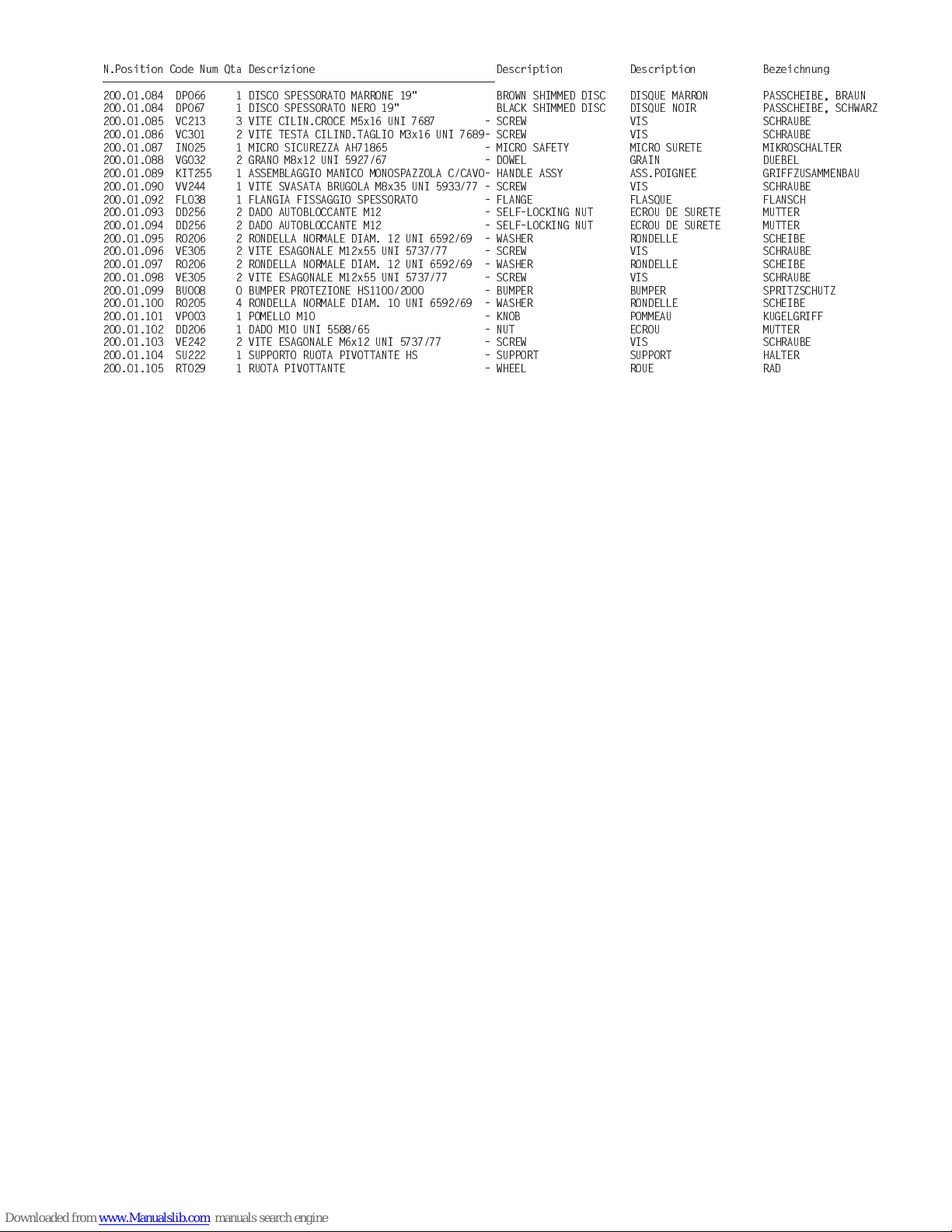
N.Position Code Num Qta Descrizione Description Description Bezeichnung
-
200.01.084 DP066 1 DISCO SPESSORATO MARRONE 19" BROWN SHIMMED DISC DISQUE MARRON PASSCHEIBE, BRAUN
200.01.084 DP067 1 DISCO SPESSORATO NERO 19" BLACK SHIMMED DISC DISQUE NOIR PASSCHEIBE, SCHWARZ
200.01.085 VC213 3 VITE CILIN.CROCE M5x16 UNI 7687 - SCREW VIS SCHRAUBE
200.01.086 VC301 2 VITE TESTA CILIND.TAGLIO M3x16 UNI 7689- SCREW VIS SCHRAUBE
200.01.087 IN025 1 MICRO SICUREZZA AH71865 - MICRO SAFETY MICRO SURETE MIKROSCHALTER
200.01.088 VG032 2 GRANO M8x12 UNI 5927/67 - DOWEL GRAIN DUEBEL
200.01.089 KIT255 1 ASSEMBLA GGIO MANICO MONOSPAZZOLA C/CAVO- HANDLE ASSY ASS.POIGNEE GRIFFZUSAMMENBAU
200.01.090 VV244 1 VITE SVASATA BRUGOLA M8x35 UNI 5933/77 - SCREW VIS SCHRAUBE
200.01.092 FL038 1 FLANGIA FISSAGGIO SPESSORATO - FLANGE FLASQUE FLANSCH
200.01.093 DD256 2 DADO AUTOBLOCCANTE M12 - SELF-LOCKING NUT ECROU DE SURETE MUTTER
200.01.094 DD256 2 DADO AUTOBLOCCANTE M12 - SELF-LOCKING NUT ECROU DE SURETE MUTTER
200.01.095 RO206 2 RONDELLA NORMALE DIAM. 12 UNI 6592/69 - WASHER RONDELLE SCHEIBE
200.01.096 VE305 2 VITE ESAGONALE M12x55 UNI 5737/77 - SCREW VIS SCHRAUBE
200.01.097 RO206 2 RONDELLA NORMALE DIAM. 12 UNI 6592/69 - WASHER RONDELLE SCHEIBE
200.01.098 VE305 2 VITE ESAGONALE M12x55 UNI 5737/77 - SCREW VIS SCHRAUBE
200.01.099 BU008 0 BUMPER PROTEZIONE HS1100/2000 - BUMPER BUMPER SPRITZSCHUTZ
200.01.100 RO205 4 RONDELLA NORMALE DIAM. 10 UNI 6592/69 - WASHER RONDELLE SCHEIBE
200.01.101 VP003 1 POMELLO M10 - KNOB POMMEAU KUGELGRIFF
200.01.102 DD206 1 DADO M10 UNI 5588/65 - NUT ECROU MUTTER
200.01.103 VE242 2 VITE ESAGONALE M6x12 UNI 5737/77 - SCREW VIS SCHRAUBE
200.01.104 SU222 1 SUPPORTO RUOTA PIVOTTANTE HS - SUPPORT SUPPORT HALTER
200.01.105 RT029 1 RUOTA PIVOTTANTE - WHEEL ROUE RAD
Page 12
Page 13

N.Position Code Num Qta Descrizione Description Description Bezeichnung
-
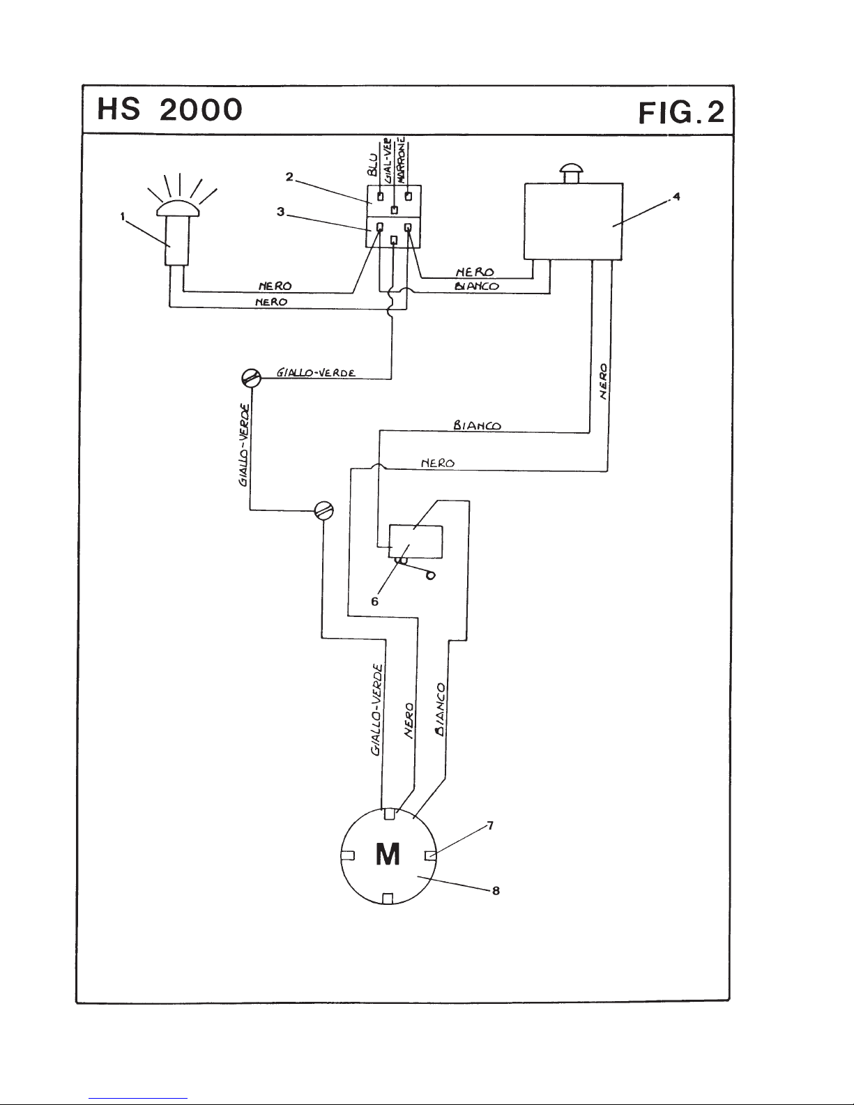
200.02.001 LP010 1 LAMPADA SPIA ROSSA 220V - RED PILOT LIGHT 220V LAMPE VOYANT ROUGE KONTROLLAMPE, ROT
200.02.002 PY280 1 PRESA 42RO4.2311 10A - SOCKET PRISE DOSE
200.02.003 PY307 1 SPINETTA MASCHIO 250V 10A - PLUG CONNECTEUR STECKER
200.02.004 IN024 1 MICRO COMANDO ROTAZIONE SPAZZOLA - BRUSH ROT.MICRO CONTR MICRO INTERRUPTEUR MIKROSCHALTER
200.02.006 IN025 1 MICRO SICUREZZA AH71865 - MICRO SAFETY MICRO SURETE MIKROSCHALTER
200.02.007 MP138 4 CARBONCINO MOTORE MONOSP. HS - BRUSH MOTOR CHARBONS MOTEUR MOTORBURSTE
200.02.008 MO130 1 MOTORE MONOSP.HS 1.5 HP 3200 RPM - MOTOR 1.5 HP MOTEUR 1.5 HP MOTOR
Page 14
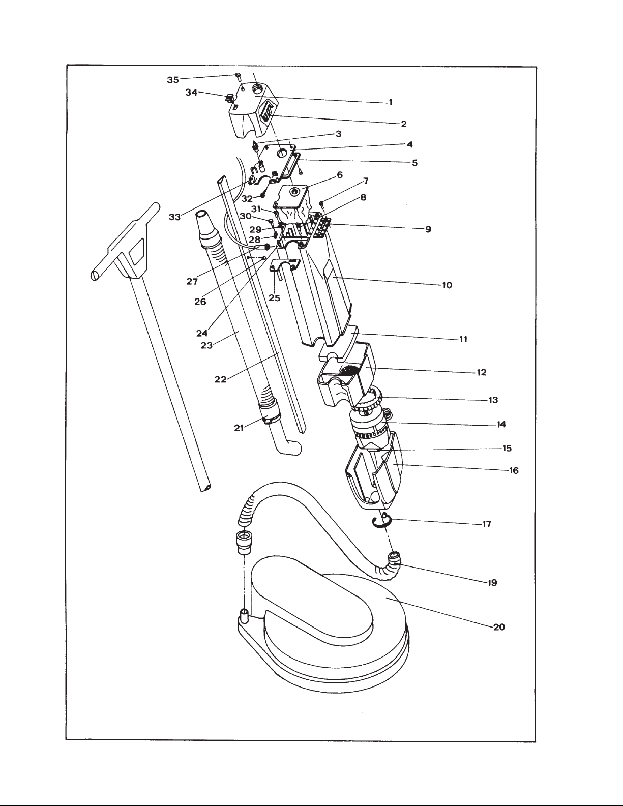
Page 15
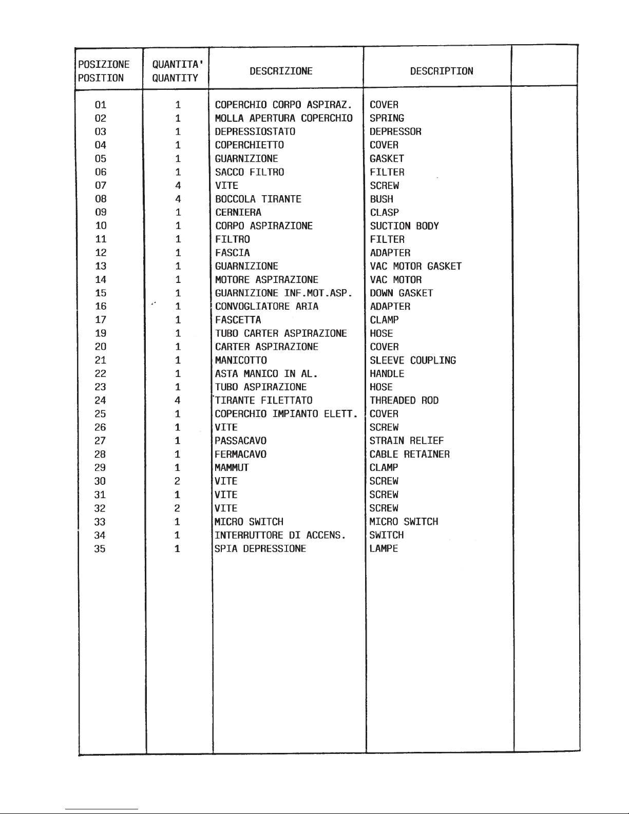
Page 16

Mat. n.
Serial no.
Nr. de serie
Data di spedizione
Date of shipment
Date de spedition
ING. O. FIORENTINI s.r.l.
“ The Best in floor machines ”
FILIALI:
20132 MILANO - Fax. 02/2592779
Via Palmanova 211/a - Tel02/27207783 - 2564810
00155 ROMA - Fax. 06/22754075
Via Carlo Carrà 13 - Tel. 06/22754040 - 2275060
STABILIMENTO:
50030 PIANCALDOLI ( FI ) - Fax. 055/817144
Loc. Rombola - Tel. 055/817092 - 817093
Distribuito da:
 Loading...