

Page 1

FINOCAM A5
06260DE
Original FINO
Germany
Tischfräsmaschine
Table Milling Unit
Gebrauchsinformation•User Information•Mode d’emploi
Información sobre el uso•Informazioni d’uso
Gebruiksaanwijzing•Instrukcja stosowania
FINO
•der feine Unterschied•the fine difference•la fine différence•la fina diferencia•la fine differenza
Page 2

Version 1/2016. Read the User Manual prior to commencing work!
1. About this document 3
• Used symbols • Structure of safety notes
2. Safety instructions & regulations 3
• General safety instructions • Regulations
3. Machine description 6
• Connection panel• Front cover• Working chamber • Accessories container
• Air extraction concept • Manufacturing software and computer • Sound emission
• Technical data
4. Installing the machine 11
• Checking the scope of delivery • Choosing the installation site
• Machine installation (scheme) • Installing the pneumatics
• Installing the air extraction system • Establishing the electric connection
• Removing the transport lock • Connecting the manufacturing computer
• Testing the machine
5. Running the machine 18
• Starting up the machine • Job execution overview • Inserting/changing tools
• Inserting and removing workpieces • Executing jobs • Interrupting the job execution
• Operation interruption or abortion of job execution • Emergency release of the front cover
6. Machine maintenance and cleaning 25
• Definition of wear parts • Maintenance table • Inspection
• Cleaning the working chamber and measuring key • Cleaning the collet chuck
• Checking the hoses, cables and connections • Cleaning the housing
• Checking the service unit • Exchanging the main fuse • Calibrating the axes
• Replacing the tool changer inserts
7. Disposal 32
8. Troubleshooting 32
9. Index 36
CONTENTS
2
Page 3

1. About this document
1.1 Used symbols
Instructions
➤ General instruction
M Specific m
anual action
S Specific action in the manufacturing software
➡ Result
Additional symbols
➲ Cross reference
• List
Information to make work more efficient.
Important instructions without any danger
for people or objects.
Additional information
Structure of safety notes
Type and source of hazard
Further explanations and consequences when ignoring hazards.
➤ Instructions to avoid hazards.
The following signal words may occur in this document:
DANGER indicates a hazardous situation which will
result in death or serious injury.
WARNING indicates a hazardous situation which can
result in death or serious injury.
CAUTION indicates a hazardous situation which, if
not avoided, can result in minor or moderate injury.
NOTICE indicates a situation which can lead to physical damage of the product or in the surrounding
area(s).
SIGNAL WORD
DANGER
WARNING
CAUTION
NOTICE
2. Safety instructions & regulations
2.1 General safety instructions
Incorrect operation of the machine
➤ Read this document carefully before installing
and operating the machine.
➤ If it is unclear how to operate the machine in
any way, do not use the machine and contact
customer service.
➤ Make sure that every user has access to this
document.
➤ Instruct every user on safe and proper machine
handling.
Danger to life due to an electric shock
If you come into contact with electrically
charged parts, you can suffer from an elec tric shock. Water increases the risk significantly.
➤ Do not remove the housing of the machine.
➤ Only have qualified electricians work on any
electric equipment.
➤ Run power cables so that they cannot be dama-
ged by sharp edges.
➤ In the following cases, disconnect the
machine from the electrical source immediately and prevent it from being restarted:
• When machine connections, compressed air
hoses or electric cables are damaged
• Before you check or run electric cables
➤ Never perform any troubleshooting while the
machine is operating.
➤ Only have authorized service technicians repair
the machine.
➤ Replace damaged cables with original manu-
facturer’s spare parts.
➤ Install an operational Residual Current Device/
Ground Fault Circuit Interrupter on the electric
circuit of the machine.
➤ Do not touch the machine and especially the
cables with wet or damp hands.
➤ Remove any liquids near the machine imme -
diately.
DANGER
3
ENU
!
!
!
!
!
Page 4

Respiratory diseases when processing
harmful materials
If you inhale harmful materials during their processing, your respiratory tracts may be damaged.
➤ Only process materials when an air extraction
system is running.
➤ Avoid materials which can damage your health
during dry machining.
➤ Use a suction device with an extra-fine particle
filter.
Crushing hazard and risk of cutting injuries
through moving machine parts
Through the moving axes and the rotating spindle
you can suffer bruises and cuts.
➤ Only operate the machine when the front cover
is closed and the safety interlock is activated.
➤ Store the key for the emergency release in a
place where only authorised persons have
access.
➤ Do not circumvent or deactivate safety devices
of the machine.
➤ Check the machine regularly for damage,
especially the safety devices.
➤ Have damaged safety devices repaired by an
authorised service centre unless stated other wise in this document.
➤ Use only original manufacturer’s equipment and
original spare parts in the machine.
➤ Keep children and animals away from the
machine.
➤ Do not remove the housing of the machine.
Administrator mode: risk of cutting injuries
and bruises as well as hazards through
ejected debris
If you operate the machine in “Administrator mode”
with the front cover open, the risk of injury is increased significantly!
➤ Operate the machine in “User“ mode only unless
you have been authorised by FINO GmbH to use
other profiles.
➤ Even if you are an authorised user, use the
“Administrator mode” with the front cover open
only when necessary.
WARNING
!
➤ While in “Administrator mode”: Do not
reach into the working chamber while
the axes are moving or during machining.
➤ While in “Administrator mode”:
Everyone within reach of the machine
must wear protective eye wear.
Hearing damage due to loud noise
➤ In case of extraneous machining noise check the
working conditions: Ensure that the workpiece is
fixed properly, and verify the condition of the
tool and the material you are using.
➤ If loud noise cannot be avoided, wear
ear protection during processing.
Risk of injuries through loose pneumatic components under air pressure when connections
are open
Loose pneumatic components can move extremely
fast and unpredictably and may cause injury.
➤ Before you run the pneumatic hoses, close the
compressed air supply valve.
➤ Before you check the pneumatic hoses and
pneumatic connections, set the air pressure to a
minimum value.
➤ In case of defective machine connections
and pneumatic hoses, disconnect the
machine from the external compressed air
supply and the electrical source to prevent
it from being re started.
➤ Contact customer service if connections are
damaged or defective.
4
Page 5

Trip, fall and slipping hazards
➤ Keep the working environment and
installation site clean.
➤ Run cables in such a way that persons
cannot trip over them.
Risk of cutting injuries and burns
If you touch tools or sharp edges on workpieces or
the machine, you may suffer from cuts. If you touch
the hot spindle body or hot tools, you may suffer
from burns.
➤ Wear gloves when you perform manual work at
the machine or with workpieces/tools.
Reduced ability to act with insufficient lighting
In case of an insufficient lighting your judgement
and/or your precision may be reduced.
➤ Make sure that the lighting in your working
environment is sufficient.
Risk of injury in case of malfunctions caused
by insufficient maintenance
If you do not maintain the machine as often as is
required, malfunctions may occur which can lead to
injuries.
➤ Take note of the intervals and conditions mentio-
ned in the maintenance table in this document
and carry out the respective maintenance steps
accordingly.
Health risks through constant malpositioning
if your working environment is not sufficiently
ergonomic
Over the long run, an improper or one-sided positioning can be a risk to your health.
➤ Set up an ergonomic work environment.
➤ Ensure the seat height and monitor position is
ideal and the lighting is sufficient.
CAUTION
2.2 Regulations
If you violate the following regulations, you may lose
your entitlement for benefits. In addition, we cannot
be held liable for any damage resulting from such
violations.
2.2.1 Intended use
The FINOCAM A5 has been designed for easy to
medium machining work in the dental sector.
➤ Only process materials that you can select in
FINOCAM. Only use the machine commer cially.
➤ Before creating jobs, verify if the objects being
prepared may be utilized at the place of use
according to local and/or national regulations or
other authorized organisations or entities (e. g.
professional associations, health authorities). In
particular, verify if the material is approved for
the machined object type and if the object type
is designed in accordance with applicable regulations. Neither the manufacturing software nor
the CNC machine will inform you about possible
regulatory infringements, but will executes jobs
in accordance with the preferences and materials set by the user.
➤ Verify that each object type and each material in
your jobs are authorized to manufacturing materials. If mandated by local or national regula tions, obtain relevant authorization from the
responsible organisation or entities (e. g. professional associations, health authorities).
➤ Only manufacture objects which correspond to
the object types that you can select in the import
view in FINOCAM. While you can import/manufacture any other objects as well, neither the
manufacturing software nor the CNC machine
are designed for these other objects and should
not be used in this way.
➤ Do not manufacture implants or parts of objects
that are designed to have contact with implants.
These parts include parts of two-part abutments
which contain the connection geometry for the
implant. Do not manipulate the connection geometry of prefabricated abutments (“prefab abutments”) and you must always check finished
objects for accurate connection geometries (i.e.
that connection geometries of finished jobs have
not been damaged).
5
ENU
!
Page 6

2.2.2 Controlling the machine through
software
You control the CNC machine through specially
designed applications which are supplied with the
machine.
➤ Only use program versions that are officially
released for the machine.
➤ Always use the newest program versions that
are available for the machine.
➤ Before installing or operating the machine, be
sure to read the documentation for the applications.
2.2.3 Maintenance and cleaning
➤ Clean and maintain the CNC machine as
required. Only then can the machine reach a
long service life.
➤ Only carry out maintenance work which is de -
scribed in this document. Otherwise you risk
your health and may damage the machine.
2.2.4 Synchronous spindle SFK 300P
➤ Do not use unbalanced tools at high rotational
speeds. Such an imbalance puts a great strain
on the spindle’s ball bearings, which can cause
the bearings to be dam- aged.
➤ When working in the working chamber, do not
apply manual pressure against the spindle.
2.2.5 Unattended operation
➤ Unattended operation of the CNC machine
should only occur if the following conditions are
met:
• The national and local laws allow it.
• The working chamber of the machine is completely clean.
• Unauthorized users cannot access the machine.
• The room in which the machine is located has an
automatic fire detection system.
2.2.6 Transport ation and storage
Damaging of the machine if you transport the
machine without the transport lock
If you transport the machine without installing the
transport lock first, the machine may get damaged.
➤ Before every transport, install the transport lock
as it was installed at delivery
• Ambient temperature: between 10 °C and 35 °C
• Relative air moisture: max. 80 %, non-condensing
• For (un)packing and positioning two people are
required
• Weight of the machine: approx. 91 kg
➤ Always transport multiple machines
individually and do not stack them.
➤ Only trained transport personnel may transport
the machine to the installation site.
➤ Always transport the machine in an upright posi-
tion.
➤ Transport and position the machine only with a
closed accessories container.
➤ In case of overseas transport, take proper
measures against corrosion.
➤ To carry the machine, use the left and right grips
located on the bottom of the machine.
3. Machine description
Fig. 1: Front view of the FINOCAM A5
NOTICE
6
Page 7

1 Connection panel (➲ Fig. 2)
2 Front cover
3 View window to the working chamber
4 Recessed grip for opening
5 Accessories container
6 Opening for the air extraction system
With your FINOCAM A5 you can process workpieces
of different materials to create high quality objects
for the dental sector.
You can find a list of the materials which you can
process with the FINOCAM A5 in the FINOCAM
manufacturing software.
3.1 Connection panel
Fig. 2: The connection panel
1 Power connection 100 – 240 V AC, 50/60 Hz,
including glass fuse T6,3A L250V
2 Main power switch
3 Pneumatic connection
4 USB connection
5 Switching output for suction device
3.2 Front cover
The front cover locks the working chamber and
protects the user from injuries during operation.
Crushing hazard when opening or closing the
front cover
When you open or close the front cover, the moving
front cover may crush your fingers.
➤ When you open and close the front cover, use
one hand and keep the other hand away from the
machine.
➤ When you close the front cover, ensure your
hands do not get caught between the front cover
and the machine housing.
CAUTION
Damaging of the machine when opening the
front cover by force
When the CNC machine is not supplied with power or
when the axes are moving, the front cover remains
locked. If you open the locked front cover by force,
the machine may get damaged.
➤ Never open the front cover by force.
➤ Connect the machine to the electrical source
and switch it on first before opening the front
cover.
➤ To open the front cover, grasp the recessed grip
and pull the front cover upwards.
Fig. 3: The FINOCAM A5 with the front cover open
➤ To close the front cover, put your hand flat on
the upper edge of the front cover and push the
front cover downwards.
3.3 Working chamber
The machine processes all workpieces in the working
chamber.
Fig. 4: The working chamber of the FINOCAM A5
NOTICE
7
ENU
!
Page 8

1 Rotational axis B
2 Workpiece holder and rotational axis A
3 Fixing disc
4 Collet chuck for picking up tools
5 Spindle
6 Tool changer for up to 16 tools
Colours of the working chamber lighting
If the working chamber lighting is insufficient,
provide additional lighting.
Your FINOCAM A5 illuminates the working chamber
in different colours. The colour will change depending on the state of the machine. You will find the
colours and respective machine statuses in the following table:
3.4 Accessories container
In the accessories container below the working
chamber, you can store workpieces, tools, and the
spindle service set ready to hand.
➤ To access the accessories container, simply pull
it out of machine.
Fig. 5: Opening the accessories container
Colour Status
Green Machine is ready, front cover closed
White Machine is ready, front cover closed
Blue Machine is executing a job
Red A machine malfunction has occurred
8
Fig. 6: The open accessories container
(blanks and tools not provided)
➤ To close the accessories container, push it into
the machine until it is completely closed.
3.5 Air extraction concept
The air extraction concept consists of:
• Air that is emitted from the spindle and the
bellow
• The external air extraction system (suction
device, suction hose, optional switching unit)
• The vacuum sensor
During job execution, the machine constantly blows
air into the working chamber (➲ Fig. 7, upper arrows).
An external suction device that you connect to the
CNC machine with a suction hose extracts the
machining debris from the working chamber (➲ Fig.
7, lower arrow).
This concept decreases the soiling and wear of
sensitive machine parts.
The air extraction system does not replace the
regular cleaning of the machine. Without regular
cleaning, the machine life decreases signifi cantly.
Through the air extraction, a vacuum develops in the
working chamber which is constantly monitored by a
vacuum sensor (display in FINOCNC:
➲ chapter
4.9). If the vacuum is too weak, machining is not
possible. If the vacuum becomes too weak during a
running job, FINOCNC interrupts machining until the
vacuum is sufficient again (➲ chapter 5.7).
The current strength of the vacuum displays in
FINOCNC (➲ chapter 4.9 or in documentation for the
manufacturing software).
Page 9

Sound measurement
Measuring conditions:
• Processed material: CoCr
• Tool status: new
• Distance to sound source: 1 m
• Measurement according to ISO 3746,
engineering method 3
3.8 Technical data
Base system
• Dimensions (W/D/H):
approx. 450 x 530 x 630 mm
• Weight: approx. 91 kg
• Air pressure (min./max.): 6 bar/8 bar
• Recommended air pressure: 7 bar
• Air consumption: ca. 40 l/min at 6 bar,
approx. 50 l/min at 8 bar
• 5-axis mechanism;
positioning range (x/y/z): 165.5 x 108 x 93 mm
• Complete housing of the working chamber;
front cover with a safety contact and safety
interlock
• Vacuum sensor for monitoring the extraction
capacity
• Minimum extraction capacity: 2500 l/min
• Accessories container in drawer shape
• Working chamber lighting with different colours
to indicate the machine state
Rotary axes
• Rotation range: 360 ° (A) | ±35 ° (B)
• Exchangeable workpiece holder
Spindle
• Synchronous spindle rotating up to 60,000 RPM
• Nominal power under continuous load (S1):
300 Watts
• Maximal Power (Pmax): 500 Watts
• 4-fold bearing
• Hybrid ceramic ball bearing
• Pneumatic collet chuck ø 3 mm
• Cone cleaning and sealing air
Operating condition Maximum A-weighted
sound pressure level
Processing 71 dB(A)
All other operating
conditions (tool change,
movement of the axes
etc.)
<70 dB(A)
9
ENU
Fig. 7: Air extraction concept in the working chamber
3.6 Manufacturing software and
computer
To operate the machine, you must use a computer
running Windows®(“manufacturing computer“)
which should connect to the machine via the provided USB cable.
You can process manufacturing jobs with the manufacturing computer in 2 steps:
1. With FINOCAM you can create jobs with the
objects that you want to machine. FINOCAM
already contains all important parameters for the
different materials.
2. You can execute the jobs with the CNC software
FINOCNC. This application offers additional
maintenance and control functions for the
machine.
You must use a different computer together with
a scanner and suitable software to create 3D
models of the objects (not provided, sold by
specialist dealers).
3.7 Sound emission
The actual sound emission of the machine varies
heavily depending on the manufacturing material
and the machining conditions.
➤ If the machine is too loud, check the operating
conditions. Ensure that the workpiece is fixed
properly, check the condition of the tool and the
material in use.
➤ If loud noise cannot be avoided, wear ear pro-
tection during machining.
Page 10

10
Tool changer
• Automatic tool changer for 16 tools
• Maximum tool length: 40 mm
• Automatic tool length measurement and tool breakage monitoring via measuring key
• Compressed air monitoring for the automatic tool change
For additional information on tools see ➲ chapter 5.4.
Page 11

11
4. Installing the machine
4.1 Checking the scope of delivery
M Unpack the machine and ensure you have recei-
ved the following items:
ENU
1 1 CNC machine FINOCAM A5
2 1 spindle service set in the accessories container
3 1 power supply cord
4 1 USB cable
5 1 service unit for compressed air
6 1 torque wrench 1.5 Nm in the accessories container
7 1 drill bit (2.8 mm) for tool positions
8 1 calibration set: 1 micrometre, 3 blanks,
1 calibration tool
9 1 measuring pin
10 1 key for the emergency release of the front cover
11 1 Advanced Tool Board (ATB) in the accessories
container
12 1 pneumatic hose
13 2 tool changer inserts (as spare parts)
14 1 USB dongle
Without illustrations:
• This document
• Documentation for FINOCAM & FINOCNC
• 1 socket wrench in the accessories container
for replacing the measuring key (to be used
by the service technician)
• 4 screws for the workpiece fixation as spare
parts
➤ Please keep the machine packaging for future
transport.
4.2 Choosing the installation site
➤ The installation site must meet the following
criteria:
• Firm and even surface, must carry the weight
of the machine
• Room temperature ideally between 18° Celsius
and 25° Celsius, maximum room temperature
32° Celsius
• Machine location must be dust-free
• Relative air moisture maximum 80 %,
non-condensing
• Alternating current source with 100-240 V
and 50/60 Hz
• Compressed air supply that meets the requirements of the machine (➲ chapter 4.4)
• Sufficient space at the sides of the machine
(➲ page 10)
Page 12
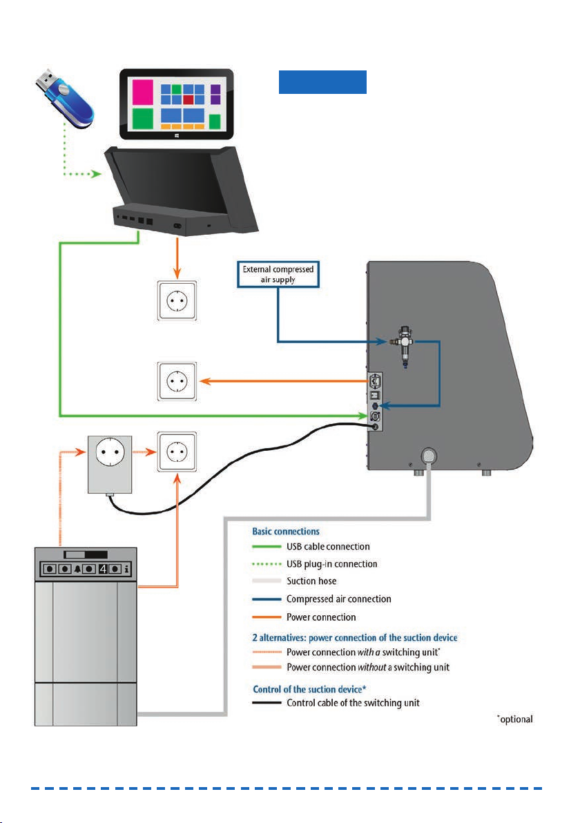
4.3 Machine installation (scheme)
12
Damage to the machine due to incorrect
installation
➤ Carry out the installation in the given order.
➤ Ensure to remove the transport lock before instal-
ling the manufacturing computer (➲ chapter 4.7).
NOTICE
Page 13
13
ENU
4.4 Installing the pneumatics
Risk of injuries through leaking compressed
air and lashing pneumatic hoses
Open or loose pneumatic connections can cause
severe injuries.
➤ Make sure that during installation and service
of the pneumatic hoses and of the service unit
compressed air is not running through the hoses
and connections.
➤ After installing the pneumatic hoses but before
running compressed air through the hoses and
connectors, check if the hoses are securely
inserted into the correct connectors and are not
damaged.
➤ Do not run compressed air through damaged
hoses and connectors.
The spindle may suffer bearing damage and
electrical damage if the compressed air is
contaminated
The incoming compressed air must be dry and oil-
free according to ISO 8573-1 because the service
unit only serves as an indicator for contaminated
air.
Air purity according to ISO 8573-1
Solid particles, Class 3,
Filtration degree better than 5 µm for solid particles
Water content, Class 4,
Maximum pressure dew point +3 °C
Residual oil content, Class 3,
Maximum oil content: 1 mg/m
3
➤ Ensure that the compressed air meets the above
requirements.
➤ Connect the machine to the compressed air
supply only via the provided service unit.
The spindle requires compressed air for the
following tasks:
• For the opening and closing of the collet chuck
during tool change.
• For the sealing air which prevents foreign bodies
from entering the spindle.
Air consumption of the machine:
• approx. 40 l/min at 6 bar
• approx. 50 l/min at 8 bar
WARNING
NOTICE
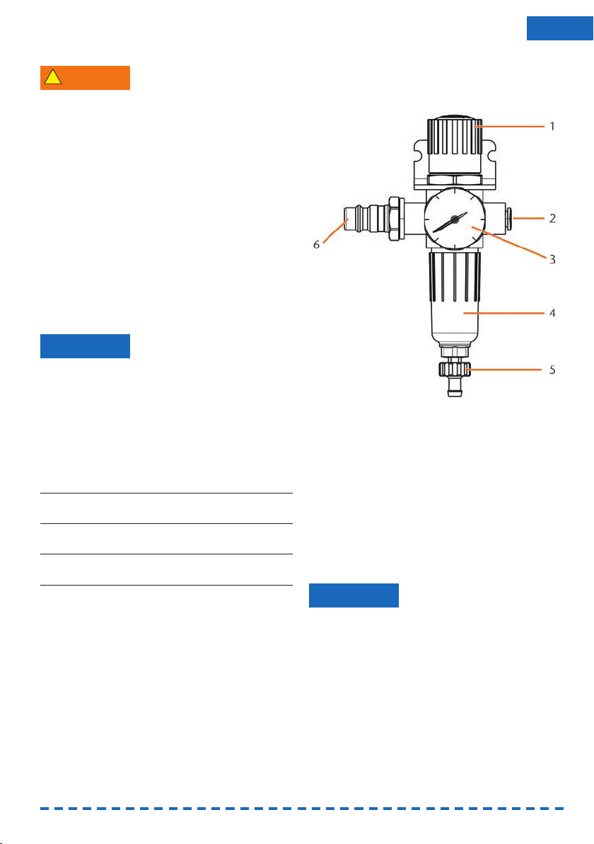
4.4.1 Overview service unit
Via the service unit you connect the CNC machine to
your compressed air supply and regulate the incoming pressure for the machine.
Fig. 8: The service unit:
Regulation and checking the air pressure
1 Rotary knob for pressure regulation
2 Pneumatic connection to the machine (ø 6 mm)
3 Manometer for monitoring the outgoing pressure
4 Water separator
5 Discharging screw
6 Pneumatic connection for external
compressed air supply
4.4.2 Mounting the service unit
on the CNC machine
Failure of the water separator caused by a
wrong alignment of the service unit
The service unit must always be mounted in an
upright position because otherwise the water
separator will not work.
➤ Mount the service unit in an upright position
(➲ Fig. 8). On the left side of the CNC machine
are two drilled holes which you can use to mount
the service unit on the machine.
NOTICE
!
Page 14

14
M1. Remove the two blind screws in the drilled holes.
M2. Mount the service units with the provided lens
head screws in an upright position.
Fig. 9: Mounting the service unit on the machine
4.4.3 Installing the pneumatic hoses
to the service unit
Fig. 10: Installation of the service unit (scheme)
M1. Close the external compressed air supply valve.
M2. Use the provided pneumatic hose to connect the
right pneumatic connection of the service unit
[Fig. 8, 2] with the pneumatic connection of the
machine.
M3. Connect the external compressed air supply with
the left pneumatic connection of the service unit
[Fig. 8, 6].
M4. Check the installation carefully for errors and
damage. Do not run compressed air through
damaged or loose hoses and connections!
M5. Open the external compressed air supply.
M6.Check the air pressure on the manometer
[Fig. 8, 3]. If it does not lie between 6 bar and
8 bar, adjust it with the service unit (➲ chapter
4.4.4)
4.4.4 Adjusting the air pressure with
the service unit
Setting the air pressure is only necessary if the air
pressure shown by the manometer does not lie
between 6 bar and 8 bar.
M1. Check if the service unit is correctly connected
to the machine and the compressed air supply
(➲ chapter 4.4.2 onwards).
M2. Pull the rotary knob on top of the service unit
slightly upwards.
M3. Turn the rotary knob in the desired direction until
the pressure lies between 6 bar and 8 bar
(recommended: 7 bar):
• Turning it towards “+“ you increase the
pressure
• Turning it towards “–“ you decrease it
M4. Push the rotary knob down again.
➡ The knob is locked and cannot be changed
inadvertently.
Fig. 11: Setting the air pressure
4.5 Installing the air extraction system
How the air extraction system works:
➲ chapter 3.5
Available components of the air extraction system:
• Suction device including suction hose
•
Switching unit for switching the suction device
on and off via the CNC machine
• Hose connection for suction hose: if the suction
hose does not fit into the machine
Which components are required and how you can
combine them is listed in the following table.
Page 15

You obtain the switching unit via customer service if
necessary.
4.5.1 Requirements for the suction
device
➤ Use a suction device with the following
properties
only:
• Designed for the commercial use in the
dental sector
• Equipped with a filter of the filter class M
• Suitable for the operating site of the CNC
machine
• Equipped with safety devices which protect
you from static discharges (e. g. through an
anti-static suction hose)
• Minimum extraction capacity: 2500 l/min
4.5.2 Absauggerät anschließen
➤ Before the installation of the suction device read
the documentation for the device and have the
documentation always ready at hand.
M1. Check if the connection of the suction hose has
an outer diameter of 45 mm. If the diameter is
different, use the optional hose connection
(➲ chapter 4.5.3.)
M2. Insert the suction hose of the suction device into
the opening for the air extraction of the CNC
machine. Make sure that the suction hose is
firmly connected.
Fig. 12: Inserting the suction hose into the machine
Component Source Required? Prerequisite
Suction device Customer service,
specialist dealers
Yes –
Switching device Customer
service
Nein –
Hose connection Customer
service
If the suction
hose does
not fit
Ask customer
service
M3. If you want the machine to automatically switch
the suction device on and off, install the
switching unit (➲ chapter 4.5.4. If you require a
switching unit, contact customer service.
M4. Continue with the installation of the suction devi-
ce as described in the documentation for the
device.
4.5.3 Connecting the suction hose with
the optional hose connection
If you can connect the suction hose of your
suction device directly to the CNC machine, you
do not need the hose connection.
M1. Obtain the hose connection via customer ser-
vice.
M2. Turn the thread of the hose connection counter-
clockwise until the connection is completely
open. If the thread gets detached from the hose
connection, place it onto the connection again
and turn it clockwise once so that it is screwed
to the connection again.
M3.
Insert the suction hose of the suction device
completely into the hose connection on the side
of the thread.
Abb. 13: Inserting the suction hose
into the hose connection
M4. Turn the thread of the hose connector clockwise
up to the stop.
➡ The suction hose is firmly attached to the hose
connection.
M5. Insert the hose connection into the opening for
the air extraction system of the machine. Ensure
it is firmly connected.
15
ENU
Page 16

Fig. 14: Inserting the hose connection into
the opening for the air extraction system
➡ The installation of the suction hose with the
optional hose connection is complete.
4.5.4 Installing the switching unit
M1. Connect the power cable of the suction device to
the switching unit.
M2. Connect the control cable of the switching unit
to the switching output at the connection panel
of the CNC machine.
M3. Plug the switching unit into a power socket.
Fig. 15: Connecting the switching unit to
the suction device and the machine
4.6 Establishing the electric connection
Damaging of the machine through heavy
voltage fluctuations
Heavy voltage fluctuations can disrupt the control
unit and can cause system failure.
➤ Plug the machine’s power cord in a dedicated
circuit current or ensure that no devices are
conn ected that can cause heavy voltage fluctuation when switched on.
NOTICE
Damaging of the machine if the transport lock
and the manufacturing computer are installed
When you connect the machine to the electrical
source and the manufacturing computer is connected, the machine starts referencing. During this
process, the transport lock which is installed at delivery can damage the mechanics of the machine.
➤ Do not connect the machine to the electrical
source if the manufacturing computer and the
transport lock are installed.
➤ If the transport lock is installed, disconnect the
USB connector between the machine and the
manufacturing computer before connecting the
machine to the electrical source.
M1. Plug the provided power cord into the power
connection at the connection panel of the CNC
machine.
M2. Put the plug of the cord into a socket that is pro-
tected by a Residual Current Device/Ground
Fault Circuit Interrupter.
4.7 Removing the transport lock
Before operating the machine for the first time, you
must remove the transport lock. The transport lock
prevents the spindle from getting damaged during
transport.
M1. Disconnect the USB connector between the ma -
chine and the manufacturing computer.
M2. Connect the machine to the electrical source.
M3. Switch on the machine via the main power
switch.
Fig. 16: Turning on the main power switch
M4. Open the front cover.
NOTICE
16
Page 17

Fig. 17: Removing the transport lock
1 Upper part of the transport lock
2 Bottom part of the transport lock
M5. Carefully pull the bottom part of the transport
lock (2) towards you and out of the working
chamber.
M6. Carefully lift the upper part of the transport lock
(1) out of the workpiece holder. Pull it towards
you and out of the working chamber.
M7. Clean the working chamber from parts of the
transport lock that may have broken off.
M8. Store the transport lock safely to use it for future
transports.
4.8 Connecting the manufacturing
computer
The transport lock must not be installed when
you connect the manufacturing computer to the
machine (➲ chapter 4.7).
M1. Switch on the machine.
M2. Close the front cover.
M3.
Start the manufacturing computer.
M4. Use the provided USB cable to connect a USB
port of your computer or docking station with
the connection panel of your CNC machine.
M5. Insert the dongle into a USB port of the manu-
facturing computer or docking station.
S6. Install the newest version of FINOCAM and
FINOCNC that is released for the machine. For
more information on this, read the documenta -
tion for the applications.
S7. Start FINOCNC and click on the de -
picted icon in the icon bar.
S8. Click on the depicted icon in the lower
icon bar.
➡ The application settings view displays.
S9. Click on the depicted icon beside the
text Port number.
➡ FINOCNC will try to establish a connection to the
CNC machine. If this is successful, the application will display the port number beside the icon
and the machine references.
The machine will not reference if the front cover
is open.
M10.If the front cover was open at step S9, close it. If
the machine does not reference as a result, quit
FINOCNC and restart the application.
M11.If FINOCNC did not determine the port number,
read how to determine the port number manually
in the documentation for the application.
4.9 Testing the machine
After the first installation or after a re-installation, for
example after a transport, you should test the basic
functions of the machine.
M1. Switch on the machine.
M2. Close the front cover.
➡ The machine starts up. The working chamber is
illuminated in white.
M3. Open the compressed air supply valve.
S4. Start the manufacturing computer and start
FINOCNC.
➡ The machine will reference and the working
chamber will illuminate in green. The machine is
now in
default position
.
S5. In the upper icon bar, click on the
depicted icon.
M6. Switch on the suction device and select the
necessary extraction level.
S7. If the machine controls the suction
device via a switching unit, click on the
depicted icon.
➡ The suction device is operating and a vacuum
develops in the working chamber.
M8. With the value bars and icons depicted below,
verify that the compressed air and the vacuum in
the working chamber are sufficient.
17
ENU
Page 18

18
➡ The icons display in blue when the compressed
air and the vacuum are sufficient.
Fig. 18: Top: Value bar and icon for compressed air
Bottom: Value bar and icon for the vacuum
S9. Move the spindle to the cleaning posi-
tion by clicking on the depicted icon.
➡ The spindle should move through the working
chamber at constant speed.
S10. Move the spindle from the cleaning
position back to the default position by
clicking on the depicted icon.
➡ The spindle moves to the default position at
constant speed.
S11. If the machine controls the suction devi-
ce, click on the depicted icon.
M12.If you control the suction device manually,
switch it off. The suction device stops operating.
M13.Open and close the front cover.
➡ The front cover can be opened and closed
easily.
M14.If a result did not occur as described, check the
following depending on the error:
• The USB connection & USB driver installation
(➲ chapter 4.8 & documentation for the manu-
facturing software)
• The compressed air supply (➲ chapter 4.4)
• The set extraction capacity of the suction device
• The installation of the air extraction system
(➲ chapter 4.5)
M15.If you cannot solve a problem that occurred,
contact customer service.
5. Running the machine
5.1 Starting up the machine
M1. Close the front cover.
M2. Switch on the machine and the manufacturing
computer.
➡ The machine and manufacturing computer start
up. When the machine has started up, the working chamber is illuminated in white.
M3. If machine controls the suction device, switch on
the device and select the necessary extraction
level.
➡ The suction device is not running.
If you control your suction device manually, you
switch on the device immediately before job
execution.
S4. Start FINOCNC.
➡ The machine references. Afterwards the working
chamber is illuminated in green. The machine is
now ready for use.
The machine will not reference if the front cover
is open.
M5. If the working chamber is illuminated in red,
switch the machine off and on again. If the wor-
king chamber is still illuminated in red, contact
customer service.
M6. If the front cover was open at step S4, close it.
S7.
If the machine does not reference as a result,
quit FINOCNC and restart the application.
5.2 Job execution overview
Damaging of the machine when using
damaged tools or workpieces
If tools or workpieces are damaged, parts can break
off and damage the machine during job execution.
➤ Check the workpieces and tools thoroughly for
damage before every job execution.
Carrying out a typical job with the FINOCAM A5 is as
follows:
1. Create a job in FINOCAM
2. Insert the tools into the machine
3. Insert the workpieces into the machine
4. Execute the job in FINOCNC
The steps in the manufacturing software are described in the corresponding documentation. The following text describes how to perform manual work with
the CNC machine.
NOTICE
Page 19

19
ENU
5.3 Inserting/changing tools
Damaging of the spindle or the tool positions
if you use improper tools
Improper tools can damage the collet chuck of the
spindle and/or the tool positions.
➤ Only use tools with a sufficiently large chamfer
at the tool shank.
➤ Install a retaining ring as a stop ring according to
DIN 471-A3.
➤ Only insert tools with a maximum diameter of
3 mm at the thickest part into the collet chuck.
➤ Only insert tools with a maximum cutting edge
diameter of 2.6 mm into the tool changer.
We recommend original tools as they are desig-
ned especially for the designated jobs.
You can insert up to 16 tools into the tool changer.
The machine can change tools automatically during
machining so that it executes jobs without your interference.
Fig. 19: Tool changer positions in the working chamber of
the machine (marked orange)
You can equip the tool changer in two ways:
• Via the spindle – you insert a tool into the collet
chuck and the spindle will deposit the tool in the
tool changer. This function is described in the
documentation for the manufacturing software.
• By inserting the tools into the tool changer
manually. This is described below.
You insert the tools manually as follows:
S1. Start FINOCNC.
S2. Call up the job execution view and select the job
that you want to execute from the job list.
➡ FINOCNC displays the tools that are assigned to
the job in the lower part of the application win -
dow.
M3. Open the front cover.
NOTICE
M4. Insert the tools into the tool positions of the tool
changer:
• Insert the tools straight into the tool positions
and push them in until the ring touches the
rubber (➲ Fig. 20).
• The positions of the tools in the tool changer
must match the tool positions in FINOCNC
(➲ Fig. 21).
If the positions of the tools in the tool changer
do not match the tool positions in FINOCNC, the
machine will use the wrong tool(s) during job
execution and the job result will become unusable.
Fig. 20: Inserting tools straight into the tool position
Page 20

Fig. 21: Top: tool positions 1 – 16 in the tool changer
Bottom: tool positions 1 – 16 in FINOCNC
5.4 Inserting and removing workpieces
On delivery, your FINOCAM A5 processes blanks
with a diameter of 98.5 mm.
5.4.1 Inserting blanks
You put blanks into the workpiece holder and immobilize them with a fixing disc.
Fig. 22: The fixing disc (blue) is attached to the workpiece
holder (grey) with 4 screws (orange)
M1. Open the front cover.
M2. Unscrew the 4 screws which attach the fixing
disc to the workpiece holder.
M3. Remove the fixing disc and the blank in the
workpiece holder (if any).
M4. Place the blank into the workpiece holder.
Fig. 23: Placing the blank into the workpiece holder
M5. Place the fixing disc onto the workpiece holder
on top of the blank.
20
Page 21

21
ENU
M6. Screw down the fixing disc with the screws you
unscrewed in step M2.
Tighten the screws firmly. If workpieces move
or vibrate during processing, the result may
become unusable.
Fig. 24: Attaching the blank with the fixing disc
5.4.2 Removing blanks
M To remove a blank, unscrew the 4 screws of the
fixing disc and remove the fixing disc and the
blank.
5.4.3 Mounting the FINOCAM block
holder
You can obtain the optional FINOCAM block
holder via customer service.
The FINOCAM block holder allows you to grind workpieces in block shape with your FINOCAM A5. You
can attach the FINOCAM block holder to the built-in
workpiece holder and then secure the blocks into the
block holder.
Fig. 24: The FINOCAM block holder for the FINOCAM A5
1 Positioning aid for the FINOCAM block holder
2 Positioning pins for blocks
3 Drilled holes for inserting blocks
4 Fixing pins for blocks
M1. Open the front cover.
M2. Remove the fixing disc and blank from the wor-
king chamber (➲ chapter 5.4.1, page 21).
M3. Place the FINOCAM block holder so that the 2
positioning aids (1) lie in the
left
outer roundings
of the workpiece holder (➲ Fig. 25). Hold the
FINOCAM block holder in place with one hand.
Fig. 25: Positioning the FINOCAM block holder
Page 22

M3. Insert the shaft of the block into the desired
position in the FINOCAM block holder until it is
completely and firmly seated.
M4. Fixate the block with the corresponding fixing
pin. Tighten the pin firmly.
Fig. 28: Inserting blocks into the FINOCAM block holder
5.5 Executing jobs
Do not move the machine during job execution,
otherwise the results may become imprecise.
M1. Make sure that the following requirements are
met before job execution:
• You created the job that you want to execute in
FINOCAM and transferred it to FINOCNC.
•
All required tools are assigned to the job in
FINOCNC.
• The required tools are in the right positions in
the tool changer of the machine.
• All required workpieces of the correct material
are inserted.
• The compressed air supply is set correctly.
M2. Close the front cover.
M3. Switch on the suction device and set it to the
required level.
S4. Start the job execution in FINOCNC.
➡ The CNC machine begins with the job execution.
The working chamber is illuminated in blue.
5.6 Interrupting the job execution
S Click on the depicted icon to interrupt
the job execution. The icon only displays during job operation.
22
M4. With the other hand, lay the fixing disc above the
FINOCAM block holder into the workpiece holder
and screw it down with the provided torque
wrench.
➡ The FINOCAM block holder is ready for use.
Fig. 26: Immobilizing the FINOCAM block holder
with the fixing disc
5.4.4 Attaching blocks into the
FINOCAM block holder
You can attach up to 3 blocks with round shafts into
the FINOCAM block holder.
The material, number and position of the blocks
must correspond to the job in DentalCAM.
M1. Loosen the fixing pins at the position where you
want to insert the blocks.
M2. Position the block so that the positioning pin at
the FINOCAM block holder lies in the groove in
the block shaft.
Fig. 27: Positioning pin (left marking) must lie
in the groove in the shaft (right marking)
Page 23

5.7.3 How to proceed in case of a tool
breakage
If a tool breaks during machining, the machine will
not recognize this immediately and the spindle will
continue until the next tool change. Only upon measuring the broken tool will the job execution be cancelled and FINOCNC will display a corresponding
message.
A tool breakage can be caused by the following:
• The tool was damaged or worn.
• The tool was put into the wrong tool changer
position or was inserted into the spindle manually at the wrong time. As a consequence, it was
not suitable for the processing step.
• The distribution of the objects in the workpiece
(“nesting”) was not sufficiently adapted to the
material.
M1. Open the front cover.
M2. Remove all parts of the broken tool from the
working chamber.
M3. If the spindle picked up the tool from the tool
changer, check if the tool was inserted into the
correct position. Insert a spare tool into the correct position in the tool changer (➲ chapter 5.3).
M4. If you inserted the tool into the collet chuck
manually, check if the broken tool corresponds
to the initial tool type in which FINOCNC prompted. Have a correct spare tool ready.
M5. Close the front cover and execute the job again.
If tools break regularly, you can find additional
information in the chapter on troubleshooting
(➲ chapter 8).
23
ENU
5.7 Operation interruption or abortion
of job execution
An operation interruption can occur because the
compressed air supply or the vacuum in the working
chamber is not sufficient. An
interrupted
job will
normally be resumed automatically after the error is
corrected.
The job execution is
aborted
in the following cases:
• In case of a machine malfunction
• In case of a tool breakage
• In case of a power failure
If a job was
aborted
, you have to execute it again in
FINOCNC.
5.7.1 How to proceed in case of
an operation interruption
If the job execution was interrupted, FINOCNC
displays a corresponding message.
M1. If FINOCNC prompts that the compressed air is
insufficient, check the following:
• The manometer of the service unit
The installation of the pneumatic hoses
• Your compressor
M2. If FINOCNC prompts that the vacuum in the wor-
king chamber is insufficient, check the suc tion
hose and your suction device.
You will find additional information in the chapter
on troubleshooting (➲ chapter 8).
5.7.2 How to proceed in case of a
machine malfunction
A machine malfunction is recognized by the internal
control unit in case of a critical event. The working
chamber will be illuminated in red. FINOCNC
displays the error message and error code that was
sent by the control unit.
M1. Disconnect the machine from the electrical
source and prevent it from being restarted.
M2. Record the error message and error code that is
displayed in FINOCNC.
M3.Contact customer service. Have the error
message and error code from FINOCNC readily
available.
M4.To remove a workpiece from the working
chamber, unlock the front cover with the key for
emergency release (➲ chapter 5.8).
Page 24

5.7.4 Procedure in case of a power
failure
As long as the machine is not powered, the front
cover will remain locked.
➤ After a short power failure turn on the machine
again and follow the on-screen prompts so that
the machine can reference.
➤ In case of a longer power failure use the provi-
ded key for the emergency release of the front
cover.
5.8 Not-Entriegelung der Frontklappe
➤ Only use the emergency release of the front
cover to remove a workpiece from the working
chamber if the front cover is permanently locked.
Crushing hazard and cutting injuries while
running the machine with the front cover open
If the safety lock is not reactivated after the emergency release, the user will be able to operate the
machine with the front cover open. In this case the
front cover will not protect the user from bruises
caused by machine movements and from cutting
injuries caused by the rotating tool.
➤ Activate the safety interlock immediately after
completing your work in the working chamber.
➤ Never operate the machine with the front cover
open. h Perform the emergency release only if
you are authorised to do so and if you have
received training on its usage.
➤ Store the key for the emergency release in a
place where only authorised persons can access
it.
➤ Report every emergency release to customer
service.
Cutting injuries when touching a rotating tool
If a power failure or a machine malfunction occurs
during processing, the spindle including the inserted
tool keeps rotating. If you touch the rotating tool,
you will suffer from cutting injuries.
➤ Wait until the spindle has stopped rotating befo-
re carrying out an emergency release.
There is an opening for the emergency release at the
right side of the machine.
WARNING
CAUTION
Fig. 25: Opening for the emergency release
M1. Switch off the machine at the main power switch
and disconnect the machine from any electrical
source and the compressed air supply.
M2. Remove the protective cap from the emergency
release opening (➲ Fig. 26, top).
M3. Insert the key for the emergency release of the
front cover through the opening (➲ Fig. 26,
middle).
M4. Deactivate the safety interlock of the front cover
by turning the key counter-clockwise by 90°
(➲ Fig. 26, bottom).
➡ You can open the front cover.
M5. Carry out your work in the working chamber.
M6. Close the front cover.
M7. Reactivate the safety interlock of the front cover
by turning the key for the emergency release
clockwise by 90° (➲ Fig. 26, bottom).
M8. Check if the front cover actually is locked.
➡ If you can still open the front cover, repeat the
steps M6–M8.
24
!
!
Page 25

Fig. 26: Using the key for the emergency release
Top: Remove cap
Middle: Insert key
Bottom: Turn the key
M9. Close the opening for the emergency release
again with the protective cap.
6. Machine maintenance and cleaning
6.1 Definition of wear parts
The CNC machine and the extra equipment are warranted for a period of 24 months or 2000 operating
hours, whatever comes first. The warranty covers
defects in materials or fabrication as long as the
regulations for using the machine in all documents
are followed.
Of course, the warranty also covers wear parts as
long as their failure cannot be attributed to the
function-related abrasion. The wear parts that are
mentioned below can already wear down within the
warranty period due to their normal function. The
average useful life of the wear parts can be seen in
the following table.
Use these values to determine operating costs, to
plan your spare part stock as well as to create individual maintenance and service plans.
25
ENU
Page 26

26
6.2 Maintenance table
Task Recommended interval Procedure/Parts Spare part illustration
Cleaning the working
chamber & the measuring
key (➲ chapter 6.4)
Cleaning the collet chuck
(➲ chapter 6.5)
Checking the hoses,
cables & connections
(➲ chapter 6.6)
Cleaning the housing &
accessories container
(➲ chapter 6.7)
Service unit:
a) Checking for
contamination
b) Cleaning/exchanging
the filter cartridge
(➲ chapter 6.8)
Exchanging the main fuse
(➲ chapter 6.9)
Calibrating the axes
(➲ chapter 6.10)
Inspection by a service
technician (➲ chapter 6.3)
Wear parts
Exchanging wear parts
Exchanging the tool
changer inserts
(➲ chapter 6.11)
Exchanging the collet chuck
Exchanging the spindle
bearings (requires spindle
exchange by service
technician)
1 x per day, more often if the
chamber is very dirty
1 x per week, in case of
rotational imperfections,
in case of bad machining
results
1x per week
As necessary
a) Necessarily every day
b) In case of visible contami-
nation or every 2 years
In case of a defective fuse
in the power supply of the
machine
Only if necessary
After 2000 operating hours*
or every 2 years*
Average useful life
After 500 operating hours*
After 1000 operating hours*
After 2000 operating hours*
or every 2 years*
Vacuum cleaner, brush,
dry cloth, never use
compressed air
Spindle service set
Visual inspection
Cloth, water,
possibly a mild cleaner
A new filter cartridge
if necessary
Replacement fuse of the
type T6,3A L250V
Calibration specimen,
micrometre, calibration tool
Procedure/Parts
Replacement inserts,
drill for drilling the tool
positions, screwdriver
Performed by service
technician
* These are recommendation guidelines. Depending on the processing material and how well the machine is cleaned, these values may differ.
Spare part illustration
Page 27

6.3 Inspection
We recommend having a service technician perform
an inspection regularly.
➤ In addition, have an inspection carried out when -
ever the machine is being repaired.
6.4 Cleaning the working chamber and
measuring key
Breathing difficulties caused by processing
dust
Processing dust that gets into your lungs can cause
breathing difficulties.
➤ Clean the machine only if the air extraction
system is properly installed and activated.
➤ Wear a face mask of class FFP2 during the entire
cleaning.
Damaging of the linear guides or the spindle
when cleaning with compressed air
If you clean the working chamber with compressed
air, material chips can reach the linear guides or the
spindle bearings.
➤ Clean the interior of the machine exclusively
with a vacuum cleaner, a brush and a cloth and
never with compressed air.
M1. Have ready:
• A vacuum cleaner
•A
dry
cloth
•A
mild
cleaner (optional)
• A wet brush
M2. Switch on the machine and start FINOCNC.
S3. In the upper icon bar, click on the
depicted icon.
S4. Move the spindle to the cleaning posi-
tion by clicking on the depicted icon.
➡ The spindle will move to the cleaning position
and the sealing air will be activated.
M5. Open the front cover.
M6. Suck up the coarse dirt in the working chamber
with the vacuum cleaner.
M7. Clean the whole interior thoroughly with the dry
cloth. Use a mild cleaner if necessary.
CAUTION
NOTICE
M8. Thoroughly clean the workpiece holder including
all screws, pins and clamping mechanisms as
well as all openings from the processing dust.
M9. Clean the measuring key with a brush.
Fig. 27: Measuring key on top of the tool changer
(marked orange)
M10.Close the front cover of the machine.
S11. Move the spindle from the cleaning
po si tion back to the default position by
clicking the depicted icon.
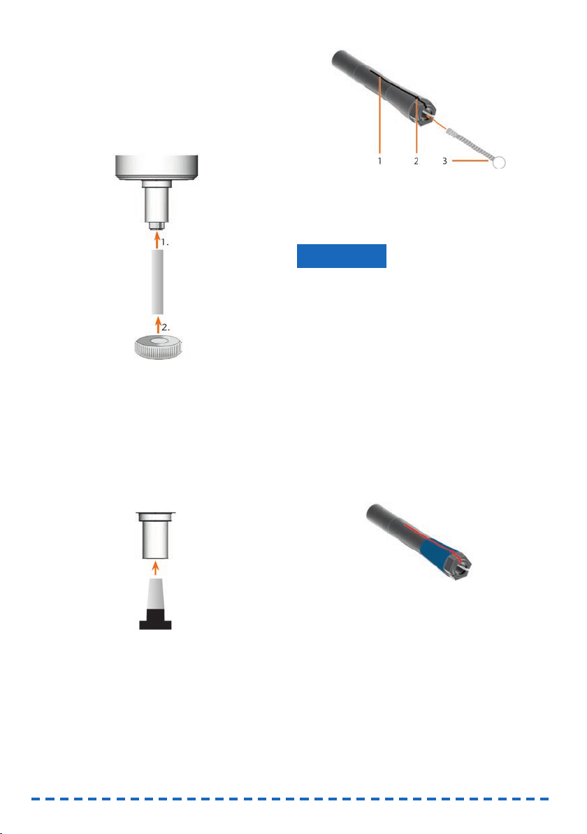
6.5 Cleaning the collet chuck
Damaging of the spindle when cleaning with
compressed air
If you clean the collet chuck with compressed air, the
spindle bearings may get damaged.
➤ Clean the collet chuck exclusively with the
appropriate service set.
Fig. 28: Components of the spindle service set
1 Collet grease
2 Cleaning brush
3 Knurled nut
4 Cleaning cone
NOTICE
27
ENU
!
Page 28
M1. Close the front cover of the machine.
S2. Open the collet chuck with the “Release tool”
function of FINOCNC and remove the tool from
the spindle if necessary.
M3. Insert the measuring pin into the collet chuck
and keep holding it with one hand. With the
other hand put the knurled nut to the spindle.
Fig. 29: Unscrewing the collet chuck
M4. Loosen the collet chuck with the knurled nut and
unscrew the collet chuck with your hand or with
the knurled nut.
M5.Remove the measuring pin from the collet
chuck. Then put it aside within reach together
with the knurled nut.
M6. Clean the inner cone of the spindle with the
cleaning cone of the service set.
Fig. 30: Cleaning the inner cone of the spindle
M7. Clean the collet chuck with the brush of the
service set. Make sure that the 3 buffers in the
collet chuck do not fall out during cleaning.
Fig. 31: Cleaning the collet chuck
1 Longitudinal slot
2 Buffer
3 Cleaning brush
Damaging of the spindle when using the wrong
grease or applying the grease in a wrong way
If you use grease that is unsuitable for the spindle or
if grease gets into the longitudinal slots of the collet
chuck, the spindle may get damaged.
➤ Ensure that no grease gets into the longitudinal
slots of the collet chuck.
➤ Only use a very small, about pinhead-size
amount of the grease.
➤ Only use the provided collet grease of the ser-
vice set.
M8. Put a small amount of the collet grease on the
index finger and smear it with the thumb.
M9. Apply the smeared collet grease to the flanks of
the collet chuck.
Fig. 32: Greasing the collet chuck; surface to grease is
marked in blue; Slot that may not be greased is
marked in red
M10.Insert the measuring pin into the collet chuck
with one hand and keep holding it. Screw the
collet chuck with the knurled nut in your other
hand
tightly
into the spindle.
In any case, turn the knurled nut up to the stop
so that the collet chuck is properly seated in the
spindle. Otherwise rotational imperfections can
occur during operation which will worsen your
processing results.
NOTICE
28
Page 29

29
ENU
M11.Remove the measuring pin from the collet chuck
and store it together with the other components
of the spindle service set.
M12.Close the front cover.
6.6 Checking the hoses, cables and
connections
M1. Disconnect the machine from the electrical sour-
ce and the compressed air supply.
M2. Check the hoses and cables that are connected
to the machine.
M3. In case of damages prevent the machine from
being restarted. Replace the damaged cables
and hoses immediately with original replace-
ment cables. Contact customer service.
M4. Verify all connections on the connection panel
(e.g. loose connections).
M5. Re-insert loose cables and hoses tightly into the
corresponding connections. In case of damaged
connections cease use of the machine immedia-
tely. Contact customer service.
6.7 Cleaning the housing
Damaging of the housing when using
a nonrecommended cleaner
If you use an unsuitable cleaner for cleaning the
machine housing, the surface or the adhesive foil can
get damaged.
➤ Avoid contact of the powder coating with alkaline
or acid substances. Especially metallic powders
show a highly sensitive reaction.
➤ Take care of the glued symbols so that they do
not peel off. The adhesive foil is especially sensi-
tive to rubbing and strong detergents.
➤ If the usage of a special cleaner is necessary to
eliminate certain dirt, we recommend checking
the suitability of the cleaner at a hidden place of
the part first.
M1. First, clean the powder coated surface with a
soft, dry cloth.
M2. If some dirt cannot be removed this way, moisten
the cloth. Use a pH neutral cleaner if necessary.
NOTICE
6.8 Checking the service unit
Damaging of the machine when compressed
air is contaminated
Compressed air that does not fulfil the guidelines for
purity according to ISO 8573-1 can damage the
machine.
➤ Check the water separator of the service unit
daily for contamination.
➤ Never use the machine if there is water, oil or
solid particles in the water separator.
6.8.1 Checking the water separator for
condensate
Condensate in the separator usually points to compressed air not being dry enough.
M1. Check if water, oil or solid particles piled up in
the water separator.
➡ In this case switch the machine off immediately
and proceed as follows:
M2. Check the compressed air supply and make sure
that the compressed air fulfils the requirements
for air purity according to ISO 8573-1. Do not use
the machine until the compressed air fulfils this
requirement!
M3. Drain the water separator by turning the dischar-
ging screw counter-clockwise.
➡ The condensate is blown out downwards under
pressure.
M4. Close the discharging screw again by turning it
clockwise.
Fig. 33: Opening/closing the discharging screw
at the service unit
NOTICE
Page 30

M4. Remove the defective fuse and replace it with a
new fuse of the type T6,3A L250V.
If you do not have a replacement fuse ready,
take the replacement fuse from the right side of
the fuse cover and put it into the left side of the
fuse cover.
M5. Remount the fuse cover.
6.10 Calibrating the axes
Deterioration of machining results caused by
an incorrect calibration
The machine is already calibrated at delivery. As
long as your machining results are without flaw, a
new calibration is not necessary. A calibration takes
much time and can deteriorate the machining results
in the worst case if it is not done correctly.
➤ In case of inaccurate machining results, try
adjusting the working conditions first: check the
fixation of the workpiece, the state of the tool or
of the processing material.
➤ Before calibrating the machine, contact custo-
mer service.
➤ Be very careful when measuring and entering
data during calibration. When in doubt, stop the
calibration.
With test and calibration specimens you can measure and, if possible, improve the machining results of
the CNC machine
The documentation for the manufacturing soft-
ware contains all information on calibrating the
machine. Therefore, you will only find infor mation specific to the FINOCAM A5 in this document.
Your FINOCAM A5 is delivered with a calibration set.
It contains the following parts:
•
Calibration blanks which you use
to mill calibration and test specimens
•
A tool for milling the calibration or
test specimens
• A micrometre for measuring the
machining precision
NOTICE
30
6.8.2 Exchanging/cleaning the
contaminated filter cartridge
You have to clean or exchange the filter cartridge in
the water separator in case of strong contamination.
A strongly contaminated cartridge can lead to a
pressure loss.
If the compressed air fulfils the requirements for air
purity according to ISO 8573-1, the filter cartridge
usually does not have to be changed.
➤ If the filter cartridge is contaminated, check the
purity of your compressed air.
You exchange or clean the filter cartridge as
follows:
M1. Disconnect the machine from the compressed
air supply.
M2.
Unscrew the bowl of the water separator.
M3. Untighten the filter screw below the filter cart -
ridge.
M4. Pull out the filter cartridge and clean it if neces-
sary.
A new filter cartridge is available as spare part
from customer service.
M5. Insert the new or cleaned filter cartridge and
reassemble the water separator.
6.9 Exchanging the main fuse
Only use fuse type T6,3A L250V as a replace-
ment fuse.
The internal power supply of the FINOCAM A5 has a
main fuse that is accessible from the outside and
can be replaced if necessary.
A new main fuse is available as spare part from
customer service.
M1. Turn off the machine at the main power switch
and dis- connect the machine from any electrical
source and the compressed air supply.
M2. Remove the power cord from the connection
panel.
M3.
Remove the cover of the fuse.
Fig. 34: Cover of the fuse (marked orange)
Page 31

31
ENU
Tool breakage or incorrect results caused by
loose screws
If the workpiece is screwed into the workpiece holder
too loosely, the measurement results may become
incorrect or the tool may break during calibration.
➤ Tighten the screws of the fixing disc firmly.
M1. Insert a calibration blank into the workpiece
holder.
S2. Mill the calibration/test specimen as described
in the documentation for the manufacturing
software.
➡ After milling the calibration/test specimen looks
as follows:
Fig. 35: A milled calibration/test specimen
for the FINOCAM A5
M3. Remove the calibration/test specimen from the
machine.
S4. Follow the instructions on calibration in the
documentation for the manufacturing software.
M5. After the calibration, remove the calibration tool
from the machine and keep all parts of the
calibration set for further use.
6.11 Replacing the tool changer inserts
When the tool changer inserts are worn, they should
be replaced. Afterwards you must drill the tool positions into the new inserts with the CNC machine.
• Your CNC machine comes with tool changer
inserts as spare parts and with the drill tool.
• Additional inserts and drill tools are available via
customer service.
NOTICE
➤ Always replace
both
inserts together even if only
one of the inserts is worn. The machine will
always drill the tool positions for
both
inserts.
The documentation for the manufacturing
software contains step-by-step instructions for
drilling the inserts. Below you find a description
of how to replace the tool changer inserts in the
machine.
M1.
Have 2 tool changer inserts ready as spare
parts.
M2. Open the front cover.
M3.
Remove all tools from the tool changer.
M4. Loosen the 4 screws on the upper side of the
tool changer and lift the cover (➲ Fig. 36).
M5. Remove the 2 existing tool changer inserts and
replace them with 2 new ones (➲ Fig. 37).
M6. Put the cover back onto the tool changer and
screw it down with the screws that you untightened in step M4.
S7. Follow the instructions in the documentation for
the manufacturing software and drill the tool
positions in the new inserts.
Fig. 36: Loosening the screws and lifting the cover
Page 32

Fig. 37: New tool changer inserts (right, without drill
positions) replace old inserts (left, with drill positions)
7. Disposal
We will dispose of the machine at no cost. The owner
will bear the costs for disassembly, packaging and
transport.
➤ Before sending in the machine for disposal,
contact customer service.
➤ If you dispose the machine yourself, abide by
the national and local laws of the disposal
location.
8. Troubleshooting
Danger to life due to improper troubleshooting
In case of improper troubleshooting, you may suffer
from severe or deadly injuries caused by, for example, electric shocks, axis and spindle movements,
loose pneumatic components and pneumatic hoses.
In addition, your machine may get damaged.
➤ Do not remove the housing of the machine.
➤ Before you check or run pneumatic hoses,
close the external compressed air supply valve.
➤ Before you check or run electric cables or
power connectors, disconnect the machine from
the electrical source and prevent it from being
restarted.
➤ Do not perform any troubleshooting while the
machine is operating.
➤ Wear safety gloves throughout the troubleshoo-
ting process.
DANGER
32
➤ If you are unsure of how to perform certain steps
during troubleshooting or cannot solve the
problems, abort the troubleshooting and contact
customer service.
Additional symbols in this chapter
Problem/question
Solution/answer
Frequently Asked Questions (FAQ)
The suction hose of my suction device
does not fit into the opening for the air
extraction system of the CNC machine.
Is the suction hose equipped with a hose connection?
M1. Unscrew the hose connection from the suction
hose.
M2. Try to insert the suction hose into the opening
for the air extraction system.
M3. If the suction hose still does not fit, contact
customer service and obtain a suitable hose
connection.
M4. Install the suitable hose connection to the suc -
tion hose.
➲ Chapter 4.5.3
Did the suction hose come without a hose
connection?
M1. Contact customer service and obtain a suitable
hose connection.
M2. Install the suitable hose connection to the suc -
tion hose.
➲ Chapter 4.5.3
I cannot open the front cover.
Is the machine operating? While the axes are
moving, the front cover stays locked.
M Wait until the machine has finished and the
working chamber lighting shines green.
Without electricity, the front cover remains
locked.
Has a power failure occurred at the installation
site of the machine?
M Depending on the duration of the power failure,
restart the machine or use the key for the emergency release.
➲ Chapter 5.7.4
!
Page 33

Is electricity available at the installation site of
the machine?
M1. If you have not removed the transport lock from
the working chamber yet, disconnect the machine from the manufacturing computer.
M2. Connect the machine to the electrical source
and switch it on via the main power switch.
M3. If the working chamber lighting does not illumi-
nate, check if the power cable is properly seated
in machine and to the power source.
M4. Try connecting the machine to a different socket.
➲ Chapter 3.2
I have installed all components, started
FINOCNC but the machine does not refe-
rence.
Is the front cover open? The machine does not
reference with the front cover open.
M Close the front cover.
Is the USB cable connected properly?
M Check if the USB cable is properly seated in the
connector and is undamaged. If possible, use
the provided cable.
Is the correct port specified in FINOCNC?
Without the correct port, the application will not
establish a connection with the machine.
S1. Start FINOCNC.
S2. Try to have the application determine the correct
port in the application settings.
S3. If the application cannot determine the correct
port, enter the port manually. For this, follow the
instructions in the documentation for the manu-
facturing software.
➲ Chapter 4.8
My machine does not execute any jobs alt-
hough FINOCNC displays that there is a
connection between the manufacturing
computer and the machine.
Is the front cover open? The machine does not
move the axes if the front cover is open.
M Close the front cover.
➲ Chapter 3.2
The machining results are not satisfactory
and/or tools keep breaking.
Do the tool positions in FINOCNC correspond to
the tools in the tool changer of the machine? If
not, the machine uses the wrong tools during job
execution.
S1. Call up the job execution view in FINOCNC.
S2. Compare the tool positions in the application to
the tools in the tool changer.
M3. Replace the wrong tools in the tool changer with
the correct ones.
➲ Chapter 5.3
Is the workpiece attached properly?
M Ensure that all screws, pins and clamping
mechanisms fixate the workpiece firmly.
➲ Chapter 5.4
Are the tool changer inserts worn?
M Exchange the tool changer inserts against new
ones.
➲ Chapter 6.11
Are screws, pins and clamping mechanisms as
well as the corresponding openings contamina-
ted by processing dust?
M Clean the mentioned components thoroughly.
➲ Chapter 6.4
Are the tools worn?
M Check the tools in the tool changer and
exchange the worn tools with new ones. Also
check the tool life values which are shown in
FINOCNC.
Do rings on the tools sit in the groove on the tool
shank?
M Check all tools and push rings that have moved
into the groove again.
Do the parameters of the job in FINOCAM cor-
respond to the parameters of the workpiece?
M Make sure that the following parameters of the
job and of the workpiece correspond to each
other and that they are suitable for the objects
that you want to machine:
• Material type
• Dimensions of the workpiece
• Indications (types) of the individual objects
33
ENU
Page 34

Do you use the newest version of the manufac turing software that is released for the FINOCAM
A5?
New versions often contain important optimiza -
tions.
S
Update the applications by clicking on
the depicted icon.
Alternatively, contact customer service.
Are the STL files of sufficient quality?
S1. Before you import STL files into the manufactu-
ring software, check their quality. Especially
consider the manufacturer information on wall
thickness and border thickness.
S2.
If necessary, adjust the settings of your scanner
and scan application.
Are the bars of the individual objects set
correctly?
S If you set bars, consider the corresponding
information in the documentation for FINOCAM.
Is the measuring key contaminated? This prevents a correct tool measurement.
M Clean the measuring key with a brush.
➲ Chapter 6.4
Is the collet chuck of the spindle contaminated
or is it loosely seated in the spindle?
M1. Clean the collet chuck with the provided spindle
service set.
M2. When you insert the collet chuck into the spind-
le, make sure that it is properly seated.
➲ Chapter 6.5
Did you calibrate the machine shortly before the
problems occurred or have their been any pro-
blems recently with the tool change?
M Contact customer service.
Did you exchange the collet chuck at the recom-
mended interval?
M Verify the recommended interval for exchanging
the collet chuck in the maintenance table and
exchange the collet chuck if necessary.
➲ Chapter 6.2
FINOCNC interrupts the job execution and
displays that the air pressure is too low.
You can resolve this problem while the job exe-
cution is interrupted. FINOCNC continues the
job as soon as the air pressure is sufficient
again.
Is the service unit properly set?
M Set the air pressure at the service unit to a value
between 6 bar and 8 bar (recommended: 7 bar).
➲ Chapter 4.4.4
Is the error caused by the external compressed
air supply?
M1. Close the external compressed air supply valve.
M2. Check if all pneumatic hoses are properly seated
in their connections and are undamaged.
M3. Check if your compressor is switched on and set
correctly.
M4. Check if all effected valves of your compressed
air system are open.
Does the air pressure fluctuate significantly
according to the service unit so that the job execution is interrupted and continued frequently?
M1. Check if your compressor can permanently
generate at least 6 bar air pressure with a volume flow of 40 l/min.
Not every compressor is designed for commer-
cial use with dental machines.
M2. If necessary, replace your compressor with one
that meets the above recommendations.
➲ Chapter 4.4
FINOCNC interrupts the job execution and
displays that the vacuum is too low.
You can resolve this problem while the job exe-
cution is interrupted. FINOCNC continues the
job as soon as the vacuum is sufficient again.
Is the suction device switched on and operating?
M1. Switch on the suction device.
M2. Check if the suction hose is properly seated in
the opening at the machine and is undamaged.
M3. If the machine controls the suction device,
check if the switching unit is properly installed.
Try operating the suction device without the
switching unit.
➲ Chapter 4.5
34
Page 35

Is the suction device set correctly?
M Set the extraction level higher until FINOCNC
continues the job.
➲ Chapter 4.5
Is the filter or container of the suction device
full?
M If necessary, insert an empty filter into the suc -
tion device or empty the container.
➲ Documentation of the suction device
Does the suction device have an automatic
tapping function?
M Choose a shorter tapping interval.
➲ Documentation of the suction device
I have exchanged the tool changer inserts
and now there are no holes for the tools
anymore.
Tool changer inserts are delivered without drilled
holes for tools. You drill them with the CNC
machine.
S Drill the tool positions into the inserts with
FINOCNC.
➲ Chapter 6.11
35
ENU
Page 36

36
9. Index
A
Air extraction system ....................................8, 14
Air purity ........................................................13
Axis calibration ...............................................28
B
Blanks, insert/remove......................................20
C
Calibration .....................................................28
Cleaning ....................................................6, 23
Collet chuck
clean .......................................................25
Colours of working chamber lighting....................7
Compressed air
check.......................................................17
consumption .............................................13
install.......................................................13
requirements.............................................13
set via service unit .....................................14
Condensate....................................................27
D
Discharging screw...........................................27
Disposal ........................................................30
E
Emergency release of the front cover.................22
F
FAQ ..............................................................30
Filter cartridge................................................28
Flow rate, check .............................................32
Front cover emergency release .........................22
Fuse, exchange ..............................................28
H
Hose connection..............................................15
Housing, cleaning ...........................................27
I
Inspection......................................................25
Installation site ................................................11
Installing the machine .......................................11
Intended use....................................................5
J
Job execution, start .........................................21
K
Key for emergency release ...............................22
M
Machine malfunction .......................................22
Main fuse, exchange .......................................28
Maintenance................................................6,23
table .......................................................24
Manufacturing software. ....................................9
Measuring key ................................................25
O
Operation .......................................................21
Operation interruption ......................................21
P
Power failure ..................................................22
Processing, start .............................................21
R
Regulations .....................................................5
Room temperature............................................11
Rotational axes...............................................28
S
Safety instructions............................................3
Safety interlock ..............................................22
Scope of delivery .............................................11
Service unit
check ......................................................27
install pneumatic hoses ..............................14
mount to the CNC machine .........................13
overview ...................................................13
set air pressure .........................................14
Sound emission................................................9
Page 37

37
ENU
Spindle........................................................6, 9
Spindle service set..........................................25
Storage...........................................................8
Suction device
data cable.................................................15
hose connection ........................................15
installation ................................................15
requirements.............................................15
switching unit............................................16
Switching unit ................................................16
T
Technical data..................................................9
Testing the machine.........................................17
Tool breakage.................................................22
Tool changer ...............................................9, 19
Tool changer positions .....................................19
Tools, insert/exchange .....................................19
Transport.........................................................6
Troubleshooting..............................................30
V
Vacuum, check................................................17
W
Warranty........................................................24
Water separator..............................................27
Working chamber
cleaning...................................................25
lighting......................................................7
Page 38

FINO GmbH
Mangelsfeld 18
D-97708 Bad Bocklet
Tel +49- 97 08-90 94 20
Fax +49- 97 08-90 94 21
info@fino.com · www.fino.com
Page 39

Page 40

Version 1/2016. Read the User Manual prior to commencing work!
1. About these instructions for use 4
2. User interface elements 5
3. Installation & update 7
• Checking the system requirements • Preparing the Installation / udapte
• Starting the installation / upate • Using the update feature • Viewing the release notes
4. FINOCAM
4 Introduction 15
• The concept of FINOCAM • Intended use
5. The user interface 16
6. Starting and setting up FINOCAM 17
• Adjusting the general settings • Specifying the processing settings
• Specifying the data transfer settings
7. Creating workpieces and selecting them for editing 23
• Creating a new workpiece • Selecting a workpiece from the archive
• Deleting a workpiece from the archive
8. Importing STL files 26
• Selecting an STL file via the file browser • Importing STL files via a root directory
• Activating or deactivating the STL file preview • Moving objects vertically within the workpiece
• Placing sinter bars or sinter plates • Selecting the type of an object
• Specifying the processing quality (precision) • Specifying the 5-axis release of an object
• Specifying the import options • The import list
9. The nesting view: Placing objects in the workpiece 35
• Moving and rotating objects • Special requirements when placing objects in grinding blocks
• Specifying the processing status of objects • emoving objects from jobs
10. Setting bars and drops 39
• Setting bars • Changing the finishing type of bars • Moving bars vertically
• Moving bars horizontally • Important information on setting bars • Removing bars
• Settings drops• Removing drops
CONTENTS
2
Page 41

3
ENU
11. Editing empty spaces 44
• Unlocking empty areas • Locking empty areas
12. Calculating jobs 45
• Calculating individual jobs • Calculating multiple jobs in succession
• Error messages when calculation job data
14. FINOCNC
13. Introduction 50
• The concept of FINOCNC• Intended use
14. The user interface 71
15. Starting and configuring FINOCNC 72
• Specifying the application settings • Configuring tool types • Information about tool types
• Viewing tool data • Specifying the tool life • Activating the press down function for tools
• Configuring the manual tool change • Unlocking a wet grinding module for the CNC machine
16. Defining your tool stock and tool magazines 82
• Tool cards • Editing the tool stock • Editing tool magazines • Resetting the remaining tool life
17. Executingjobs 63
• Job execution for machines without blank changer
• Job execution for machines with blank changer
• Equipping the blank changer & assigning jobs • Equipping the tool changer via the spindle
• Changing tools manually during job execution • Deleting jobs
18. Controlling individual machine functions 76
19. Maintaining the CNC machine 80
• Milling calibration and test specimens • Drilling tool positions
• Updating the firmware of the CNC machine
20. Retrieving application and machine data 86
• Viewing the job log and restoring jobs • Retrieving and exporting the machine geometry
• Retrieving the operating hours of the spindle • Retrieving dongle data
21. Index 89
Page 42

4
1 About these instructions for use
1.1 Used symbols
Instructions
Prerequisite for acting successfully
General instruction
M Specific manual action
S Specific action in the software
Result
Additional symbols
• Lists
Additional information
Cross reference
Important instructions without any danger for people or objects
Information to make work easier or more efficient
1.2 Structure of safety notes
Type and source of hazard
Further explanations and consequences when ignoring the hazard
Instructions to avoid the hazard
The following signal words may occur in these instructions:
DANGER indicates a hazardous situation which, if not avoided,
will result in death or serious injury.
WARNING indicates a hazardous situation which, if not avoided,
can result in death or serious injury.
CAUTION indicates a hazardous situation which, if not avoided,
can result in minor or moderate injury.
NOTICE indicates a situation which can lead to material damage
of the product or in the environment of the product.
1.3 Using the instructions for use
The instructions for use aim for the following:
• They inform you about the intended use of the respective software so that
you can work safely and always accomplish high quality work results.
• They inform you about possible source of hazards that may result from
the system.
Read the instructions for use carefully.
Make sure that every user can access these instructions.
Follow the safety notes and safeguards in the operating instructions
for the used CNC machine(s) under all circumstances.
IMPORTANT
HINT
SIGNAL WORD
!
DANGER
!
WARNING
!
CAUTION
!
NOTICE
Page 43

5
ENU
User interface text
You can recognize quotations of user interface text by the narrow font printed in bold.
Example: The program displays Workpiece not defined.
Keys
Keys you need to press are printed within arrow brackets (<>). If you have to press
multiple keys at the same time, all affected keys are printed within the same brackets
and are connected by a plus sign (+). Do
not
enter this plus sign.
Example: Press the <WINDOWS-KEY + I>.
2 User interface elements
You control the applications with the following control elements in the views and
windows:
Drop-down lists
When you click on the depicted arrow icon, a selection list opens. Select the desired
entry from the list by clicking on it. If the available space is not sufficient to show all
entries, use the scroll bar at the side of the list to display the remaining entries.
Icons
By clicking on an icon you call up a function or confirm a program message.
When you click on an icon with the right mouse button, the applications show a short
text about the corresponding function in the info area.
Buttons
By clicking on a button you call up a function or confirm a program message. In contrary to icons, buttons contain text instead of an image. In these instructions fore use
the text is contained within square brackets ([]).
Example: Click on [Next].
Selection lists
In a selection list you mark the desired entry in grey by clicking on it. If the available
space is not sufficient to show all entries, use the scroll bar at the side of the list to
display the remaining entries.
Input fields
In an input field you enter characters via your keyboard. Click on the desired field and
type in the text.
Text fields
Text fields only show text. You cannot enter text into them.
Page 44

6
Radio buttons
Through radio buttons you select exactly one from multiple available options. Within
a group of radio buttons only one button can be activated. To activate a radio button,
click on it. The radio button that was previously activated will automatically be deactivated.
Check boxes/Check fields
Through a check box/check field you activate or deactivate the corresponding setting.
Click on a check box / check field, to toggle between the activated and deactivated
state. In contrast to radio buttons, you can toggle check boxes / check fields individually. The left image shows a check box, the right image shows a check field.
Value bars
A value bar visualizes the current state of the corresponding value. You can adjust the
bar via the following means:
• You click on the spot where you want the value bar to end. The length of the
value bar and with it the corresponding value change accordingly.
• You press and hold the left mouse button and “drag” the end of the value bar
until the desired value is reached. Then you release the mouse button.
Window for file selection
In some places of the applications you can import files. For this the window for file
selection may be used:
Illustration 1: Window for file selection with marked areas
A: Storage devices B: Folder list C: File list
Page 45
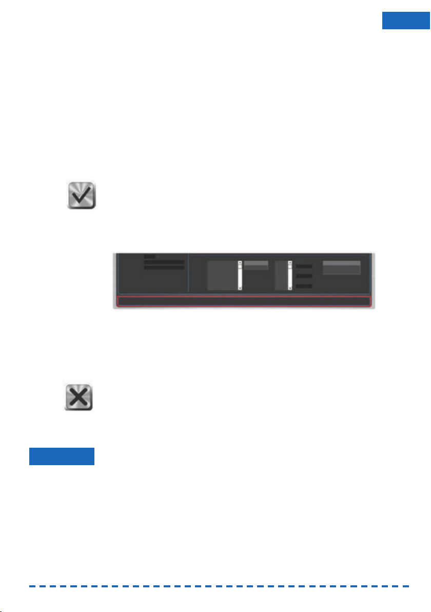
7
ENU
S 1. In the drop-down list with storage devices [A] select the device which contains
the file you want to import.
The application updates the list with folders [B] and displays the folders on the
selected storage device.
S 2. To open a folder, double click on its name in the list [B].
In the list with files [C] the application displays the files in the selected folder
that you can import.
If there are no importable files in the folder, the file list remains empty. Which
files you can import depends on the context in which you opened the window for
file selection. For further information see the corresponding passages in these
instructions for use.
S 3. Mark the file you want to import in the file list [C].
S 4. Click on the depicted icon.
a) The window for file selection closes.
b) The program imports the selected file.
The info area
The info area is located at the bottom of the FINOCAM and FINOCNC window.
In this area the applications show help texts and general messages.
Illustration 2: The info area at the bottom of the Windows (marked in red)
Cancelling processes
To keep the texts in these instructions for use as short as possible, we only describe
how to complete processes successfully. However, in many places you can also
cancel the process.
S To cancel a process, click on the depicted icon.
The application cancels the current process and closes the corresponding
window.
3 Installation & update
You install and update FINOCAM and FINOCNC together via one setup program.
Incorrect job execution and damaging of the CNC machine if the program
version is outdated and/or incompatible
If you use FINOCAM and/or FINOCNC versions that are outdated or incompatible to
your CNC machine, jobs may be executed incorrectly or the machine may be damaged due to an incorrect machine control.
Only install the newest FINOCAM and FINOCNC version that is released for your
CNC machine.
Always update FINOCAM and FINOCNC to the newest version that is released for
your CNC machine.
NOTICE
Page 46

8
3.1 Checking the system requirements
Make sure that your system meets the following requirements:
• Operating system: 64 bit version of Windows 7 or Windows Vista or Windows 8
• Free hard drive space: ca. 500 Megabyte • Working memory: 2 Gigabyte
• Vertical screen resolution: 800 pixel
3.2 Preparing the Installation/udapte
S 1. Deactivate all energy saver settings of your computer and, if using a mobile
computer, establish a permanent connection to the power source. Keep this
configuration also during operation because otherwise the job calculation can be
interrupted.
S 2. Plug the provided dongle into a free USB port of your computer. Only with a
dongle can FINOCAM and FINOCNC be run and installed.
S 3. Have the newest installation data ready. You receive them from your reseller.
You receive the installation data in a ZIP file. This file contains all necessary data
which you have to copy from the ZIP file before the installation.
S 4. Open the ZIP file and copy the data into a folder.
S 5. Deactivate your anti virus software
during the installation or update
. An activated
anti virus software can prevent the installation or update.
3.3 Starting the installation/upate
For a new install of FINOCAM and FINOCNC on a computer, you always use the setup
program as described in this chapter.
If you want to update FINOCAM and FINOCNC, you have two choices:
• Using the setup program
If you received a new version as a ZIP file. Follow the instructions in this chapter.
• Using the update feature
FINOCNC can automatically update itself and FINOCAM through the internet. We
recommend using this feature. Read the description further below (➲ page 13).
Installation / update via the setup program
FINOCAM and FINOCNC come with multiple components. The following table shows
which components you have to install during a new installation or update and how you
start the installation for each component.
You always have to start the setup program manually ( Kapitel 3.3.1). This is presupposed in the following table.
IMPORTANT
IMPORTANT
Page 47

9
ENU
When updating, you can also install the non-necessary components if technical
circumstances require it.
3.3.1 Installing or updating the core applications
You have prepared the installation ( page 8).
S 1. Start the Setup.exe file in the folder with the installation data.
S2. If windows asks you whether Setup.exe may make changes to your computer,
click on [Yes].
The setup window opens.
Configuring a new installation
S 1. Activate the New radio button.
In the bottom area of the window the setup programs displays a list of
languages.
S 2. Activate the Create Desktop-Icon check field. Otherwise you can only start the
applications through the executable files in the installation folder.
S 3. Activate the Install USB-Driver check field. Without the USB driver the con-
nection to your CNC machine will not work.
S 4. If you want to view STL files on the computer, and there is no application
installed for this, activate the Install STL viewer check field. The viewer is not
necessary for working with FINOCAM and FINOCNC.
Use the STL viewer, for example, to check the strength of walls, the diameter of
drillings etc.
S 5. If you want to change the standard installation folder, enter the desired folder
name in the Destination folder input field.
S 6. In the Language selection list, mark the desired language for the user interface.
You can change this setting in the application settings later on (➲ page 17,
page 52).
S 7. Click on the depicted icon in the bottom right corner of the window.
The installation wizard for the FINOCAM and FINOCNC core applications starts
up.
S 8. In the first and the second window of the installation wizard click on [Next >].
S 9. In the third window of the installation wizard click on [Finish].
Component How to start the
Installation
Necessary when
installing?
Necessary when
updating?
FINOCAM / FINOCNC
core application
Automatically via the
setup program
yes yes
USB driver User choice in the setup
program
yes no
STL viewer User choice in the setup
program
no no
Runtime environment
for C++
Manually via a separate
setup program
yes Only when a new version
of the run time environment is available
Page 48

10
The installation wizard closes. Afterwards, the setup programs of the compo-
nents that you chose to install in the main setup program will start up.
When performing a new installation, you should configure both applications after all
components have been installed. Otherwise FINOCNC, for example, cannot connect to
your CNC machine. You find information on configuring the applications elsewhere:
• FINOCAM: page 17
• FINOCNC: page 51
Configuring an update
S 1. Acticate the Update radio button.
S 2. Only if required, activate the check fields for the desktop icon, the USB driver
and the STL viewer.
S 3. Do not change the text in the Destination folder input field. Otherwise the
setup program will create all FINOCAM and FINOCNC files again instead of
updating the existing ones.
S 4. Click on the depicted icon in the bottom right corner of the window.
The setup program updates FINOCAM and FINOCNC. Afterwards the setup pro-
grams of the components that you chose to (re-)install in the main setup
program will start up.
3.3.2 Installing the STL viewer
You chose to install the STL viewer in the main setup program. The installation
wizard for the STL viewer has started up automatically.
S 1. From the Please select a language drop-down list select the language for the
installation wizard and click on [OK]. You can choose between English and
German. Here we assume that you select English.
The STL viewer can display in English, German, French and Korean. It displays
in the system language by default.
S 2. In the next window click on [Next >].
S 3. If you agree to the licence terms shown in the next window, activate the check
box I accept the terms of the License Agreement. This is required to
continue the installation.
S 4. Click on [Next >].
S 5. If you want to change the standard installation folder, enter the desired folder
name in the Destination Folder input field.
S 6. Click on [Next >].
S 7. If you want to change the start menu folder, enter the desired name in the input
field in the next window.
S 8. Click on [Install >].
The installation wizard installs the STL viewer.
S 9. If you want to view a quick reference guide about the STL viewer’s user interface,
activate the Show Quick Reference Card check box in the next window.
Other wise deactivate it.
A PDF reader is required to view the Quick Reference Card.
S10.Click on [Finish].
You have successfully installed the STL viewer.
IMPORTANT
Page 49

11
ENU
3.3.3 Installing the USB driver
You chose to install the USB driver in the main setup program. The installation
wizard for the USB driver „FTDI CDM drivers“ has started up automatically.
S 1. In the first window of the installation wizard, click on [Extract].
S 2. In the second window of the installation wizard, click on [Next >].
S 3. In the third window of the installation wizard, click on [Finish].
Windows automatically adds the USB driver to your system. The system informs
you about the successful driver installation.
If Windows does not show the success message and does not recognize the USB
driver automatically, you have to install the driver manually. Otherwise FINOCNC cannot connect to your CNC machine. Read the next passage for further information.
Installing the USB driver manually
Your computer is connected to the CNC machine with a USB cable. You can
leave the CNC machine switched off.
S 1. Open the Windows control panel. Under Windows Vista and Windows 7 you find
it in the start menu and under Windows 8 in the settings menu that you access
with <WINDOWS KEY+I>.
S 2. In the control panel open the device manager.
S 3. In the tree structure expand the Other devices node.
Unterhalb des Knotenpunkts Andere Geräte zeigt Windows den Eintrag
USB <–> Serial Cable an. Ein gelbes Symbol mit Ausrufezeichen vor dem
Eintrag weist auf einen unvollständig installierten Treiber hin.
S 4. Click with the right mouse button on USB <-> Serial Cable and select the
context menu item Update Driver Software…
The window Update Driver Software displays.
S 5. Click on Browse my computer for driver software.
The window Update Driver Software now contains an input field that you can
use to enter the storage location of the driver.
S 6. Click on [Browse…].
The window Browse For Folder displays.
S 7. In the installation folder of FINOCAM and FINOCNC open the folder USB and
click on [OK].
The window Browse For Folder closes. The system enters the chosen folder
into the text field in the window Update Driver Software.
S 8. In the window Update Driver Software click on [Next].
S 9. In the window Windows Security click on [Install].
S10.In the next window click on [Close].
You have successfully completed the first USB driver installation.
Install the USB driver for a second time. The differences to the first time are:
• The entry in the device manager below the node Other Devices is now USB
Serial Port.
• In the dialogue Update Driver Software the input field already contains the
correct storage location. You do not click on [Browse…], but instead on
[Next].
• After the last step the device manager contains the entry USB Serial Port
(COM<x>) below the node Ports (COM & LPT). For <x> the system auto -
matically inserts a port number.
FINOCNC is now able to connect to the CNC machine.
IMPORTANT
Page 50

12
3.3.4 Installing the runtime environment for C++
The Runtime environment for C++ is the technical basis for FINOCAM and FINOCNC.
It does not have any function visible to the user.
Incorrect job execution when runtime environment is missing
When the runtime environment for C++ is not fully installed, jobs will not be calculated correctly in FINOCAM. This leads to an incorrect job execution.
Fully install the runtimee nvironment before working with FINOCAM.
★ You have installed the FINOCAM and FINOCNC core applications ( page 9).
S 1. Open the folder with the core applications.
S 2. Open the folder mw.
S 3. In the mw folder open the ZIP file vcredist_x64_vc9.zip and copy the contained
file vcredist_x64_vc9.exe into any empty folder.
Possibly the file name includes a higher number after the vc. In this case the file
is a newer version of the runtime environment. Install it as described.
S 4. Open the folder into which you copied the vcredist_x64_vc9.exe file.
S 5. Open the vcredist_x64_vc9.exe file.
S 6. If Windows asks you, whether vcredist_x64_vc9.exe may make changes to
your computer, click on [Yes].
If the runtime environment or a higher version of it is already installed on your
computer, the installation will be cancelled at this point with a corresponding
error message. In this case the technical prerequisite for FINOCAM and
FINOCNC already exists on your computer. Ignore all further instructions on
installing the runtime environment for C++.
In the other case the installation wizard for the runtime environment displays.
S 7. In the first window of the installation wizard click on [Next >].
S 8. If you agree to the licence terms shown in the next window, activate the check
box I have read and accept the license terms. This is required to continue
the installation.
S 9. Click on [Install >].
The installation wizard installs the runtime environment. If the installation is
successful, the message Microsoft Visual C++ Redistributable has been
succesfully installed will display.
S10.Click on [Finish].
NOTICE
IMPORTANT
Page 51

3.4 Using the update feature
FINOCNC can automatically update itself and FINOCAM through the internet.
To use this feature, connect your computer to the internet.
A firewall can prevent the applications from recognizing and downloading new
versions.
Make sure that both applications have unrestricted access to the internet.
Updating the applications through an icon in the header
When FINOCNC recognizes a new version through an active internet connection,
it displays the depicted icon in the header of the application window.
S To start the update, click on the icon.
The application downloads the new version and installs it.
Searching for a new version in the FINOCNC application settings
In addition to the method described above, you can trigger a manual search for a new
version in the application settings of FINOCNC:
FINOCNC is running ( page 51).
S 1. In the icon bar click on the depicted icon on the left, and then in the lower icon
bar click on the depicted icon on the right.
The machine control view displays.
S 2. In the left column click on the depicted icon.
FINOCNC searches for a new version and indicates this in the info area.
Depending on the technical circumstances this can take between one and mul-
tiple seconds.
If the application does not find a new version, it shows a corresponding message
in the info area.
Otherwise a new window opens with information about the version that was
found.
S 3. If FINOCNC found a new version and you want to install it, click on the depicted
icon.
The application downloads the new version and installs it.
3.5 Viewing the release notes
FINOCNC as well as FINOCAM contain a list of changes made in the individual versions. We recommend viewing these release notes after every update so that you are
always informed about the applied changes.
S To view the release notes, click on the depicted icon in the header of the corres-
ponding application window.
The release notes display. In the left column you see the individual released
versions and next to them on the right the applied changes.
IMPORTANT
13
ENU
Page 52

FINOCAM
14
Page 53

4 Introduction
4.1 The concept of FINOCAM
In order to mill or grind with your CNC machine of the Impression series, you first create jobs in FINOCAM. These jobs contain all necessary information like, for example,
the objects to be machined and their placement in the workpieces (blanks / grinding
blocks). FINOCAM uses the information to calculate all data necessary for job execution. Afterwards, FINOCAM transfers the calculated data to FINOCNC.
FINOCNC controls the CNC machine and executes the jobs. Jobs can be executed
independently from calculations.
For grinding jobs you need a suitable CNC machine. You may also need the optional
wet grinding option. When we describe grinding jobs in these intructions for use, we
assume that you use the required equipment. If you do not process grinding jobs,
ignore the corresponding information.
4.2 Intended use
Only use FINOCAM to calculate jobs for CNC machines that you can select in the
application settings or that the application can read from a dongle ( page 17).
Only use the application on a fully PC compatible device under a supported
operating system ( page 8).
Always use the newest version of FINOCAM that is released for your CNC
machine and operating system. You receive the newest version from customer
support or via the update function of FINOCNC.
All other uses are not intended. FINO GmbH cannot be held reliable for damage
resulting from misuse.
IMPORTANT
15
ENU
Page 54

16
5 The user interface
FINOCAM has a window for the application settings and a window for job processing.
The whole job processing is done in this one window. Only for some functions does
an own window open.
In order to use the many functions of the application, you open different views
through an icon bar in the header of the application window. Every view contains
control elements for one specific area of job processing.
You also call up the window for the application settings through the icon bar.
This window has its own icon bar ( page 23).
The icon bar in the window for job processing:
Illustration 3: The icon bar in the window for job processing
The icons open the following sections (from left to right):
• View for the workpiece archive
• View for importing STL files
• Nesting view
• View for placing bars and drops
• View for editing empty areas
• Window for calculating jobs
• Window for the application settings
The last icon has no function meant for the user.
To open a view or a window, click on the corresponding icon.
The application colours the chosen icon blue. Compare the icon for the nesting
view above ( Illustration 3).
Page 55

17
ENU
6 Starting and setting up FINOCAM
After installation it is recommended to adjust the application settings according to
your working environment and conditions. You usually configure the settings only
once. If necessary, however, you can change the settings at any time.
It requires a restart for the application to apply any of our changes.
You start and configure FINOCAM as follows:
You have installed the application completely.
S 1. Start FINOCAM as follows:
• Through the desktop icon (if installed)
• Through the file FINOCAM.exe in the installation folder.
The program window for job processing displays.
S 2. Click on the depicted icon in the icon bar.
The Settings window opens.
6.1 Adjusting the general settings
You have called up the Settings window.
S Click on the depicted icon in the icon bar.
The view for the general settings displays.
Specifying the interface language
S From the Language drop-down list select the language for the user interface.
Manually specifying the machine type
Incorrect job execution if the wrong machine type is chosen
If you specify the wrong type for the CNC machine which is executing the jobs, the
application will calculate the job data incorrectly. This leads to an incorrect job
execution.
If possible, have the machinetype read from the dongle.
If choosing the machine type manually, make sure to select the right type.
If you calculate jobs for multiple CNC machines with one computer, specify the
corresponding machine type for the next job before the actual calculation.
S 1. Deactivate the Read machine type from dongle check field.
S 2. From the machine type drop-down list select the type of CNC machine for
which you want FINOCAM to calculate the job data.
Configuring technical settings
In the middle area of the current window you mainly find technical settings.
S To activate or deactivate one of these settings, click on the corresponding check
field.
IMPORTANT
NOTICE
IMPORTANT
Page 56

18
You find descriptions of these settings in the following table:
Activating or deactivating the display of the import options
When you import STL data, FINOCAM can perform the following operations:
• Height optimization
• Search for divergent insertion vectors
• Search for drillings
The search for divergent insertion vectors and for drillings are only performed
when using a CNC machine with 5 axes.
These operations can either always be performed or you can specify for every individual object, which operations you want to be performed. The latter option allows you
to save computer processing time (➲ page 36).
S If you want to decide on a per object basis which operations are performed, turn
on the “import options” by activating the Show
import options check field.
Beside the import options, FINOCAM also shows value bars for the 5-axis
release for outer surfaces if you use a 5-axis machine.
S If you want the mentioned actions to always be performed, deactivate the Show
import options check field.
Check field Setting activated Setting deactivated Presetting /
Recommendation
Do not save data
for error handling
FINOCAM only writes
data necessary for
job execution.
When calculating job
data, FINOCAM writes
additional data which can
help service technicians
with troubleshooting
Deactivated
Only activate this setting
on request from customer
service, because it may
cause a huge amount of
data being created on
your hard drive.
Automatically quit
after installation
After FINOCAM has completed the job calculation,
it shuts down.
After the job calculation
the user interface is
shown again. The calculation itself is always done
in the background.
Deactivated
Activate this setting if
you do not need the
application directly
after job calculation.
Read machine type
from dongle
FINOCAM reads the
machine type from the
dongle. After the next
application start you see
the retrieved value in the
current window beside
the Machine type
drop-down list.
FINOCAM uses the
machine type which
you select in the current
window in the Machine
type drop-down list.
Activated
Activate this setting
for safety reasons.
If choosing the wrong
machine type, the
jobs will be calculated
incorrectly.
Different scaling in
X, Y, Z
When creating a workpiece, you can specify
individual values for
the X, Y and Z axis.
The scaling factor is
always identical for all
axes.
Deactivated
Only activate this
setting if you work
with materials which
need different scaling
factors.
Page 57

19
ENU
Specifying the default processing status of calculated objects
Through the 3 option fields in the Status of calculated objects area you specify the
default status which is assigned to already calculated objects.
S Activate the option field next to the desired status:
• Do not process
The application assigns the processing status “do not process” to already
calculated objects. The objects will not be machined again if the job is executed
in the CNC machine once more. They function as “place holders”.
• Process
The application assigns the processing status “process” to already calculated
objects. The objects will be machined again if the job is executed in the CNC
machine once more.
• Already processed
The application assigns the processing status “already processed” to already
calculated objects. The corresponding areas are shown as non-usable empty
areas.
You find further information about the processing status of objects in the chapter on
placing objects (➲ page 37).
Activating or deactivating workpieces and materials for wet grinding
S If you use the optional wet grinding module, activate the Wet grinding module
available check field. Only then will the corresponding workpieces and materi-
als be available.
Saving the settings
S Save your changes by clicking on the depicted icon in the bottom right corner of
the window.
6.2 Specifying the processing settings
In the processing settings you specify for each material individual settings regarding
the following topics:
• Bars
• Drops
• Oversize of fits
• Used tools
• Processing order
You specify the processing settings the following way:
You have called up the Settings window (➲ page 17).
S Click on the depicted icon in the icon bar.
The view for the processing settings displays.
S 2. From the Material selection list on the left side of the window, select the
material whose settings you want to adjust.
S 3. On the right side, specify the setting for the selected material as desired.
Page 58

Specifying the settings for bars
S 1. Adjust the calculation of bars in the Bars area through the following 3 value bars:
• Diameter of node
Specify the diameter of node. The node is the starting point of the bar and
always lies on the border of an object.
• Opening angle
The opening angel specifies with how many degree the bar opens from the
node towards the material border.
Illustration 4: Left: Nodes, Right: Opening angles
• Reducing remaining areas
Specify by how many percent the bars will be reduced if the finishing type
Reduce bars is selected.
S 2. In the Oversize of fits area use the Cavity and Drillings value bars to specify
the oversize of fits in millimetres for the cavity and drillings.
Specifying used tools
S 1. In the Optional tools area if for the selected material tools should be used that
deviate from the standard:
• Roughing with 1.5 mm flat ground cutter
This check field is only displayed for the materials PMMA (burn), wax and
model plaster.
Per standard your CNC machine uses a radius cutter (2 mm) for roughing. To
save milling time, you can use a flat grinded cutter 1.5 mm) for the mentioned
material instead.
• Finish drillings with 1.2 mm flat ground cutter
Per standard your CNC machine uses a radius cutter (1 mm) for drillings. If
you want to use a flat grinded cutter (1.2 mm) in addition to finish drillings,
activate this check field. This allows you to precisely carve out 90° angles.
S 2. To finish drillings, cavities and fissures with a radius cutter (0.6 mm), activate the
following check fields:
• Finish drillings with 0.6 mm radius cutter
• Finish cavities with 0.6 mm radius cutter
• Use 0.6 mm radius cutter for fissures
IMPORTANT
20
Page 59

Specifying diameter of drops
You can have drops conically taper. This prevents the tool from damaging the drop
during job processing.
S In the Diameter of drops area at the bottom of the window specify the diameter
of drops directly at the object (value bar D0) and at the remaining material
(value bar D1).
D0 may not be less than D1 If your input violates this rule, FINOCAM equalizes the
values of D0 and D1.
Specifying the sequence optimization
S Specify through the Sequence optimization drop-down list if you want the
tools or the objects to determine the work order during job execution. For this
select between the entries Parallel processing and Individual processing:
• Parallel processing
The tools determine the work order during job processing. First, the CNC
machine processes
all
objects with
one
tool and then changes to the next
tool until all objects are fully processed with all required tools.
The following diagram illustrates this work order using an example of 2 objects
and 2 tools:
Illustration 5: Parallel processing
Advantage of this work order: The processing time of the job is reduced because
the tools do not have to be changed too often.
Disadvantage of this work order: No object will be finished before the whole job
is completed.
• Individual processing
The objects determine the work order during job processing. The CNC machine
processes
every
object
completely
with all tools before starting with the next
object.
The following diagram illustrates this work order using an example of 2 objects
and 2 tools:
IMPORTANT
21
ENU
Page 60

22
Illustration 6: Individual processing
Advantage of this work order: You can stop the CNC machine during job execution to check the processing quality by visually inspecting the already fully completed
objects.
Do not remove the workpieces from the CNC machine during visual inspection. Even
a slight deviation of positioning when inserting the workpieces again will result in the
machine not finishing the job correctly.
Disadvantage of this work order: Longer processing time because the machine
has to change tools frequently.
Specifying the machining sequence
S Specify the processing order of the objects within one workpiece through the
Machining sequence drop-down list:
• DirectMill optimized
FINOCAM determines the optimal calculation and processing order for the
object in each individual workpiece.
• From left to right
The CNC machine starts with the most left hand object and ends with the most
right hand object.
• From smallest to largest object
The CNC machine starts with the smallest object and ends with the largest.
• According to the list
The CNC machine processes the objects according to the import list from top to
bottom. You create the import list in the view for importing STL files (➲ page 26).
6.3 Specifying the data transfer settings
You have called up the Settings window ( page 17).
S 1. Click on the depicted icon in the icon bar.
The view for the data transfer settings display.
S 2. In the Archive folder text field enter the folder, where you want the data for the
individual jobs to be stored.
S 3. In the Folder for storing processing data enter the folder, where you want
the calculated job data to be stored. FINOCNC reads the data for job execution
from this folder.
IMPORTANT
Page 61

23
ENU
7 Creating workpieces and selecting them for editing
In this chapter we guide you step by step through a typical workflow of creating a new
or administrating an existing job. Follow this guide especially during your first milling
and grinding jobs. The workflow described here comprises the following points among
others:
• Creating or loading a workpiece
• Choosing the material for new workpieces
• Importing STL data for the individual objects
• Placing objects in the workpieces
• Adding bars
• Calculating the job data
Using the workpiece archive
At the beginning of job processing you either create a new workpiece or select a
stored one from the archive.
You have started FINOCAM.
S 1. If the Settings window is open, close it. Restart FINOCAM to apply your
changes.
S 2. Click on the depicted icon in the icon bar.
The workpiece archive view displays. There you also create new workpieces.
If you want to edit an existing workpiece, continue with the designated chapter
( page 25).
7.1 Creating a new workpiece
You create workpieces in the New workpiece area.
S 1. From the Material drop-down list select the material you want to process.
If you select a grinding material, your choice applies to all grinding blocks that
you insert into the block holder for the corresponding job. Therefore, only use
grinding blocks of the same material for one job.
Illustration 7: Selecting a material for a new workpiece
If you use the optional wet grinding module and want to create a grinding job,
but the corresponding materials are missing in the list, check if you activated the
Wet grinding module available check field in the general application settings
( page 17).
FINOCAM displays default values for the selected material in the Dimensions
and Height drop-down lists.
IMPORTANT
Page 62

24
S 2. For grinding blocks select the size in the Dimension drop-down list. The drop-
down list displays the different sizes as designated by the corresponding manufacturer.
For blanks the drop-down list only contains the default diameter of 98.5 mm.
You cannot change this value.
S 3. For blanks select the height in the Height drop-down list.
For grinding blocks the height is determined by the block type which you select-
ed in the Dimensions drop-down list. Therefore, you cannot change the Height
value for grinding blocks.
S 4. In the Scaling input field enter in how far FINOCAM should compensate for the
shrinking during sintering when placing objects in the workpiece.
Example: 1.25.
S 5. If necessary, enter a lot number into the Lot number input field.
S 6. If necessary, enter a comment for the job into the Comment input field.
Use comments for your notes about the job.
S 7. Click on the depicted icon below the Comment input field.
FINOCAM assigns a unique ID number to the workpiece and adds a workpiece
card into the workpiece archive. This card appears at the first position below
the text Workpiece archive. The card contains a thumbnail of the workpiece as
well as several job details.
The colour of the workpiece helps you to recognize the material. For example,
zirconium oxide is displayed as white and PMMA as yellow.
Illustration 8: Workpiece cards in the archive:
On the left with a Blank, on the right with a grinding block.
The data on the workpiece cards from top to bottom:
• ID number
• Material
• Dimensions
• Height
• Lot number (if entered, otherwise you see a blank line)
• Scaling factor
Because the new workpiece is now in the archive, you can now select it for processing.
Page 63

25
ENU
7.2 Selecting a workpiece from the archive
To process workpieces, you first select them in the workpiece archive. If you select a
previously used workpiece, you can place additional objects onto the unprocessed
areas, allowing you to use the workpiece further.
Illustration 9: Workpiece cards in the archive
In this view you can also start the calculation of workpieces. As the job calcula-
tion is the last step of job processing, you find the description of this function
later in these instructions for use ( page 45).
You have called up the workpiece archive which contains at least one workpiece
card.
S 1. If the desired workpiece card is not shown on the first page of the archive, use
the scroll bar at the right border of the window to search through the whole
archive. If your archive is very large, we recommend using the filter (see below).
S 2. To edit a workpiece, click on the depicted icon in the corresponding workpiece
card.
If you selected a workpiece with
no
existing objects, the application switches
to the STL file import. There you can import STL files containing objects
( page 26).
If you selected a workpiece
with
existing objects, the application switches directly to
the nesting view. In this view you can move the existing objects ( page 26).
Using the filter in the workpiece archive
In order to only show workpieces that meet certain criteria, use the filter in the Filter
area. As soon as you change a filter criterion, FINOCAM adjusts the displayed workpiece cards immediately.
Note that all criteria are optional.
S 1. In the Material selection list mark the desired material. Selecting the entry All
removes the filter.
Page 64

26
S 2. In the Dimensions selection list mark the desired dimension of the workpiece.
Selecting the entry All removes the filter.
S 3. In the Height selection list mark the desired height of the workpiece. Selecting
the entry All removes the filter.
S 4. Enter the ID number of the desired workpiece into the ID input field.
As every ID can only occur once, you only filter out
one
single workpiece with
this criterion. However, FINOCAM continues to apply the other filter criteria as
well so that the desired workpiece may not display. Therefore, we recommend
removing the other filter criteria so that they do not prevent the desired workpiece from being shown.
S 5. Enter a lot number into the Lot number input field.
S 6. Enter a combination of characters into the Comment input field which has to
occur in the comment field of the desired workpiece. This function also finds
combinations of characters within words. It is not case sensitive.
This function does not search comments for keywords but only for exact combinations of characters. For example, if you enter “Bridge zirconium oxide”, this
text has to occur in the comment field of a workpiece
exactly like this
for the
workpiece to display in the archive. It is not sufficient if only “Bridge” or
“Zirconium oxide” or “Zirconium oxide Bridge” occurs in the comment field.
7.3 Deleting a workpiece from the archive
You have called up the archive.
S 1. To delete a workpiece and with it the job, click on the depicted icon in the
corresponding workpiece card.
S 2. Confirm the safety prompt in the window that opens.
FINOCAM immediately deletes the workpiece from the archive.
8 Importing STL files
In order to place objects in a workpiece, you first have to import the corresponding
STL files into FINOCAM.
The import of STL files is done in the following steps:
IMPORTANT
IMPORTANT
Page 65
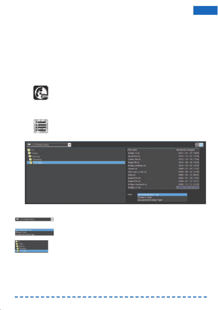
27
ENU
FINOCAM offers two options to select STL files:
• Via a file browser which you use to navigate to the desired files. When selecting
files this way, you are very flexible, however, file selection takes a bit of time.
• Via a root directory into which you copy all STL files. FINOCAM only offers you
the files in the root directory, which allows to select files quickly. However, you
are limited to the files in the root directory.
Which option you choose is only a matter of your preference and does not affect the
job editing in FINOCAM. You can switch between the two options at any time.
Calling up the view for importing STL files
If you selected an empty workpiece in the archive, the view for importing STL files will
display directly and you can skip the following step.
You have selected a workpiece for editing.
S Click on the depicted icon in the icon bar.
The view for importing STL files displays.
8.1 Selecting an STL file via the file browser
★ The view for importing STL files is open.
S 1. In the top right corner of the window click on depicted icon.
In the top area of the window the file browser displays: On the left you see the
folder structure of the selected storage device (per standard your computer’s
hard drive) and on the right the files which are contained in the marked folder.
Illustration 10: The file browser in the view for importing STL files
S 2. If you want to change the storage device, select the device which contains your
STL files from the depicted drop-down list in the upper left corner.
S 3. In the depicted Filter selection list mark the file format that your files use. The
application does not show files in other formats.
S 4. In the depicted folder list doubleclick on the folder with the desired STL files.
S 5. In the file list mark the desired file. The file list looks like the root directory
( Illustration 12).
In the bottom left corner of the window FINOCAM shows the selected object from
the top (left) and from the side (right).
If the application does not show one or both images, the corresponding preview
has been disabled.
Page 66

28
8.2 Importing STL files via a root directory
If you want to import STL files via a root directory, you first have to specify the directory. You can change it at any time.
If you change the root directory regularly, selecting files via the file browser may be
the faster option ( page 27).
8.2.1 Specifying the root directory
S 1. In the top right corner click on the depicted icon.
The window for selecting the root directory opens.
Illustration 11: Window for selecting the root directory
S 2. Navigate to the desired folder and mark it.
S 3. Click on the depicted icon.
The window closes. FINOCAM saves your input.
8.2.2 Selecting STL files
You have specified the desired root directory.
S 1. In the top right corner click on the depicted icon.
In the top right area a list of files in the current root directory displays.
Illustration 12: STL file list (root directory and file browser)
HINT
Page 67

If none of the existing files in the directory are shown, the filter possibly prevents
the files from showing. For more information read the next instruction.
S 2. In the depicted Filter selection list mark the format of your files. The application
does not show files in other formats.
S 3. In the file list mark the desired file.
In the bottom left corner of the window FINOCAM shows the selected object from
top view (left) and from side view (right).
If the application does not show one or both of the images, the corresponding
preview has been disabled.
8.3 Activating or deactivating the STL file preview
In the view for importing STL files FINOCAM shows a preview for the marked file from
top view and from side view. You can activate or deactivate both previews independently from each other.
Illustration 13: STL file preview: Top View (left) and side view (right)
Toggling the visibility of the top view
S Click on the depicted icon.
The application adjusts the interface immediately. The icon changes colour:
blue » the preview is activated, black » the preview is deactivated.
Toggling the visibilty of the side view
If you deactivate the side view for an object that you moved vertically within the workpiece, you will lose this adjustment!
S Click on the depicted icon.
The application adjusts the interface immediately. The icon changes colour:
blue » the preview is activated, black » the preview is deactivated.
8.4 Moving objects vertically within the workpiece
By default, objects are placed in the middle of the workpiece. You can, however,
move objects to a specific vertical position in the workpiece.
In the view for importing STL files you have selected a file whose side view is
shown as a preview. If necessary, activate the side view.
If you have activated the side view and yet no corresponding preview of the
object is shown, deactivate and activate the side view until the preview is shown.
S 1. Move the scroll bar on the right of the side preview to the top or the bottom.
The horizontal line indicates the middle of the workpiece.
The preview image moves into the corresponding direction.
IMPORTANT
29
ENU
Page 68

30
Illustration 14: Object that was moved down
S 2. As soon as the object is at the desired position, check if FINOCAM has marked
areas at the top or bottom margin of the object in red. These areas are positioned outside the workpiece and cannot be processed by the CNC machine.
The red areas can be very small. Check carefully!
You have specified the vertical position of the object in the workpiece.
8.5 Placing sinter bars or sinter plates
You have selected a file in the view for importing STL files.
S 1. Click on the depicted icon.
The window for placing sinter bars opens.
Window for placing sinter bars/plates with sinter bar
S 2. To place a sinter bar, click on the depicted icon on the left.
To place a sinter plate, click on the depicted icon in the middle.
To place a sinter bar with connected end points, click on the depicted icon on
the right.
FINOCAM draws the sinter bar or plate into the illustration of the object
( Illustration 15).
S 3. If necessary, adjust the sinter bar or sinter plate with your mouse. For this, press
and hold the left mouse button:
• You “draw” sinter bars along the object.
• When adjusting sinter plates, you drag the end points until the surface meets
your requirements.
• You “draw” sinter bars with connected end points along the object. When you
are finished, FINOCAM connects the end points automatically.
IMPORTANT
Page 69

S 4. Set the height of the bar or plate in millimetres via the Height slider.
S 5. Set the width of sinter bar ins millimetres via the Width slider.
The volume of the sinter bar or sinter plate should equal the volume of the object.
S 6. Click on the depicted icon.
The window for placing sinter bars and sinter plates closes. FINOCAM stores
your input.
8.6 Selecting the type of an object
You specify the type of an object so that the application can calculate it correctly.
You have selected a file in the view for importing STL files.
S In the Object type selection list mark the appropriate type.
If the 5 axis release outer surface value bars display, they are set to the
default value for the selected object type.
The value bars only display if the Show import option check field is activated
in the general application settings and if you are editing a job for a machine with
5 axes. ( page 17).
The object type will be indicated by an icon in the import list after the import.
Which icon stands for which entry in the Object type selection list can be found
in the description of the import list. ( page 33).
8.7 Specifying the processing quality (precision)
FINOCAM can calculate objects with different levels of precision. The lower the precision/quality, the faster the calculation and the execution in the CNC machine.
The selected level of quality affects the distance between the milling paths on the
outer surfaces. Fits, however, are always calculated with the same accuracy.
You activate or deactivate this function as follows:
You have selected a file in the view for importing STL files.
S Click on the depicted icon(s) as often as until the icon displays the desired
number of stars. They indicate 3 different levels of quality:
• 1 star = fast
• 2 stars = standard
• 3 stars = optimal
8.8 Specifying the 5-axis release of an object
The value bars only display if the Show import option check field is activated
in the general application settings and if you are editing a job for a machine with
5 axes. ( page 17).
With the two value bars in the 5 axis release outer surface area you specify to what
degree the rotary axes of the CNC machine will be slanted in order to machine the
undercuts on the outer surfaces. The maximum angle is 15°.
The Occlusal value bar affects the top angle when machining object.
The Cavity value bar affects the bottom angle when machining objects.
IMPORTANT
31
ENU
Page 70

Illustration 16: Left: occlusal; Right: cavity
You use the function as follows:
You have selected a file in the view for importing STL files.
S 1. Specify the desired angle through the Occlusal value bar.
S 2. Specify the desired angle through the Cavity value bar.
8.9 Specifying the import options
Through the import functions you specify how FINOCAM processes the data files for
job execution.
FINOCAM only shows the import options if the Show import options check field is
activated in the general application settings ( page 23). In addition, some of the
import options also require a 5-axis machine.
S To activate or deactivate an import option, click on the corresponding icon.
The icon changes and indicates the new status.
You normally deactivate import options to save computer processing time during the
import. We recommend activating the import options for all objects.
FINOCAM offers the following import options (left icon – the corresponding option is
activated, right icon – the corresponding option is deactivated):
Height optimization
By default, objects are vertically centered within the workpiece with a setting angle
of 0°.
If you activate the height optimization, FINOCAM automatically checks whether the
object is too high for the selected workpiece. If this is the case, the application tries
to place the object in the workpiece nevertheless by altering the setting angle.
Search for divergent insertion vectors (only for 5-axis machines)
If activated, FINOCAM automatically checks whether the insertion vectors of the
object are parallel to each other or if they are divergent. If they are divergent, the job
will be executed with 5 axes.
Search for drillings in objects (only for 5-axis machines)
If activated, FINOCAM automatically checks whether the current object has drillings
and uses the result during job calculation.
IMPORTANT
32
Page 71

8.10 The import list
The import list contains all imported objects before they are added to the job.
8.10.1 Adding an object to the import list
You have selected a file in the view for importing STL files and specified the
import options.
S 1. Click on the depicted icon.
FINOCAM adds the current object to the import list.
S 2. Check whether the application shows a green icon next to the height value of the
new entry. In this case the height of the work piece is sufficient for processing
the object. If the icon is red, the object is too high for the workpiece.
S 3. In case of a red icon, move the object vertically ( page 29). If this is not suc-
cessful, you have to create a different job for the object with a higher workpiece.
Illustration 17: Import list with two entries. The green icon indicates a sufficient height.
8.10.2 Removing an object from the import list
If you remove an object from the import list, no security prompt is shown. The object
is deleted immediately.
S Click on the depicted trash can icon in the top right corner of the desired entry.
FINOCAM removes the corresponding object immediately from the import list.
8.10.3 Changing the import options of an object after adding it
Via the import list you can adjust the import options for any object after it has been
added to the list. FINOCAM indicates the selected import options for each object with
the following icons:
IMPORTANT
Icon Meaning
Processing quality: fast
Processing quality: standard
Processing quality: optimal
Height optimization activated
33
ENU
Page 72

*This option only displays if the Show import option check field is activated in
the general application settings and if you are editing a job for a machine with
5 axes ( page 17).
In addition, the application also indicates the type of work through an icon:
Icon Meaning
Height optimization deactivated
Search for divergent insertion vectors activated*
Search for divergent insertion vectors deactivated*
Search for drillings activated*
Suche nach Bohrungen deaktiviert*
Extend of 5-axis release*
Top value bar: Occlusal
Bottom value bar: Cavity
Icon Meaning
Crown/bridge
Crown/fully anatomical bridge
Inlay
Abutment
Telescope crown
Model plate
Model cast
Bite spline
Model plug-in tooth
34
Page 73

Changing import options
S Click on the corresponding icon in the import list.
FINOCAM adjusts the corresponding import options and the icon indicates the
new status.
For an explanation of the import options read the corresponding chapters in these
instructions for use ( page 32-33).
8.10.4 Adding the import list to the job
In order to place objects in the workpiece, you add them to the job.
As soon as you have added objects to the job, you can no longer change their import
options. If you want to change the import options of an already imported object nonetheless, you have to remove it from the job and re-import it with the desired options.
The import list contains the desired objects.
S 1. Click on the depicted icon.
If at least one object is too high for the workpiece, you receive a corresponding
message.
S 2. If objects are too high: To add them to the job nonetheless, click on the depicted
icon on the left. In order to cancel the import for
all
objects, click on the depicted
icon on the right.
If you actually added objects to the job, FINOCAM immediately switches to the
view for placing objects in the work piece (the “nesting view”).
In order to add additional objects to the job, call up the view for importing STL
data again and repeat the steps described above.
9 The nesting view: Placing objects in the workpiece
To place imported objects in the workpiece of the current job, you use the nesting
view.
You can place an object only once per import. If you want to use an object multiple
times, import the corresponding STL file as often as required.
Calling up the nesting view
If you added objects to the job via the import list, FINOCAM shows the nesting view
automatically and you can skip the following step.
S Click on the depicted icon in the icon bar.
The nesting view displays.
The workpiece display
On the right hand side of the nesting view you find the workpiece display which shows
the workpiece with all imported objects. FINOCAM automatically places new objects
in the middle of the workpiece display. From there you move them to the desired
place. To use most of the surface area of blanks and to correctly position bars in
grinding blocks, you also rotate the objects.
If you are editing a job that was already executed in the machine before, you may see
black areas in the display view. These areas contain already machined objects and
therefore cannot be used again. You can, however, place objects on the remaining
unused areas to further use the partially processed workpiece. In the chapter on editing empty areas is described how to unlock the black areas to place objects on them
again ( page 35).
HINT
IMPORTANT
IMPORTANT
35
ENU
Page 74

Illustration 18: Two workpiece displays: Grinding block with three objects (left) and
blank with two objects (right)
The list of imported objects
You find a list with the imported objects in the middle of the left side panel. The familiar icons that are also used in the import list show the specified import options like
the level of processing quality. However, you cannot apply any changes anymore.
Click on the icons to see a note in the info area about the import options.
If you click on the file name of an entry, the corresponding object in the workpiece
display is marked. For this to work, do not click on the thumbnail of the object at
the left border of the list, because this will change the object’s processing status
( page 38).
Illustration 19: List of imported objects with two entries
9.1 Moving and rotating objects
You have called up the nesting view. The current job contains at least one
imported object.
S 1. To move an object, position your mouse above the corresponding illustration in
the workpiece display, press and hold the left mouse button and “drag” the
object to the desired spot. Then release the mouse button.
If objects overlap too much or exceed the workpiece border, the application
marks the affected areas in red. In addition, you receive a warning message in
the top left corner of the workpiece display. If you do not correct this incorrect
placement, you cannot calculate the job!
HINT
IMPORTANT
36
Page 75

S 2. If necessary, rotate the objects to the left or the right:
• Rotating in steps of 1°:
Press and hold the mouse button and press <ARROW KEYS UP> or
<ARROW KEYS DOWN>.
• Rotating in steps of 5°:
• Press and hold the mouse button and press <ARROW KEYS LEFT> or
<ARROW KEYS RIGHT>.
• Rotating in steps of 90°:
Press and hold the mouse button and press <STRG+ARROW KEYS LEFT> or
<STRG+ARROW KEYS RIGHT>.
9.2 Special requirements when placing objects in grinding blocks
FINOCAM automatically places one bar in every grinding block. It runs from the left
side of the object to the block holder. FINOCAM determines the size of the bar on the
basis of the size of the object.
Insufficient adhesion of bars due to wrong placement
If bars are placed on concave surfaces and/or surfaces with too little material thickness, the adhesion of the bars may be insufficient.
Before placing the objects, check their surface on the basis of the STL data and
rotate them in the nesting view so that bars are only placed on convex surfaces
of sufficient height. Read more information on this elsewhere ( chapter 10.5,
page 42).
You do not see the automatically placed bar in the workpiece display.
Illustration 20: Object in a grinding block with drawn in bar (in black)
Keeping safety distances
When placing objects in grinding blocks, you have to keep safety distances on the left
and on the right side.
On the left margin of the block you may not exceed the two lines. On the right margin
of the block keep a short safety distance.
Illustration 21: Drawn in safety distances
The snap-to placement aid places objects in workpieces in the best possible way.
For more information read the next section.
NOTICE
HINT
37
ENU
Page 76
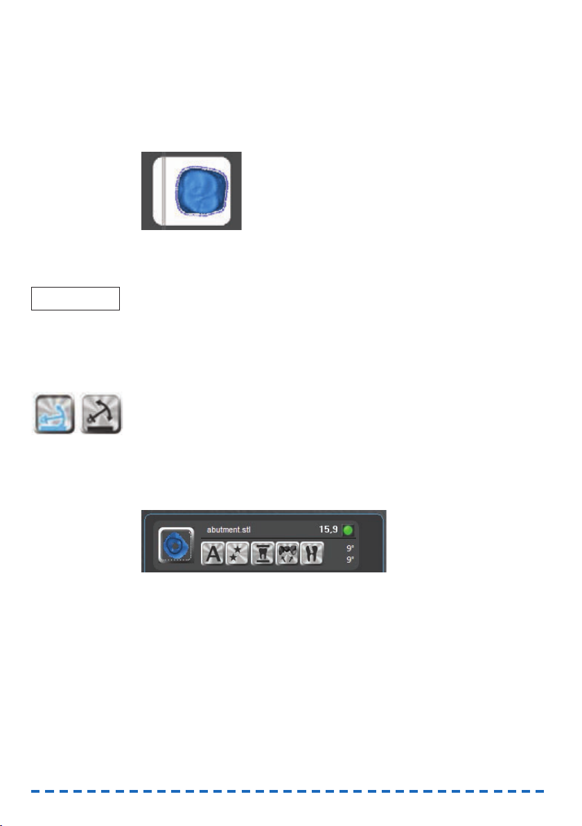
38
Using the snap-to placement aid
With the snap-to placement aid positioning of objects in grinding blocks is fast and
optimized for a correct job execution.
If you activate this aid, the application places the objects into a fixed, optimized position within the grinding blocks as soon as you drag them onto a block. You can then
only move objects
between
but not
within
grinding blocks. The objects are anchored
to the individual blocks.
Illustration 22: Object in a grinding block places with the snap-to placement aid
When the snap-to placement aid is deactivated, you place the objects freely with your
mouse ( page 49).
For high quality grinding results use the placement aid. Especially after rotating
objects, you should “drag” them a short distance
within the grinding block
if the
placement aid is activated. The application then places the objects into an optimized
position.
Activating and deactivating the snap-to placement aid
You are currently editing a grinding block.
S Click on the depicted anchor icon in the top left corner of the workpiece display.
FINOCNC toggles between activated and deactivated placement aid. Blue icon
» activated placement aid, black icon » deactivated placement aid.
9.3 Specifying the processing status of objects
Through the thumbnails in the list with imported objects, you change the processing
status of the individual objects. The colours of the illustrations change depending on
the selected machining state.
Illustration 23: Specifying the processing status
S Click as often on the thumbnail of the corresponding object as until the desired
processing status displays.
You find the available processing statuses and the corresponding colours in the
table below.
FINOCAM colours the thumbnail and the object in the workpiece display in the
colour of the selected processing status.
IMPORTANT
Page 77

9.4 Removing objects from jobs
S To remove an object from a job, assign the processing status “deleted” to it.
FINOCAM removes the object from the workpiece display immediately. In the list
of objects, however, the object will still be listed until you call up the job in the
workpiece archive again.
10 Setting bars and drops
After having placed objects in the workpiece, you set the required bars and drops for
milling jobs. For grinding jobs there is exactly one bar per grinding block which is set
automatically by the application ( page 37 and page 42). Therefore you cannot
call up the view for settings bars and drops when editing grinding jobs.
Insufficient adhesion due to an incorrect placement of bars
If you place bars into the wrong position, their adhesion may be insufficient.
Note the important information on setting bars
( chapter 10.4, page 42)
Calling up the view for settings bats and drops
You are editing a milling job.
S Click on the depicted icon in the icon bar.
The view for setting bars and drops displays.
On the right side you see the workpiece display which shows the workpiece with the
existing objects. You find the icons for setting bars and drops in the middle of the left
side panel.
Workpiece display Thumbnail Assigned processing status
Blue
Process – the object will be machined in the
CNC machine.
Dark blue
Do not process – the object will not be machined
in the CNC machine. You cannot move the object
in the workpiece display.
Green
Already processed – the object has already been
machined in the CNC machine. You cannot move
the object in the workpiece display.
Empty
Black
Deleted – to remove objects from the job, you assign
this state. FINOCNC removes the objects from the
workpiece display, but not yet from the list of objects.
There the thumbnail is displayed in black.
NOTICE
39
ENU
Page 78

40
10.1 Setting bars
You have called up the view for setting bars and drops.
S 1. Select the finishing type for the bar you want to set by clicking on one of the
depicted icons:
• None (left icon) – The bar will not be further machined after finishing
(it displays white in the workpiece display)
• Reduce (middle icon) – The bar will be reduced after finishing
(it displays yellow in the workpiece archive)
• Remove (right icon) – The bar will be removed after finishing
(it displays orange in the workpiece display)
If you do not select a finishing type, the application assigns the preselected
option None.
The selected icon displays in blue.
You can also change the finishing type after setting a bar by pressing <STRG>
( page 44). To save time, we recommend specifying the finishing type
before
setting a bar.
S 2. Click on the depicted icon.
S 3. In the workpiece display click on the spot at the border of the desired object,
where you want to set the bar.
FINOCAM places the bar at the desired spot in the workpiece display.
The active bar always displays in dark blue. As soon it is no longer active, its
colour is determined by the assigned finishing type (see step 1).
Illustration 24: Object with two bars
In addition, the bar receives an entry in the table in the left side panel:
Illustration 25: Table containing two bars
The table contains the following columns:
• No – A continuous number that is assigned to the bar.
FINOCAM allocates this number automatically.
• Z 1 – Height coordinate of the node
• Z 2 – Height coordinate of the endpoint
See the corresponding illustration for an explanation of the terms “node” and
“endpoint” in the current context ( Illustration 26).
HINT
Page 79

41
ENU
10.2 Changing the finishing type of bars
S 1. With the left mouse button click on the desired bar in the workpiece display.
FINOCAM displays the bar in the workpiece display in blue.
S2. Press <STRG> as often as until the desired finishing type is selected. The blue
icon in the side panel indicates which finishing type is currently selected.
10.3 Moving bars vertically
By default, FINOCAM places bars with minimum distance above the equator of an
object. If necessary, you can vertically move the bar. For this you adjust the height of
the node (starting point of the bar) or of the end point of the bar. To do this, use the
side view in the left side panel.
Illustration 26: Side view: Object with bar
A: Node B: End point C: Bar
If you set the node and the end point to a different height, FINOCAM positions the bar
askew in the workpiece.
Specifying the height of the node and the endpoint
If you want the height of the node and of the end point to be different, adjust the
height of the node first. When you do this, FINOCAM positions the bar parallel to the
equator. Therefore, if you moved the endpoint before the node, this change would be
reverted.
S 1. Position the mouse pointer above the node [A] in the side view.
The mouse pointer takes the depicted shape.
S 2. Press and hold the left mouse key and “drag” the point upwards or downwards.
a) FINOCAM positions the bar parallel to the equator of the object.
b) The height of the whole bar adjusts to the height of the node.
c) The line in the table associated with the bar changes: The value in the Z1
table column contains the new height of the node.
S 3. Release the mouse button.
S 4. To position the bar askew in the workpiece, position the mouse pointer over the
endpoint in the side view [B].
The mouse pointer takes the depicted shape.
S 5. Press and hold the left mouse button and “drag” the point upwards or
downwards.
a) FINOCAM moves the endpoint and positions the bar accordingly.
b) The line in the table associated with the bar changes: The value in the Z2
table column contains the new height of the node.
S 6. Release the mouse button.
IMPORTANT
Page 80

42
10.4 Moving bars horizontally
S 1. In the workpiece display click on the desired bar and press and hold the left
mouse button.
S 2. „Drag“ the bar to the desired spot.
S 3. Release the mouse button.
10.5 Important information on setting bars
For a successful job execution you have to place bars correctly. Regard the following
information. You check the objects’ surfaces on the basis of the STL models by using
a suitable application.
FINOCAM comes with an STL viewer which you can use to view STL files directly on
the computer that is running FINOCAM. You find more information about this in the
chapter on installing FINOCAM (➲ page 7).
10.5.1 Placing bars on convex surfaces of sufficient height
When editing milling jobs as well as grinding jobs, you should place bars at convex
surfaces with a sufficient material thickness. This prevents too low adhesion of the
bars. Additionally, subsequent manual works may be required otherwise.
For grinding jobs the position of the single bar is fixed. Therefore you influence the
location where the bar touches the object by rotating the object ( page 36).
In the following illustration of an inlay the material thickness on the left side is too low
to place a stable bar. However, the right side is suitable.
Illustration 27: STL model of an inlay with drawn in bars
To take this into account e.g. when placing an object for a grinding job, you rotate the
object in the workpiece display accordingly. The side where you want the bar to touch
the object must be on the left:
Ilustration 28: The inlay in the workpiece display:
On the left rotated correctly, on the right rotated incorrectly
This cap also has surfaces which are not equally suitable for bars. In the following
illustration the bar is placed at a suitable, slightly convex surface:
IMPORTANT
HINT
Page 81

43
ENU
Illustration 29: STL mode of a cap: Suitable surface for a bar
However, a different, concave surface is less suitable for bars:
Illustration 30: STL model of a cap: Less suitable surface for a bar
Regard the quality of the surfaces for all objects and all jobs!
10.5.2 Additional information for milling jobs
In addition to information given above, regard the information in the following table
when placing bars in blanks. Only then can jobs be executed achieving high quality
results and without damaging the tools.
IMPORTANT
Correct
Incorrect
Description
Place bars evenly on all sides
If you place bars on only one side, vibrations during job
executions may occur. This can lead to the workpiece or
tool getting damaged.
Positive example (left): bars on all sides of the object.
Negative example (right): bars on only one side of the object
Place bars with sufficient distance from each other
If the distance between bars is too low, the air nozzle may not
be able to blow off chips as required, which can damage the
tool.
Positive example (left): bars with a suitable distance between
them. Negative example (right): bars without a suitable distance
between them.
Set enough bars
Per object you should at least place three bars because
otherwise vibrations may occur during job executions.
This can lead to the workpiece or tool getting damaged.
Positive example (left): Enough bars set.
Negative example (right): Too few bars set.
Page 82

44
10.6 Removing bars
S 1. Click on the depicted icon.
S 2. Click on the bar in the workpiece display that you want to remove.
FINOCAM removes the selected bar immediately.
10.7 Settings drops
S 1. Click on the depicted icon.
S 2. Click on the spot in the workpiece display where you want to place the drop.
FINOCAM creates the drop at the choosen position.
10.8 Removing drops
S 1. Click on the depicted icon.
S 2. Click on the drop in the workpiece display that you want to remove.
FINOCAM removes the selected drop immediately.
11 Editing empty spaces
This step is only necessary if the following two conditions apply:
• You are editing a job with previously calculated objects.
• So called “empty areas” are placed where the calculated objects used to be.
When editing a newly created job, for example, you skip this step. In this
case start the job calculation directly after setting bars and drops. Read the
corresponding chapter for more information ( page 45).
What are “empty spaces” in FINOCAM?
Sometimes you have only placed and machined objects in some areas of a workpiece.
FINOCAM shows these areas as empty areas where you cannot place new objects.
After all, the CNC machine cannot machine new objects in these areas if you use the
same physical workpiece.
However, perhaps you want to use a new physical workpiece for a job with already
calculated objects. In this case, the empty areas shown in FINOCAM are in fact
usable on the physical workpiece. Therefore, you unlock the empty areas in the application to place objects in the areas again.
Calling up the view for editing empty areas
S Click on the depicted icon in the icon bar.
The view for editing empty areas displays.
HINT
Page 83

45
ENU
On the right side you find the workpiece display which shows the workpiece with all
existing objects. The application displays empty areas in black.
Illustration 31: Blank with two empty spaces (marked in red)
In the middle area of the left side panel FINOCAM lists alls empty areas. A unique
number and a check box are is assigned to every empty area:
Illustration 32: List of empty areas
11.1 Unlocking empty areas
You have called up the view for editing empty areas. The displayed workpiece
contains empty areas.
S Deactivate the check box for the empty areas that you want to unlock.
FINOCAM hides the corresponding empty areas in the workpiece display imme-
diately and unlocks them. You can now place objects in the areas via the nesting
view and by that use the areas again ( page 35).
11.2 Locking empty areas
You have called up the view for editing empty areas. The displayed workpiece
contains hidden empty areas.
S 1. In the side panel activate the check boxes for the empty areas which you want
to lock.
FINOCAM immediately displays the corresponding empty areas in the workpiece
display. If objects overlap these areas, the application indicates this as usual.
S 2. If necessary, correct overlapping objects in the nesting view because otherwise
you cannot calculate the job ( page 35).
12 Calculating jobs
After having fully prepared a job, you start the calculation of the milling and grinding
data. FINOCAM sends these data to FINOCNC, which controls the job execution in the
CNC machine.
Besides calculating an individual job, you can also calculate multiple jobs in succession via the workpiece archive ( page 47).
Page 84

46
12.1 Calculating individual jobs
You start the calculation of individual jobs as follows:
• Through an icon in the icon bar
• Through an icon in multiple views
The views in which you can start the calculation are:
• The nesting view ( page 35)
• The view for setting bars and drops ( page 39)
• View for editing empty areas ( page 44)
In the mentioned views you find an area in the bottom left corner which contains the
icon for starting the calculation, the estimated job execution time and the estimated
job completion time.
Illustration 33: Area for job calculation
A: Job executation time B: Job completion time C: Icon for starting the calculation
You start the calculation of an individual job as follows:
You are editing a workpiece in which objects are placed.
S 1. In the area mentioned above click on the depicted icon on the left, or in the icon
bar click on the depicted icon on the right.
a) In case the job is without errors the Calculating job window opens. It shows
an overview of the job you want to calculate.
b) In case the job contains errors, e.g. overlapping objects, you will receive an
error message. You find information about error messages that may occur when
starting a job calculation in the corresponding chapter ( page 48).
S 2. If you want the application to create a report on the calculation, and you have
Microsoft Excel installed, activate the Write protocol check field in the
Calculating job window. FINOCAM launches Microsoft Excel with the report
data at the end of the calculation.
Microsoft Excel has to be installed on the computer running FINOCAM. The
application does not create a file that you can open on a different system.
S 3. Start the calculation by clicking on the depicted icon.
FINOCAM hides the user interface and starts the calculation in the background.
FINOCNC launches.
If FINOCNC does not launch, start it manually. FINOCNC controls the job
execution in the CNC machine.
Depending on the application settings, the user interface of FINOCAM displays
again after the calculation has finished, or FINOCAM closes. You specify this in
the general application settings ( page 17).
IMPORTANT
IMPORTANT
Page 85

47
ENU
12.2 Calculating multiple jobs in succession
If you have prepared multiple jobs in FINOCAM, you can calculate them in one
session. For this you use the multi-job calculation function in the workpiece archive:
You have prepared multiple workpieces which are listed in the workpiece
archive.
S 1. To call up the workpiece archive, click on the depicted icon.
The workpiece archive displays.
S 2. If desired, choose which workpiece cards are shown in the archive: In the Multi-
job calculation selection list in the bottom right corner of the workpiece
archive, select one of the following entries:
• All
The application shows all workpieces in the archive.
Note that other filter criteria still apply ( page 26).
• Calculable jobs
The application shows all workpieces with objects that need to be
calculated.
• Selected jobs
The application only shows workpieces that you have selected for
calculation (see step 3).
FINOCAM displays the workpiece cards in the archive according to your
selection.
S 3. Select the jobs you want to calculate by activating the depicted check field on
the corresponding workpiece cards.
S 4. Click on the depicted icon in the bottom right area of the workpiece archive.
The Start calculation window opens, where you can specify the order in which
the workpieces will be calculated.
If you did not select at least one workpiece in step 3, you receive an error
message in the info area and the windows does not open.
Illustration 34: Specifying the order for multi-job calculation
The window shows the workpiece cards of the jobs that you selected for calculation. They will be calculated from top to bottom.
Page 86

48
S 5. To adjust the calculation order, click on one of the depicted arrow icon on the
right border of the desired workpiece card..
After every click on one of the arrow icons, FINOCAM immediately adjusts the
order of the workpiece cards upwards or downwards.
S 6. If you want the application to create a report on the calculation, and you have
Microsoft Excel installed, activate the Write protocol check field in the
Calculating job window. FINOCAM launches Microsoft Excel with the report
data at the end of the calculation.
Microsoft Excel has to be installed on the computer running FINOCAM. The
application does not create a file that you can open on a different system.
S 7. Start the calculation by clicking on the depicted icon.
FINOCAM hides the user interface and starts the calculation in the background.
FINOCNC launches.
If FINOCNC does not launch, start it manuall. FINOCNC controlls the job execu-
tion in the CNC machine.
Depending on the application settings, the user interface of FINOCAM is shown
again after the calculation has finished or FINOCAM closes. You specify this in
the general application settings ( page 17).
12.3 Error messages when calculation job data
The following error messages can occur when starting a job calculation:
IMPORTANT
IMPORTANT
Error message Reason Corrective action
Set bars before calculating the
job.
For at least one object in the
workpiece you have not set bars.
Set bars for all affected objects.
( page 40).
Objects are overlapping. At least two objects in the workpiece
are overlapping too much.
Position all affected objects so that
they do not overlap. ( page 36).
Object exceed the border of
the workpiece.
At least one object has been
positioned so that it exceeds
the workpiece border.
Position all affected objects in the
workpiece within the available area.
( page 36).
Page 87

49
ENU
FINOCNC
Page 88

13 Introduction
13.1 The concept of FINOCNC
FINOCNC is a control program for your CNC machine. Among other things, you use it
for the following tasks:
• Receiving the calculated job data from the CAM software.
• Automatic controlling of the CNC machine for executing jobs.
• Controlling of individual machine functions (e.g. air extraction on/off)
• Milling of calibration and test specimens
• Administrating of the tool changer
• Archiving and restoring job data
The functions of FINOCNC are closely linked to the used CNC machine. Depending
on the machine, different functions will be available. For example, only if you use a
machine with a blank changer will the corresponding options display on the user
interface.
Therefore the illustrations in these instructions for use may not always reflect the
state of your software installation. In this case, missing options are not caused by a
software error.
For grinding jobs you need a suitable CNC machine. You may also need the optional
wet grinding option. When we describe grinding jobs in these instructions for use, we
assume that you use the required equipment. If you do not process grinding jobs,
ignore the corresponding information.
13.2 Intended use
Only use the application on a fully PC compatible device under a supported
operating system ( page 8).
Always use the newest version of FINOCNC that is released for your CNC
machine and operating system. You receive the newest ver- sion from customer
support or via the internal update function of FINOCNC.
Use FINOCNC
only
in the
User mode
. Only participating in a special training at
FINO GmbH entitles the user to run the application in the
Administrator mode
.
All other uses are not intended. FINO GmbH cannot be held reliable for damage
resulting from misuse!
14 The user interface
You control FINOCNC almost completely through one application window. Only for
some functions does an own window open.
Note the general information about the user interface which applies to FINOCAM
as well as FINOCNC ( page 5).
The icon bar in FINOCNC
In order to use the many functions of the application in only one window, you open
different views through an icon bar in the header of the application window. Every
view contains control elements for one specific section.
Through the icon bar you also call up the settings section. This section has an
additional icon bar below the standard icon bar ( page 51).
IMPORTANT
50
Page 89

The following illustration shows the icon bar in the application window of FINOCNC:
Illustration 35: The icon bar in the application window of FINOCNC
The icon open the following sections (from left to right):
• Job execution view
• Tool administration view
• Job log view
• Settings view
To call up a view, click on the corresponding icon.
The application colours the corresponding icon in blue. See the icon for the job
log view above.
15 Starting and configuring FINOCNC
After installation it is recommended to adjust the application settings to your working
surrounding and conditions. For operation it is especially necessary to configure the
connection to your CNC machine. You usually configure these settings only once. If
necessary, however, you can change the settings at any time.
You start and configure FINOCNC as follows:
You have installed the application completely.
S 1. Start FINOCNC as follows:
• Through the desktop icon (if installed)
• Through the FINOCNC.exe file in the installation folder.
The application window opens and the job execution view displays.
S 2. Click on the depicted icon in the icon bar.
You switch to the settings section. This section has an additional icon bar below
the standard icon bar:
Illustration 36: Additional icon bar in the settings section
This additional icon bar opens the following views (from left to right):
•Application settings view
•Tool availability view
•Machine geometry view
•Machine control view
15.1 Specifying the application settings
It requires a restart for the application to take any changes you made into account.
You have called up the settings section.
S Click on the depicted icon in the lower icon bar.
The application settings view displays.
IMPORTANT
51
ENU
Page 90

Specifying the user interface language
S From the Language drop-down list select the user interface language.
Specifying the user profile
Crushing hazard and danger of cuts due to moving machine parts when
using the profiles “Administrator”, “Production” and “Trade fair ”.
If you use a different profile than the standard User profile, you can cause crushing
injuries and cuts to yourself and others. In addition, in these profiles several safeguards of the CNC machine are switched off.
Use FINOCNC with the User profile only unless you have been authorized by
FINO GmbH to use different profiles.
Always switch to the User profile when you do not need any of the other profiles
anymore. In regard to this, read step 3 of the following instructions.
S 1. In the User profile area activate the option field for the desired profile. The pro-
files determine the available functions and operating parameters of FINOCNC:
• User
Standard profile for the daily job execution and the basic machine control.
• Administrator
Advanced machine control for repairing and maintaining through service
technicians.
• Production
Provides options for adjusting the machine during manufacturing.
• Fair trade
Allows for the simulation of job execution without compressed air (“demonstration mode”) and without the corresponding safeguards like the compressed air or vacuum sensor. Usable e. g. at fair trades where no compressed air connection is available. The spindle with the tool moves “through
the air” above the pre-processed workpiece to demonstrate how the CNC
machine operates.
S 2. Except for the User profile, enter the corresponding password. The password
are given to authorized users by FINO GmbH.
S 3. If you want FINOCNC to automatically set the profile to User after the next restart
but one, activate the Reset profile to “user” after second start of the soft-
ware option field.
The function works as follows:
WARNING
!
3rdprogram startup
Function resets
profile to “User”.
2ndprogram startup
The different profile
is activated after
a program restart.
1stprogram startup
A different profile
than „User“ is
selected.
52
Page 91

53
ENU
Activating cleaning reminder
S In order to receive one message per day which reminds you to clean the CNC
machine, activate the Cleaning reminder check field.
Specifying the source of job data
To execute jobs, FINOCNC needs job data previously calculated by a CAM application. You can import these job data in two ways:
• If you use FINOCAM: FINOCNC automatically imports new jobs from a fixed
folder and offers them for execution.
• Via an icon in the job execution view, which you use to manually add job data
created by a different application than FINOCAM.
You can use both import options alongside each other.
S 1. If you want the depicted icon for the manual import of CAM data to display in the
job execution view, activate the Import icon for external CAM data check
field.
S 2. If you use FINOCAM: To specify the folder for the automatic import, click on the
depicted icon and choose the desired folder in the window that opens.
Specifying the duration of job data storage
S Specify through the Number of days of data storage drop-down list for how long
the data of already executed jobs will be stored. As long as jobs are stored, you
can restore them via the log to execute them again ( page 86).
After the specifyied time period FINOCNC deletes the data automatically. The
jobs will still be listed in the job log, however, you will no longer be able to
restore them.
Specifying the USB port number
FINOCNC communicates with the CNC machine through an USB connection. For a
successful connection the right port must be set. You can try to automatically detect
the right port via FINOCNC
S To automatically detect the port, click on the depicted icon.
If the application is able to detect the port number, it enters the number into the
Port number input field.
If FINOCNC does not detect the port number, you have to enter it manually.
You enter the port number as follows:
S 1. Open the control panel:
• Windows 7 and Windows Vista: In the start menu click on Control panel.
• Windows 8: Press <WINDOWS KEY + I> and then click on Control panel
in the Settings side panel.
The control panel opens.
S 2. Double-click on the Device manager entry.
The Device manager window opens.
S 3. In the tree view open the node Ports (COM&LPT)
The node contains an entry USB Serial Port (COM<x>).
<x> stands for the required port number.
S 4. In FINOCNC enter the port number in the Port number input field.
S 5. Close the device manager and the control panel.
Page 92
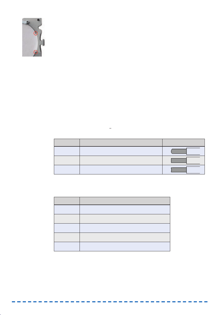
Marking the blank position
If the CNC machine marks blanks at their border with one or two holes, re-inserting
them in the same position is made easier for you.
S To turn on this function, activate the Mark blank position check field.
Activating air extraction when the front cover is opened
When cleaning the working chamber of your CNC machine, it is recommended to
activate the air extraction. Therefore you can specify that the air extraction is automatically turned on when you open the front cover.
S To turn on this function, activate the Activate the air extraction when
opening the front cover check field.
15.2 Configuring tool types
15.2.1 Information about tool types
Structure of tool names in FINOCNC
Form|Diameter|Material
Example: R100 Z
R Abbreviation for radius cutter
100 1,0 mm diameter
Z Suitable for the material “z
irconium oxide”
Tool forms
Materials and associated tool rings
Different tools are suitable for different materials. You recognize the material the tool
is designed for by the final letter in the tool name.
Abbreviation Meaning Form of cutting edge
R Radius cutter or radius grinding tool
F Flat ground cutter
T Torus grinding tool
Abbreviation Meaning
Z Zirconium oxidd
K Plastics
N Composites
NEM NEM (non-precious alloys)
G Glass ceramics
54
Page 93

At the tool itself you recognize by the ring colour for which material the tool is
suitable.
15.2.2 Viewing tool data
In the Tool availability view FINOCNC lists all tools that are available for your CNC
machine by FINO GmbH.
You have called up the settings section.
S In the lower icon bar click in the depicted icon.
The Tool availability CAM software view opens.
The table shows the following information about the tools:
• Name
The tool name (short form) in FINOCNC.
The structure is explained in the previous chapter
( page 54).
• D
The cutting edge diameter in millimetres.
• Cutting edge geometry
Either Face radius or Flat ground depending
on the corresponding cutting edge geometry.
• h
The tool life hours.
• T
A unique identification number for the tool type.
The tool position in the tool changer is also designated with the letter T.
However, there the following number starts with a 0 (e.g. T0
3).
• L sz
The tool shank from top to the ring in millimetres.
The function of the Press down column is described further below ( page 56).
Material Ring colour Example in FINOCNC
Composites Orange/yellow R200 N
NEM Red R200 NEM
PMMA Silver R200 K
Zirconium oxide
Green/light blue/dark blue
R060 Z
IMPORTANT
55
ENU
Page 94

15.2.3 Specifying the tool life
In the Tool availability CAM software view you specify the tool life for each tool
type. The tool life is the maximum number of operating hours that the tools can be
used before it is worn.
FINOCNC stores the remaining operating hours for each tool type separately: The
application subtracts the time in use automatically when the tool is used during job
execution and updates the remaining tool time accordingly. This way you always keep
track of the life of your tools which allows you to replace tools in time.
In addition to the decimal value FINOCNC displays the tool life as a value bar. The
green portion stands for the remaining time, and the red portion stands for the time
that the tool has already been used.
Illustration 37: Value bar for displaying the tool life
On the left: New tool
On the right: Tool after multiple operation hours
To make sure that FINOCNC knows the maximum life of each tool, you specify it as
follows:
The Tool availability CAM software view is being displayed. ( page 55).
S 1. In the h column enter the maximum tool life for the corresponding tool type.
Format: Decimal value in hours (e. g. 12,0 for 12 hours).
S 2. Press <ENTER>.
15.2.4 Activating the press down function for tools
When the spindle of your CNC machine puts a tool into the tool changer, it may not
push the tool into the position completely. For this reason, you can specify for each
tool type that after putting the corresponding tool into the tool changer the spindle
presses the tool into the position again. This makes sure that the tool is pushed in
completely.
This function increases the tool change time only marginally, however, it decreases
the risk of an incompletely pushed in tool significantly. Therefore we recommend
turning on this function for every tool type.
You activate this function for individual tool types as follows:
The Tool availability CAM software view is being displayed ( page 55).
S Activate the check fields in the Press down column for the desired tool types.
15.2.5 Configuring the manual tool change
By default, the CNC machine uses the built-in tool changer to change the tools during
job execution. In some cases such as the following, this may not be desired for
specific tool changer positions:
• A position in the tool changer is worn so that it can no longer properly hold
any tools.
• You use a tool which does not fit into the tool changer.
For these cases you specify in the machine geometry view that the machine performs
a manual tool change for the corresponding positions.
IMPORTANT
56
Page 95

You have called up the settings section.
S 1. Click on the depicted icon in the lower icon bar.
The machine geometry view displays.
In the Positions of tools section on the right hand side, you find a list of all tool
changer positions of your CNC machine.
Illustration 38: List of tool changer positions with entries T01-T16
The first column contains the corresponding position number with a preceding T.
The last column indicates if the manual tool change is activated for the corresponding
position or not.
• Black hand icon: Manual tool change is deactivated
• Blue hand icon: Manual tool change is activated
The columns 2 to 6 contain technical position data which the CNC machine
needs for the automatic tool change. They are mainly used during machine maintenance and therefore are not described here any further.
S 2. For all positions you want to toggle between a manual and an automatic tool
change, click on the corresponding hand icon.
a) FINOCNC changes the colour of the icon.
b) From now on the tool change will be performed according to the new setting.
15.3 Unlocking a wet grinding module for the CNC machine
If you have added the optional wet grinding module to an existing CNC machine,
you need to unlock it
once only
before using it for the first time. You can do this in
FINOCNC in two places:
• Through the icon for the pump control (preferred)
• In the machine geometry view.
If the unlock code is invalid or missing, contact customer support.
Unlocking the wet grinding module through pump control
This is the preferred option because this way you spray liquid into the working
chamber and remove air from the system. This is required before executing the first
grinding job.
57
ENU
Page 96

58
a) You have installed the wet grinding module as described in the operating
manual and filled in the water emulsion. The module’s display is activated.
b) The CNC machine which is supposed to be used with the module is switched
on and connected to the computer.
c) You have called up the settings section in FINOCNC.
S 1. Click on the depicted icon in the icon bar.
The machine geometry view displays.
Illustration 39: Part of the machine geometry view
Check field for unlocking the wet grinding module marked in red
S 2. Click on the depicted icon.
A window opens requesting you to enter the unlock code.
S 3. Enter the unlock code that you received with the wet grinding module.
If the unlock code is valid, the wet grinding module is unlocked for the connected
CNC machine.
Unlocking the wet grinding module in the machine geometry view
In the machine geometry view you can unlock a wet grinding module without spraying
water into the working chamber.
a) You have installed the wet grinding module as described in the operating
manual and filled in the water emulsion. The module’s display is activated.
b) The CNC machine which is supposed to be used with the module is switched
on and connected to the computer.
c) You have called up the settings section in FINOCNC.
S 1. Click on the depicted icon.
The machine geometry view displays.
Page 97

59
ENU
Illustration 40: Part of the machine geometry view
Check field for unlocking the wet grinding module marked in red
S 2. Activate the Wet grinding module unlocked control field.
A window opens requesting you to enter the unlock code.
S 3. Enter the unlock code that you received with the wet grinding module.
If the unlock code is valid, the wet grinding module is unlocked for the connected
CNC machine.
16 Defining your tool stock and tool magazines
You specify your tool stock (all tools you have available) and up to 3 tool magazines
(tools in the tool changer of your CNC) in the tool administration view.
S Click on the depicted icon in the icon bar.
The tool administration view displays.
Illustration 41: The tool administration view with drawn in areas
A: Your tool stock B: Tool magazin selection C: Selected tool magazine
Page 98

60
16.1 Tool cards
In the inventory list [A] as well as in the tool magazine display [C] every tool type is
represented by a corresponding tool card:
Illustration 42: Tool card in the inventory list
D: Serial number H: Icon "Reset remaining tool life"
E: Short tool name I: Remaining tool life as al decimal value
F: Long tool name: J: Value bar for the tool life
diameter&form
G: Icon "Delete tool"*
* In the tool magazine display replaced by the icon for removing the tool from the magazine
(➲ page 61).
16.2 Editing the tool stock
The tool stock list [A] contains all tools type in your stock. It offers positions for
30 entries.
FINOCNC displays tool cards in three different ways: ( Ilustration 43)
• An empty tool card if no tool type is specified for the position.
• Bright display if a tool type is specified for the position which is not assigned
to the currently selected tool magazine [C].
• Dark grey display if a tool type is specified for the position which is assigned
to the currently selected tool magazine [C].
Illustration 43: Different tool card displays
16.2.1 Adding a tool type to the stock
S 1. In an emtpy tool card click on the depicted icon.
The tool types available in the application are offered to you in a list.
S 2. Select the desired tool type from the list.
The selected tool type takes the corresponding position in the stock list.
The added tool type is not yet assigned to a tool magazine. Read in the corre-
sponding chapter how to do this ( page 62).
Page 99

61
ENU
16.2.2 Removing a tool type from the stock
The tool type not assigned to any tool magazine. Otherwise remove it from all
magazines.
S 1. In the desired tool card click on the depicted icon.
S 2. Confirm the security prompt.
FINOCNC replaces the affected tool card with an empty tool card.
16.2.3 Organizing the tool stock with the Administrated Tool Board
For organizing the tools outside the tool changer of the CNC machine, we recommend
the Administrated Tool Board (ATB). It offers 30 slots which correspond to the 30 tool
cards of the stock list in FINOCNC.
If you keep the tools in the ATB and in the stock list identical, all information about
the tool life, geometry etc. remain linked to the corresponding tools, and you have
a much greater selection of tools at your disposal. If you are interested in the ATB,
contact your reseller.
Illustration 44: The Administrated Tool Board With 30 tool positions
Illustration 45: The tools in the ATB correspond to the tool stock list in FINOCNC
Page 100

16.3 Editing tool magazines
A tool magazine in FINOCNC represents a set of tools in the tool changer of your CNC
machine. In the tool administration view you specify up to 3 magazines which you can
quickly select while preparing the job execution.
On the basis of the tool magazines the application knows where to move the spindle
e. g. to change the tools. Therefore you have to specify at least one tool magazine
before job execution.
There are 3 magazines available with the following names:
• Mix
• Zirconium oxide
• Plastics
It is your choice if you select the tools according to the magazine names or if you use
your own classification schema. However, you cannot change the magazine names in
the application.
Selecting tool magazines
In the right area of the view [C] you find the currently selected tool magazine. Its
depiction corresponds to the tool changer in your CNC machine. The individual tool
changer positions are numbered accordingly. If a tool is assigned to a certain position, FINOCNC shows the corresponding tool card. Otherwise you see a grey area.
Illustration 46: On the left: tool card for the assigned tool,
On the right: position without an assigned tool
S To select a tool magazine for editing, select it in the Tool magazine drop-down
list [B].
16.3.1 Adding tools to a magazine
a) You have selected the tool magazine you want to edit.
b) The tool you want to add is in the tool stock list and is not already assigned
to the magazine.
S 1. In the stock list [A] click on the desired tool card and hold the left mouse button.
S 2. “Drag“ the tool card to the tool magazine display [C] and “drop” it onto the
desired empty position.
The tool card occupies the former empty space in the magazine display and the
tool card in the stock list is displayed in grey.
16.3.2 Removing tools from a magazine
You have selected the tool magazine you want to edit.
S In the tool magazine display [C] click on the depicted icon within the desired tool
card.
The application removes the tool card from the magazine display and displays it
in full brightness in the stock list.
HINT
62
 Loading...