

Page 1
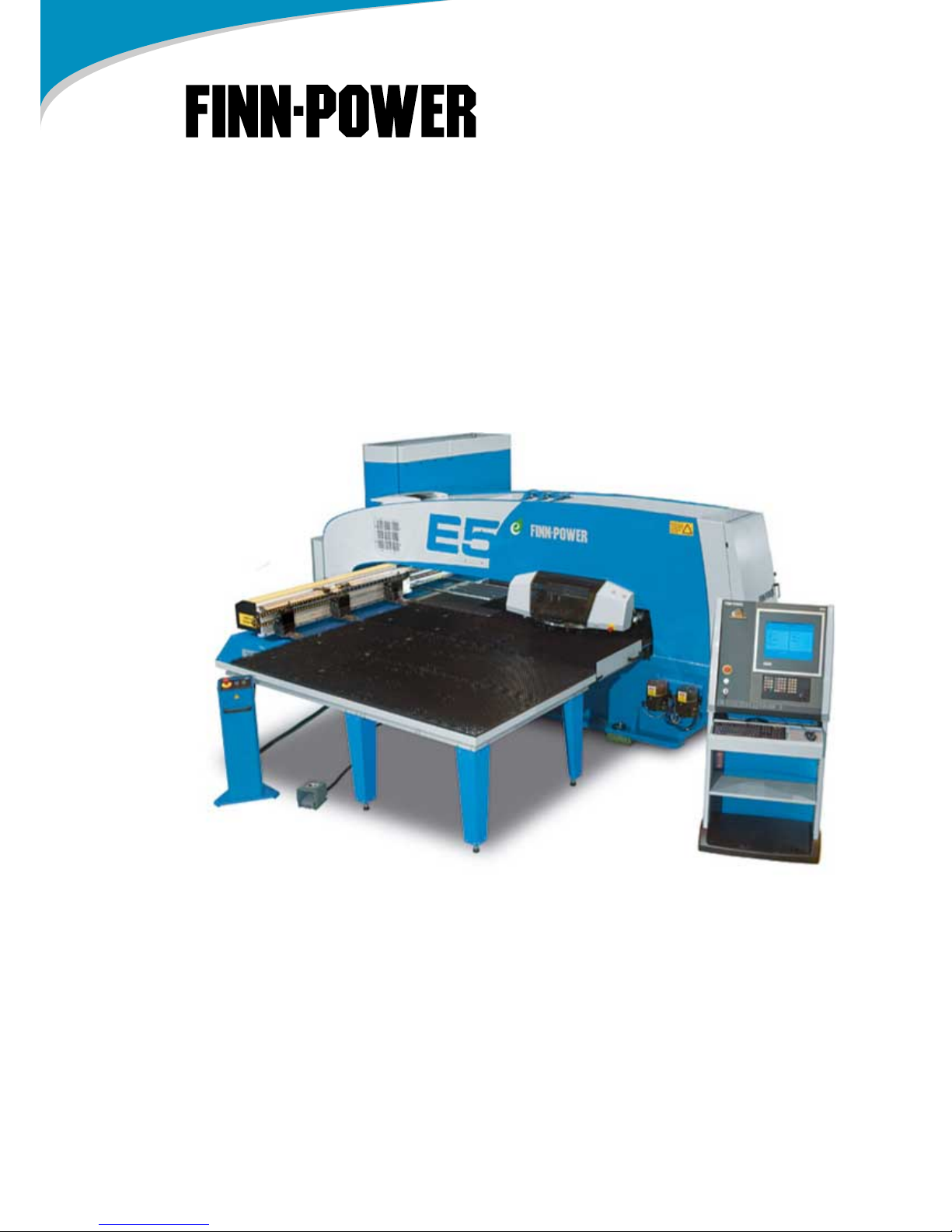
USER GUIDE
E5 TURRET PUNCH PRESS
Series 12.2
Control Siemens 840D
Revision/Date 2/2009-10-22
Page 2

All copyrights, trademarks, patents, and all other intellectual property rights included in this documentation shall
be the exclusive property of the Finn-Power companies or the owners of the material. Except where otherwise
provided by law, the content of this documentation shall not be used, copied, edited, translated, distributed or
otherwise made use of without the express consent of the Finn-Power companies or the owner of the material.
The Finn-Power companies do not guarantee that the content of this documentation is accurate or updated. The
information may be amended, updated or deleted without prior notice.
Further information on the intellectual property rights of the Finn-Power companies is available on written request
from: Customer Documentation, Finn-Power Oy, P.O. Box 38, FI-62201 KAUHAVA, FINLAND.
FINN-POWER, THE FINN-POWER OF LIGHT, FINN-POWER LASER, SHEAR GENIUS, NIGHT TRAIN FMS,
FLEXIBLY YOURS, ENERGY IN EFFICIENT USE, ECOPUNCH, ECOCUT, ECOBEND, ECOMBI, COMBO
FMS, EXNER, TULUS, POWERFORM, NC EXPRESS, SHEAR BRILLIANCE, BENDTERM, BC-EXPERT, FOUR
–IN-ONE, NIGHT TRAIN, EXPRESS, FP, MULTI-TOOL
are registered trademarks of the Finn-Power companies.
Copyright© Finn-Power Oy. All Rights Reserved.
Page 3

Table of Contents
1. Introduction ...................................................................................................... 5
2. Safety instructions ........................................................................................... 6
2.1. Hazard levels .............................................................................................. 6
2.2. Safety symbols ........................................................................................... 6
2.3. Safety during operation and maintenance .................................................. 7
2.3.1. Operation stations and safety zones ................................................... 7
2.4. Safety devices and functions of the base machine ..................................... 8
2.5. Periodic inspection of safety devices .......................................................... 9
2.5.1. Safety light beams ............................................................................... 9
2.5.2. Emergency stop buttons and turret service door ............................... 10
2.5.3. Hydraulic and pneumatic system ....................................................... 11
2.5.4. Service door ...................................................................................... 11
2.5.5. Warning and instruction labels (E5/E5x/E6/E8) ................................. 11
3. Technical information, E5/E6/E8 ................................................................... 13
3.1. Notes on technical information ................................................................. 14
4. Operating description of turret punch press ............................................... 16
4.1. Misuse of the machine .............................................................................. 16
5. Main structure of the machine E5 ................................................................. 17
5.1. Machine axes ............................................................................................ 17
5.2. Coordinate table ....................................................................................... 17
5.3. Turret ........................................................................................................ 18
5.4. Clamps ...................................................................................................... 19
5.5. Brush tables .............................................................................................. 19
5.6. Punching mechanism, E machines ........................................................... 20
5.7. Control centre ........................................................................................... 20
5.8. Auto-index system .................................................................................... 20
5.9. Standard tool system Thick Turret ............................................................ 20
5.9.1. Clamp protection areas ..................................................................... 21
5.10. Control desk (Siemens) .......................................................................... 22
5.11. Control panel (Siemens) ......................................................................... 23
5.12. Remote control panel .............................................................................. 24
6. Using the machine ......................................................................................... 25
6.1. Starting the machine and emergency stop ............................................... 25
6.2. Production order run ................................................................................. 26
6.3. Production run control ............................................................................... 27
6.4. Production run after emergency stop ........................................................ 27
6.5. Shutting down the machine in a normal situation ..................................... 28
6.6. Turret rotation ........................................................................................... 28
6.7. Mounting a tool on the turret ..................................................................... 29
6.8. Operating modes ...................................................................................... 31
6.8.1. JOG mode ......................................................................................... 31
6.8.2. MDA and AUTOMATIC modes .......................................................... 33
6.8.3. Feed rate control ............................................................................... 33
6.8.4. Program control buttons and function keys ....................................... 34
Page 4

7. Preventive maintenance ................................................................................ 36
7.1. E5 maintenance points ............................................................................. 37
7.2. E5/E6/E8 weekly maintenance ................................................................. 37
7.3. E5/E6/E8 monthly maintenance ............................................................... 39
7.4. Compact Express, monthly maintenance / LD, monthly maintenance ...
40
7.5. Recommended lubricants ......................................................................... 40
8. Multi-Tool tool station (option) ..................................................................... 42
9. Additional clamp (option) .............................................................................. 43
10. SU3/SU6C/SU9 sorting unit (option) .......................................................... 44
10.1. Technical data SU3/SU6C/SU9 .............................................................. 44
10.2. Control panel .......................................................................................... 45
10.2.1. Manual mode ................................................................................... 45
10.2.2. Automatic mode ............................................................................... 46
10.3. Sorting unit addresses ............................................................................ 46
Page 5

1. Introduction
This instruction has been made for professional use. The instruction has to be stored the whole
lifetime of the machine. If the machine is moved to another place or sold, the person in charge of the
handover must arrange for the instruction to follow the machine.
This instruction contains the following sections:
• Introduction
• Safety
• Technical data
• Main structure of the machine and operating description
• Operating instructions
• Maintenance instructions
Also the following documents are delivered together with the machine:
• Drawings
• Spare part book
• Other certificates and documents required by the delivery
These instructions of the machine are the original ones, drawn up in Finnish. Other language versions
are translations of the original instructions.
User Guide - E5 Turret Punch Press
5 (46)
Page 6
2. Safety instructions
The manufacturer's safety requirements are as follows:
• The operating and maintenance personnel must have all operating and maintenance instructions readily available, and they must be understood and followed. The owner of the machine
shall ensure that this is done.
• The operating and maintenance personnel must be appropriately trained, and they must have
read the instructions before performing their tasks.
• The operating and maintenance personnel must also have read the instructions for all other
equipment or components included in the delivery.
• The operating and maintenance personnel must be appropriately skilled and trained in their
tasks.
• The operating and maintenance personnel must be comprehensively trained in all operating
and maintaining procedures related to the delivered unit.
• The operating and maintenance personnel must observe local laws and regulations.
• The operating and maintenance personnel must use only approved and inspected lifting and
hoisting equipment.
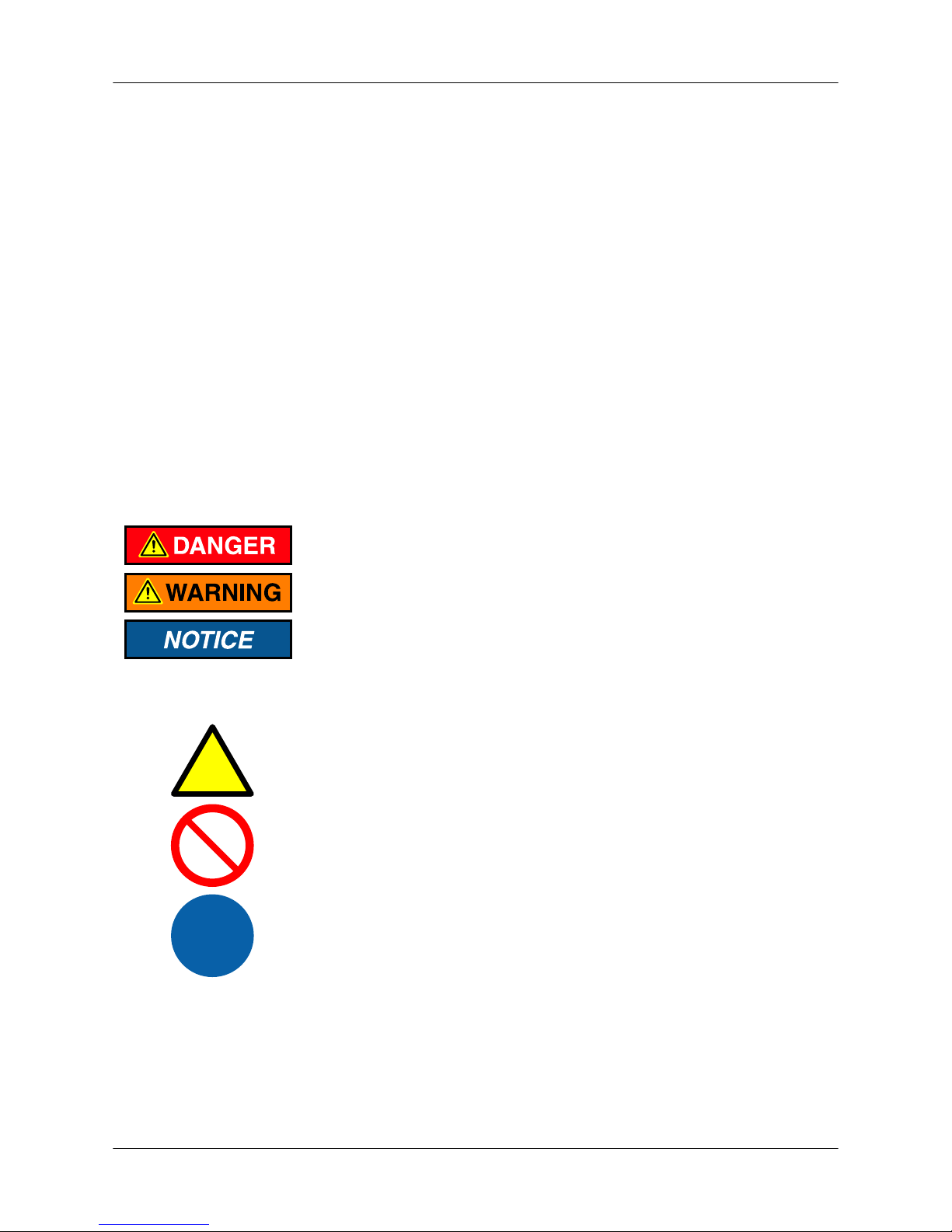
2.1. Hazard levels
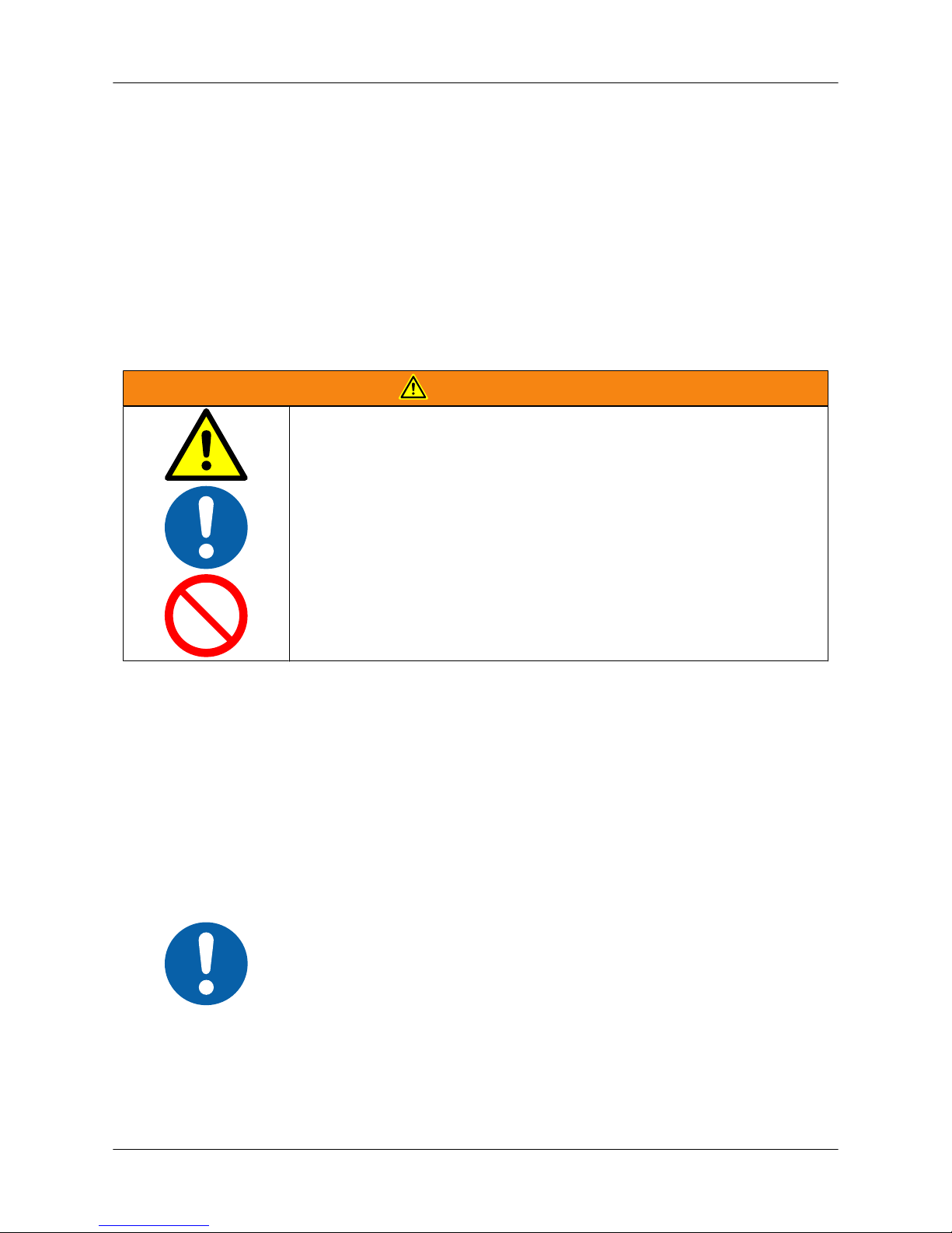
The term DANGER indicates a hazardous situation which, if not avoided,
will result in death or serious injury.
The term WARNING indicates a hazardous situation which, if not avoided,
could result in death or serious injury.
The term NOTICE indicates a hazard with a risk which, if not avoided, could
result in property damage.
2.2. Safety symbols
Warning
A yellow triangle with a black border and black symbol indicates danger.
Prohibition
A round sign with red border, cross-line and black symbol indicates that the
action in question is prohibited.
Compulsory action
A blue circle with a white symbol indicates that the action in question must
be carried out in order to avoid hazard.
User Guide - E5 Turret Punch Press
6 (46)
Page 7
2.3. Safety during operation and maintenance
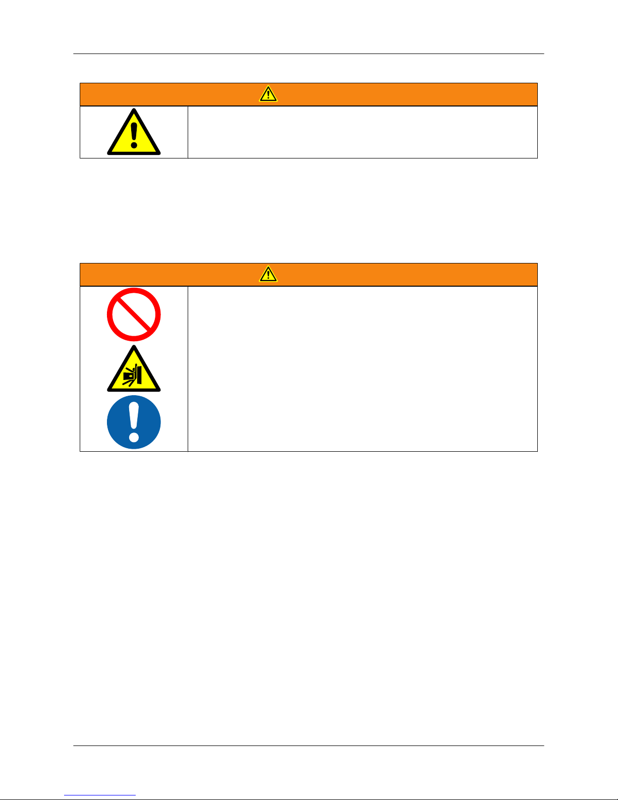
WARNING
The machine must not be taken in production use before it has
been installed according to the layout and tested and handed
over to the customer according to the delivery contract.
2.3.1. Operation stations and safety zones
• During operation, the operator is normally stationed at the control panel / control desk.
• The machine's working area is surrounded by a safety zone.
• The safety zone is separated by fixed structures, safety fences and safety devices.
• The machine may be left running in automatic mode.
• During machine operation no one, including the operator, is allowed within the safety zone.
WARNING
• Do not store goods or products in the safety zone.
• Crushing hazard; the working movements of the machine and
the machined part present a serious risk of accident
• When starting the machine, always ensure that no people nor
foreign objects are within the safety zone.
User Guide - E5 Turret Punch Press
7 (46)
Page 8
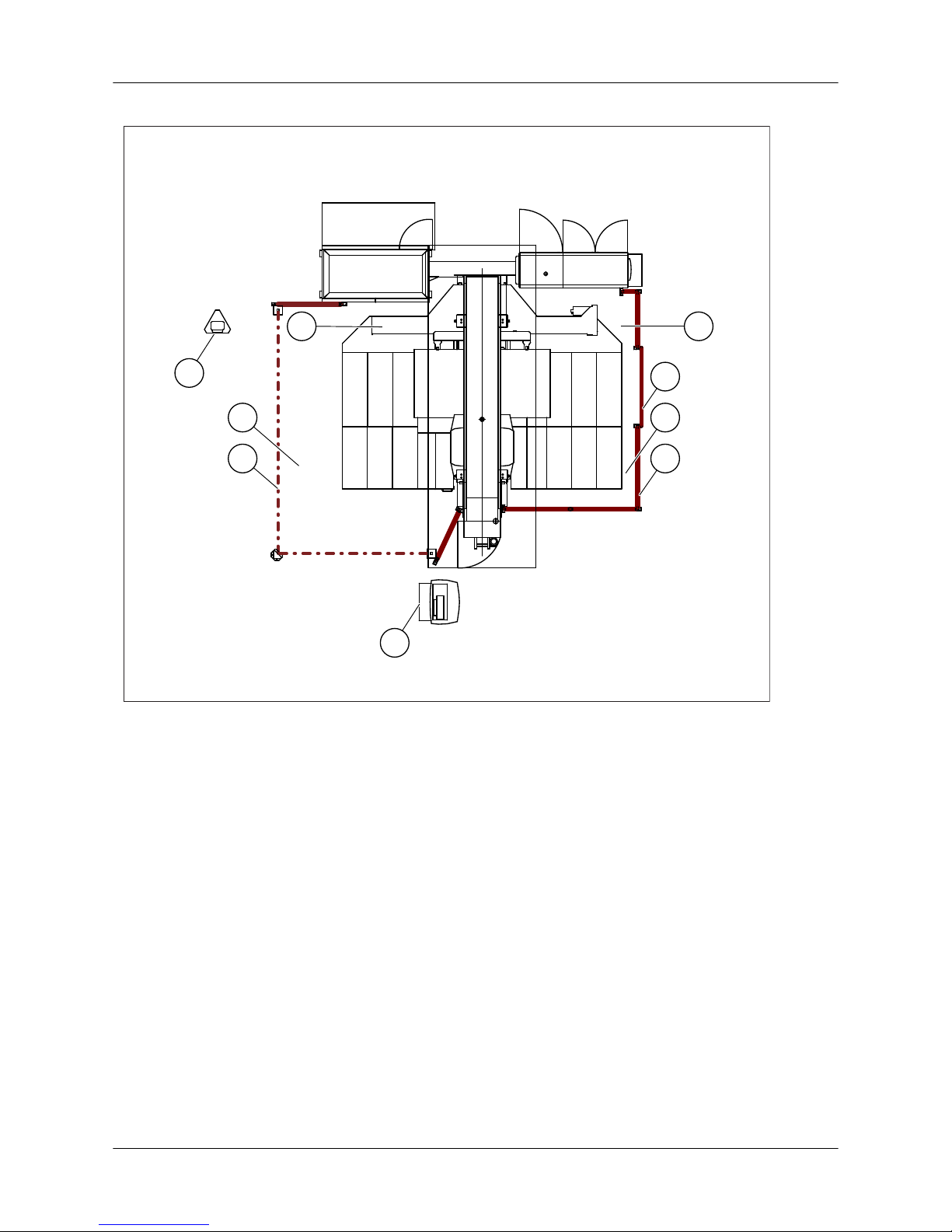
Operation stations and safety zones (E5/C5)
1
2
BA
4
6
3
5
3
Machine operating sides A and B
1. Control desk (operation station 1)
2. Remote control panel (operation station 2)
3. Safety zone
4. Safety fence
5. Safety light beam
6. Service door
2.4. Safety devices and functions of the base machine
The machine delivery includes the following safety devices and functions that trigger alarms and stop
the machine when necessary:
• Emergency stop buttons
• Safety limit switch for the turret service door
• Safety limit switch for the service door (option)
• Safety light beams
In addition, the machine is equipped with the following safety functions to protect it from damage:
1. Central locking and protection area control for clamps
2. Sheet detectors in clamps
User Guide - E5 Turret Punch Press
8 (46)
Page 9
3. Extreme limits of axis movements
4. Pressure switch for compressed air supply
5. Overload protection of the servo motor (in connection with upforming mechanism)
6. Supply voltage control
7. Operating temperature control for the NC control unit
8. Punch stripping control
9. Locking control of the auto-index system
10. Sheet distortion limit switch
2.5. Periodic inspection of safety devices
To ensure reliable and safe operation of the machine, periodic inspection of the machine's safety
devices must be performed. Carry out the inspections according to the following instructions.
WARNING
• TBy-passing a safety device is strictly forbidden.
• Repair any faults or defects detected during inspection immediately, or contact Finn-Power service.
• The machine must not be used until all detected faults have
been repaired.
2.5.1. Safety light beams
Check the safety light beams once a day
Check the safety light beams (option) on the A and B sides as follows:
• Check that the safety light beam is mounted securely.
• Check that the safety light beam is undamaged.
• Check that the surfaces of the safety light beams are clean.
With the machine running, interrupt the light beam. When the light beam is interrupted, check that
1. the axis movements of the machine stop
2. blue indicator light lights up on the reset button of the A-side remote control panel
3. blue indicator light lights up on the B-side reset button
If the light beam is interrupted, the machine cannot be operated
in automatic mode.
User Guide - E5 Turret Punch Press
9 (46)
Page 10
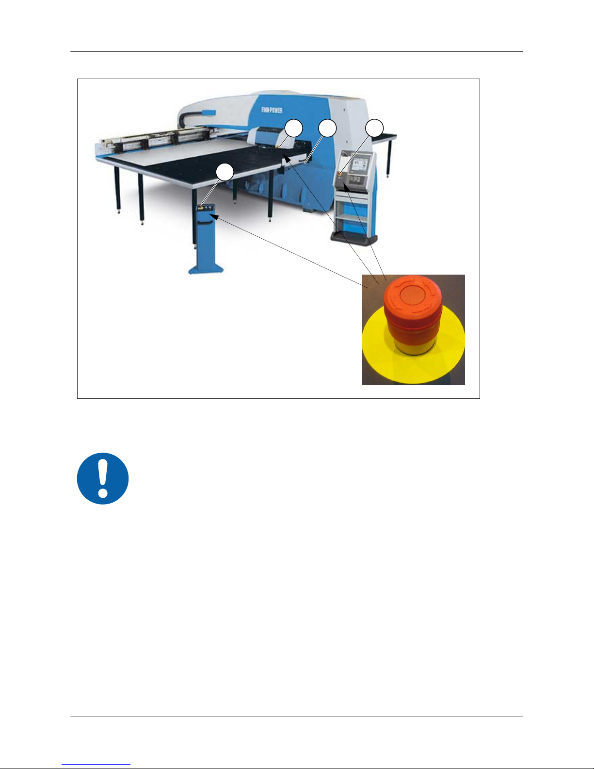
2.5.2. Emergency stop buttons and turret service door
21
1
1
Figure: Emergency stop buttons and turret service door
1. Emergency stop buttons (control desk, remote control panel, turret cover)
2. Turret service door
The delivery may also include other emergency stop buttons.
Check the emergency stop buttons once a month
Check that
• the button is easily accessible
• the button is clean and easy to see
• the body of the button is properly attached to its mounting tray
• the button part is not loosened or detached from its shank
• the button is not damaged by dents (e.g., cracked)
• there is no dirt between the moving parts of the button
• the button release is not over-sensitive
• the button locks reliably in the open position.
With the machine running, press down the emergency stop button.
Check that
User Guide - E5 Turret Punch Press
10 (46)
Page 11

1. the axis movements of the machine stop
2. the green indicator light on the control desk goes out
3. the value on the pressure gauge of the machine's service unit (PN1) changes to 0 bar.
Use the emergency stop button only in hazardous situations.
Check the turret service door once a month
Check that
• the safety limit switch is mounted securely
• the sensing surfaces of the safety limit switch are clean
• the safety limit switch is not damaged by dents
• the service door locking mechanism functions properly.
Open the turret service door, exit the safety zone, and reset the safety devices. Check that X and Y
movement of the machine is not possible.
2.5.3. Hydraulic and pneumatic system
Check the hydraulic system once a month
Check the hydraulic system in connection with turret service door checking. Check the control panel
of the machine to ensure that there is no pressure in the hydraulic system when the service door is
open.
Check the pneumatic system once a month
Check the pneumatic system in connection with an emergency stop. Check that the value on the
pressure gauge of the machine's service unit (PN1) changes to 0 bar.
2.5.4. Service door
Check the service door (option) safety limit once a month
Check the safety limits of the service doors:
• Check that the service doors are mechanically in good condition.
• Check that the limit switch is mounted securely.
• Check that the sensing surfaces of the limit switch are clean.
• Check that the limit switch is not damaged by dents.
Open the service door. Check that
1. the axis movements of the machine stop
2. blue indicator light lights up on the control box button next to the service door.
2.5.5. Warning and instruction labels (E5/E5x/E6/E8)
• 003319
User Guide - E5 Turret Punch Press
11 (46)
Page 12
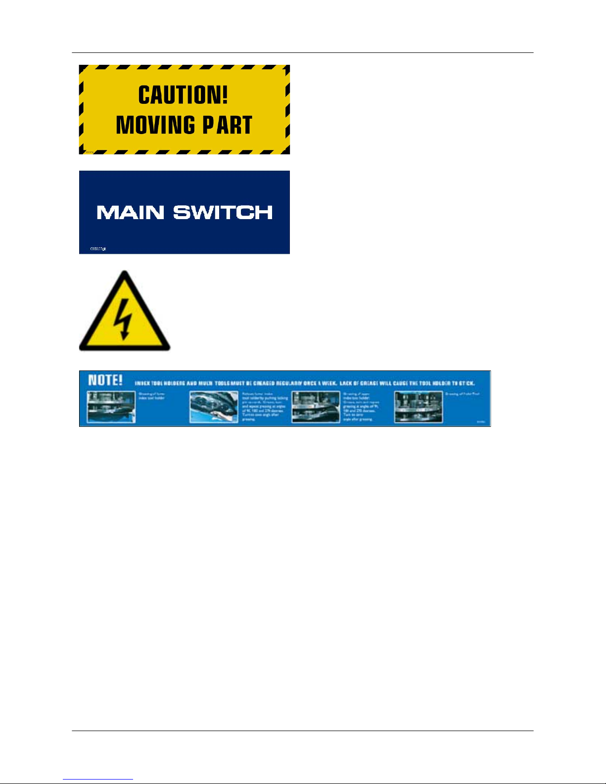
• 003147
• 003027
• 003002
• Indicates an electrical hazard
• 003378
• Indicates the weekly maintenance points of the
index tool holders and Multi-Tools
User Guide - E5 Turret Punch Press
12 (46)
Page 13

3. Technical information, E5/E6/E8
Performance
Ram force 200 kN / optional 300 kN (later upgrading is possible)
Punching stroke electrical servo motor
Tool stations in the turret 20
Tools Thick Turret
Max. punch diameter 89 mm
Clamps, pneumatic 2 pcs / optional 3 pcs (E5) 3 pcs / optional 4 pcs (E6/
E8)
Turret rotation 23.8 r/min (E5) 30 r/min (E6/E8)
Tool change time
(1)
1–3 s
Auto-index system:
• Index tool stations standard 2 pcs / max. 10 pcs
• Max. punch diameter 89 mm
• Max. tool rotation 166 r/min
Indexable upforming system (option):
• Upforming force 200 kN
• Die stroke height in forming programmable by increments of 0.001 mm (max. 12
mm; NC axis)
• Upforming speed with 25 mm form-to-
form distance
(2)
80–150 1/min
E5 E6/E8
X-traverse 2584 mm 3144 mm
Max. X-traverse, axis speed 90 m/min 120 m/min
Y-traverse 1317 mm 1615 mm
Max. Y-traverse, axis speed 60 m/min 90 m/min
Max. positioning speed 108 m/min 150 m/min
Max. hit speed
(3)
:
E5 E6/E8
• 1 mm between holes
• 25 mm between holes
• 250 mm between holes
800 1/min
430 1/min
160 1/min
900 1/min
-
-
Punching accuracy according to LKP-7100
(4)
:
• Max. hole location deviation (X/Y axis) 0.1 mm
• Max. hole-to-hole distance deviation (X/Y
axis)
+/- 0.05 mm
• Max. angular deviation (CNC Index Tool) +/- 0.1°
Positioning accuracy according to VDI/DGQ 3441
(5)
:
• Positional deviation, Pa (X/Y axis) 0.08 mm (+/- 0.04 mm)
• Positional scatter, Ps (X/Y axis) 0.04 mm (+/- 0.02 mm)
Sheet dimensions
Max. sheet size X x Y 2530 mm x 1270 mm (E5) 3074 mm x 1565 mm (E6)
4300 mm x 1565 mm (E8)
Max. sheet weight
(6)
200 kg
User Guide - E5 Turret Punch Press
13 (46)
Page 14

Max. sheet thickness 8 mm
Connections
Electrical connection (E1):
•
Average power consumption
(7) 5 kVA / 4 kW
•
Power requirements
(8) 11 kVA
• Min. fuse size 16 A
Compressed air connection (P1):
• Min. compressed air pressure 6 bar
• Max. compressed air consumption 5 Nl/s
•
Average compressed air consumption
(9) 2.5 Nl/s
Ethernet connection 100 Mbps yes
Additional data
Work chute (option), max. part size 500 mm x 500 mm
NC control Siemens Sinumerik 840D
Program memory 1.5 MB
Machine weight 12 500 kg (E5) 13 500 kg (E6/E8)
Painting two-component acrylic polyurethane paint and epoxy/
polyester powder paint
Colours: blue RAL 5015
grey Tikkurila TVT 854H (AKZO 160 A1)
yellow RAL 095 90 59
black RAL 9011
Gloss grade: 85% epoxy/polyester powder paint
90% two-component polyurethane paint
Noise sound pressure level may exceed 85 dB (A)
3.1. Notes on technical information
(1) When special tools are used, the tool change time may differ from the value given.
(2) Upforming speed depends on the form height, ram speed, acceleration/deceleration rate of
the X and Y axes, and axis speed.
(3) Hit speed depends on the programmed stroke length, ram speed, and acceleration/
deceleration rate and speed of the axes.
(4) Punching accuracy is tested according to the Finn-Power standard LKP-7100 by punching
holes in a 1 m x 1 m sheet at 100% speed and measuring the location (X/Y) and angle (CNC
Index Tool) of the holes punched in the sheet.
(5) Positioning accuracy is measured by a laser-interferometer from the X and Y slides of the
machine's coordinate table according to the VDI/DGQ 3441 standard.
(6) The allowable acceleration/deceleration rate of the X and Y axes depends on sheet weight.
Part accuracy depends on the acceleration/deceleration rate and on the sheet size and weight.
(7) Average power consumption is based on the production run of a typical nesting program with
nominal sheet size and 1.5 mm sheet thickness. The effective value can be used in calculation
of energy costs.
(8) This value must be used when the power supply is dimensioned for the machine (size of
possible transformer and cable).
User Guide - E5 Turret Punch Press
14 (46)
Page 15

(9) Average compressed air consumption is based on the production run of a typical nesting
program with nominal sheet size and 1.5 mm sheet thickness. The value can be used in
calculation of energy costs.
We reserve the right to change technical specifications without prior notice.
User Guide - E5 Turret Punch Press
15 (46)
Page 16

4. Operating description of turret punch press
The turret punch press is constructed for processing of sheet material. Tools for punching are located
on the turret. Sheets are processed by punching them with a punch and die. In the process the sheet
is moved according to NC control commands. Punching can be executed as a single stroke or a stroke
sequence (nibbling or cutting out).
The machine is constructed to be suited to its purpose of use and to be operated, adjusted and
serviced without exposing people to danger as far as the operations in question are performed in the
way the manufacturer has intended and in accordance with the manufacturer's instructions.
4.1. Misuse of the machine
The machine must not be used for any other purpose than for processing of sheet material. The
operating values specified in the technical data must not be exceeded. Neither the application, the
construction or any part thereof must be changed nor any auxiliary equipment added without a written
consent from the manufacturer.
User Guide - E5 Turret Punch Press
16 (46)
Page 17
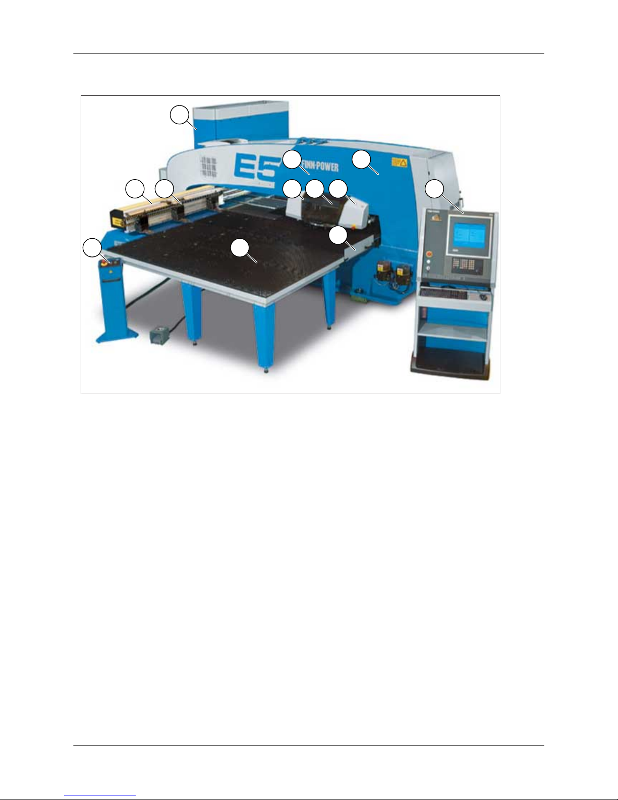
5. Main structure of the machine E5
10
2 9
1
511
8
12
6
4
7
3
1. Frame
2. Turret
3. Coordinate table
4. Clamps
5. Brush tables
6. Punching mechanism
7. Control centre
8. Turret cover
9. Manual turret rotation push-buttons
10. Control desk
11. Remote control panel
12. Turret service door
5.1. Machine axes
• Three linear axes for X, Y, and RAM movements
• Two rotating axes (0 to 360°)
• C for index
• TUR for tool change
Options
• TU axis for TU6 tapping unit
• FORM axis for upforming
5.2. Coordinate table
• The coordinate table moves the sheet in the X and Y axis directions, being controlled by the
NC control. Axis speed is freely programmable.
• Axis acceleration can be reduced by programming.
• The working area in the X-direction can be expanded automatically by means of the repositioning function.
User Guide - E5 Turret Punch Press
17 (46)
Page 18
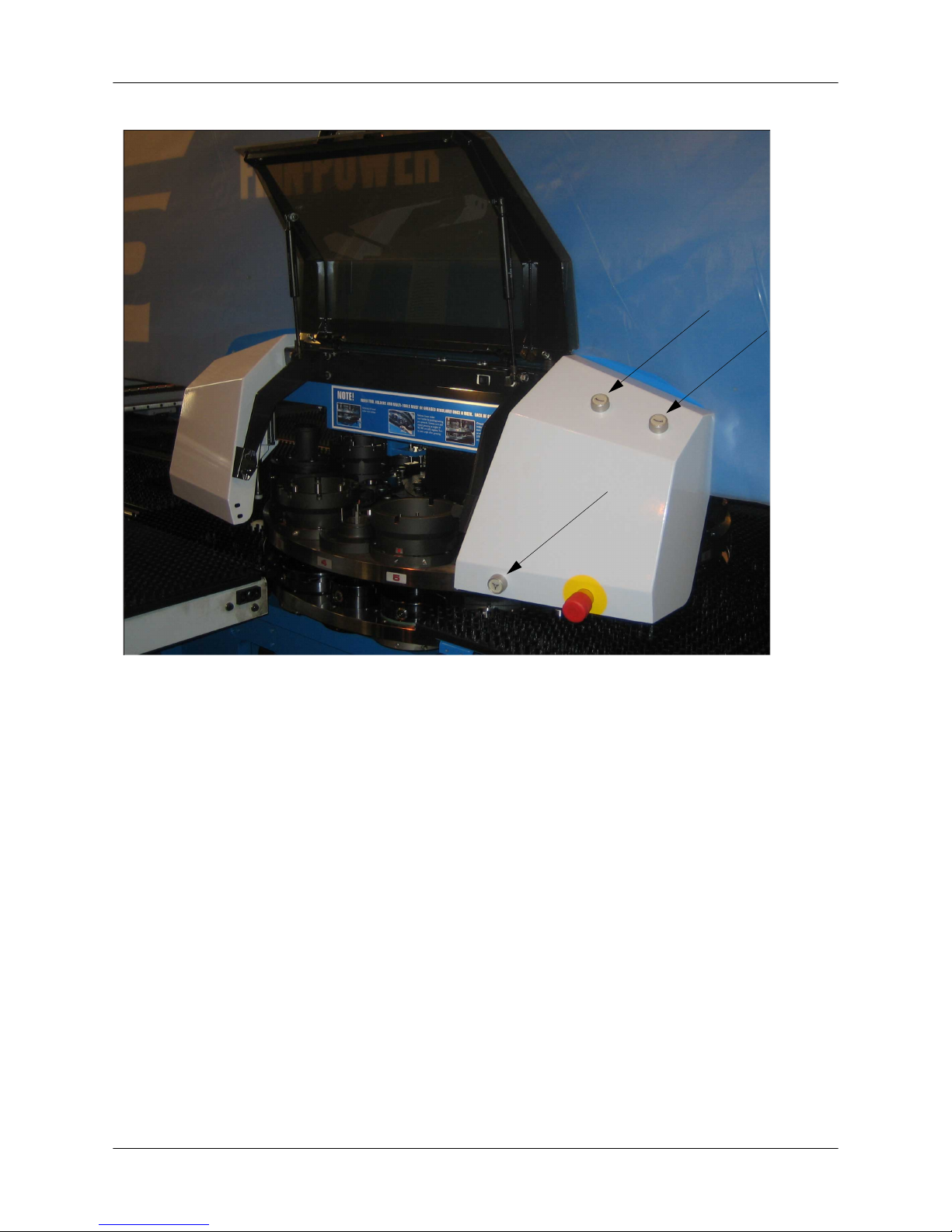
5.3. Turret
Figure: Turret
• The machine comes with a 20-station turret.
• The turret is completely protected by cover plates.
• The turret comes with separate tool holders, which allows making the turret layout to customer
specification.
• The tool holders are easy to change.
• There is a service door in the brush table to give access to the turret.
• The turret can be rotated manually by pressing the buttons in the turret cover when the turret
service door is open.
• The buttons are operational only in JOG mode.
• When the turret service door is open, other axes cannot be moved.
User Guide - E5 Turret Punch Press
18 (46)
Page 19
7
3
4
11
1
5
10
2
6
9
8
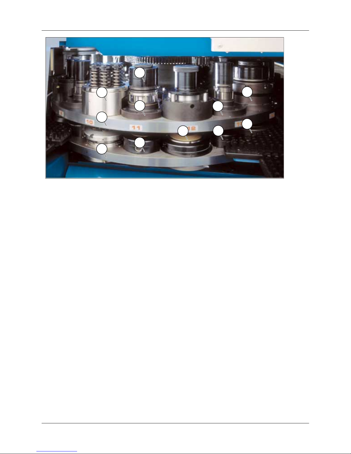
Figure: Turret tools
1. Upper turret plate
2. Lower turret plate
3. Tool holder, upper (B)
4. Tool holder, lower (B)
5. Tool holder, upper (C)
6. Tool holder, lower (C)
7. Index tool holder, upper (Di)
8. Index tool holder, lower (Di)
9. MT6-A/135
Interchangeable tools
10. Tool assembly
11. Die
5.4. Clamps
• The clamps are equipped with a pneumatic central locking system.
• All punch presses have connectors for the installation of an additional clamp (option).
• The programmable clamp setting system (PCS) positions and locks the clamps in the positions
defined in the NC program.
• NC control measures the clamp positions and controls automatically that the clamps do not
collide with anything.
5.5. Brush tables
• The brush table damps sheet vibration and noise, and it does not damage the underside of the
sheet.
• The table on the loading side is equipped with sheet support rollers which rise when a sheet is
being loaded. Thanks to the rollers, it is easy to load sheets and insert them between the clamps.
When the clamps are closed, the sheet support rollers retract automatically.
• The brush table can be equipped with a work chute (option) in front of the turret through which
the parts are dropped from the table to be sorted.
User Guide - E5 Turret Punch Press
19 (46)
Page 20

5.6. Punching mechanism, E machines
• The punching stroke is generated by a servomotor-driven mechanism.
• The upper and lower limits of the punching stroke can be set numerically (NC axis).
• In forming, the upper and lower limits of the ram are freely adjustable from the bottom position
up.
• With forming tools, you can program a lower ram speed and use a lower forming speed and a
positioning tolerance based on the G code, which allows making exact and intricate shapes.
5.7. Control centre
• The control centre accommodates the central processing unit of the NC control, the servo amplifiers, the cell control computer, and other electrical equipment.
• The computer in the control centre is equipped with a LAN connection.
• The NC control display, the main operation panel of the machine, and the touch screen are
located in a separate control desk.
5.8. Auto-index system
• The auto-index system enables automatic rotating of the tool in the working position according
to the numerical control.
• It is possible to perform punching strokes and nibbling with the tool at a freely programmable
angle.
• The system turns the tool automatically to the programmed angle while the X and Y axes of the
machine move the sheet.
• The index mechanism is mounted on the machine frame, due to which the index tool stations
in the turret are uncomplicated and interchangeable.
• A desired number of index tool stations can be mounted on the turret; the number of stations
can flexibly be changed afterwards.
5.9. Standard tool system Thick Turret
The standard tool system of a turret punch press is Thick Turret (AM). The turret punch press can
also be equipped with other tools to special order.
AM = Thick Turret (Wilson Tool Int. Inc. USA / MATE Precision Tooling, USA)
Tool holders for 110 mm holes
Fixed Thick Turret tool Max. punch diameter
A A (0.5 in) 12.7 mm (0.50 in)
B B (1.25 in) 31.75 mm (1.25 in)
C C (2 in) 50.8 mm (2.00 in)
Tool holders for 135 mm holes
Fixed Index station Forming station Thick Turret
tool
Max. punch diameter
B/135 Bi Bif B (1.25 in) 31.75 mm (1.25 in)
C/135 Ci Cif C (2 in) 50.8 mm (2.00 in)
D Di Dif D (3.5 in) 88.9 mm (3.50 in)
E E (3.5 in) 88.9 mm (3.50 in), CLUSTER
punching area D118 mm
User Guide - E5 Turret Punch Press
20 (46)
Page 21
• When a normal punching tool is used in a forming station, an adapter part is necessary for
mounting the die on the forming station.
• In a Dif forming station, the max. diameter of a punching tool (scrap piece) is 50 mm (2 in).
• Forming station Dif can be mounted only on turret stations No. 3, 7, 11, 15 and 19.
• E-tool can be mounted only on turret stations No. 5 or 5 and 13, which have been specifically
machined for it (Ø 143 mm).
• The diameter of a CLUSTER punching area is 118 mm, but the max. part size in the tool station
is 88.9 mm.
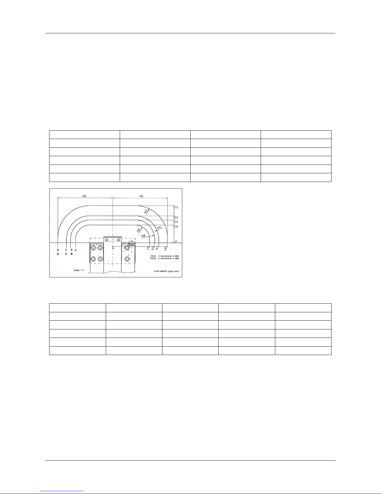
5.9.1. Clamp protection areas
X Y R
A 73 35 28
B 83 45 38
C 91 53 46
D 108 73 63
E 130 93 83
Thick Turret (AM)
Tool size X (mm) Y (mm) X (in) Y (in)
A 73 35 2.87 1.38
B 83 45 3.27 1.77
C 91 53 3.58 2.09
D 108 73 4.25 2.87
E 130 93 5.12 3.66
User Guide - E5 Turret Punch Press
21 (46)
Page 22
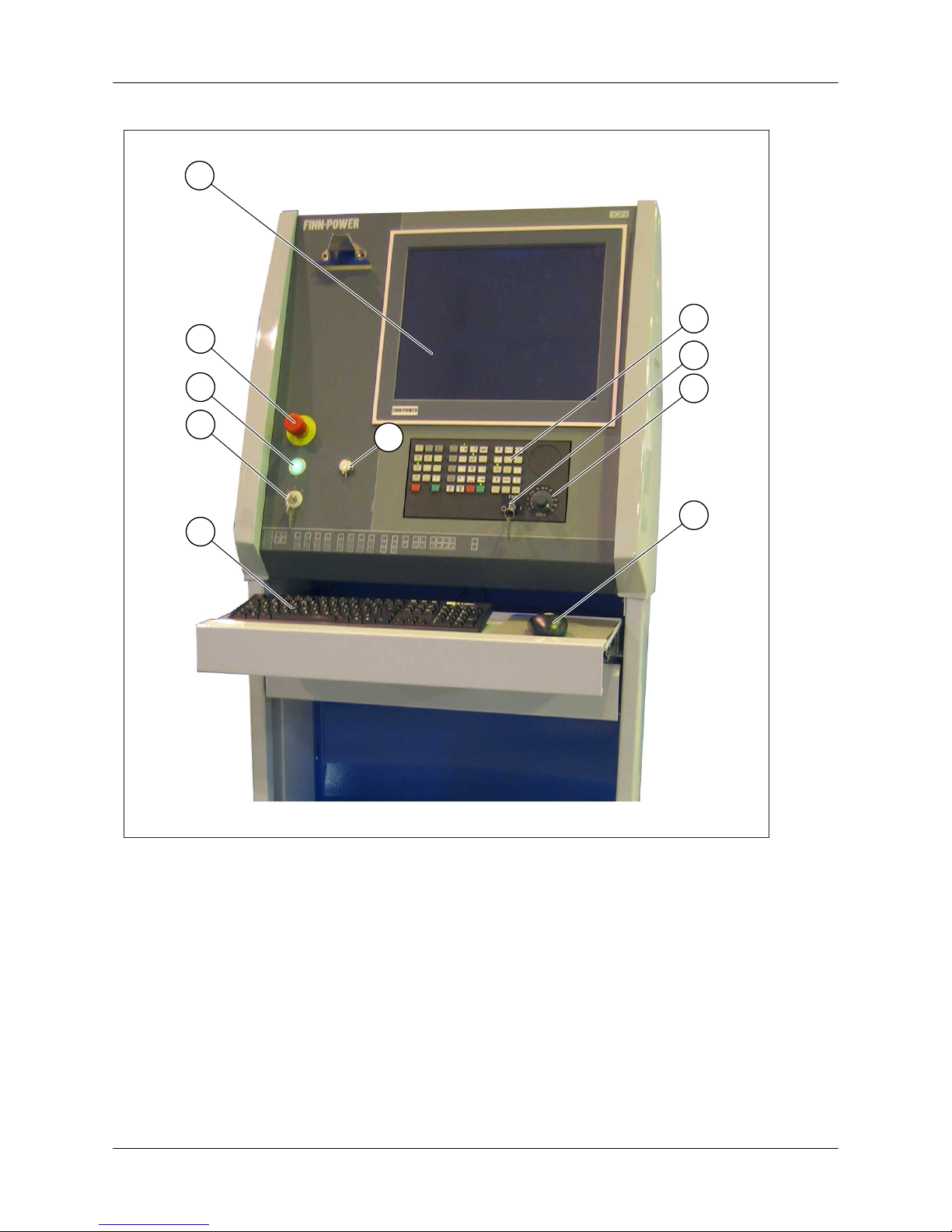
5.10. Control desk (Siemens)
2
1
4
3
5
7
6
10
8
9
1. Touch screen (industrial PC)
2. Emergency stop button
3. Control voltage indicator light
4. Control voltage key switch
5. Alphanumeric keyboard
6. Mouse or other pointing device
7. Feed rate switch
8. FMM on/off switch
9. Machine control panel
10. USB connection
User Guide - E5 Turret Punch Press
22 (46)
Page 23
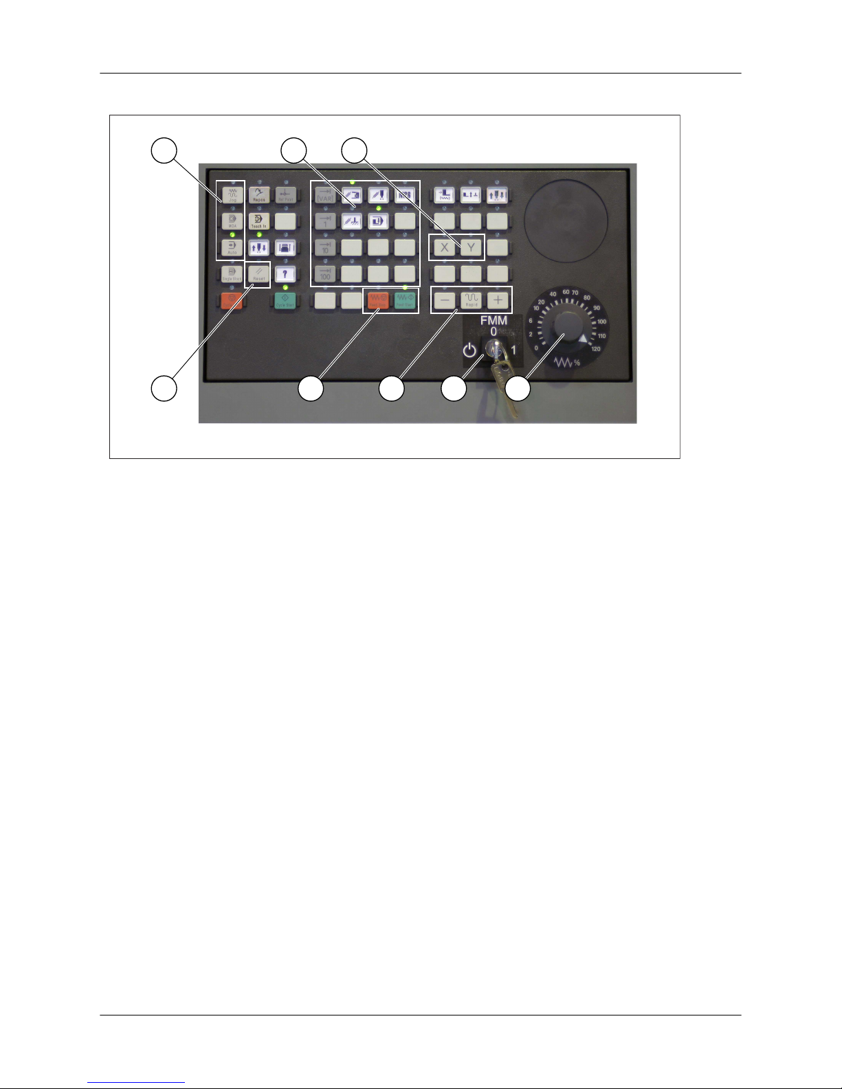
5.11. Control panel (Siemens)
1 2 3
4 5 876
1. Mode selection
2. Machine function keys
3. Axis selection buttons
4. RESET button
5. FEED START and FEED STOP
6. Direction buttons
7. FMM on/off switch
8. Feed rate switch
User Guide - E5 Turret Punch Press
23 (46)
Page 24
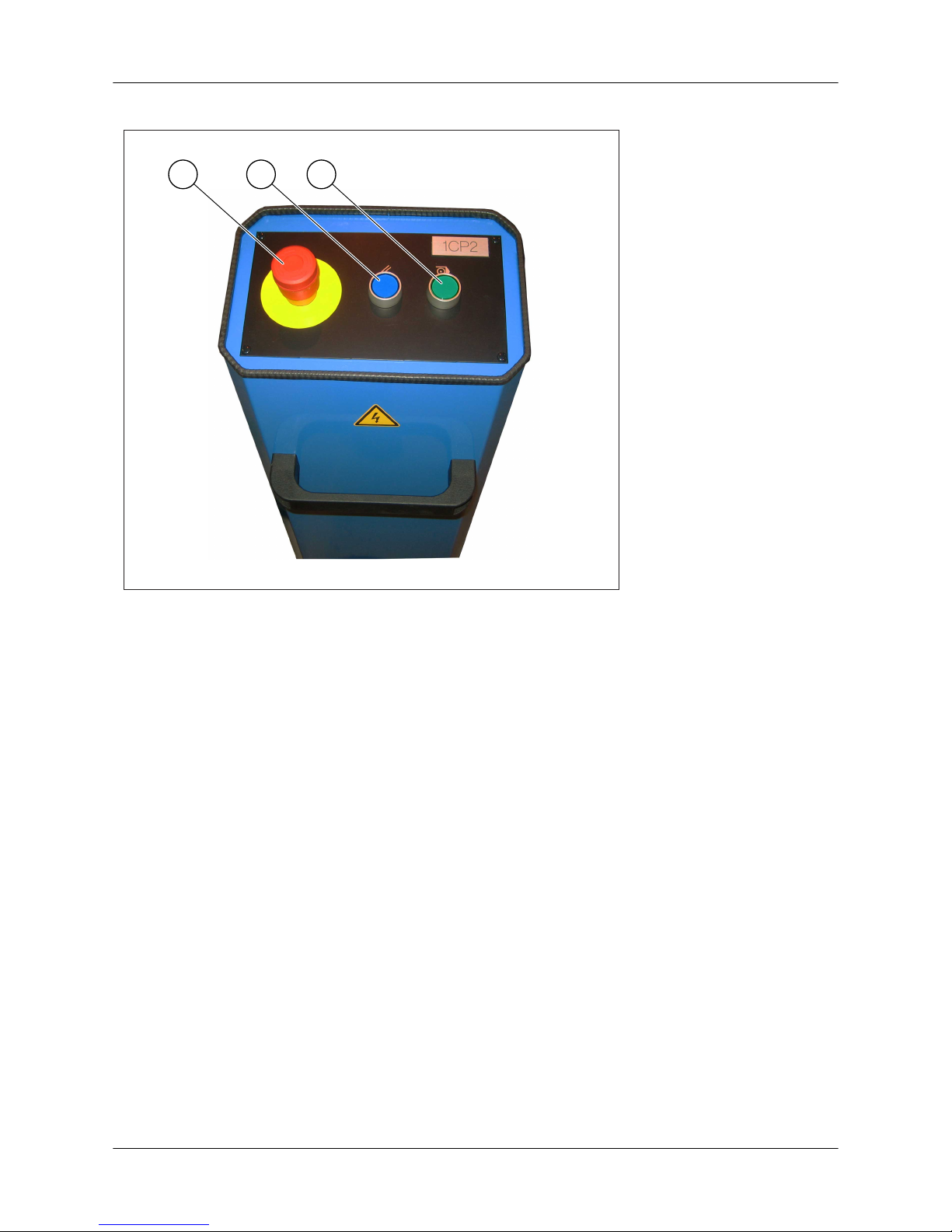
5.12. Remote control panel
1 2 3
1. Emergency stop button
2. Reactivate button for safety light beams
3. CYCLE START (program start)
User Guide - E5 Turret Punch Press
24 (46)
Page 25
6. Using the machine
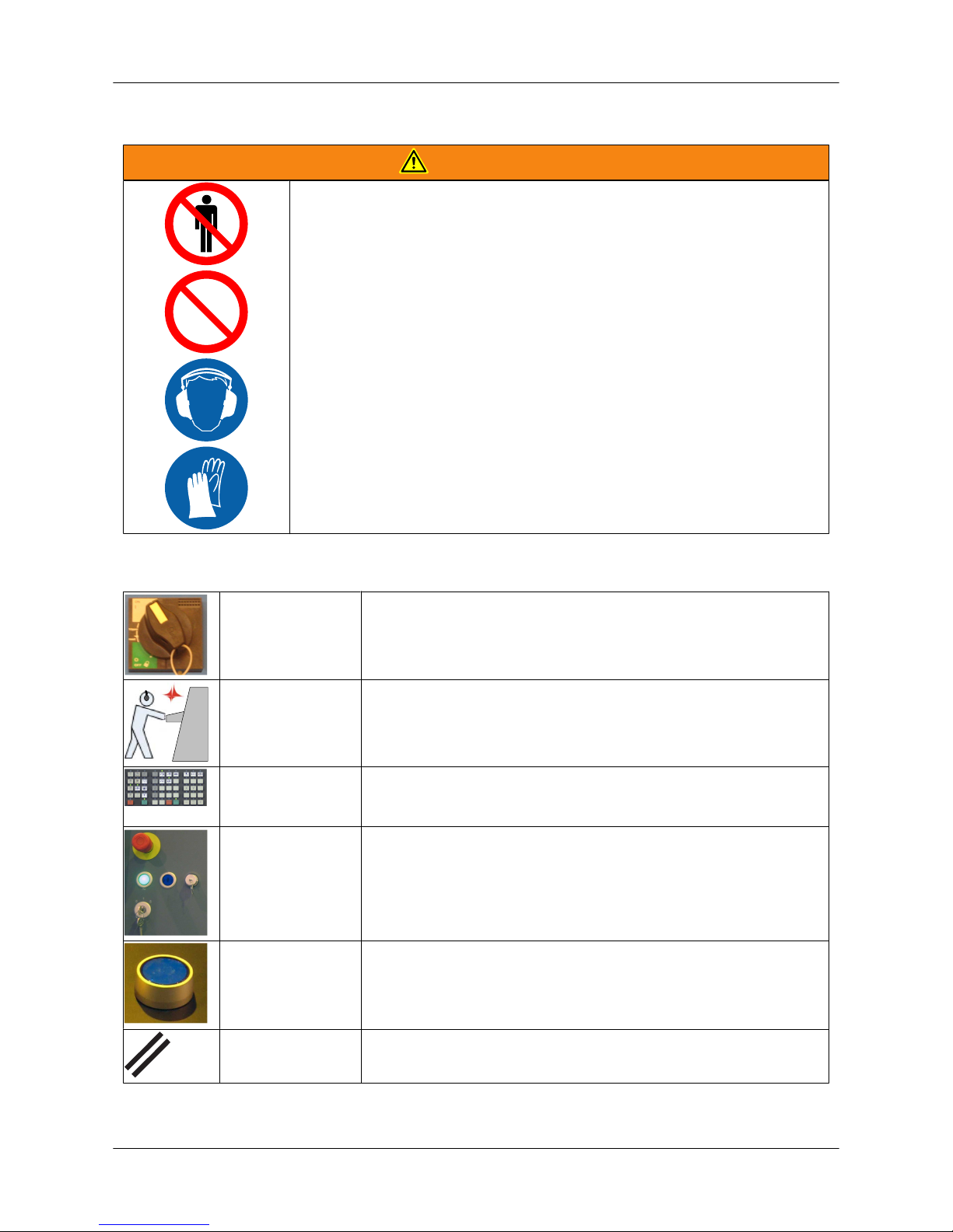
WARNING
• Make sure that there are no foreign objects or no one within the
safety zone or on top of the machine.
• Always use hearing protectors.
• When necessary, use personal protective equipment, such as
safety gloves, safety shoes, etc.
• It is strictly forbidden to operate a machine which is out of order.
6.1. Starting the machine and emergency stop
MAIN SWITCH Switch on the current from the main switch (in the control cabinet
door).
COMPUTER Switch on the computer.
INDICATOR
LIGHTS
Indicator lights in the machine's control panel start to blink. Wait
until the indicator lights no longer blink. Then, the control system
has started.
CONTROL
VOLTAGE
Switch on the control voltage with the key switch (on the left in the
control desk).
• The green indicator light is lighted when the control voltage is
on.
SAFETY
CIRCUITS
Activate the safety circuits:
• safety light beams
• electric locks
RESET Press the RESET button to reset the alarms.
User Guide - E5 Turret Punch Press
25 (46)
Page 26
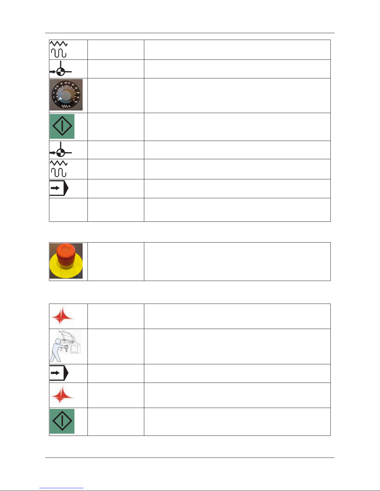
JOG Select JOG mode.
REF Select reference point approach.
FEED RATE Turn the feed rate switch from zero to a desired feed rate:
• recommended rate 100%
• in position 0%, the axes do not move.
CYCLE START Press the CYCLE START button to start referencing.
REF Wait until referencing is completed. Each axis reaching the
reference point is seen on the machine display.
JOG Select JOG mode again. (Stops the REF function.)
AUTO Select a mode you want to use, e.g. automatic mode.
HYDR
ON
HYDR ON Switch on the hydraulics (C5/C6/C8/SG).
Stopping the machine in an emergency
EMERGENCY
STOP
Press the emergency stop push-button in an imminent hazardous
situation:
• danger of personal injury
• danger of machine damage
6.2. Production order run
TULUS Select a desired production order and/or add a production order to
the task list (Tulus/Production order button).
TOOLS Check the tools in the turret and the Tulus tool settings.
AUTO Check that AUTO mode has been selected.
START Start processing (Tulus/Start processing button).
CLAMP SETTINGS Press the CYCLE START button.
• Clamp settings are performed automatically.
User Guide - E5 Turret Punch Press
26 (46)
Page 27
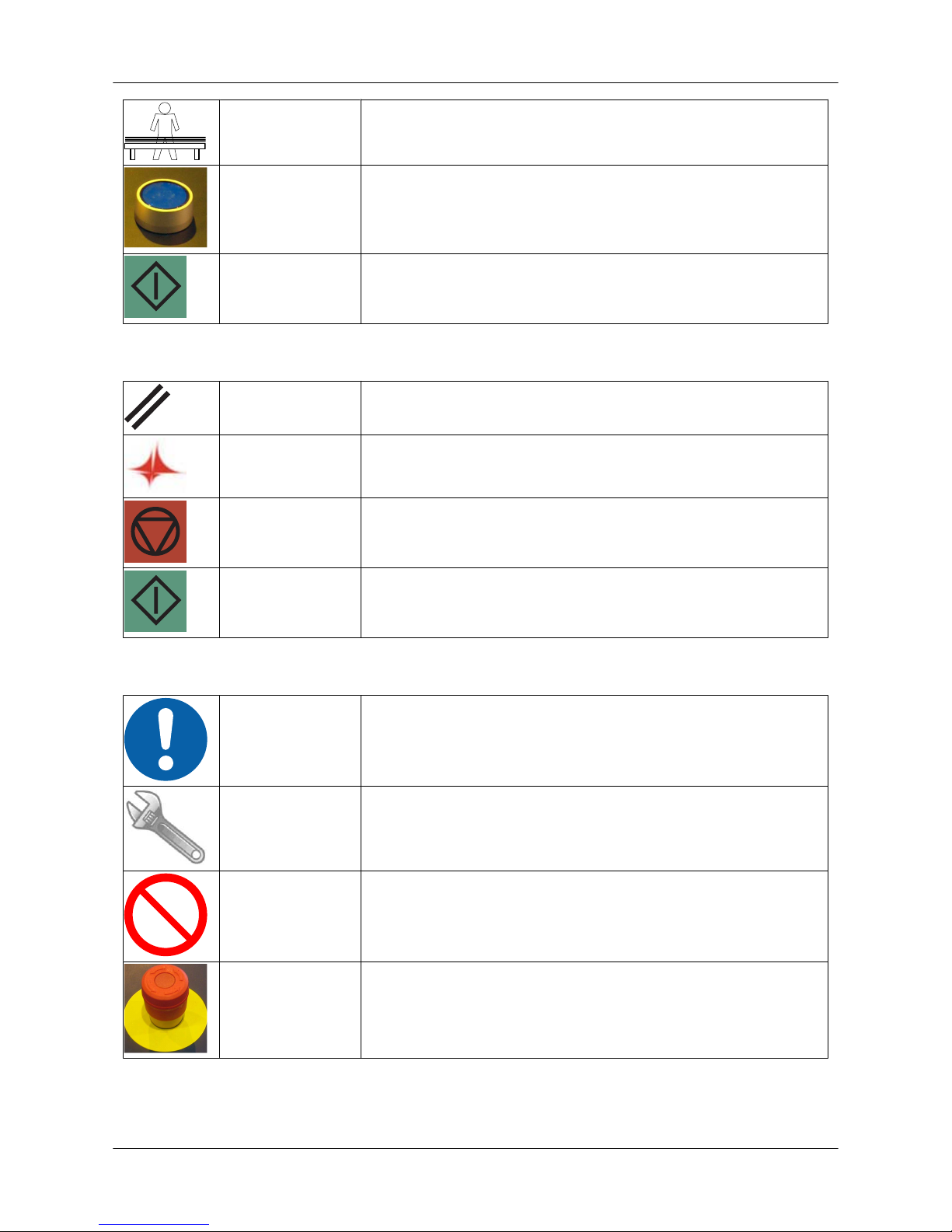
SHEET Feed a sheet between the clamps (unnecessary in automated
operation).
SAFETY
CIRCUITS
Activate the safety circuits (unnecessary in automated operation):
• safety light beams
• electric locks
PROGRAM START Start the program run by pressing the CYCLE START button
(unnecessary in automated operation).
6.3. Production run control
PROGRAM
INTERRUPTION
Interrupt the program by pressing the RESET button.
RESTART Restart the program after an interruption (Tulus/Restart button).
PROGRAM STOP Stop the program by pressing the CYCLE STOP button.
CONTINUING
AFTER A STOP
Continue the program from the same point by pressing the CYCLE
START button.
6.4. Production run after emergency stop
REASON Establish the reason for the emergency stop. The reason can be a
mechanical breakdown or personal injury.
REMEDY Eliminate the reason for danger and/or repair the defect you found.
RESTART Do not release the emergency stop button or restart the machine
if you have not eliminated the reason for danger or repaired the
defect you found.
RELEASE Release the emergency stop button.
User Guide - E5 Turret Punch Press
27 (46)
Page 28
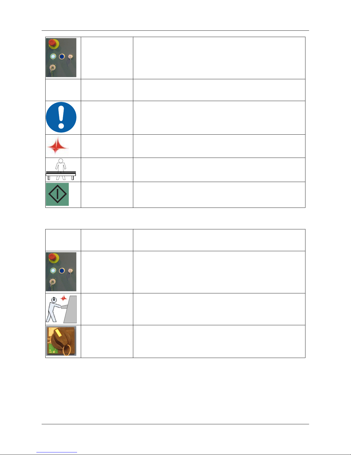
CONTROL
VOLTAGE
Switch on the control voltage with the key switch.
HYDR
ON
HYDR ON Switch on the hydraulics (C5/C6/C8/SG).
CHECK Check the condition of the sheet.
RESTART Continue to run the program if the sheet has not been damaged
(Tulus/Restart button).
SHEET Replace the sheet if it has been damaged.
START Start the program from the beginning.
6.5. Shutting down the machine in a normal situation
HYDR
OFF
HYDR OFF Switch off the hydraulics (C5/C6/C8/SG).
CONTROL
VOLTAGE
Switch off the control voltage with the key switch.
COMPUTER Close the computer programs and shut down the computer.
MAIN SWITCH Shut down the machine by switching off the current from the main
switch.
6.6. Turret rotation
It is possible to rotate the turret manually with the push-buttons in the turret cover when the turret
service door is open.
• The push-buttons are operational only in JOG mode.
• The ram must be in the upper position when the turret is rotated.
• When the turret service door is open, other axes cannot be moved.
User Guide - E5 Turret Punch Press
28 (46)
Page 29
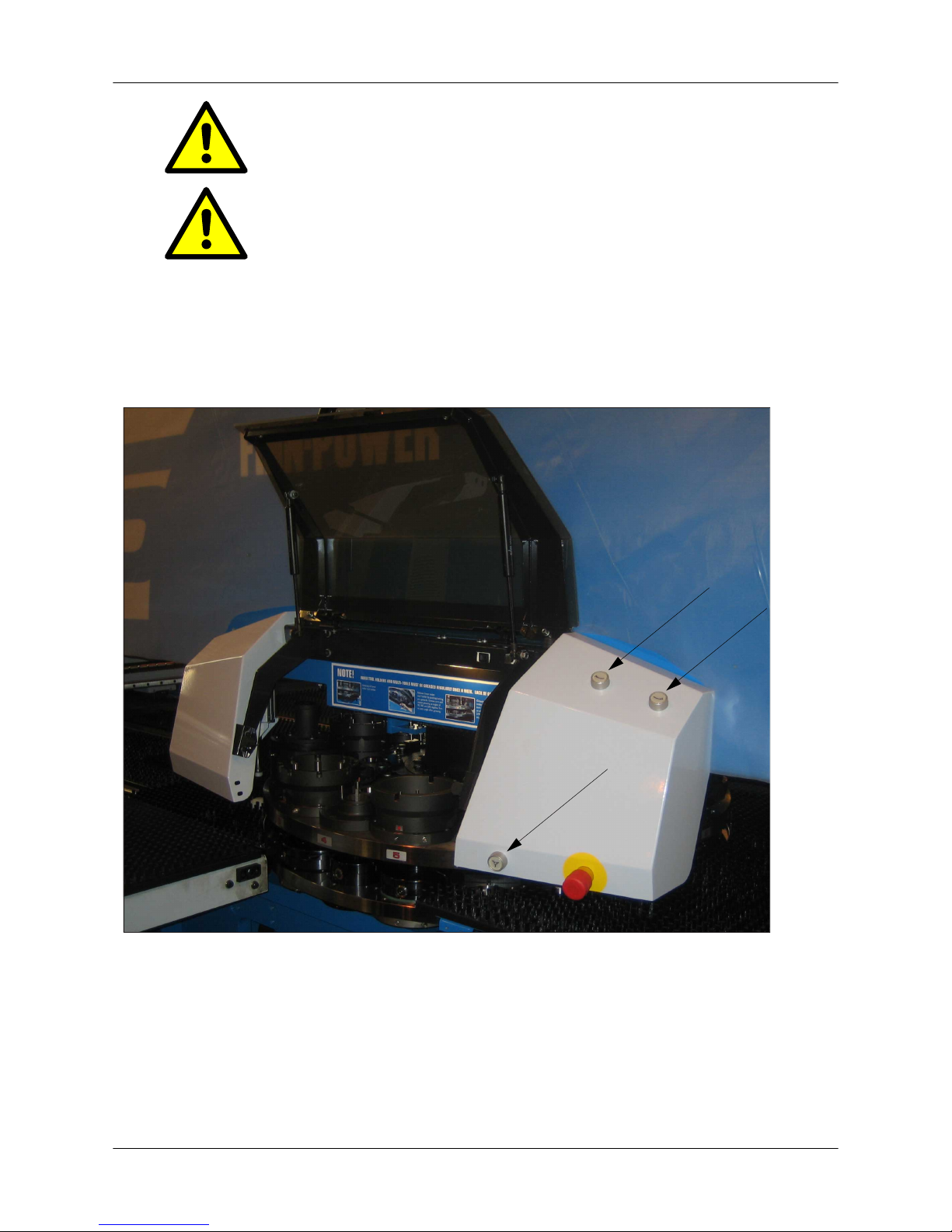
Beware of the rotating turret. Make sure that there are no other
people close to the open turret cover door.
Make sure that there are no loose objects on top of the turret or
between the turret plates.
• Select the rotation direction of the turret with the upper buttons. Start rotating the turret with the
lower button.
• The turret rotates as long as one of the rotation direction buttons and the turret rotating button
are kept depressed simultaneously.
• The turret rotates only if both buttons are depressed within 0.5 seconds.
• Releasing one of the buttons will stop the turret.
Figure: Manual turret rotation push-buttons
6.7. Mounting a tool on the turret
Tool list
• 5-mm Allen wrench
• 6-mm Allen wrench
• lubricating oil for tools and holders
User Guide - E5 Turret Punch Press
29 (46)
Page 30

• lint-free cloth
• wooden hammer shaft or other similar tool
Tool library
• Create the tool in the Tulus tool library if it does not already exist there.
• Move the tool to the turret in Tulus. Select installation angle and die clearance.
• Rotate the desired tool station to the change position
• with the Tool to change position button in MDA mode of Tulus or
• with the manual turret rotation push-button in JOG mode.
• Open the turret service door.
Removing the former tool
Lift the Multi-Tool carefully by the striker so that the Multi-Tool
body does not drop. Only friction keeps the striker fastened by
means of an O-ring.
• Lift the punch straight upwards.
• Unscrew the die clamp screws and take the die out.
• It is often necessary to tap the die from below to make it detach. Use a wooden hammer shaft
or a similar tool. Do not wrench between the die and holder with a hardened screwdriver.
Mounting a new die
• Clean the die holder and clamp carefully with a lint-free cloth.
• If the amount of scrap and dirt between the die and die holder exceeds the die clearance, the
first stroke will destroy the punch and die.
• Mount the die at a desired angle. The X direction is 0 degrees, which is in the Y axis direction
seen from the turret cover door.
• Screw the die clamp screws tight with the wrench.
If the die loosens or comes off during processing, the punch
and die will be destroyed or at least require sharpening.
Mounting a new tool
• Clean the tool body and tool holder. Lubricate the sleeve, inner surface and lifting pins with a
recommended lubricant.
• Beware of your fingers getting squashed when installing D-tools and Multi-Tools. Do not hold
on to the body shoulder, though it may feel the best way to grasp the tool.
• Mount the tool to the same angle as the die.
• Check that the tool and die are at the same angle.
• Bring the tool downwards until the tool's guide groove meets the guide pin of the tool station.
Dropping the tool may damage the tool body; then the tool will
not be free to move in the holder.
• Press down the tool head with your hand to check that the tool moves freely down and up in
the holder.
• Repeat these steps until all tools have been mounted on the turret.
User Guide - E5 Turret Punch Press
30 (46)
Page 31
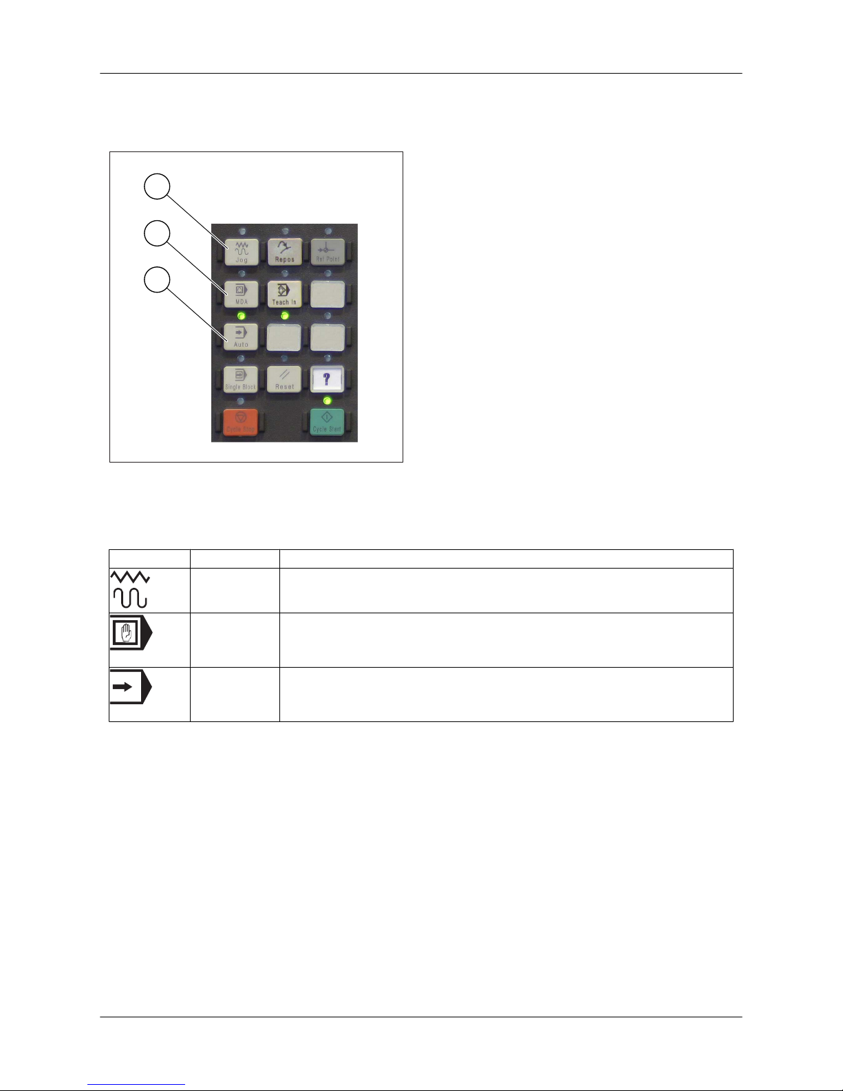
6.8. Operating modes
Operating modes are JOG, MDA, and AUTO. Only one mode can be active at a time. The mode is
selected from the control panel. The selected mode is indicated by a signal light above the button.
2
3
1
1. JOG - manual mode
2. MDA - program run block by block
3. AUTO - automatic mode
Symbol Function Description
JOG Manual operation
Machine axes are operated manually.
MDA Manual Data Automatic
The machine is controlled by running the program a block or a sequence
of blocks at a time.
AUTO Automatic operation
The machine executes the commands of the active NC program automatically.
6.8.1. JOG mode
JOG mode is used when
• setting up the machine
• changing tools
• operating X and Y axes in manual mode
User Guide - E5 Turret Punch Press
31 (46)
Page 32
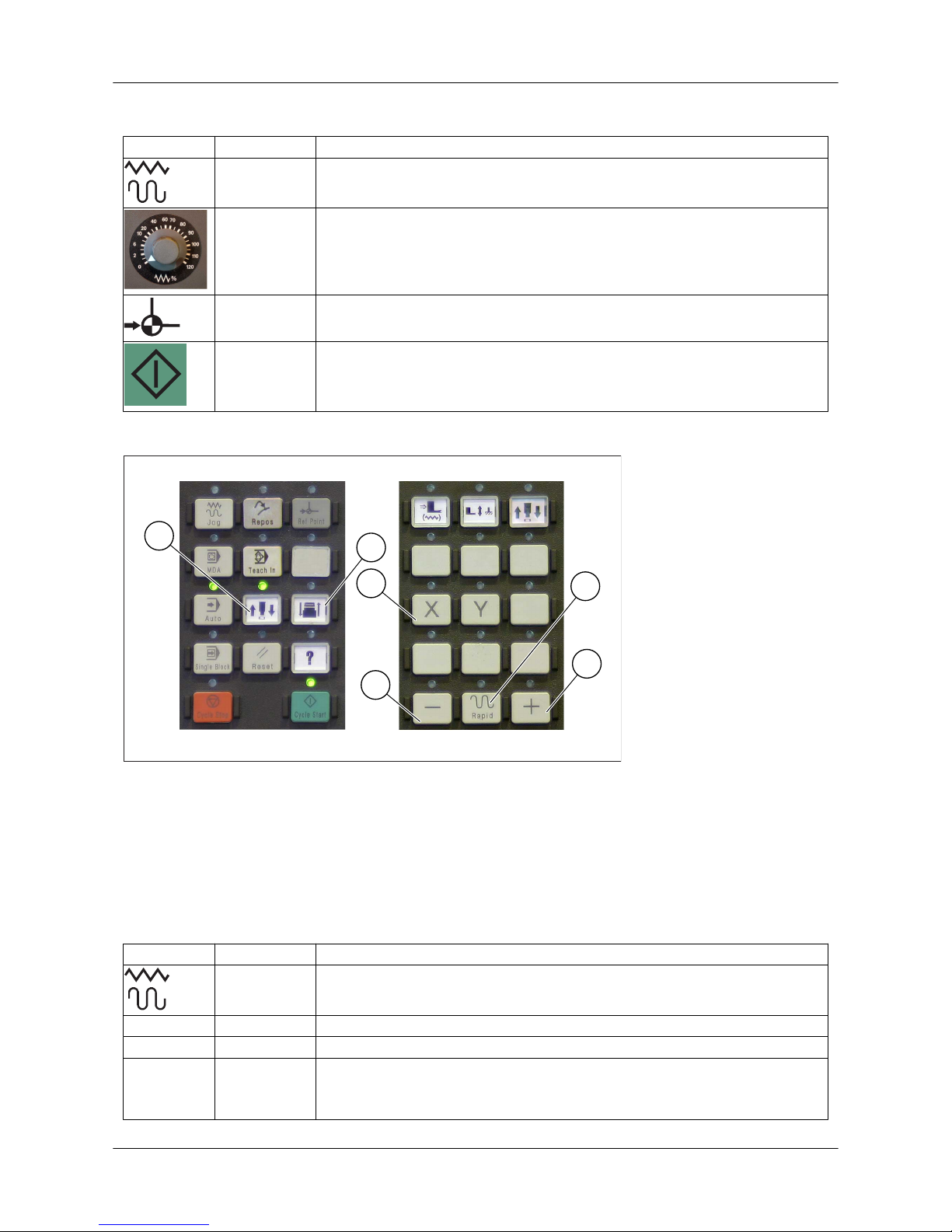
Referencing
Symbol Function Description
JOG Select manual mode.
FEED RATE Select a feed rate value > 0%.
REF Select referencing.
CYCLE
START
Start referencing. Wait until referencing is completed. Each axis reaching
the reference point is seen on the machine display.
Manual operation
2
6
5
1
3
4
Figure: Axis selection
1. Selection of upper ram (RAM axis)
2. Selection of lower ram (FORM axis, option)
3. Axis selection (X/Y)
4. Direction button in the minus direction
5. Direction button in the plus direction
6. Rapid movement (Rapid)
Symbol Function Description
JOG Select manual mode.
X/Y AXIS Select axis.
+/- DIRECTION Select direction.
Rapid MOVEMENT Rapid movement
Axis movement in manual mode speeds up when the Rapid button and
a direction button are pressed at the same time.
User Guide - E5 Turret Punch Press
32 (46)
Page 33
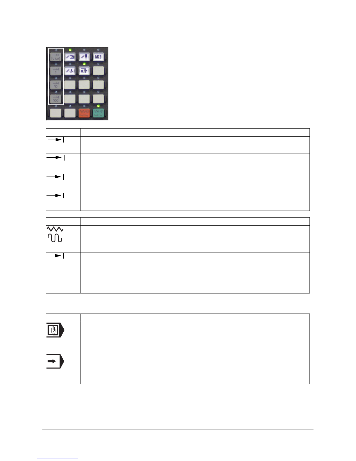
Incremental movement
Symbol Description
[VAR]
Freely definable incremental movement
1
Incremental step 0.001 mm
10
Incremental step 0.010 mm
100
Incremental step 0.100 mm
Symbol Function Description
JOG Select manual mode.
X/Y AXIS Select axis.
10
MOVEMENT Select incremental movement (VAR/1/10/100).
+/- DIRECTION Select direction (+/-).
• When you press the direction button, the axis moves by the selected
step.
6.8.2. MDA and AUTOMATIC modes
Symbol Function Description
MDA Manual Data Automatic
• The machine is controlled by running the program a block or a sequence of blocks at a time.
• Start by pressing the CYCLE START button.
AUTO Automatic operation
• The machine executes the commands of the active NC program automatically.
• Start by pressing the CYCLE START button.
6.8.3. Feed rate control
• Note: The feed rate is limited to 20% until referencing is completed.
• The reading of the feed rate switch stands for percentage of the programmed F value.
User Guide - E5 Turret Punch Press
33 (46)
Page 34
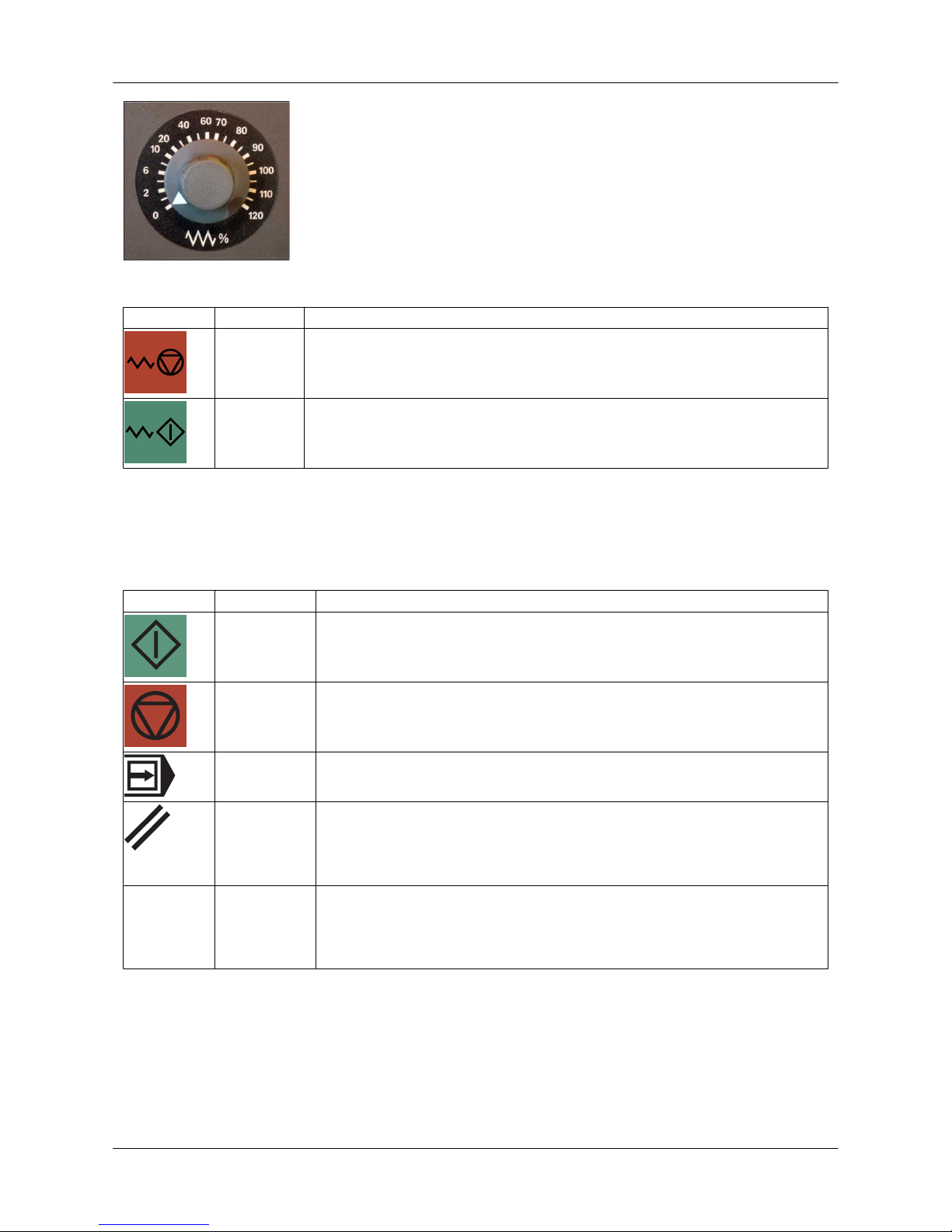
Figure: Feed rate switch
Symbol Function Description
Feed stop Feed stop
• Axes stop in a controlled way.
Feed start Feed start
• Axis movements can continue from the stopping point.
6.8.4. Program control buttons and function keys
• The selected function is indicated by a signal light above the button when the button is pressed.
• In some functions, the first keystroke starts the function (the signal light goes on), and the
second keystroke stops it (the signal light goes out).
Symbol Function Description
CYCLE
START
The selected program starts from the beginning or from the interruption
point.
CYCLE
STOP
Running of the selected program is interrupted.
• The axes stop at the end of the current block.
Block by
block
The program is run block by block.
RESET button
This stops the program run.
• Alarms on the display are cleared (except for the POWER ON and
RECALL alarms).
• The control shifts to RESET status.
M26
Stroke with
dwell
Dwell time between axis positioning and punching stroke
• The stroke with dwell is active the whole time this button is active.
• During the dwell time, mechanical vibration has damping time, which
improves punching accuracy.
User Guide - E5 Turret Punch Press
34 (46)
Page 35
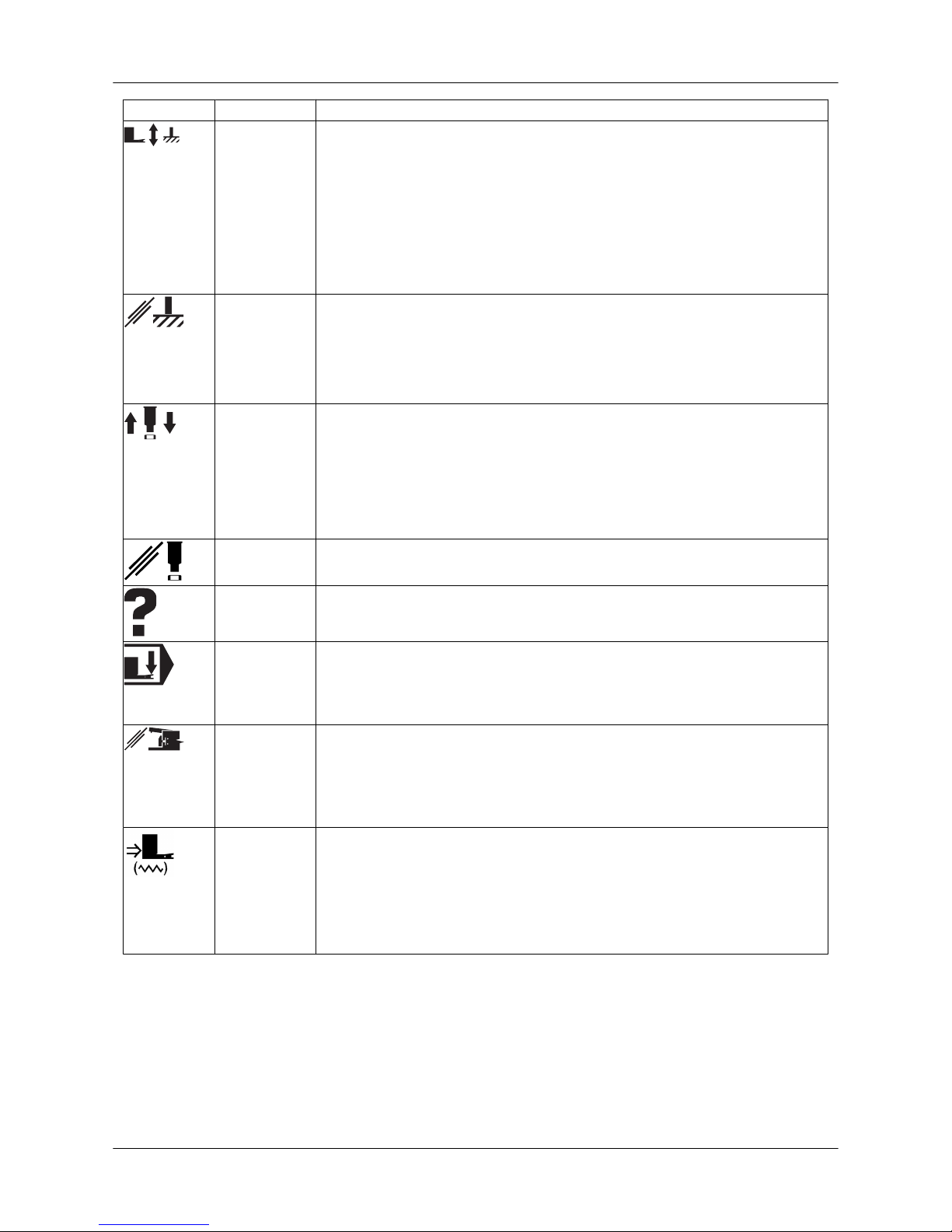
Symbol Function Description
Clamps, Xpin and
sheet support rollers
Clamps and X-pin
• The clamps open and the selected X-pin (1-4) rises.
• When the clamps are open, all axis movements are disabled.
• When you press the button again, the clamps close and the X-pin retracts.
• The function can be activated by the CLAMPS command in all modes.
• The sheet support rollers rise when the X-pin is up and the clamps are
open.
X-pin disabled
When the X-pin is disabled, the clamp opening button and the foot pedal
operate as follows:
• First keystroke: clamps open
• Second keystroke: X-pin rises
• Third keystroke: clamps close, X-pin moves down
Punching Punching stroke
• Single punching stroke
• In SG machines, a single shearing stroke is also possible.
• The function is operational only in JOG mode when the hydraulic system is on.
(NOT in E machines)
Punching disabled
Program run without punching strokes and right angle shearing.
Alarm reset
button
Alarm reset
• Alarms can also be reset via the RESET button.
Automatic
clamping
Automatic clamping
• The clamps close automatically when the sheet is pushed between the
clamps and the sheet detectors are activated.
• As soon as the clamps close, the X-pin retracts.
Sheet detection bypass
Bypass of sheet detectors
• This function is used for testing programs without a sheet and when
the sheet has come off the clamps.
• When sheet detection is activated, X- and Y-axis movements are possible only if all sheet detectors are activated.
Clamp setting
Opening of the clamps' central locking
• The clamps are unlocked and can be moved to the desired position
on the X slide guide.
• When you press the button again, the clamps are re-locked on the
guide.
• The function is operational only in JOG mode.
User Guide - E5 Turret Punch Press
35 (46)
Page 36
7. Preventive maintenance
Ensure reliable and trouble-free operation of the machine by carrying out the preventive maintenance
operations according to the instructions delivered with the machine and by paying attention to the
machine's functions continuously. Perform the preventive maintenance as the schedule given indicates. Reset the maintenance intervals in the Tulus software's Equipment status / Maintenance field.
• Weekly and monthly maintenance operations can be performed by the end user.
• Six-month maintenance is to be performed by authorised Finn-Power service personnel only.
• The person responsible for machine maintenance must document all maintenance and servicing in the maintenance diary delivered with the machine.
• The warranty is valid only if maintenance has been carried out according to the instructions and
documented in the maintenance diary.
WARNING
It is strictly forbidden to operate a machine that is out of order.
NOTICE
• Use a hand-operated grease gun when you add grease through
the grease nipples.
• Repair all faults and defects detected during the checks.
• Never use compressed air for cleaning.
• If you have any problems, feel free to contact Finn-Power's service department.
User Guide - E5 Turret Punch Press
36 (46)
Page 37
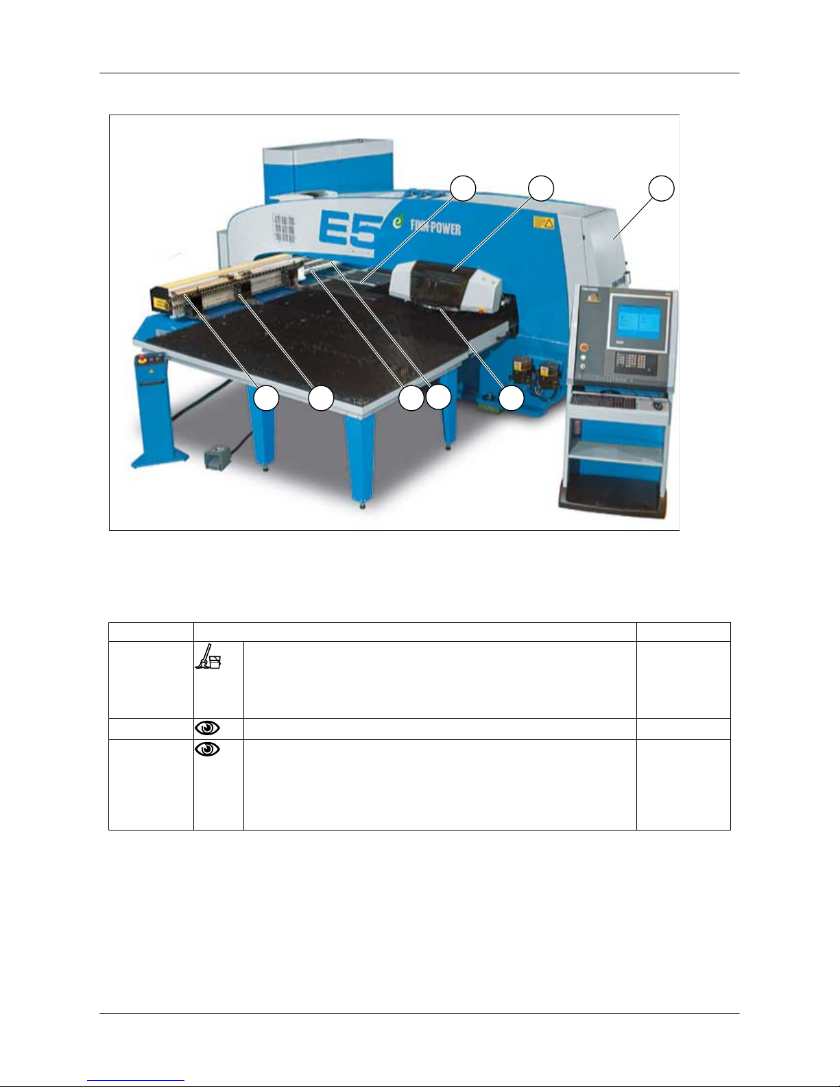
7.1. E5 maintenance points
5
2434
16
6
Figure: E5 maintenance points
7.2. E5/E6/E8 weekly maintenance
Point E5/E6/E8 Lubrication
• Clean the brush tables with a vacuum cleaner.
• Clean the X and Y linear guides.
• Clean the impurities from around the X and Y linear guides
and ball screws.
Check the compressed air feed pressure.
Check the functioning of the drain valve in the service unit’s
water separator.
• Clean the valve and filter bowl if necessary.
• The water separator is equipped with an automatic draining
system.
User Guide - E5 Turret Punch Press
37 (46)
Page 38
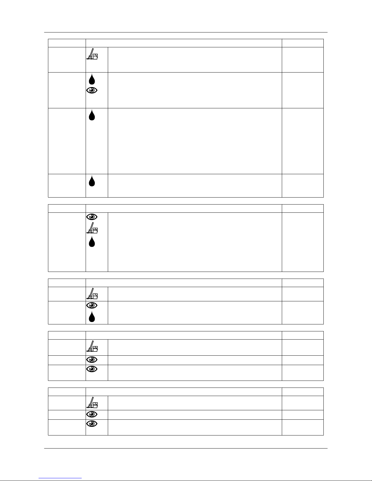
Point Turret Lubrication
1 • Clean the turret and the tool holders.
• Clean the impurities from the lower turret and the lower
frame.
1 • Lubricate the tool holders and their lifting pins.
• Check the functioning of the spring housings. Check that:
• The spring housings can be depressed by hand
• The lifting pins can raise the spring housings
A / B
1 Lubricate the index tool holders and Multi-Tool stations through
the grease nipples.
• Unlock the lower holders by pushing the locking pin upward
with, for example, a screwdriver.
• Rotate the upper and lower holders at intervals of 90 degrees.
• Lubricate for each angle.
• Rotate the upper and lower tool holder to zero angle.
F / Nipples
according to
delivery
2 (option) Lubricate lower forming holders Bif, Cif, and Dif by adding some
lubricant.
F / Nipples
according to
delivery
Point Tools Lubrication
1 (option) Check the tightness of the flat-head screw in the Multi-Tool.
Unscrew the screw only when the ejector spring is changed. If
the screw is unscrewed or if it has loosened:
• Clean the grease off the tapping with a solvent
• Use Loctite 242 or similar for locking
• Apply a tightening torque of 42 Nm
Clean and lubricate the punch cartridge of the Multi-Tool.
A
Point Tapping unit TU6 Lubrication
(option) Clean the tapping unit and the spill tray.
(option) Check the amount of oil in the tapping unit lubricator. D
Point Punching mechanism (ONLY E-series machines) Lubrication
Clean the roll surface and guiding surface in the punching
mechanism.
Check the functioning of the punching motor coolers.
Check the condition of the hoses in the cooling system and the
tightness of the joints.
Point Scrap conveyors Lubrication
(option) Clean the scrap conveyors.
(option) Check the tension, condition, and alignment of the belts.
(option) In conjunction with vacuum system maintenance:
• Check the vacuum system filter and clean it if necessary.
User Guide - E5 Turret Punch Press
38 (46)
Page 39
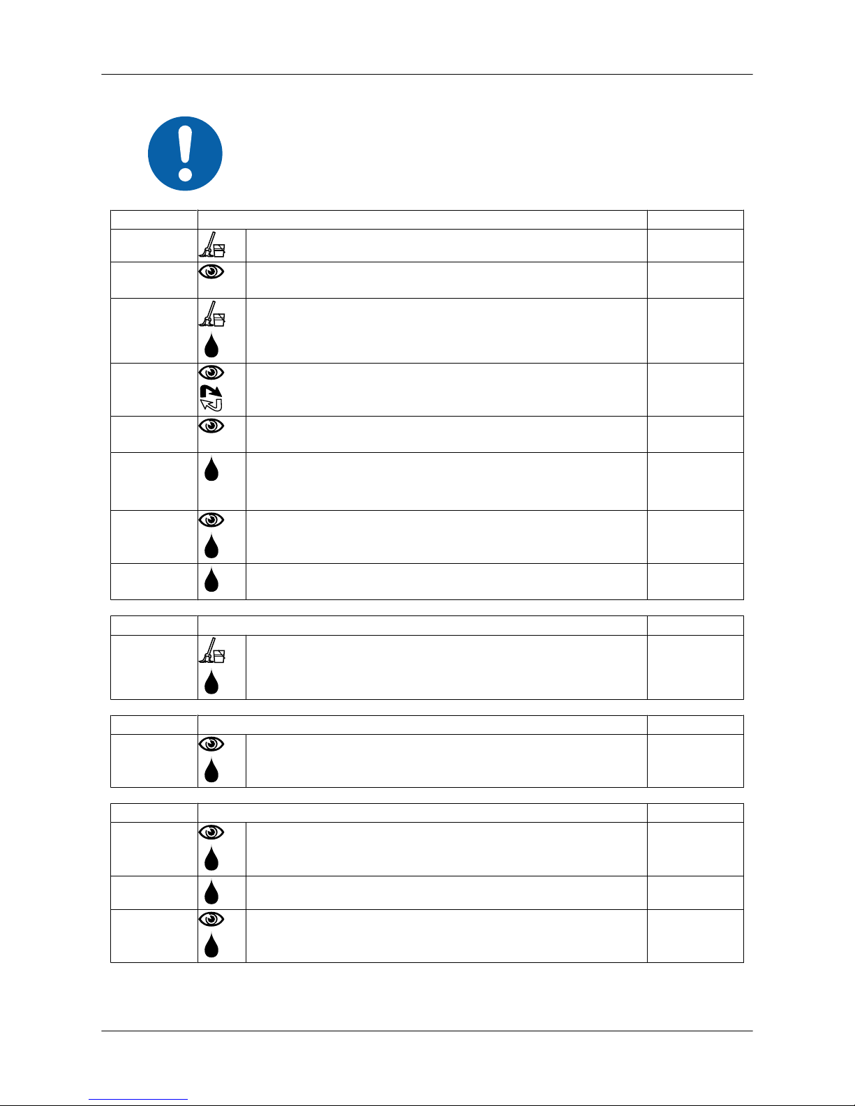
7.3. E5/E6/E8 monthly maintenance
Perform the weekly maintenance listed also each time the
monthly maintenance is performed.
Point E5/E6/E8 Lubrication
Clean the air cooler condenser in the control centre.
Check the condition of the energy transfer chains of the
coordinate table.
3 Clean and thinly lubricate the flat guide of the clamps. A
Check the condition of the clamp pins. Replace if necessary.
Check the condition and tightness of the compressed air supply
hoses coming to the clamps.
4 Lubricate the slides of the X and Y linear guides.
• E6/E8: X-nipples (10 pcs), Y-nipples (4 pcs)
• E5/C5: X-nipples (8 pcs), Y-nipples (4 pcs)
C
5 Check the lubricant level in the central lubricating device (NOT
C5/E5).
C
6 Lubricate the ball screws and thrust bearings of the X and Y
axes (ONLY C5/E5).
C
Point Turret Lubrication
1 Clean and lubricate the turret conical sleeves. A
Point Punching mechanism (E-series machines) Lubrication
5 Check the lubricant level in the lubricating device of the toothed
bar of the punching mechanism.
C
Point Tools Lubrication
5 (option) Check the oil level and functioning of the tool lubricator. A
(option) Lubricate the locking pin of the tapping unit. C
(option) Check the oil level in the tapping unit turret through the sight
glass in the turret side. The oil tank volume is 0.3 litres.
E
User Guide - E5 Turret Punch Press
39 (46)
Page 40
Point Sheet lubricator Lubrication
(option) Check:
• The functioning of the sheet lubricator
• The suction filter and nozzle of the sheet lubrication tank
Clean when necessary.
7.4. Compact Express, monthly maintenance / LD, monthly maintenance
Point Compact Express / LD Lubrication
Check the compressed air feed pressure.
Check the functioning of the drain valve in the service unit’s
water separator.
Check the condition and functioning of the sheet support rollers,
sheet detectors, and positioning pins of the brush table.
Check the condition and functioning of the suction cups and
ejectors.
Check the condition and tightness of the pneumatic tubing.
Check that the tubes do not chafe against anything.
Check the tension and condition of the cogged belt of the
horizontal movement.
7.5. Recommended lubricants
NOTICE
• The worm gears of the tool rotation system are lifetime-lubricated with synthetic gear oil.
• If you have to replenish the oil, always use an oil corresponding
to the gear oil (E).
Oil/grease/fluid Specification Example
A Lubricating oil ISO VG 46
DIN 51524: HL or HLP
ISO 6743/4: HM or HV
Oil purity requirement: ISO
4406/1999: 16/14/11 or
NAS 1638: NAS 5
• Neste Paine 46 (Finn-Power primary assembly oil)
• Avia Avilub RSL 46
• Avia Avilub HVI 46
• BP Energol HLP 46
• BP Bartran HV 46
• Esso Nuto H 46
• Esso Univis N46
• Mobil DTE 25
• Mobil DTE 15
• Mobil DTE EXEL 46 (without zinc)
B Gear wheel grease NLGI 2 • BP Energrease L21-M
• Shell Kuggfett
• Esso Beacon EP2
• Mobil Mobilgrease Special
• Teboil Multi-Purpose
• Neste Molygrease
User Guide - E5 Turret Punch Press
40 (46)
Page 41

Oil/grease/fluid Specification Example
C Bearing grease NLGI 2 • Shell Alvania RL2
E Gear oil ISO VG 460-680 • Shell Tivela Oil S 460
F Petroleum jelly Multipurpose EP 00
NLGI grade 00
• Petro-Canada Multipurpose EP 00
G Gear oil Mineral oil ISO VG 220 • BP Energol GR-XP 220
• Castrol Alpha SP 220 or Hypoy EP 90
• Esso Spartan EP 220 or GP 90
• Mobil Mobilgear 630 or Mobilube GX 85
W-90-A
• Shell Omala Oil 220
H Ball screw grease (E
and V axis)
Grease based on lithium
soap thickener
• base oil viscosity 130
cSt / +40 °C, mineral oil
as base oil
• standard operating
temperature range: -10
to +110 °C
D Cutting fluid 20% • ISOCOOL 990
• Ecocool 206
G Radiator fluid 40% • BS 6580/92 Neste Super radiator fluid XLC
User Guide - E5 Turret Punch Press
41 (46)
Page 42

8. Multi-Tool tool station (option)
The fixed Multi-Tool stations are installed in the 135 mm turret holes.
The drop-in Multi-Tools are installed in the Di tool stations.
Multi-Tool tool stations MT6-A/135, MT8i-16, MT20i-8, MT8Ri, and MT3Ri are manufactured by Wil-
son Tool International, whereas the MT24-8, MT8-24, MT10-16, MT6-AU, MT-8AUi, and MT-3BUi
are manufactured by MATE Precision Tooling.
Tool station Number of tools
MT24-8 24 pcs, max. diameter 8 mm
MT8-24 8 pcs, max. diameter 24 mm
MT10-16 10 pcs, max. diameter 16 mm
MT6-A/135 6 Thick Turret (AM) tools, max. diameter 12.7 mm
MT6-AU 6 Thick Turret (AM) tools, max. diameter 12.7 mm
MT8i-16 (drop-in
Multi-Tool)
8 Thick Turret (AM) tools, max. diameter 16 mm (fixed angle)
MT20i-8 (drop-in
Multi-Tool)
20 Thick Turret (AM) tools, max. diameter 8 mm (fixed angle)
MT-8AUi (drop-in
Multi-Tool)
8 pcs, max. diameter 12.7 mm (fixed angle, Ultra TEC 1/2" punches of size A)
MT-3BUi (drop-in
Multi-Tool)
3 pcs, max. diameter 31.75 mm (fixed angle, Ultra TEC 1 1/4" punches of size
B)
MT8Ri (drop-in
Multi-Tool)
8 pcs, max. diameter 16 mm (indexable)
MT3Ri (drop-in
Multi-Tool)
3 pcs, max diameter 31.75 mm (indexable, HP Thick Turret punches of size B)
User Guide - E5 Turret Punch Press
42 (46)
Page 43

9. Additional clamp (option)
All turret punch presses have connectors for the installation of an additional clamp. To install the
additional clamp, connect the pneumatic coupling and push the clamp into its place on the guide. The
central locking of the clamps must be open for attachment of the clamp to the guide.
• Remove coupling 1_3J153.3 when installing the third clamp in
its place. Attach coupling 1_3J153.3 when removing the third
clamp.
• Remove coupling 1_3J153.4 when installing the fourth clamp in
its place. Attach coupling 1_3J153.4 when removing the fourth
clamp.
User Guide - E5 Turret Punch Press
43 (46)
Page 44
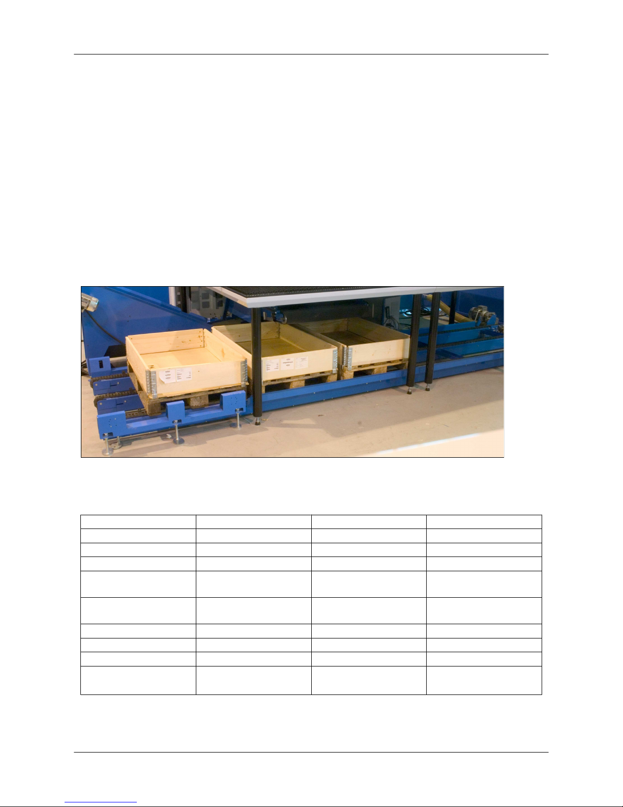
10. SU3/SU6C/SU9 sorting unit (option)
The SU sorting unit is equipped with an inverter-controlled squirrel-cage induction motor, moving
EUR pallets on three chains. There are three types of sorting units, the SU3, SU6C, and SU9. All
types can accommodate three EUR pallets, but the number of sorting addresses varies. It is recommended to use pallets with collars in the sorting unit.
• The SU3 sorting unit is used to sort workpieces coming from the work chute, sending them to
three different sorting addresses. The maximum part size fitting on a pallet is X1200 x Y800.
The maximum size of a part leaving the work chute is X500 x Y500.
• The SU6C sorting unit is used to sort parts cut by the SG right angle shear to six different
addresses. The pallets on the chain are divided into two sections; accordingly, the maximum
part size is X1200 x Y400.
• The SU9 sorting unit is used to sort parts coming from the LP6- and LPe6-machine's small and
big work chute, sending them to a maximum of nine different sorting addresses. Each pallet
has been divided into three sections: two small sections (400 x 400) and one big section (800
x 800).
Figure: 4993 SU sorting unit
10.1. Technical data SU3/SU6C/SU9
SU3 SU6C SU9
Sorting addresses 3 6 9
Address change time 2 to 6 s 2 to 6 s 2 to 6 s
Nominal speed (50 Hz) 250 mm/s 250 mm/s 250 mm/s
Max. size of a pallet
(box) (X x Y)
1200 mm x 800 mm 800 mm x 1200 mm 1200 mm x 800 mm
Max. height of a pallet
(box) with collars
350 mm 350 mm 350 mm
Motor 1.5 kW / 400 V / 50 Hz 1.5 kW / 400 V / 50 Hz 1.5 kW / 400 V / 50 Hz
Max. load 3000 kg (1000 kg / pallet)3000 kg (1000 kg / pallet) 3000 kg (1000 kg / pallet)
Width 1230 mm 1230 mm 1230 mm
Length SU3: 5554 mm
SU3L: 6714 mm
7642 mm SU9: 5554 mm
SU9L: 6714 mm
User Guide - E5 Turret Punch Press
44 (46)
Page 45
Weight SU3: 680 kg
SU3L: 780 kg
630 kg SU9: 680 kg
SU9L: 780 kg
Length of movement SU3: 4140 mm
SU3L: 5300 mm
7224 mm SU9: 4140 mm
SU9L: 5300 mm
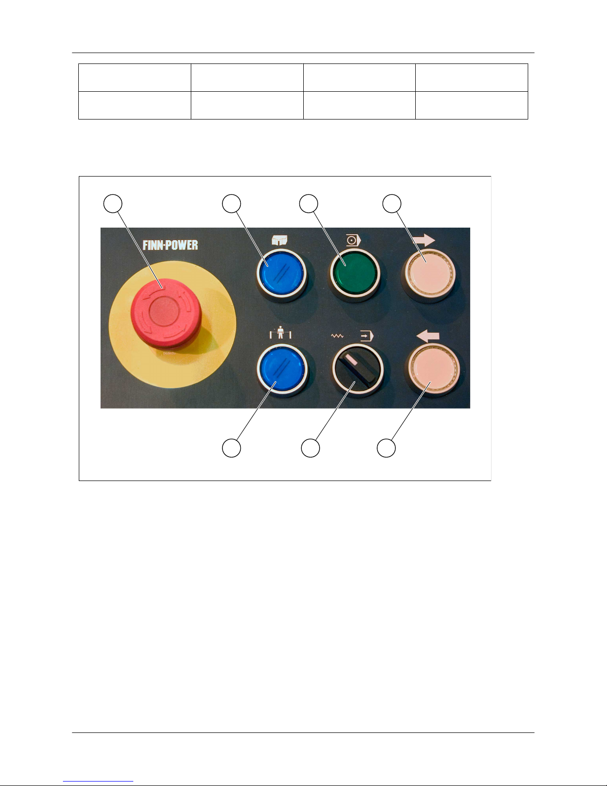
10.2. Control panel
Regardless of the machine's safety systems, the control panel of the SU is always similar. Any buttons
related to safety systems not installed on the SU have no function.
1
2 3
4
5
6
4
Figure: 4982 SU control panel
1. Emergency stop button
2. SU safety door reset button
3. Automatic mode starting button + SU mode
indicator light
4. Chain manual operation buttons
5. SU safety circuit reset button
6. Manual/automatic mode selector switch
10.2.1. Manual mode
Select the manual mode with the manual/automatic mode selector switch on the SU control panel.
In manual mode, you can operate the chain in either direction by using the chain manual operation
buttons.
User Guide - E5 Turret Punch Press
45 (46)
Page 46

Setting a pallet on the chain
• Select manual mode from the SU control panel.
• Using the chain manual operation buttons, run the desired SU chain loading stoppers to the
loading location.
• Set the pallet on the chain between the loading stoppers.
Removing a pallet from the chain
• Select manual mode from the SU control panel.
• Using the chain manual operation buttons, run the desired pallet to the loading/unloading location.
• Remove the pallet from the chain.
10.2.2. Automatic mode
• Lock the SU safety door (optional).
• Reset the SU safety circuits.
• Turn the manual/automatic mode selector switch to the automatic mode position.
• With the indicator light on the automatic mode starting button blinking, push the automatic mode
starting button.
• As the SU switches over to automatic mode, the indicator light on the automatic mode starting
button is lit continuously and the SU chain is positioned at the last address requested by the
program.
10.3. Sorting unit addresses
In automatic mode, the pallets move to the correct addresses on the basis of the sorting address
specified in the NC program. When the sorting unit is used, use the PRESORTING and SORTING
subroutines.
• The sorting addresses of the SU3 range from 37 to 39.
• The sorting addresses of the SU6C range from 31 to 36.
• The sorting addresses of the SU9 range from 31 to 39.
User Guide - E5 Turret Punch Press
46 (46)
Page 47

User Guide - E5 Turret Punch Press
47 (46)
Page 48

A Company of PRIMA INDUSTRIE Group
FINN-POWER Oy P.O. Box 38 62201, Kauhava, FINLAND
Tel. +358 6 428 2111 Fax + 358 6 421 2244
www.finn-power.com
 Loading...