

Page 1
MONO
PLUS 2
CHASSIS (MP2)
TV
10/1998
@ Service
@ Service-Manual
®
Serviceanvisning
manual
AKAI
TV
1420-UK
TV
1420-T UK
TV
1420-Euro
TV
1420-T Euro
TV
1421
TV
1421-T
TV
1421-T Euro
TV 2020 UK
TV
2020-T UK
TV 2020-Euro
TV
2021
TV
2021-T
TV
2021-T Euro
TV
2120-T UK
TV
2120-Euro
TV
2120-1 Euro
TV
2121
TV
2121-T
TV
2121-T Euro
®
CD
FINWX
14A1 TX
51A1 TX
55A1 TX
LUXDR.
3392
TX
5192
TX
5592
TX
SALORA
14MP50 VT TICO
20MP50 VT TICO
21MP50 VT TICO
Manuel
Manuale
de service
di
servizio
NOKIA
3721
3721-T Euro
5121
5121-1
5121-1 Euro
5521
5521-T
5521-1 Euro
o
''''.
CLE-:::Ti:l0t~IC
www.microelectronic.co.yu
Page 2
GE3
0
Service adjustmmts
Note! Before other adjustments Ul voltage must be adjusted.
If the set cannot be switched on with the number buttons, please see
under “RC Mode” (Service menu 2).
Wait! Allow the TV set to be switched on for 10 minutes before any
adjustment.
Service mode
Select the service mode by pressing the Mute, OK (MI and TV buttons in
sequence on the remote control unit. Use the blue button to call up the
Service Menu 2, 3 (or Service Menu 1 again).
Cursor button A or v
Cursor button 4 or)
OK (M) button
TV button
= To select required adjustment
= To adjust it
= To store the adjustment into the memory.
= To return to normal TV mode.
Service adjustments which are made in service mode
Display
Start APS
V-Amplitude
H-Shift
Ul
AGC
Set Standard
APS Standard
RC Mode
Front AV
Text Characters
Equalizer
C4 Bit
Loudness
AVC
Carrier Mute
Hi-Dev
Note
Service Menu 1
YES = APS; search function will be run automatically
when the set is switched on for the first time and stores
all stations into the memory.
Adjust the bottom edge.
Stereo set: Adjust centre of the test picture horizontaly
to a centered position.
Mono set: Adjust centre of the test horizontal to a
centered position with RK 45.
Ul operating voltage, see adj. “Ul voltage”.
See adjustment “AGC”.
Service Menu 2
Select required standard.
Set to approriate television standard.
(Remote Control), select the other remote control units.
YES, if front AV socket is available.
Teletext character sets: OFF, EUtCS, EUtTR,
East 1, East 2
Service Menu 3 (only with stereo sets)
YES/NO ; YES = on
Ya$witches back to FM-sound, if FM-sound # Nicam
No: Switches Nicam during Nicam-transmission.
YES/NO
Yes: Supresses sound cracks.
Yes: Switches sound off, if carrier missing.
Displays “HDM” line in the audio menu, use
in case of overmodulation of sound.
Adjustment Ul voltage
1. Set the contrast and brightness to minimum.
2. Connect test point XFOI (chassis board) to ground.
3. Go to service menu 1 (see service mode).
4. Use cursor button A or v to select Ul-adjustment.
5. Adjust with cursor button 4 or)
IlOV f IV 14” (Philips/Samtel ) and 20” (Videocolor)
135V i IV 21” (Philips)
150V + IV 25” and 28” (Videocolor)
6. Use OK (M) memory button to store the value into the memory.
7. Remove XFOl/ground connection.
8. Return to normal TV mode by pressing the TV button.
AGC
1. Connect test point XFOl (Chassis board) to ground.
2. Feed in RF signal without sound carrier with 72 dBpV (= 4mV) on a
medium UHF channel via the aerial input.
3. Go to service menu 1 (see service mode).
4. Use cursor button A or v to select AGC adjustment.
5. Connect oscilloscope (Bandwidth > 50 MHz) to the tuner’s IF output
(test point XL03 or XLO4) and to ground (XLO2).
6. Use cursor button 4 and) to adjust 350 mVpp +O/-50mV with
reference to the signal’s synchronizing peaks.
7. Use OK (M) memory button to store the value into the memory.
8. Remove XFOl/ground connection.
9. Return to normal TV mode by pressing the TV button.
Other service adjustments
Horizontal amplitude
Adjust 90” CRTs horizontal amplitude with coil LK 12.
Adjust 110” SQ and FST - CRT’s with resistor RK66.
Vertical position
Adjust vertical position by severing resistor RS24, and/or RS14.
Focus
Use focus adjuster TK02 (at horizontal transformer) to set the focus to
optimum sharpness.
Cushion
Adjust 110” SQ and FST CRT’s with resistor RK60.
G2 and colour temperature
1. Set the UG2 adjustment (the lower adjustment at horizontal
transformer) to its middle position.
2. Select the IDEAL picture setting and switch the set to AV programme
number or other black screen picture.
3. Using the oscilloscope with 1OO:l probe determine the colour cathode
with the highest black level measuring pulse at IC NHOl,
pins 9, 12 and 15.
4. Adjust the highest measuring pulse to 150V (measured against ground).
AFC
1. Feed in symmetric IF signal (ca. 0,8 Vpp) by means of 4:l transmitter at
test points XL 03 and XL 04. (38,9 MHz for standard BG, DK and 39,5
MHz for standard I)
2. At test point XL 01 (XL 02 to ground) set 3,5 V DC i 0,5 V with coil ZL 01
(AFC reference).
3. Multistandard set, standard L’: After proper BG adjustment select a
channel in band 1 (L’-range). Activate standard L in Tuning menu.
Feed in symmetric IF signal (ca. 0,8 Vpp) by means of 4:l transmitter at
test points XL 03 and XL 04. (33,9 MHz for standard L’) At test point XL
01 (XL 02 to ground) set 3,5 V DC + 0,5 V with capacitor CL 05.
AFC check
Detune the IF signal to approx. 39 MHz (39,7 MHz, 34 MHz). Then the
voltage must drop to approx. IV.
Sound of multistandard sets
(standard BG, DK or standard I)
Make the standard adjustment as follows:
1. RCF remote control unit: Press the PROG button.
RCN remote control unit: Press the blue MENU button twice.
2. Select the menu line Tuning, Manual tuning.
3. Select STANDARD BG, DK or I with cursor buttons 4 and ).
4. Store the setting by pressing the OK (M) button.
5. Return to normal TV viewing by pressing the TV button.
AM sound (multistandard module)
1. Connect a sweep generator with 30-40 MHz marking to pin 14 of AL-
connector.
2. Connect an oscilloscope to pin 11 of AL-connector.
3. Connect a control voltage supply to pin 3 of TDA 9830.
4. L standard: The voltage at pin 09 of AL-connector = 0 V.
Set the output amplitude to 200 mV by means of the control voltage and
keep this value during the adjustment.
Adjust the amplitude of 34,2 MHz to maximum with ZL 651 and ZL 652.
5. After proper L-adjustment:
L’ standard: The voltage at pin 10 of AL-connector = 12 V.
Set the output amplitude to 200 mV by means of the control voltage and
keep this value during the adjustment.
Adjust the amplitude of 40,4 MHz to maximum with RL 673.
Page 3
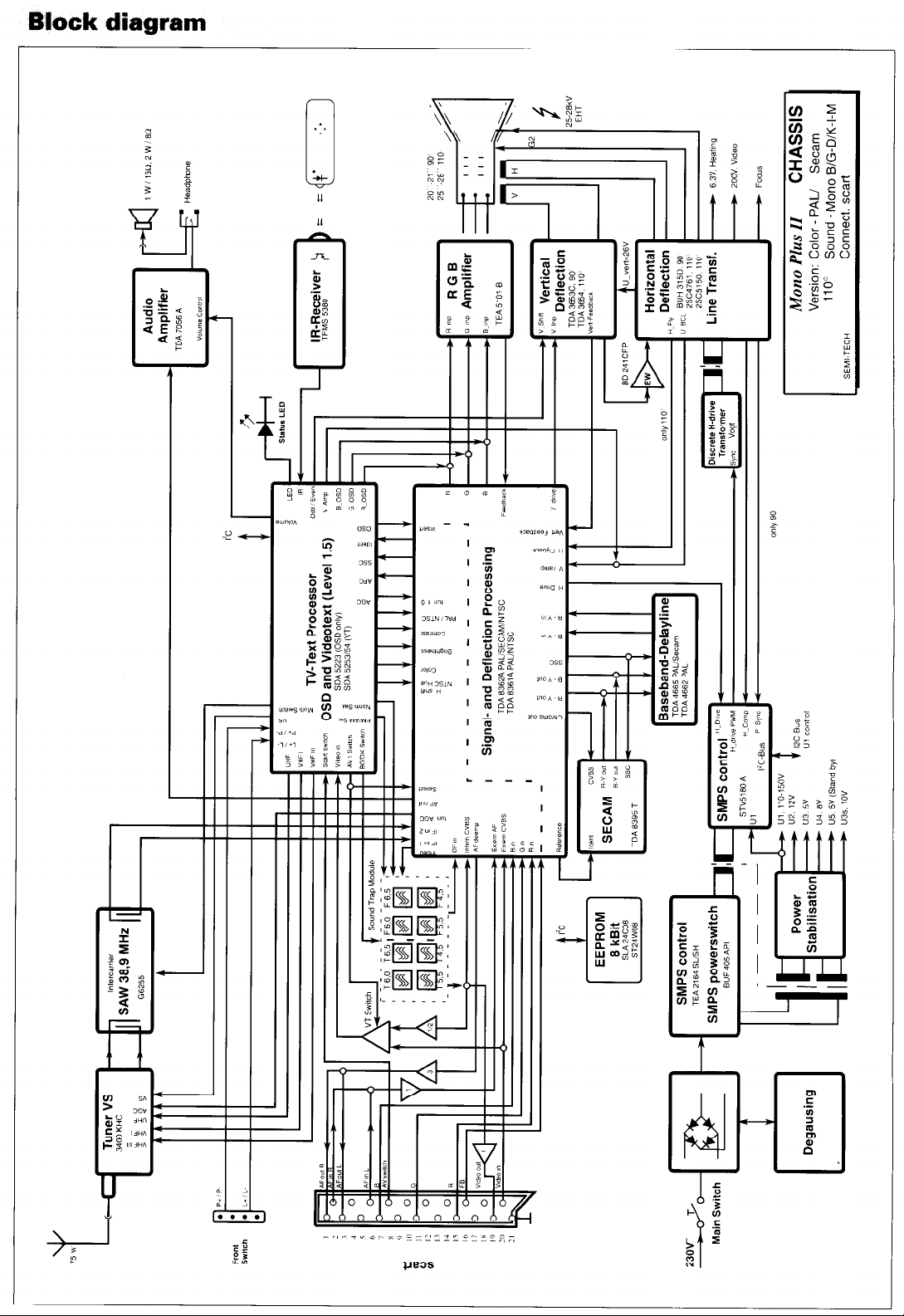
Block diagram
cl-n
.
-
I
---
-I
-
-
t
-
-
-
-
Al
I
F
‘Z
:
F
P
Y
-
Page 4

AtUl-Module 5825 20 25
r
T
‘I-.
7KL
I
I
T
Page 5

Ino
GW
L
l-,20’
- .c
NETZVERBUNDENIMAINS-CONNECTEDICOLLEGATO ALLA RETE’ NETZGETRENNTIMAINS-INSULATED/SEPARATO DALLA RETE
,__________.._______-.._________--
-----._.____.___.___..-_.___..__.-----------------.__.
Page 6

YI
___________-_--_________________________-----______--________-~________._____________ ___
r
TUNER
r
L___..________._________..__
“lx?
s
c~mr~rrr,s,rrrur*:______________.._.‘_____....__________._________________________‘____-...._.._......____._...
DEGIUISIW Wll.
8001NI 5nlGNET1.?ZIZIOWE
A
NETZVEREUNDEN/MAINS-CONNECTEDICOLLEGATO
L$ Ino
NETZCETRENNT/~~AINS-INSUL
Page 7

VERT.ABLENKUNG
VERT.DEFLECTION
mii I ’ 1 T \’
NETZGETRENNTIMAINS-INSULATEDISEPARATO DALLA RETE
; ____... _..._ ___________...._._______.__.... _____ _________.... __._.._.._.....__._.._._.““...““”.~~~.”1”’p”.~..““~.....cHD~T.__ _.... ____
Page 8

SIGNAL-PROCESSOR
PROCESSORE SEGNAL
._. ,
20- MO”
1.~tM,21- 360”
Page 9

Ilk/ r
____-_-_- ____-----__
Nwsw .I55 4034’
l9lIsN .,Sl 0007’
h I I
0001
Operotlng-lJn1t
Processor-Synbo I
x*01
C-
zoo” ’ c:-:
<b-r
(S-2
 Loading...