

finjan Vital Security NG-8000, Vital Security NG-6000, Vital Security NG-5000 Setup And Configuration Manual

Software Release 9.0
NG-8000
NG-5000
NG-6000
Setup and
Conguration Guide

Setup and Configuration Guide
Vital Security™ Appliance Series NG-5000/NG-6000/NG-8000 Setup and Configuration Guide
© Copyright 1996 - 2008. Finjan Software Inc. and its affiliates and subsidiaries (“Finjan”). All rights
reserved.
All text and figures included in this publication are the exclusive property of Finjan and are for your
personal and non-commercial use. You may not modify, copy, distribute, transmit, display, perform,
reproduce, publish, license, create derivative work s from, transfer, use or sell an y part of its content
in any way without the express permission in writing from Finjan. Information in this document is
subject to change without notice and does not present a commitment or representation on the part
of Finjan.
The Finjan technology and/or products and/or software described and/or referen ced to in this
material are protected by registered and/or pending patents including U.S. Patents No. 3952315,
6092194, 6154844, 6167520, 6480962, 62091 03, 6298446, 6353892, 6804780, 69 22693,
6944822, 6993662, 6965968, 7058822, 7076469, 7155743, 7155744 and may be protected by
other U.S. Patents, foreign patents, or pending applications.
Finjan, Finjan logo, Vital Security, Vulnerability Anti.dote and Window-of-Vulnerability are
trademarks or registered trademarks of Finjan. Sophos is a registered trademark of Sophos plc.
McAfee is a registered trademark of McAfee Inc. Kaspersky is a registered trade mar k of Ka spersky
Lab. Websense® is a registered trademark of Websense, Inc. IBM® Proventia® Web Filter is a
registered trademark of IBM Corporation. Microsoft and Microsoft Office are registered trademarks
of Microsoft Corporation. All other trademarks are the trademarks of their respective owners.
For additional information, please visit www.finjan.com or contact one of our regional offices:
USA: San Jose
2025 Gateway Place Suite 180 San Jose,
CA 95110, USA
Toll Free: 1 888 FINJAN 8
Tel: +1 408 452 9700 Fax: +1 408 452 9701
salesna@finjan.com
USA: New York
Chrysler Building
405 Lexington Avenue, 35th Floor
New York, NY 10174, USA
Tel: +1 212 681 4410 Fax: +1 212 681 4411
salesna@finjan.com
Israel/Asia Pacific
Hamachshev St. 1,
New Industrial Area Netanya, Israel 42504
Tel: +972 (0)9 864 8200
Fax: +972 (0)9 865 9441
salesint@finjan.com
Europe: UK
4th Floor, Westmead House,
Westmead,
Farnborough, GU14 7LP, UK
Tel: +44 (0)1252 511118
Fax: +44 (0)1252 510888
salesuk@finjan.com
Europe: Germany
Alte Landstrasse 27, 85521
Ottobrun, Germany
Tel: +49 (0)89 673 5970
Fax: +49 (0)89 673 597 50
salesce@finjan.com
Europe: Netherlands
Printerweg 56
3821 AD° Amersfoort
Netherlands
Tel: +31 334 543 555
Fax: +31 334 543 550
salesne@finjan.com
Catalog number: SACG-9.0-01
Email:support@finjan.com
Internet:www.finjan.com

C ONTENTS
1. Introduction. . . . . . . . . . . . . . . . . . . . . . . . . . . . . . . . . . . . . . . . . . . . . . . 1
Finjan Overview . . . . . . . . . . . . . . . . . . . . . . . . . . . . . . . . . . . . . . . . . . . . . . . . . . . . . . 1
About This Manual . . . . . . . . . . . . . . . . . . . . . . . . . . . . . . . . . . . . . . . . . . . . . . . . . . . . 2
2. Finjan Appliances . . . . . . . . . . . . . . . . . . . . . . . . . . . . . . . . . . . . . . . . . . 3
Vital Security Appliance Series NG-8000 . . . . . . . . . . . . . . . . . . . . . . . . . . . . . . . . . . 3
NG-8000 Front Panel . . . . . . . . . . . . . . . . . . . . . . . . . . . . . . . . . . . . . . . . . . . . . . 4
NG-8000 Rear Panel. . . . . . . . . . . . . . . . . . . . . . . . . . . . . . . . . . . . . . . . . . . . . . . 6
NG-8000 Hardware Specifications. . . . . . . . . . . . . . . . . . . . . . . . . . . . . . . . . . . . 7
Vital Security Appliance Series NG-6000. . . . . . . . . . . . . . . . . . . . . . . . . . . . . . . . . . . 9
NG-6000 Front Panel . . . . . . . . . . . . . . . . . . . . . . . . . . . . . . . . . . . . . . . . . . . . . . 9
NG-6000 Rear Panel. . . . . . . . . . . . . . . . . . . . . . . . . . . . . . . . . . . . . . . . . . . . . . 11
NG-6000 Hardware Specifications. . . . . . . . . . . . . . . . . . . . . . . . . . . . . . . . . . . 13
Vital Security Appliance Series NG-5000. . . . . . . . . . . . . . . . . . . . . . . . . . . . . . . . . . 14
NG-5000 Front Panel . . . . . . . . . . . . . . . . . . . . . . . . . . . . . . . . . . . . . . . . . . . . . 14
NG-5000 Rear Panel. . . . . . . . . . . . . . . . . . . . . . . . . . . . . . . . . . . . . . . . . . . . . . 15
NG-5000 Hardware Specifications. . . . . . . . . . . . . . . . . . . . . . . . . . . . . . . . . . . 16
3. Configuring the Vital Security Appliance . . . . . . . . . . . . . . . . . . . . . 17
Management Console System Requirements . . . . . . . . . . . . . . . . . . . . . . . . . . . . . . . 17
Operating Systems . . . . . . . . . . . . . . . . . . . . . . . . . . . . . . . . . . . . . . . . . . . . . . . 17
Software Requirements. . . . . . . . . . . . . . . . . . . . . . . . . . . . . . . . . . . . . . . . . . . . 17
Connecting your Vital Security Appliance (NG-5000/6000/8000). . . . . . . . . . . . . . . 18
Limited Shell Connection Procedure . . . . . . . . . . . . . . . . . . . . . . . . . . . . . . . . . 18
Using an Ethernet Cable . . . . . . . . . . . . . . . . . . . . . . . . . . . . . . . . . . . . . . 18
Using a Serial Cable . . . . . . . . . . . . . . . . . . . . . . . . . . . . . . . . . . . . . . . . . 19
Initial Setup of your Vital Security Appliance using Limited Shell. . . . . . . . . . 20
Initial Setup . . . . . . . . . . . . . . . . . . . . . . . . . . . . . . . . . . . . . . . . . . . . . . . . 21
Running the Setup . . . . . . . . . . . . . . . . . . . . . . . . . . . . . . . . . . . . . . . . . . . 21
Limited Shell commands . . . . . . . . . . . . . . . . . . . . . . . . . . . . . . . . . . . . . . . . . . . . . . . 30
Limited Shell Configuration Commands. . . . . . . . . . . . . . . . . . . . . . . . . . . . . . . . . . . 33
access_list . . . . . . . . . . . . . . . . . . . . . . . . . . . . . . . . . . . . . . . . . . . . . . . . . . . . . . 33
change_password . . . . . . . . . . . . . . . . . . . . . . . . . . . . . . . . . . . . . . . . . . . . . . . . 33
config . . . . . . . . . . . . . . . . . . . . . . . . . . . . . . . . . . . . . . . . . . . . . . . . . . . . . . . . . 34
Contents i

Setup and Configuration Guide
config_network. . . . . . . . . . . . . . . . . . . . . . . . . . . . . . . . . . . . . . . . . . . . . . 34
config_time. . . . . . . . . . . . . . . . . . . . . . . . . . . . . . . . . . . . . . . . . . . . . . . . . 39
config_psweb . . . . . . . . . . . . . . . . . . . . . . . . . . . . . . . . . . . . . . . . . . . . . . .39
disable . . . . . . . . . . . . . . . . . . . . . . . . . . . . . . . . . . . . . . . . . . . . . . . . . . . . . . . . . 40
disable_service_snmpd. . . . . . . . . . . . . . . . . . . . . . . . . . . . . . . . . . . . . . . . 40
disable_service_ssh . . . . . . . . . . . . . . . . . . . . . . . . . . . . . . . . . . . . . . . . . .40
enable. . . . . . . . . . . . . . . . . . . . . . . . . . . . . . . . . . . . . . . . . . . . . . . . . . . . . . . . . .40
enable_service_snmpd . . . . . . . . . . . . . . . . . . . . . . . . . . . . . . . . . . . . . . . .41
enable_service_ssh . . . . . . . . . . . . . . . . . . . . . . . . . . . . . . . . . . . . . . . . . . . 41
ethconf . . . . . . . . . . . . . . . . . . . . . . . . . . . . . . . . . . . . . . . . . . . . . . . . . . . . . . . . .41
flush_dnscache. . . . . . . . . . . . . . . . . . . . . . . . . . . . . . . . . . . . . . . . . . . . . . . . . . .42
reset_config . . . . . . . . . . . . . . . . . . . . . . . . . . . . . . . . . . . . . . . . . . . . . . . . . . . . .43
Limited Shell Monitoring Commands . . . . . . . . . . . . . . . . . . . . . . . . . . . . . . . . . . . . .43
arp . . . . . . . . . . . . . . . . . . . . . . . . . . . . . . . . . . . . . . . . . . . . . . . . . . . . . . . . . . . .43
df . . . . . . . . . . . . . . . . . . . . . . . . . . . . . . . . . . . . . . . . . . . . . . . . . . . . . . . . . . . . . 43
ifconfig. . . . . . . . . . . . . . . . . . . . . . . . . . . . . . . . . . . . . . . . . . . . . . . . . . . . . . . . .43
ip2name . . . . . . . . . . . . . . . . . . . . . . . . . . . . . . . . . . . . . . . . . . . . . . . . . . . . . . . .44
iptraf. . . . . . . . . . . . . . . . . . . . . . . . . . . . . . . . . . . . . . . . . . . . . . . . . . . . . . . . . . .45
last . . . . . . . . . . . . . . . . . . . . . . . . . . . . . . . . . . . . . . . . . . . . . . . . . . . . . . . . . . . . 46
name2ip . . . . . . . . . . . . . . . . . . . . . . . . . . . . . . . . . . . . . . . . . . . . . . . . . . . . . . . .46
netstat. . . . . . . . . . . . . . . . . . . . . . . . . . . . . . . . . . . . . . . . . . . . . . . . . . . . . . . . . .47
ping . . . . . . . . . . . . . . . . . . . . . . . . . . . . . . . . . . . . . . . . . . . . . . . . . . . . . . . . . . .47
poweroff. . . . . . . . . . . . . . . . . . . . . . . . . . . . . . . . . . . . . . . . . . . . . . . . . . . . . . . .48
reboot. . . . . . . . . . . . . . . . . . . . . . . . . . . . . . . . . . . . . . . . . . . . . . . . . . . . . . . . . .48
restart_role. . . . . . . . . . . . . . . . . . . . . . . . . . . . . . . . . . . . . . . . . . . . . . . . . . . . . .48
save_support_logs . . . . . . . . . . . . . . . . . . . . . . . . . . . . . . . . . . . . . . . . . . . . . . . .48
setup. . . . . . . . . . . . . . . . . . . . . . . . . . . . . . . . . . . . . . . . . . . . . . . . . . . . . . . . . . .49
show. . . . . . . . . . . . . . . . . . . . . . . . . . . . . . . . . . . . . . . . . . . . . . . . . . . . . . . . . . .49
show_config . . . . . . . . . . . . . . . . . . . . . . . . . . . . . . . . . . . . . . . . . . . . . . . .50
show_network. . . . . . . . . . . . . . . . . . . . . . . . . . . . . . . . . . . . . . . . . . . . . . . 50
show_service . . . . . . . . . . . . . . . . . . . . . . . . . . . . . . . . . . . . . . . . . . . . . . .51
show_dbsize . . . . . . . . . . . . . . . . . . . . . . . . . . . . . . . . . . . . . . . . . . . . . . . .52
show_route . . . . . . . . . . . . . . . . . . . . . . . . . . . . . . . . . . . . . . . . . . . . . . . . .52
show_time. . . . . . . . . . . . . . . . . . . . . . . . . . . . . . . . . . . . . . . . . . . . . . . . . . 53
supersh. . . . . . . . . . . . . . . . . . . . . . . . . . . . . . . . . . . . . . . . . . . . . . . . . . . . . . . . .53
tcpdump . . . . . . . . . . . . . . . . . . . . . . . . . . . . . . . . . . . . . . . . . . . . . . . . . . . . . . . .53
top . . . . . . . . . . . . . . . . . . . . . . . . . . . . . . . . . . . . . . . . . . . . . . . . . . . . . . . . . . . .54
traceroute . . . . . . . . . . . . . . . . . . . . . . . . . . . . . . . . . . . . . . . . . . . . . . . . . . . . . . .54
uptime . . . . . . . . . . . . . . . . . . . . . . . . . . . . . . . . . . . . . . . . . . . . . . . . . . . . . . . . .55
Contentsii

Setup and Configuration Guide
vmstat . . . . . . . . . . . . . . . . . . . . . . . . . . . . . . . . . . . . . . . . . . . . . . . . . . . . . . . . . 55
w . . . . . . . . . . . . . . . . . . . . . . . . . . . . . . . . . . . . . . . . . . . . . . . . . . . . . . . . . . . . . 56
wget. . . . . . . . . . . . . . . . . . . . . . . . . . . . . . . . . . . . . . . . . . . . . . . . . . . . . . . . . . . 56
First Login to the Management Console . . . . . . . . . . . . . . . . . . . . . . . . . . . . . . . . . . . 56
Update Mechanism. . . . . . . . . . . . . . . . . . . . . . . . . . . . . . . . . . . . . . . . . . . . . . . . . . . . 57
Installing Updates . . . . . . . . . . . . . . . . . . . . . . . . . . . . . . . . . . . . . . . . . . . . . . . . 58
Configuring Next Proxy for Updates. . . . . . . . . . . . . . . . . . . . . . . . . . . . . 58
Configuring the Firewall for Automatic Updates . . . . . . . . . . . . . . . . . . . 58
Offline Updates . . . . . . . . . . . . . . . . . . . . . . . . . . . . . . . . . . . . . . . . . . . . . 58
Routing Traffic through the Appliance . . . . . . . . . . . . . . . . . . . . . . . . . . . . . . . . . . . .59
Configuring Workstations for Routing Traffic through the Appliance . . . . . . . 59
Transparent Proxy. . . . . . . . . . . . . . . . . . . . . . . . . . . . . . . . . . . . . . . . . . . . . . . . 59
Working with HTTP . . . . . . . . . . . . . . . . . . . . . . . . . . . . . . . . . . . . . . . . . . . . . . . . . . 61
HTTP Proxies . . . . . . . . . . . . . . . . . . . . . . . . . . . . . . . . . . . . . . . . . . . . . . . . . . . 61
Working with Caching Proxies. . . . . . . . . . . . . . . . . . . . . . . . . . . . . . . . . . . . . . 61
Downstream . . . . . . . . . . . . . . . . . . . . . . . . . . . . . . . . . . . . . . . . . . . . . . . 61
Upstream . . . . . . . . . . . . . . . . . . . . . . . . . . . . . . . . . . . . . . . . . . . . . . . . . . 62
HTTP Authentication . . . . . . . . . . . . . . . . . . . . . . . . . . . . . . . . . . . . . . . . . . . . . 62
Working with ICAP . . . . . . . . . . . . . . . . . . . . . . . . . . . . . . . . . . . . . . . . . . . . . . . . . . 62
Why work with ICAP? . . . . . . . . . . . . . . . . . . . . . . . . . . . . . . . . . . . . . . . . . . . . 63
Vital Security as an ICAP Server . . . . . . . . . . . . . . . . . . . . . . . . . . . . . . . . . . . . 63
REQMOD – RESPMOD Deployment . . . . . . . . . . . . . . . . . . . . . . . . . . . . . . . . 63
ICAP Clients . . . . . . . . . . . . . . . . . . . . . . . . . . . . . . . . . . . . . . . . . . . . . . . . . . . . 64
4 . Configuring ICAP Clients . . . . . . . . . . . . . . . . . . . . . . . . . . . . . . . . . . 65
Network Appliance NetCache Series (NetApp) . . . . . . . . . . . . . . . . . . . . . . . . . . . . . 65
Blue Coat . . . . . . . . . . . . . . . . . . . . . . . . . . . . . . . . . . . . . . . . . . . . . . . . . . . . . . . . . . . 69
A Installation Details . . . . . . . . . . . . . . . . . . . . . . . . . . . . . . . . . . . . . . . . 79
Installing your Vital Security Appliance . . . . . . . . . . . . . . . . . . . . . . . . . . . . . . . . . . . 79
Remote Installation on NG-8000 . . . . . . . . . . . . . . . . . . . . . . . . . . . . . . . . . . . . 82
Post-Installation Bonding Script on NG-8000 . . . . . . . . . . . . . . . . . . . . . . . . . . 87
B. Post-Installation System Hardening . . . . . . . . . . . . . . . . . . . . . . . . . . 89
System Hardening . . . . . . . . . . . . . . . . . . . . . . . . . . . . . . . . . . . . . . . . . . . . . . . . . . . . 89
Policy Server. . . . . . . . . . . . . . . . . . . . . . . . . . . . . . . . . . . . . . . . . . . . . . . . . . . . 89
Contents
iii

Setup and Configuration Guide
Management Access List . . . . . . . . . . . . . . . . . . . . . . . . . . . . . . . . . . . . . .89
Management Console Password. . . . . . . . . . . . . . . . . . . . . . . . . . . . . . . . . 90
Default SNMP v2 Community String . . . . . . . . . . . . . . . . . . . . . . . . . . . .90
User Access to the Scanning Servers . . . . . . . . . . . . . . . . . . . . . . . . . . . . .90
Scanning Servers . . . . . . . . . . . . . . . . . . . . . . . . . . . . . . . . . . . . . . . . . . . . . . . . . 91
Proxy IP Address . . . . . . . . . . . . . . . . . . . . . . . . . . . . . . . . . . . . . . . . . . . .91
Management Access List . . . . . . . . . . . . . . . . . . . . . . . . . . . . . . . . . . . . . .91
Nortel Switches (Applicable only to NG-8000 Series). . . . . . . . . . . . . . . . . . . .92
Defaults SNMP Community String . . . . . . . . . . . . . . . . . . . . . . . . . . . . . .92
Telnet and HTTP Access to the Switch . . . . . . . . . . . . . . . . . . . . . . . . . . .92
Default User and password. . . . . . . . . . . . . . . . . . . . . . . . . . . . . . . . . . . . .92
Contentsiv

1 Finjan Overview
Cyber-threats are fast increasing and pose a serious and growing problem for corporate
networks, appearing in different forms and using a variety of tactics – viruses, worms,
Trojans, and more. New, ultra-fast viruses can infect your system within seconds, long
before traditional signature-based solutions can protect you. While waiting for anti-virus
companies to release a new virus signature, thousands of unprotected computers may
have already been infected, leaving no alternative other than to shut down the corporate
network.
C HAPTER
I
NTRODUCTION
Finjan’s real-time web security solutions provide zero-hour protection against known and
unknown web attacks without requiring immediate signature or patch updates. Powered by
our Vital Security™ Web Appliances and utilizing patented real-time content inspection
technologies, Finjan’s proven security solutions effectively combat a wide array of web
threats, including Spyware, Phishing, Trojans, obfuscated malicious code and other types
of malware.
Finjan’s unique and patented proactive behavior-inspection technology at the gateway
offers instant protection against new virus, worm and malicious mobile code outbreaks
without time-sensitive signature-file updates, thus closing the Window-of-Vulnerability™
and providing networks with true zero-day protection. By detecting and stopping all such
attacks before they enter the corporate network, our solutions help to ensure continuous
business operations and save the time and money associated with security incidents.
Vital Security - Finjan’s Integrated Security Platform - is a complete and integrated
Secure Content Management solution in which individual best-of-breed security
applications work together in concert to respond proactively to the changing security
threats of both today and tomorrow.
Finjan's integrated “all-in-one” security appliances provide proactive, layered protection
against complex threats and vulnerabilities. Centralized management and reporting
enables IT managers to set organization-wide security policies, safeguard confidential data
and generate detailed reports as required for regulatory compliance.
Chapter 1 - Introduction 1

2 About This Manual
Chapter Description
Chapter 1 Finjan Overview - An introduction to Finjan's Vital
Chapter 2 Finjan Appliances - An introduction to Finjan's Vital
Chapter 3 Getting Started – This chapter details everything you
Chapter 4 Configuring the ICAP Clients – This chapter discusses
Appendix A Installation Details - using USB Disk-On-Key
Appendix B System Hardening (Post Installation)
Setup and Configuration Guide
Security.
Security Appliances, including a brief description of the
Vital Security Appliances NG-8000/NG-6000/NG-5000.
need to know about getting started and lists the
necessary steps to be taken when installing and
working with your appliance.
This includes:
System requirements (hardware and software)
Information on supported protocols (HTTP and ICAP)
Configuration of end-user machines
Transparent proxy configuration
Connecting – describing the steps to be taken prior to
accessing the web-based Management Console. This
includes the Limited Shell.
configuration of Network Appliance (NetApp) and Blue
Coat
Chapter 1 - Introduction2

C HAPTER
F
INJAN
This manual deals with the following Vital Security appliances:
NG-8000
NG-6000
NG-5000
Each Vital Security appliance is supplied with a default IP address, and can be remotely
accessed for initial setup by any PC in the same subnet. Vital Security uses a secure ssh
connection to a command-line interface for first time setup, as well as for https connection
for ongoing management.
A
PPLIANCES
NOTE: Pictures of appliances displayed in this chapter are for general reference
only and may differ from the specific appliances you receive.
1 Vital Security Appliance Series NG-8000
This appliance is a specially configured chassis containing multiple hot swappable blades,
with redundant power supplies, disks, blowers and switches, etc. The Vital Security
Operating System (VSOS) is preinstalled and preconfigured.
The Vital Security Appliance NG-8000 is supplied as one or more separate blades. You
can assign system roles according to your requirements using each blade as a separate
server, or activate more than one service on a single blade.
Chapter 2 - Finjan Appliances 3

Setup and Configuration Guide
Figure 2-1: NG-8000 Superformance Appliance
1.1 NG-8000 Front Panel
5
6
4
3
2
1
7
8
Figure 2-2: NG-8000 Front Panel
Chapter 2 - Finjan Appliances4

Setup and Configuration Guide
The following table describes the NG-8000 Front Panel:
No Description
1 Information - When this amber LED is lit, a non-
critical event has occured that requ ires attention, such
as the wrong I/O module inserted in a bay or power
demands that exceed the capacity of power modules
currently installed.
2
3
4
5
6
7 DVD Drive
8 Floppy Disk Drive
Over-temperature LED - When lit, has exceeded
the temperature limits, or a blade server reports an
over-temperature condition. The NG-8000 might
already have taken corrective action such as
increasing the blower speed. This LED turns off
automatically when there is no longer an overtemperature condition.
Location LED - When this blue LED is lit or flashing,
it has been turned on by the system administrator to
aid in visually locating the NG-8000 unit. If a blade
server requires attention, the location LED on the
blade server will usually also be lit. After the NG-8000
has been located, you can turn off the location LED.
Power on LED - When this green LED is lit, the NG-
8000 is powered on. When the LED is off, the power
subsystem, the ac power, or the LED has failed, else
the management module is not present or not
functioning.
System Error - When this amber LED is lit it
indicates that a system error has occured such as a
failed module or a system error in th e blade server. An
LED on one of the components or on a blade server is
also lit to further isolate the problem.
USB Connector
Chapter 2 - Finjan Appliances
5

1.2 NG-8000 Rear Panel
Setup and Configuration Guide
1
34 56
2
10
11
12
13
14
15
7
8
9
The following table describes the NG-8000 Rear Panel:
No Description
Blower Module
1/15 Blower Error LED - This amber LED is lit and stays
lit when an error has been detected in the blower. The
system error LED on the NG-8000 system LED is also
lit.
Power Module
2 Power Connector
3 DC Power LED - When this LED is lit, the DC output
from the power module to the other components and
blade servers is present and within specifications.
During typical operation this LED is lit.
Figure 2-3: NG-8000 Rear Panel
Chapter 2 - Finjan Appliances6

Setup and Configuration Guide
No Description
4 AC Power LED - When this LED is lit, AC input to
the power module is present and within specifications.
During typical operation this LED is lit.
Management Module
5 Power on LED - When this green LED is lit, the
management module has power.
6
7
8
9
10 Ethernet Activity LED - When this green LED is
11
12 Mouse PS2 Connector
13 Keyboard PS2 Connector
14 IP Reset Button
Active LED - When this green LED is lit it indicates
that the managemnt module is actively controlling the
NG-8000.
Management Module Error LED - When this
amber LED is lit it indicates that an error has been
detected somewhere on the management module. In
addition, when this LED is lit then the system error
LED on each of the NG-8000 system LED panels is
also lit.
Ethernet Link LED - When this green LED is lit,
there is an active connection through the port to the
network.
Network Port
flashing it indicates that there is activity through the
port over the network link.
Serial Connector
1.3 NG-8000 Hardware Specifications
The following table contains the hardware specifications for the NG-8000 appliance:
Component Specification
Memory 2 GB
Hard Drive 73 GB SAS (Web appliance)
CPU Xeon D 2 x 2.0GHz
Gigabit Ethernet NIC 4
Rack Space (7U) 444 x 711.2 x 304.2 mm
Heat Output (max) Four 2000W power supplies
Chapter 2 - Finjan Appliances
2 x 146 GB SAS ( RAID 1)
(Policy Server)
(WxDxH)
17.5 x 28 x 12 inches (WxDxH)
11111BTU (3256 W)
7

Setup and Configuration Guide
Component Specification
Environment Air Temperature: BladeCenter
unit on: 10° to 35°C (50° to
95°F), Altitude: 0 to 194m
(2998.69 ft)
BladeCenter unit on: 10° to
32°C (50° to 95°F), Altitude:
194m to 2134m (2998.69 to
7000ft)
BladeCenter unit off: -40° to
60°C (-40° to 140°F)
Humidity: Server on/off 8 % to
80%
Weight Fully configured with modules
and blades: approx 108.86 kg
(240 lb)
Fully configured without blades:
approx 44.91 kg (99lb)
Chapter 2 - Finjan Appliances8

Setup and Configuration Guide
2 Vital Security Appliance Series NG-6000
This appliance is typically deployed to include multiple appliances, each running the Vital
Security Operating System (VSOS). It can, however, also be deployed as an All-in-one,
using a single appliance.
The different services running on each appliance can be configured according to your
organization's network requirements.
Figure 2-4: NG-6000 Superformance Appliance
2.1 NG-6000 Front Panel
1234567 8 9 10
Figure 2-5: NG-6000 Front Panel
Chapter 2 - Finjan Appliances
9

Setup and Configuration Guide
The following table describes the NG-6000 Front Panel:
No Description
1 Power Control Button - Press this button to turn the
server on and off manually. A power control button shield
comes installed on the server to prevent the server from
being turned off accidentally.
2
3
4
5
6
7
8 USB Connector
9 USB Connector
10 Serial Connector
Power on LED - When this LED is lit and not flashing it
indicates that the server is turned on. When the LED is
flashing it indicates that the server is turned off and still
connected to an AC power source. When this LED is off it
indicates that AC power is not present or the power
supply or the LED itself has failed.
Hard disk drive activity LED - When this LED is
flashing it indicates that the hard disk drive is in use.
System locator LED - When this LED is lit or flashing,
it has been turned on by the system administrator to aid
in visually locating the NG-6000 unit.
Information LED - When this LED is lit it indicates that
a non-critical event has occured. An LED on the light path
diagnostics panel is also lit to help isolate the error.
System error LED - When the LED is lit it indicates that
a system error has occured. An LED on the light path
diagnostics panel is also lit to help isolate the error.
Release latch
Chapter 2 - Finjan Appliances10

Setup and Configuration Guide
2.2 NG-6000 Rear Panel
Figure 2-6: NG-6000 Rear Panel
The following table describes the NG-6000 Rear Panel:
No Description
1 Power Supply 1
2 Power-Cord Connector
3 AC Power LED - When lit, this indicates that
sufficient power is coming into the power supply
through the power cord. During typical operation
this LED is lit.
4
5
6 SAS (serial Attached SCSI) Connector
7 Systems Management Ethernet
8
DC Power LED - When lit, this indicates that the
power supply is supplying adequate DC power to
the system. During typical operation this LED is
lit.
Power Supply 2
Connector
the server to the network for systems
management information control. This connector
is active only if you have installed a Remote
Supervisor Adapter II SlimLine - not supplied by
Finjan (and is used only by this).
- This connector is used to connect
Serial Connector
Chapter 2 - Finjan Appliances
11

Setup and Configuration Guide
No Description
9 Power On LED - When this LED is lit and not
flashing, it indicates that the server is turned on.
When this LED is flashing, it indicates that the
server is turned off but still connected to an AC
power source. When this LED is off, it indicates
that AC power is not present, or the power supply
or LED itself has failed.
10
11
12
13 USB 1 Connector
14 USB 2 Connector
15 Ethernet Activity LED - When this LED is lit it
16
17 Ethernet Connector (GE0)
18 Ethernet Link LED - When this LED is lit, it
19
20 USB 4 Connector
21 Ethernet Connector (GE3)
22 Ethernet Connector (GE2)
System Locator LED - When this LED is lit or
flashing, it has been turned on by the system
administrator to aid in visually locating the NG6000 unit.
System Error LED - When this LED is lit, it
indicates that a system error has occured. An
LED on the light path diagnostics panel is also lit
to help isolate this error.
Video Connector
indicates that the server is transmitting to or
receiving signals from the Ethernet LAN that is
connected to the Ethernet port.
Ethernet Connector (GE1)
indicates that there is an active link connection on
the 10BASE-T, 100BASE-TX or 1000BASE-TX
interface for the Ethernet port.
USB 3 Connector
Chapter 2 - Finjan Appliances12

Setup and Configuration Guide
2.3 NG-6000 Hardware Specifications
The following table contains the hardware specifications for the NG-6000 appliance:
Component Specification
Memory 2GB
Hard Drive 2 x 73 GB SAS (RAID 1)
CPU Intel Xeon dual core x 2.0 GHz
Rack space (2U) 445 x 705 x 86 mm
Gigabit Ethernet NIC 4
Power Supply 2 Fully Redundant
Environment Air Temperature: Server on -
Weight 30kg
Heat Output (max) Minimum configuration - 1230
(WxDxH)
17.5 x 27.5 x 3.4 inches
(WxDxH)
10° to 35°C (50° to 95°F),
Server off - 10° to 43°C (50° to
109.4°F), Shipment -40° to 60°C
(-40° to 140°F)
Humidity: Server on/off 8 % to
80%, Shipment 5% to 100%
BTU per hour (360 watts)
Maximum configuration - 3390
BTU per hour (835 watts)
Chapter 2 - Finjan Appliances
13

Setup and Configuration Guide
3 Vital Security Appliance Series NG-5000
This appliance is typically deployed to include multiple appliances, each running the Vital
Security Operating System (VSOS). It can, however, also be deployed All-in-one, using a
single appliance.
The different services running on each appliance can be configured according to your
organization's network requirements.
Figure 2-7: NG-5000 Superformance Appliance
3.1 NG-5000 Front Panel
1
The following table describes the NG-5000 Front Panel:
234 5678
10
11
Figure 2-8: NG-5000 Front Panel
No Description
1 LCD Display
2 Menu Display Buttons (up/down)
9
Chapter 2 - Finjan Appliances14

Setup and Configuration Guide
No Description
3 Menu Display Buttons (Esc/ Enter)
4 Network / Ethernet Connectors (GE0-GE3)
5 Power ON LED
6 Hard Disk LED
7 LED - Not in use
8
9
LED - Not in use
Serial Connector
10 RS232 Connector
11 USB Connectors
3.2 NG-5000 Rear Panel
12
Figure 2-9: NG-5000 Rear Panel
The following table describes the NG-5000 Rear Panel:
No Description
1 Power Connector
2 On / Off Switch
Chapter 2 - Finjan Appliances
15

Setup and Configuration Guide
3.3 NG-5000 Hardware Specifications
The following table contains the hardware specifications for the NG-5000 appliance.
Component Specification
Memory 2GB
Hard Drive 160GB SATA2
CPU Pentium D 3.4 GHz dual core
Flash Card 1024 MB
Rack space (1U) 429 x 382 x 44 mm (WxDxH)
16.9 x 15.0 x 1.8 inches
(WxDxH)
Gigabit Ethernet NIC 4
Built-in LCD display 1
Weight 11.5 kg
Power (max) 350W
Heat Output (max) 335 BTU
The NG-5000 has an LCD display which enables system administrators to display the
software version, CPU, power off the appliance or restore the default IP address of interface
GE3. This will restore the IP address of interface Ge3 to 10.0.3.1 with subnet mask
255.255.255.0.
NOTE: For information on older appliances not listed her e, please contact Finjan
Support.
Chapter 2 - Finjan Appliances16

C
ONFIGURING
This section contains the following topics:
Management Console System Requirements
Connecting your Vital Security Appliance (NG-5000/6000/8000)
Limited Shell Configuration Commands
Update Mechanism
THE
V
IT AL
S
ECURITY
C HAPTER
A
PPLIANCE
Routing Traffic through the Appliance
Working with HTTP
Working with ICAP
1 Management Console System Requirements
1.1 Operating Systems
The following operating systems are supported for the web browser:
Microsoft Windows 2000 Professional
Microsoft Windows 2000 Server
Microsoft Windows XP Professional
Microsoft Windows 2003 Server
1.2 Software Requirements
The following software is required:
Microsoft Internet Explorer 6.0 (or higher) – for accessing the Management Console.
SSH Client to connect to the Limited Shell.
An SFTP application for downloading files from the Appliance.
Chapter 3 - Configuring the Vital Security Appliance 17

Setup and Configuration Guide
Terminal application (such as Microsoft Hyper Terminal) - for accessing the serial
console (as well as serial cable)
2 Connecting your Vit al Security Appliance (NG-5000/6000/8000)
This section includes the following:
Limited Shell Connection Procedure
Initial Setup of your Vital Security Appliance using Limited Shell
NOTE: For instructions on how to install Software Version 9.0 on the appliance,
please refer to Installation Details.
2.1 Limited Shell Connection Procedure
There are three different ways to connect to the Limited Shell:
Using an Ethernet Cable
Using a keyboard and monitor
Using a Serial Cable
2.1.1 Using an Ethernet Cable
Â
To connect to the Limited Shell using an Ethernet cable (for NG-5000/NG-
6000):
1. Plug in the power cable and switch the appliance on.
2. Connect a PC directly to the appliance’s GE0 port or via a switch (for NG-6000, see
Figure 2-6) using a standard (8 thread) Ethernet cable. CAT5e cables (or better) are
recommended.
3. The default IP of the GE0 interface is 10.0.0.1, and its default netmask is
255.255.255.0. Configure the TCP/IP settings of your PC so that it is on the same
logical network subnet as the appliance’s GE0 interface. For example, configure the
IP on the PC as 10.0.0.101 and the PC’s netmask as 255.255.255.0
IMPORTANT: Do not set the PC’s IP to 10.0.0.1, as this will result in an IP
conflict with the appliance.
4. Continue with Initial Setup of your Vital Security Appliance using Limited Shell.
Â
To connect to the Limited Shell using an Ethernet cable (for NG-8000):
The following initial procedure is the same for all the blades irrespective of the
intended network role (except for the Load Balancer).
Chapter 3 - Configuring the Vital Security Appliance18

Setup and Configuration Guide
1. Plug in the power cables.
2. Configure the network settings of any PC to match those of the appliance (IP
address and subnet mask).
IP address in the same subnet e.g. 10.0.0.101
Subnet mask 255.255.255.0
3. Connect your PC to one of the ports on the Gigabit Ethernet switch in I/O switch
module Bay 1 on the appliance using a ethernet cable.
4. Power up the blades one by one.
Â
To power up the blades one by one:
a Press the Console Select button so that the VGA screen attached to the
chassis displays output from the blade being powered up.
b Press the Power button until the blade turns on. After the blade finishes
booting, a login prompt is displayed.
c Continue with Initial Setup of your Vital Security Appliance using Limited
Shell
d Repeat this procedure from step a) for each blade.
Figure 3-1: Blade
Continue with Initial Setup of your Vital Security Appliance using Limited Shell.
5.
NOTE: For more information on setting up the NG-8000, please contact your
Finjan representative.
2.1.2 Using a Serial Cable
Â
To connect to the Limited Shell using a serial cable (for NG-5000/NG-
6000):
1. Connect the PC to the appliance’s Serial Console, using the serial cable.
2. Using the Hyper Terminal application, enter the appropriate settings”
Chapter 3 - Configuring the Vital Security Appliance
19

Baud rate: 19,200
Parity: No
Stop bits:1
Word: 8
Setup and Configuration Guide
Figure 3-2: Hyper Terminal COM1 Properties
2.2 Initial Setup of your Vital Security Appliance using Limited
Shell
The Limited Shell feature enables monitoring and viewing the appliance’s configuration
remotely via an SSH connection, or a Serial port connection or by connecting a keyboard to
the appliance's USB port and a monitor to the appliance VGA port. The default username and
password for the shell (command line) is admin and finjan respectively.
SSH access is enabled by default.
No other user can log in directly to the system. Privileged access (root level) is achieve d on ly
after logging in as Super Administrator from the Limited Shell (this is for Finjan support
purposes only).
A timeout mechanism is activated such that idle connections are disconnected after 5
Chapter 3 - Configuring the Vital Security Appliance20

Setup and Configuration Guide
minutes.
After first login to the Limited Shell, only the setup command is available (see
Initial
Setup). This command lets you run the configuration setup (wizard). After completing the
setup, enter help to view a list of commands that the shell user can run and their use.
To configure the Appliance, use the configuration commands described in
Limited Shell
Configuration Commands.
NOTE: The default action for when the user is pr ompted to select between [y/N] is
the option indicated with a capital letter. This means that if you press Enter, the
default “no” answer is selected. This is true for all [y/N] prompts in the Limited
Shell.
2.2.1 Initial Setup
The Setup guides you step by step through the initial configuration process. Use this setup
to configure the following:
An appliance with one active Ethernet interface with an IP that you have set (all other
interfaces will be deactivated).
Your selected network settings – Default gateway, Hostname, and so on.
Time and date settings that you have manually configured.
Active appliance roles that work according to the Ethernet interface and IP that you
have selected.
A new password of your choice for the initial setup Web interface admin user (the
password cannot be finjan or an empty string).
2.2.2 Running the Setup
Â
To run the Setup:
1. Log in to the Limited Shell from a remote machine using an SSH client, serial cable
or by connecting a keyboard to the appliance's USB port and a monitor to the
appliance VGA port. The default username and password for the shell (command
line) is admin and finjan respectively.
2. After you log in to the Limited Shell, type help to show list of available commands.
Figure 3-3: After first login screen
Chapter 3 - Configuring the Vital Security Appliance
21

Setup and Configuration Guide
3. Enter the setup command. The current configuration is then displayed.
NOTE: During each step of the Setup, the Current Configuration settings are
updated accordingly. To go back a step, enter B; to accept default value press
Enter and to quit the setup, enter Q.
After successful completion of the Setup, all other commands in the limited shell
will become enabled.
Figure 3-4: Setup - Set Role
Each appliance can take on a different role within the deployment. Select the required
4.
role (1-3) for this appliance. The following roles can be selected:
1. All In One (Default) – Selecting the All in One appliance provides
management, reporting and scanning services.
2. VS Remote Device– Select the Vital Security Remote Device if you want to
activate this appliance for scanning or authentication, while another appliance
is providing the management and reporting services.
3. VS Policy Server – Selecting the Vital Security Policy Server provides only
management and reporting services, and requires an additional appliance for
scanning.
After entering the required role, the following is displayed:
IMPORTANT: In order to change the device role from Remote Device to Policy
Server or All in One device, the administrator must go through the Setup
command in the Limited Shell.
Chapter 3 - Configuring the Vital Security Appliance22

Setup and Configuration Guide
Figure 3-5: Set Time Zone
5.
The current timezone is displayed. To change this timezone, select y, else select
N.The following is displayed:
6.
The current date and time is displayed. To change this, select y and enter the
correct date and time (YYYY- MM-DD HH:mm), else select N to display the
following:
Chapter 3 - Configuring the Vital Security Appliance
Figure 3-6: Set Time/Date
23

Setup and Configuration Guide
Figure 3-7: Set Interface
Select the network interface to be used as the Policy/Scanning Server (1-5) for this
7.
appliance.
The following table describes the Network Interface for NG-5000/NG-6000:
Network Interfaces for NG-5000
Description
/NG-6000 Appliances
GE0 (eth0): 1GB - Auto-negotiation
enabled - Recommended!
GE1 (eth1): 1GB - Auto-negotiation
enabled
GE2 (eth2): 1GB - Auto-negotiation
enabled
GE3 (eth3) 1GB - Auto-negotiation
enabled
Allows communication at a speed of up to 1GB
with
Auto-Negotiation enabled. Auto-
negotiation enables simple, automatic connection
of devices by taking control of the cable when a
connection is established to a network device that
supports a variety of modes from a variety of
manufacturers. The device is able to
automatically configure the highest performance
mode of interoperation.
Allows communication at a speed of up to 1GB
with
Auto-Negotiation enabled.
Allows communication at a speed of up to 1GB
Auto-Negotiation enabled.
with
Allows communication at a speed of up to 1GB
with
Auto-Negotiation enabled.
Chapter 3 - Configuring the Vital Security Appliance24

Setup and Configuration Guide
IMPORTANT: If you want to change the network interface auto negotiation
settings for the NG-5000 /NG-6000, you must do so using the ethconf command.
After entering the required interface, the following is displayed:
Figure 3-8: Set IP Address
Enter the IP address and netmask for the selected interface as IP/(netmask/
8.
prefix), or press Enter to accept the defaul settings. The following is displayed:
Chapter 3 - Configuring the Vital Security Appliance
25

Setup and Configuration Guide
Figure 3-9: Set Default Gateway
9.
Enter the Default Gateway IP address and press Enter. The following is displayed:
10.
Enter the new hostname or press Enter to accept the current settings. The following
is displayed:
Figure 3-10: Set Hostname
Chapter 3 - Configuring the Vital Security Appliance26

Setup and Configuration Guide
Figure 3-11: Set DNS Server
Enter the IP address for the DNS Server or press Enter to accept the current DNS
11.
configuration settings. Note that the DNS configuration setting is mandatory. The
following is displayed:
Chapter 3 - Configuring the Vital Security Appliance
Figure 3-12: Set DNS Search
27

Setup and Configuration Guide
12.Enter the DNS doman names separated by a space or else just press Enter to accept
the current settings. The following is displayed:
Figure 3-13: Change Password
13.
Enter and confirm your new password. Note that changing your password here does
not affect the password in the Management Console. The following is displayed:
To save the current configuration, select y. This will apply the configuration settings.
14.
The appliance’s IP will change to the IP you just entered. Note that you will need to
wait for up to ten minutes. If you are connected to the appliance via SSH, you should
Figure 3-14: Save Configuration
Chapter 3 - Configuring the Vital Security Appliance28

Setup and Configuration Guide
restore your PC's original TCP/IP settings at this point. If you connected your PC
directly to the appliance's GE0 port, you can now plug the appliance and your PC
into the corporate network.
NOTE: Applying configuration settings might take up to 10 minutes.
Figure 3-15: Applying Configuration
Chapter 3 - Configuring the Vital Security Appliance
29

3 Limited Shell commands
After using the Initial Setup to configure the appliance, the Limited Shell can be used to
manage the functionality of the appliance, as well as monitoring it closely. Each appliance will
have different configuration needs. Therefore, after completing the Initial Setup, the Limited
Shell enables you to access each configuration option as required, and configure it to match
the system needs.
The following monitoring and configuration commands are available:
Setup and Configuration Guide
Figure 3-16: Limited Shell commands
Chapter 3 - Configuring the Vital Security Appliance30

Setup and Configuration Guide
Command Description
access_list Enables/disables access list
arp Displays arp table
change_password Change password
config Network or service configuration.
Double tab to view the config_network, config_time and
config_psweb commands.
df Displays disk usage
disable Disables service
enable Enables service
ethconf Menu interface to ethtool
flush_dnscache Flushes the dns cache
ifconfig Displays NIC configuration and statistics
ip2name Resolves ip to hostname (usage: ip2name ip)
iptraf Interactive IP LAN Monitor
last Displays last login
name2ip Resolves hostname to ip (usage: name2ip name)
netstat Displays network statistics
ping Sends ICMP ECHO_REQUE ST to netw ork ho sts (usa g e:
ping IP/Hostname)
poweroff Powers off the system
reboot Reboots the syst em
reset_config Sends full configuration to device
restart_role Restarts the role
save_support_logs Saves support logs
setup Runs configuration setup
show Shows system or service status.
Double tab to view the show_dbsize, show_network,
show_route, show_service and show_time commands
supersh Provides access to privileged shell
tcpdump Dumps traffic on a network.
Results files will be under sftp chroot/tcpdump_captures.
Files can be downloaded using any sftp client
top Displays linux tasks
traceroute Prints the route packets taken to network host (traceroute
IP)
uptime Displays uptime
vmstat Reports information about system usag e (u sa ge : vm sta t,
CTRL-C to stop)
w Shows who is logged on
wget Retrieves files using HTTP, HTTPS and FTP
Chapter 3 - Configuring the Vital Security Appliance
31

Setup and Configuration Guide
For more information on configuring the system, refer to Limited Shell Configuration
Commands
For further in-depth analysis and diagnostics of the system, refer to Limited Shell Monitoring
Commands.
Chapter 3 - Configuring the Vital Security Appliance32

Setup and Configuration Guide
4 Limited Shell Configuration Commands
The Limited Shell configuration commands enable you to define the role the appliance
takes, the security, access and time settings, and also carry out routine maintenance
operations. The configuration commands are also used to define how the network works,
and how the appliance communicates with the network.
4.1 access_list
The Access List feature is configured from the Management Console. The administrator
can define a range of IP addresses to access Management applications on predefined
ports (such as the Management Console, SNMP, SSH) or User applications on predefined
ports (such as HTTP, FTP, ICAP) or System ports (internal ports). Any IP address not
defined in the IP range will then be blocked from accessing these applications on the ports
defined by Finjan.
The access_list command is used to enable or disable the Access List and is useful for
situations when due to a mistaken configuration, or other circumstances, you cannot
access the Management Console, and want to disable the Access List feature.
Enter the access_list command and choose enable or disable.
Figure 3-17: access_list
4.2 change_password
The change_password command allows system administrators to change the Limited
Shell’s password. For security reasons, it is recommended to choose a password which
contains both characters (higher case and lower case) and digits. It is also recommended
to change the password frequently.
Enter the change_password command and confirm current and new passwords.
Chapter 3 - Configuring the Vital Security Appliance
Figure 3-18: change_password
33

Setup and Configuration Guide
4.3 config
The config command enables network, service and Policy Server configuration. Press the tab
button twice to display the config_network, config_time and config_psweb commands.
Figure 3-19: config
4.3.1 config_network
The config_network command allows system administrators to configure network parameters,
such as the IP address(es), routing information, DNS parameters.
Enter the config_network command.
The current network configuration is displayed (i.e. the DNS Search Domain, nameserver and
and Host name configuration). A Name Server is a network server that provides a naming, or
directory service. A prompt is displayed asking you if you would like to change the
configuration.
Enter y to change the network configuration. Select an option from the following commands:
Figure 3-20: config_network
Chapter 3 - Configuring the Vital Security Appliance34

Setup and Configuration Guide
Figure 3-21: config_network menu
View: This command allows you to view the current network configuration: The IP
address assigned to each interface, the current DNS configuration and the current
hostname configuration.
Figure 3-22: config_netw ork - view
Chapter 3 - Configuring the Vital Security Appliance
35

Setup and Configuration Guide
Interface: Allows system administrators to modify interface related parameters such as:
Add, Remove or Change an IP address from a physical interface; Add, Remove or
Change routing information; Enable or Disable a physical interface.
Figure 3-23: config_network - Inte rfa c e
Choose an interface, for example, 1 (eth0). The editing options are displayed.
Figure 3-24: config_network - Interface editing actions
Choose an editing action, for example, 1 (change IP address).
Chapter 3 - Configuring the Vital Security Appliance36

Setup and Configuration Guide
Figure 3-25: config_network - Interface - Change IP address
Gateway: Allows system administrators to set the default gateway of the appliance.
The IP address of the default gateway must be a local IP address. It is mandatory to
configure a default gateway to the appliance.
Figure 3-26: config_netw ork - Gat ew ay
To change the current gateway configuration, enter the IP address.
DNS: Allows configuring the DNS servers, which the appliance uses in order to
resolve the hostnames to IP addresses. It is also possible to configure a search
domain under the DNS settings which allows the appliance to complete the domain
name (according to the configured value) in case the host name is not completed. For
example, if the search is on http://mize and the search domain is finjan.com, the
appliance will try to resolve to http://mize.finjan.com.
IMPORTANT: It is mandatory to configure the DNS Server that has the ability to
resolve external IP addresses.
Chapter 3 - Configuring the Vital Security Appliance
37

Setup and Configuration Guide
Figure 3-27: config_network - DNS
The current DNS configuration is displayed. Select an action, for example, 1 (change
search).
Figure 3-28: config_network - DNS - Change DNS server
Hostname: Allows configuring the appliance hostname.
Figure 3-29: config_network - Hostname
Hosts: Allows configuring the host files.
Chapter 3 - Configuring the Vital Security Appliance38

Setup and Configuration Guide
Figure 3-30: config_network - hosts
4.3.2 config_time
The config_time command allows system administrators to set the system date and time,
the timezone and also the NTP Server. To change a setting, type y. Select an option from
the menu, else Q to exit.
Figure 3-31: config_time
4.3.3 config_psweb
The config_psweb allows you to change the Policy Server management port for enhanced
security. To change the Listening port for the Policy Server, add the new Port settings.
Chapter 3 - Configuring the Vital Security Appliance
39

Setup and Configuration Guide
Figure 3-32: config_psweb
4.4 disable
The disable command disables the service. The disable command includes the
disable_service_snmp and disable_service_ssh commands.
Figure 3-33: disable
4.4.1 disable_service_snmpd
The disable_service_snmpd command disables the snmpd network service.
Enter the disable_service_snmpd command.
Figure 3-34: disable_service_snmpd
4.4.2 disable_service_ssh
The disable_service_ssh command disables the ssh network service.
Enter the disable_service_ssh command.
4.5 enable
The enable command enables the network service. The enable command includes the
Figure 3-35: disable_service_ssh
Chapter 3 - Configuring the Vital Security Appliance40

Setup and Configuration Guide
enable_service_snmp and enable_service_ssh commands.
4.5.1 enable_service_snmpd
The enable_service_snmpd command enables the snmpd network service.
Enter the enable_service_snmpd command.
Figure 3-36: enable
Figure 3-37: enable_service_snmpd
4.5.2 enable_service_ssh
The enable_service_ssh command enables the ssh network service.
Enter the enable_service_ssh command.
Figure 3-38: enable_service_ssh
4.6 ethconf
The ethconf command enables configuring the Network Interface parameters.
Enter the ethconf command and choose the required interface. Choose the required spe ed
or select Auto-negotiation to enable the appliance to negotiate its own speed.
Enter the ethconf command and choose the interface, for example, enter 1 (eth1).
Chapter 3 - Configuring the Vital Security Appliance
41

Figure 3-39: ethconf - interface selection
The settings for the selected interface are displayed.
Setup and Configuration Guide
Figure 3-40: ethconf - adapter configuration
Choose configuration for the adapter and confirm to make the settings permanent.
Figure 3-41: ethconf - ethconf - adapter configuration confirmation
NOTE: According to the IEEE 802.3 standard, when working with 1000Base-T at
speed of 1000Mbps, auto-negotiation must be enabled. A fixed speed of 1000Mbps
is not supported. For more information, please refer to the 1000BASE-X AutoNegotiation standard as defined in Clause 37 of the IEEE 802.3 standard.
4.7 flush_dnscache
This command flushes the dns cache.
Chapter 3 - Configuring the Vital Security Appliance42

Setup and Configuration Guide
4.8 reset_config
This command will rebuild the device configuration in extreme situations where t he device,
for whatever reason, was disconnected for a period of time. This action restarts the devices
and may take several minutes.
5 Limited Shell Monitoring Commands
5.1 arp
The Address Resolution Protocol (ARP) is the standard method for finding a host's
hardware address when only its network layer address is known.
Enter the arp command to display the appliance's arp table.
Figure 3-42: arp
5.2 df
The df (disk free) command is a standard Unix command used to display the amount of
available disk space for file systems.
Enter the df command to display the disk usage.
Figure 3-43: df
5.3 ifconfig
The Unix command ifconfig is used to display TCP/IP network interfaces. Enter the ifconfig
command to display configuration and statistics.
Chapter 3 - Configuring the Vital Security Appliance
43

Setup and Configuration Guide
Figure 3-44: ifconfig
5.4 ip2name
The ip2name command looks up the hostname associated with an IP address entered by the
administrator. Enter the ip2name command followed by the IP address to display the
associated hostname.
Figure 3-45: ip2name
Chapter 3 - Configuring the Vital Security Appliance44

Setup and Configuration Guide
5.5 iptraf
The iptraf command is a Linux network statistics utility. It gathers a variety of parameters
such as TCP connection packet and byte counts, interface statistics and activity indicators,
TCP/UDP traffic breakdowns, and LAN station packet and byte counts. Enter the iptraf
command to display the IP traf options:
IP traffic monitor
General Interface Statistics
Detailed Interface Statistics
Statistical breakdowns
LAN station monitor
Figure 3-46: iptraf
For example, select IP traffic monitor to display the IP traffic monitor details.
Chapter 3 - Configuring the Vital Security Appliance
45

Setup and Configuration Guide
Figure 3-47: ip traffic monitor
5.6 last
The last command displays a list of the previous administrators who logged on to the Limited
Shell - including those still logged on.
Figure 3-48: last
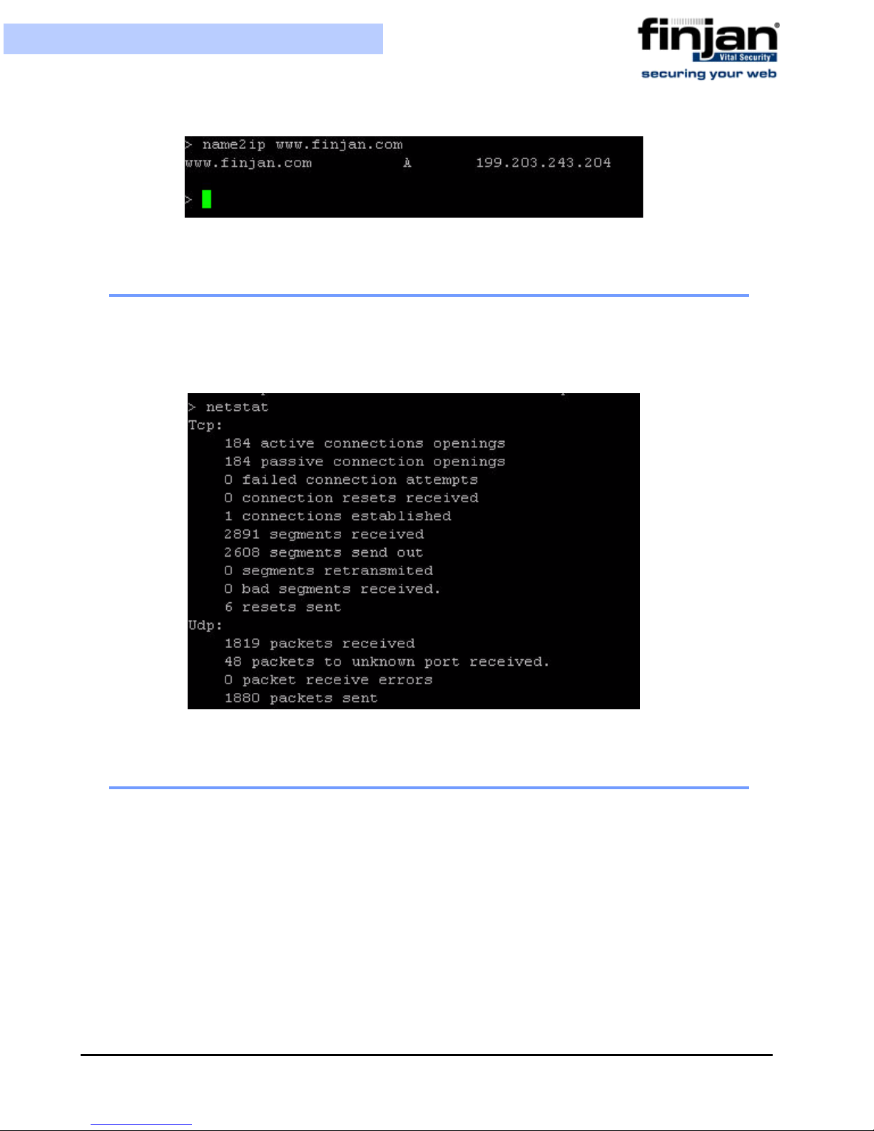
5.7 name2ip
The name2ip command displays the IP address associated with a given hostname. Enter th e
name2ip command followed by a hostname to display the associated IP address.
Chapter 3 - Configuring the Vital Security Appliance46
Setup and Configuration Guide
Figure 3-49: name2ip
5.8 netstat
The netstat command is a useful tool for checking your network configuration and activity.
It displays the status of network connections on either TCP, UDP, RAW or UNIX sockets to
the system.
5.9 ping
Use the ping command to check the network connectivity - for example after using netconf.
Chapter 3 - Configuring the Vital Security Appliance
Figure 3-50: netstat
47

Setup and Configuration Guide
Figure 3-51: ping
5.10 poweroff
The poweroff command enables you to remotely shut down the appliance.
IMPORTANT: Physical access to the appliance is needed to bring the system back
online for all models except the NG-8000.
5.11 reboot
The reboot command enables you to remotely reboot the appliance.
5.12 restart_role
The restart_role command restarts all role services.
Figure 3-52: restart role
5.13 save_support_logs
The save_support_logs command saves support logs in the support directory.
Chapter 3 - Configuring the Vital Security Appliance48

Setup and Configuration Guide
Figure 3-53: save_support_logs
5.14 setup
The setup command assists you in setting up the device for the first time. It guides you to
perform all the necessary steps to establish a working device. You can choose to rerun the
Setup command to repeat the initial configuration commands at any time.
5.15 show
The show command shows system or service status. The show command includes the
show_config, show_network, show_service, show_dbsize, show_route, and show_time.
Chapter 3 - Configuring the Vital Security Appliance
Figure 3-54: setup
49

Setup and Configuration Guide
Figure 3-55: show
5.15.1 show_config
The show_config command shows the current configuration.
Figure 3-56: Show_config
5.15.2 show_network
The show_network command shows the current network configuration. This includes: defined
interfaces, DNS configuration, DNS cache and current hostname.
Chapter 3 - Configuring the Vital Security Appliance50

Setup and Configuration Guide
Figure 3-57: show_network
5.15.3 show_service
The show_service command allows system administrators to view the service
configuration status.
Enter the show_service command.
Figure 3-58: show_service
The following commands are available:
show_service_all: This option displays the service configuration status for all the
available services.
Chapter 3 - Configuring the Vital Security Appliance
51

Figure 3-59: show_service_all
show_service_snmpd: This option displays the service configuration status for snmpd.
Figure 3-60: show_servic e_ s nmpd
show_service_ssh: This option displays the service configuration status for ssh.
Figure 3-61: show_service_ssh
5.15.4 show_dbsize
The show_dbsize command shows the file size of the databases connected with your
appliance.
5.15.5 show_route
The show_route command allows system administrators to view the Kernel IP routing table.
Enter the show_route command.
Figure 3-62: show_dbsize

Setup and Configuration Guide
Figure 3-63: show_route
5.15.6 show_time
The show_time command allows system administrators to view the time, date, time zone
ad ntp settings.
Enter the show_time command.
Figure 3-64: show_time
5.16 supersh
The supersh command enables root access to the appliance. This command is reserved
for Finjan Support only.
5.17 tcpdump
The tcpdump command allows the user to intercept and display TCP/IP and other packets
being transmitted or received over a network to which the computer is attached. It writes all
the information into a tcpdump file. This file can then be downloaded for further analysis.
Up to 4 files of 100 MB each are kept. When the fourth file gets full, the first file is deleted
(i.e. cyclic progression). SFTP, such as WinSCP, is required in order to download the files.
Chapter 3 - Configuring the Vital Security Appliance
Figure 3-65: tcpdump
53

Setup and Configuration Guide
5.18 top
The top command displays all the running processes, and updates the display every few
seconds, so that you can interactively see what the appliance is doing.
Figure 3-66: top
5.19 traceroute
The traceroute command displays the route over the network between two systems, listing all
the intermediate routers a connection must pass through to get to its destination. It can help
you determine why connections to a given server might be poor, and can often help you figure
out where exactly the problem is.
Chapter 3 - Configuring the Vital Security Appliance54

Setup and Configuration Guide
Figure 3-67: traceroute
5.20 uptime
The uptime command produces a single line of output that shows the current time, how
long the system has been running (in minutes) since it was booted up, how many user
sessions are currently open and the load averages.
Figure 3-68: uptime
5.21 vmstat
The vmstat command reports statistics about kernel threads, virtual memory, disks, traps
and CPU activity. Reports generated by the vmstat command can be used to balance
system load activity.
Chapter 3 - Configuring the Vital Security Appliance
55

Setup and Configuration Guide
Figure 3-69: vmstat
5.22 w
The w command shows who is currently logged on and the current command they are
running.
Figure 3-70: w
5.23 wget
The wget command allows you to download web files using HTTP, HTTPS and FTP
protocols.
Figure 3-71: wget
6 First Login to the Management Console
When you first log in to the Management Console, you will b e d irected to th e L icen se screen.
A single license key can be used for multiple Policy Servers. It can also be re-used for
situations where the administrator needs to reinstall the system.
Evaluation License: When entering the Management Console for the first time, an
installation Wizard will run and the administrator must enter a license key. An evaluation key
entitles you to a 30 day evaluation period with full Vital Security functionality. Once the 30
days evaluation period has passed, Vital Security will start forwarding Internet content
through without scanning it. The Management Console will be disa bled until the administrator
Chapter 3 - Configuring the Vital Security Appliance56

Setup and Configuration Guide
enters a permanent license key.
NOTE: The Policy Server will update Finjan Headquarters as to the status of the
License. This information is confidential and will be kept at the Finjan Financial
offices.
Ten days before the evaluation license is about to expire, an informative message will be
displayed.
Permanent License: A permanent license is generated by Finjan and sent to the
customer. Its expiration date is based on a service agreement with the customer. Starting
three months before the expiration date, the administrator will receive notifications that the
license needs to be renewed. Once the license has expired, you will be treated to a thirty
day grace period where traffic will be scanned but administrators will have very limited
access to the Management Console. After the grace period is complete, Vital Security will
no longer function as required.
Â
To enter your new License Key:
1. Enter the license key provided by Finjan and click Continue.
2. Read through the EULA agreement and check the I accept checkbox.
3. Click OK to finish.
7 Update Mechanism
The Update mechanism periodically checks Finjan's Web site and automatically displays
any available updates via the Management Console for the administrator. There are three
categories of updates:
Security Updates Behavior scanning logic and vulnerability data: These can be
configured automatically. Vital Security behavior profiling data and security
processors are updated automatically from the Finjan site as soon as new Windows
vulnerabilities are discovered. Vulnerability protection typically arrives before viruses
that exploit the vulnerability are released.
Finjan Software is a market leader in malicious mobile code. Malicious Code
Research Center at Finjan employs dedicated experts who work around the clock to
identify new Windows vulnerabilities and exploits, enabling real day-zero protection.
OS Version updates: Automatic downloading from the Finjan Web site can be
enabled/disabled via the Management Console. You will be notified automatically
when updates become available so that you can install them and keep your system
up-to-date.
Third-party security engines: Vital Security incorporates best-of-breed third-party
engines (anti-virus and URL categorization). These applications rely on frequent and
regular updates, and these are downloaded and installed automatically by the autoupdate feature.
Chapter 3 - Configuring the Vital Security Appliance
57

Setup and Configuration Guide
7.1 Installing Updates
Updates are installed via the Vital Security Management Console, which runs on the All in
One appliance or Policy Server at the default HTTPS port (443). It is recommended to check
for updates each time that you use the system, in the event that security and functional
updates have been released either since the product was installed or since the last check was
performed.
7.1.1 Configuring Next Proxy for Updates
If you are connecting your All-in-One appliance or Policy Server to the Internet via a proxy
server, you must configure the proxy in the Proxy Server and Port fields in the Management
Console on the Administartion
Save and Commit Changes to ensure that the change takes effect.
7.1.2 Configuring the Firewall for Automatic Updates
Æ
UpdatesÆUpdates Configuration tab, and then click
In order to enable Automatic updates for the NG Appliance Series, the Firewall should be
opened for the Policy Server, using the HTTPS (port 443) protocol in the outgoing direction.
There are two destination URLs:
https://updateNG.finjan.com/remote_update
https://mirror.updateNG.finjan.com/remote_update
The following table details the ports needed for configuring Automatic Updates:
Description Port Number
All in one machine (web traffic ports)
Only HTTP, FTP and HTTPS from
LAN to WAN
Additional ports to open from LAN to DMZ
Manager - transfer of policy
updates, and other updates
Manager – secure transfer of policy
updates, and other updates
Log traffic (from server) 8000
Secure Log traffic 8001
SNMP queries (if enabled) 161 UDP
Additional ports to open from DMZ and LAN
SNMP trap (if enabled and
configured to send traps to the
SNMP Manager on the LAN)
5222
5224
162 UDP
7.1.3 Offline Updates
Customers who are using the appliance in an isolated network that is not connected to the
Internet, can download any updates from the Finjan update site. These updates can be
Chapter 3 - Configuring the Vital Security Appliance58

Setup and Configuration Guide
manually downloaded and saved onto a removable media (e.g. CD) which should then be
connected to the offline computer where you manage the Policy Server. From the
Management Console, you can install the updates using the Import Local Updates option.
This feature requires a special license. Please contact your Finjan representative for
further details.
8 Routing Traffic through the Appliance
You can use any of the following proxy setting alternatives, or configure proxy access to be
transparent.
8.1 Configuring Workstations for Routing Traffic through the
Appliance
Manual Configuration per Individual User
In Internet Explorer, select Tools
Settings and click the Advanced button in the Proxy Servers area. In the Proxy
Settings dialog box, enter the IP address of the Vital Security Scanning Server o r Load
Balancer in the HTTP field.
Customized Installation of Internet Explorer
Download the Microsoft tool IAEK6 in order to enable customized installation of
Internet Explorer for all users.
Group Policy Manager
In the Microsoft Active Directory, create a Group Policy Object (GPO) that
configures which proxy to use per machine or user.
Login Scripts
For older legacy systems such as NT4, you can use login scripts to configure the
proxy server.
In Firefox, select Tools
Settings tab, and can manually specify the IP address(es) of the proxy or use
automatic proxy settings via a URL.
Æ
Options and click on the Network tab. Click on the
Æ
Internet Options Æ Connections Æ LAN
8.2 Transparent Proxy
Vital Security can be deployed as a transparent proxy - for HTTP, HTTPS and FTP, in
conjunction with a third-party content switch or a layer-4 router in the network. This means
that all HTTP traffic is routed, at packet level, through the content switch to the Vital
Security Appliance. End-users are not aware of this and have the same su rfing experience
as if they were communicating directly with the Web server.
When deployed as a transparent proxy, there is no need to configure proxy settings of
individual end-user browsers. However, because of the transparency, the appliance is not
Chapter 3 - Configuring the Vital Security Appliance
59

able to perform proxy-level user authentication.
Â
To enable working in transparent mode:
Setup and Configuration Guide
1. In the Vital Security Management Console, navigate to Administration
Æ
Settings
2. In the selected Scanning Server, choose the General node.
3. Click Edit and select the Enable Transparent Proxy Mode.
4. Define the ports to be used for the scanned traffic.
Finjan Devices Æ Scanning Server.
Æ
System
Figure 3-72: Transparent Proxy Mode
Click Save and click
5.
The following diagram illustrates the deployment.
Chapter 3 - Configuring the Vital Security Appliance60

Setup and Configuration Guide
9 Working with HTTP
In order for browsers or other appliances to be protected by Vital Security, the Vital
Security must be configured as the Proxy Server. Working with the Vital Security you can
configure your browser for maximum efficiency (number of requests per second) in
Microsoft Internet Explorer by selecting Tools
selecting both Use HTTP 1.1 and Use HTTP 1.1 through proxy connections.
9.1 HTTP Proxies
Vital Security can communicate with any RFC-compliant Web proxy.
9.2 Working with Caching Proxies
When a caching proxy is in use, Vital Security can be integrated either upstream or
downstream from the cache proxy in the network.
Figure 3-73: Transparent Proxy
Æ
Internet Options Æ Advanced and
9.2.1 Downstream
When Vital Security is positioned downstream of the cache proxy, the cached content is
rescanned for every request. This topology clearly works for systems with user/group
policies that differentiate between the sites that the different users/groups may visit, as
every request is submitted to Vital Security and scanned against the relevant policy.
This means that:
Chapter 3 - Configuring the Vital Security Appliance
61

Setup and Configuration Guide
Every request is scanned with the latest security updates, even if the content was cached
before the last update.
Traffic scanned initially by Vital Security is cached and subseque ntly forwarded again by
the caching proxy in line with additional user requests. Each time this happens, the
content is rescanned by Vital Security. The resulting drain o n re sources should be ta ken
into account regarding performance.
Every additional request for cached content is subjected to the policy specific to the user
making the new request. Policy changes will always be implemented because all
content, even if it comes from the cache, is scanned again by Vital Security.
All accesses to cached content are subject to the logging policy, and are potentially
logged by Vital Security.
9.2.2 Upstream
When Vital Security is positioned upstream from the cache, traffic is scanned only once, and
is then cached and forwarded directly to the users. This is optimal for organizations that use a
single policy for all Internet access, and do not apply different policies to different users/
groups. This is not suitable for per user/group policies that differentiate between the sites
visited by users/groups. (In such cases, you may consider working with ICAP.)
This means that:
Because content is only scanned once, there is less drain on resources, leading to
improved performance.
Cached content is not subject to the latest security updates, nor to policy changes.
Vital Security cannot log accesses to cached content.
9.3 HTTP Authentication
Authentication enables the following:
Ensures that only requests from bona-fide users are handled/processed.
Enables the allocation of different policies to different users and/or groups by matching
authentication data to user identifiers in the system.
Ensures that all logged transactions are attributed to the corresponding user.
Authentication policies are covered in the Policies chapter of the Management Console
Reference Guide.
10 Working with ICAP
ICAP stands for Internet Content Adaptation Protocol. ICAP is used in conjunction with
caching proxies such as Network Appliance NetCache or Blue Coat Proxy SG. ICAP
configurations typically require significant tuning to maximize the benefits.
Chapter 3 - Configuring the Vital Security Appliance62

Setup and Configuration Guide
10.1 Why work with ICAP?
One of the reasons is that if you are working with a caching proxy that supports the ICAP
protocol, you can achieve significant performance benefits from configuring Vital Security
as an ICAP server rather than an HTTP proxy. Working with ICAP means that you don’t
need to change the topology but rather integrate our product with ICAP. You can configure
specific content to be sent for scanning. The default is to scan everything.
10.2 Vital Security as an ICAP Server
When deployed in the ICAP environment, the ICAP client typically provides user
credentials and Vital Security does not have to authenticate users.
Figure 3-74: Vital Security as an ICAP Server
10.3 REQMOD – RESP MOD Deployment
As an ICAP Server, Vital Security can provide both REQMOD (Request Modification) and
RESPMOD (Response Modificat ion) services.
The service name for REQMOD is Finjan_REQMOD.
The service name for RESPMOD is Finjan_RESPMOD.
Vital Security can receive both REQMOD and RESPMOD requests.
Here is an example of an ICAP URL for the REQMOD service:
Chapter 3 - Configuring the Vital Security Appliance
63

Setup and Configuration Guide
icap://192.168.2.153:1344/Finjan_REQMOD
NOTE: When working with RESPMOD, REQMOD must be enabled.
Vital Security can also work in REQMOD only, for example, f or performing URL filtering, but in
this case, the actual incoming content is not scanned.
Configuration of a Vital Security scanning server as an ICAP server is carried out via the
Management Console.
NOTE: If there is no direct Internet access, in order to perform pre-fetching of
Java classes for Applet scanning, ALL Scanning Servers must have the next proxy
configured. If you are using ICAP, ensure that the NG Appliance Scanning Server
appears on the Access List.
10.4 ICAP Clients
There are a number of ICAP Clients that support Vital Security:
Network Appliance NetCache Series
Blue Coat Proxy SG Series
Chapter 3 - Configuring the Vital Security Appliance64

C
ONFIGURING
This chapter describes the configuration of the following ICAP clients:
Network Appliance NetCache Series (NetApp)
Blue Coat
ICAP C
1 Network Appliance NetCache Series (NetApp)
C HAPTER
LIENT S
In order to configure Vital Security to work with NetApp, follow the procedures below in the
order given.
Â
To configure NetApp via Vital Se curity:
1. In the Vital Security Management Console, select Administration
Æ
Settings
2. In the Devices screen, select the Scanning Server with which you are working, and
then select ICAP.
Finjan Devices.
Æ
System
Chapter 4 - Configuring ICAP Clients 65
Figure 4-1: Devices - ICAP

Setup and Configuration Guide
3. Click on Edit in the right hand pane.
4. Select Enable ICAP for Device.
5. In the Access List tab, click on and select Add Row from the drop-down menu.
Figure 4-2: Access List
6.
Select NetApp from the Type drop-down list.
7. Add the Source IP address of the ICAP client and add the weight. Note that the
weight is in percentage. If there is only one ICAP client, enter 100 in the weight field.
8. In the ICAP Service tab, enter the IP Address of the Scanning Server.
9. Click Save to apply changes, else Cancel. Select Commit changes.
Â
To configure NetApp via the NetApp web interface:
1. Log in to the NetApp Web interface. The ICAP Setup window is displayed with the
General tab open.
2. Click Setup.
3. Click ICAP
4. Select the Enable Version 1.0 option.
Æ
ICAP 1.0 in the left hand pane.
Chapter 4 - Configuring ICAP Clients66

Setup and Configuration Guide
Figure 4-3: ICAP Setup - General
5.
Open the Service Farms tab.
6. Press the New Service Farm button to create a new ICAP Service.
Â
To configure an ICAP Service Farm:
1. To set a REQMOD service, ensure that the following conditions are met:
In the Vectoring Point field, select REQMOD_PRECACHE.
In the Services field set the service URL:
icap://[Vital Security’s IP]:[ICAP port]/Finjan_REQMOD on
2. To set a RESPMOD service, ensure that the following conditions are met:
In the Vectoring Point field select respmode_precache
In the Services field set the service URL:
icap://[Vital Security’s IP]:[ICAP port]/Finjan_RESPMOD on
Several services can be defined in Services and load-balanced by NetApp.
Chapter 4 - Configuring ICAP Clients
67

Setup and Configuration Guide
Once the services have been configured in the Service Farms, Access Control List
3.
rules should be defined to include these services.
Figure 4-4: New ICAP Service Farm
Chapter 4 - Configuring ICAP Clients68

Setup and Configuration Guide
With every ICAP settings change, NetApp sends an OPTIONS request to the relevant
ICAP Service.
2 Blue Coat
To configure Vital Security to work with Blue Coat, please follow all the procedures below
in the order given.
Â
To configure Blue Coat via Vital Security:
1. In the Vital Security Management Console, select Administration
Settings
2. In the Devices screen, select the Scanning Server with which you are working, and
then select ICAP.
3. Click on Edit in the right hand pane.
4. Select Enable ICAP for Device.
Figure 4-5: Access Control Lists
Æ
Finjan Devices.
Æ
System
Chapter 4 - Configuring ICAP Clients
69

Setup and Configuration Guide
5. In the Access List tab, click on and select Add Row from the drop-down menu.
Figure 4-6: Blue Coat Configuration
6.
Select Blue Coat from the Type drop-down list.
7. Add the Source IP address of the ICAP client and add the weight. Note that the
weight is in percentage. If there is only one ICAP client, enter 100 in the weight field.
8. In the ICAP Service tab, enter the IP Address of the Scanning Server.
9. Click Save to apply changes, else Cancel. Select Commit changes.
Â
To configure Blue Coat via the Blue Coat Web interface
1. Log in to the Blue Coat web interface.
Chapter 4 - Configuring ICAP Clients70

Setup and Configuration Guide
Figure 4-7: Blue Coat Main Screen
2.
Navigate to the Management Console.
Figure 4-8: Blue Coat Management Console
Chapter 4 - Configuring ICAP Clients
71

Setup and Configuration Guide
NOTE: If, at any time during the session, the Java Plug-in Security Warning appears,
select Grant this session to continue.
Â
To define REQMOD (Request Modification) Service.
1. From the Blue Coat Management Console, select External Services
Æ
ICAP. The
ICAP Services screen is displayed on the right.
2. At the bottom of the ICAP Services screen, click New. The Add List Item dialog box is
displayed.
3. Enter a name and click OK. For instance, Finjan_Reqmod. The External Services
window is displayed again with the name you have selected.
Figure 4-9: Blue Coat ICAP Services
Click Edit. The Edit ICAP Services dialog box is displayed.
4.
Chapter 4 - Configuring ICAP Clients72

Setup and Configuration Guide
Chapter 4 - Configuring ICAP Clients
Figure 4-10: Edit ICAP Services
73

Setup and Configuration Guide
The following table describes the field data to be entered:
Field Name Field Data to be entered
ICAP Version Select 1.0 from the dropdown list
Server Type Enter the following: icap://<scanner IP
(ICAP server)>:<scanner port
(default=1344)>/Finjan_REQMOD. For
example, icap://192.168.90.10:1344/
Finjan_REQMOD
Method Supported Click the request modification radio
button.
5. If your Vital Security scanner is up and running, then press the Sense Settings
button and then OK. A confirmation message appears; click OK again.
(If, on the other hand, your Vital Security scanner is not yet up and running, then click
OK only to continue. In this case, you should return to this dialog box later on when
Vital Security is up and running in order to select Sense Settings)
6. In the Edit ICAP Services box, select the Authenticated User checkbox and then
click OK.
7. Click Apply in the ICAP Services screen to complete the configuration.
Â
To activate the REQMOD Service:
1. In the Blue Coat Management Console, select Policy
Æ
Visual Policy Manager.
The Visual Policy Manager is displayed.
Chapter 4 - Configuring ICAP Clients74

Setup and Configuration Guide
Figure 4-11: Visual Policy Manager Launch
2.
Click Launch and the Visual Policy Manager dialog box is displayed.
Figure 4-12: Visual Policy Manager Dialog Box
3.
From the Main Menu Bar, select Policy Æ Add Web Access Layer, and the Add
New Layer dialog box is displayed.
Chapter 4 - Configuring ICAP Clients
75
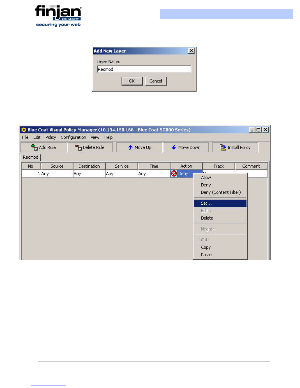
Setup and Configuration Guide
Figure 4-13: Add New Layer Dialog Box
4.
Add in the required name and click OK. The Visual Policy Manager is displayed with
a new Web Access Layer.
Figure 4-14: Web Access Layer Added
In the Action column, right-click on Deny, and then select Set. The Set Action
5.
Object dialog is displayed.
6. Click New.
Chapter 4 - Configuring ICAP Clients76

Setup and Configuration Guide
Figure 4-15: Edit ICAP Request Service
7.
In the Add ICAP Request Service Object window, select the Use ICAP Request
Service checkbox.
Chapter 4 - Configuring ICAP Clients
77

Setup and Configuration Guide
Figure 4-16: Add ICAP Request Service Object
From the drop-down list, select the REQMOD service you have defined, and click
8.
OK.
9. Go back to the Set Action Object dialog box, and click OK.
10.Click the Install Policy button in the Visual Policy Manager.
Â
To define RESPMOD (Response Modification) Service:
1. Carry out the same steps as the above procedure. When adding a new layer to the
Blue Coat policy, choose a Add Web Content Layer instead of Add Web Access
Layer.
2. Choose Respmod instead of Reqmod where relevant. For example:icap://
192.168.90.10:1344/Finjan_RESPMOD
Chapter 4 - Configuring ICAP Clients78

I
NST ALLATION
1 Installing your Vital Security Appliance
An update can be performed by restoring the configuration (after fully installing from USB).
Â
To install a Release using a USB key on NG-5000:
1. Attach a bootable USB flash device, and a USB-keyboard and VGA monitor to the
appliance whilst it is still switched off.
A PPENDIX
D
ET AILS
2. Power on the appliance. The appliance will read automatically from the USB key.
3. When the Finjan screen appears, type yes to continue with the process.
Appendix A - Installation Details 79

Setup and Configuration Guide
Figure A-1: Finjan installation screen
4. Let the installation run – it will take approximately 10 minutes. After this time, the
appliance will reboot.
5. When the Finjan installation screen reappears, remove the USB key. Reboot the
appliance by pressing Ctrl + Alt + Delete.
Set up the configuration as required via the Limited Shell as described in
Initial Setup of your
Vital Security Appliance using Limited Shell.
Â
To install a Release using a USB key on NG-6000/NG-8000:
1. Attach a bootable USB flash device, and a USB-keyboard and VGA monitor to the
appliance whilst it is still switched off.
2. Power on the appliance.
3. Press F12 to choose the Boot Device Configuration Menu. The boot device menu
appears.
4. In the Boot Device menu, use the arrow key to select USB Key/Disk and press Enter.
5. In the screen that appears, select the required USB key and press Enter.
Appendix A - Installation Details80

Setup and Configuration Guide
6. In the next screen, in the Persistent field, ensure that it says This boot only and
press Enter.
7. In a few minutes, the Finjan screen appears, type yes to continue with this
process.
8. When the Finjan screen appears, type yes to continue with the process.
Figure A-2: Finjan installa tio n scre en
9. Let the installation run – it will take approximately 20 minutes. After this time, the
appliance will reboot.
10.When the Finjan installation screen reappears, remove the USB key. Reboot the
appliance by pressing Ctrl + Alt + Delete.
11.Set up the configuration as required via the Limited Shell as described in Initial
Setup of your Vital Security Appliance using Limited Shell.
NOTE: For information on installing version 9.0 on older appliances, please
For
contact Finjan Support.
Appendix A - Installation Details
81

Setup and Configuration Guide
1.1 Remote Installation on NG-8000
What you need:
Java™ 6 installed on your computer
DVD reader
Internet connection to the BladeCenter Management Module with a valid IP address
Â
To install a Release remotely onto a BladeCenter:
1. On your local PC, insert the DVD with the release on it into the DVD slot.
2. In your Internet browser, enter the Management Net address. For example, HTTP://
10.194.150.75
3. Enter the user name: USERID and password: PASSW0RD (Note that there is a zero
in PASSW0RD.)
In the BladeCenter Management Module, on the left-pane, under Blade Tasks, select
4.
Remote Control. Next, click Start Remote Control. A new window opens.
Figure A-3: Login Screen
Appendix A - Installation Details82

Setup and Configuration Guide
Figure A-4: Remote Control - Sta rt Remo t e Cont rol
In the Remote Control window, select the required Blade from the Media Tray
5.
drop-down list. In this example, we are working with Blade 7.
Figure A-5: Remote Control: Media Tray
6.
In the Available Resources window, scroll down and select CD-Rom. Using the
arrows, move it right to the Selected Resources window and click Mount All.
Appendix A - Installation Details
83

Setup and Configuration Guide
Figure A-6: Selected Resources - Mount All
In the Remote Console section, in the KVM field, scroll down to the Blade7 option
7.
(See figure above).
8. Switch over from the Remote Control screen to the Main Management Screen and
click Power/Restart on the left pane. Selct Blade7 and click Restart Blade.
Appendix A - Installation Details84

Setup and Configuration Guide
9.
Switch back over to the Remote Control screen, and wait for the Server to boot up
from the DVD. Type yes to start the installation.
Appendix A - Installation Details
Figure A-7: Restart Blade
85

Setup and Configuration Guide
Figure A-8: Finjan Vital Security Installation Security
10.
Let the installation run – it will take approximately 10 minutes. After this time, the
appliance will reboot.
11.When the Finjan installation screen reappears, remove the DVD. Reboot the
appliance by pressing Ctrl + Alt + Delete.
12.Set up the configuration as required via the Limited Shell as described in Initial Setup
of your Vital Security Appliance using Limited Shell
1.2 Post-Installation Bonding Script on NG-8000
In order to support topologies where switch redundancy is required, a special bonding script
(also known as teaming) has been designed for the NG-8000. This should only be run by a
Finjan certified engineer. Please contact Finjan Support for details.
Appendix A - Installation Details86

P
OST-INST ALLATION
1 System Hardening
After the installation and configuration of the Vital Security system, it is highly
recommended to “harden” (tighten up) the Policy Server and Scanning Server in order to
prevent unauthorized access to the system.
S
YSTEM
A PPENDIX
H
ARDENING
1.1 Policy Server
The procedures below shows how to harden the Policy Server by denying unauthorized
access to it.
1.1.1 Management Access List
Vital Security provides the ability to configure a Management access list from the
Management Console. The access list ensures that only restricted IP addresses have
access to the system for management. The Access list is not enabled by default since the
administrator would not be able to access the system due to the fact that Administrator
subnets are not known before the installation. Once the access list is enabled, all access
from unknown IPs is disabled.
Â
To configure a Management Access List:
1. Navigate to Administration
Æ
Access List.
2. Click Edit to enable the screen for editing mode.
3. Select Use Access List.
4. In the Management Access List, click on the plus icon and in the row provided
enter the relevant IP addresses.
Æ
System Settings Æ Finjan Devices Æ <IP Address>
5. Click Save and click .
Appendix B - Post-Installation System Hardening 89

Setup and Configuration Guide
1.1.2 Management Console Password
The default password provided is “finjan”. It is recommend to change the default password as
soon as possible.
Â
To change the Management Console password:
1. Navigate to Administration
2. Click Edit to enable the screen for editing.
3. Enter a password in the New Password field and repeat in the Confirm Password
Æ
Administrators Æ admin.
field.
4. Click Save and click .
1.1.3 Default SNMP v2 Community String
The default SNMP v2 Read-Only community string is 'finjan'. Since most attack tools try to
use the default well-known community strings, it is recommended to change it.
Â
To change the SNMPv2 Community String:
1. Navigate to Administration
2. Click Edit to enable the screen for editing.
3. In the community field, change the word public.
4. Click Save and click .
NOTE: This changes the community string for the Scanning Servers as well.
Æ
Alerts Æ SNMP Æ SNMP Version.
This ch
1.1.4 User Access to the Scanning Servers
Vital Security provides the ability to configure a Users access list from the Management
Console. The access list ensures that only authorized IP addresses are allowed to access the
Scanning Servers.
Â
To configure a Users Access List:
1. Navigate to Administration
Access List.
2. Click Edit to enable the screen for editing mode.
3. Select Use Access List.
4. In the Users Access List, click on the plus icon and in the row provided enter the
relevant IP addresses.
5. Click Save and click .
Æ
System Settings Æ Finjan Devices Æ <IP Address> Æ
Appendix B - Post-Installation System Hardening90

Setup and Configuration Guide
1.2 Scanning Servers
The procedure below shows how to harden the Scanning Servers by denying unauthorized
access to them
1.2.1 Proxy IP Address
When the Scanning Server has multiple IP addresses (whether on a single network
interface or multiple network interfaces) it is recommended to limit access to the Scanning
Server via the interface that is being used by the end-users.
Â
To limit access via a single IP address:
1. In the Management Console, navigate to Administration
Finjan Devices
Port.
2. Click Edit to enable the screen for editing mode.
3. Select Enable HTTP for Device.
4. Enter the required IP in the Proxy IP Address field. The Scanning Server will not
accept requests from any other IP address.
5. Click Save and click .
NOTE: If the Scanning Server is also scanning HTTPS traffic, then add the
Æ
<IP Address> Æ Scanning Server Æ HTTP Æ Proxy IP and
Æ
System Settings Æ
required IP in the HTTPS - Proxy IP Address field.
1.2.2 Management Access List
Vital Security provides the ability to configure a Management access list from the
Management Console. The access list ensures that only restricted IP addresses have
access to the system for management. The Access list is not enabled by default since the
administrator would not be able to access the system due to the fact that Administrator
subnets are not known before the installation. Once the access list is enabled, all access
from unknown IPs is disabled.
Â
To configure a Management Access List:
1. In the Management Console, navigate to Administration
Finjan Devices
2. Click Edit to enable the screen for editing mode.
3. Select Use Access List.
4. In the Management Access List, click on the plus icon and in the row provided
enter the relevant IP addresses.
Appendix B - Post-Installation System Hardening
Æ
<IP Address> Æ Access List.
Æ
System Settings Æ
91

Setup and Configuration Guide
5. Click Save and click .
1.3 Nortel Switches (Applicable only to NG-8000 Series)
Nortel Switch (both Layer 2-3 and Layer 2-7) has to be hardened as well in order to limit
unauthorized access to it and also in order to secure the communication between the
management station and the switch.
1.3.1 Defaults SNMP Community String
SNMP access to the Nortel switch can be addressed as follows:
It can be completely disabled by issuing a "/cfg/sys/access/snmp disabled" command or
set to read-only with "/cfg/sys/access/snmp read-only".
The write community strings can be modified using "/cfg/sys/ssnmp/rcom" and "/cfg/sys/
ssnmp/wcomm".
NOTE: Configuring SNMPv3 on the Scanning Servers enables encrypted access
and can more precisely limit the objects that may be accessed. However - if
SNMPv3 is enabled, the System Dashhboard will not show the relevant
information.
1.3.2 Telnet and HTTP Access to the Switch
Telnet and HTTP access to the switch should be disabled in order to prevent management via
unsecured communication by enabling SSH access instead. Enabling SSH on the switch
means that all switch management will be carried out through SSH and not via the
Management module
1.3.3 Default User and password
The default user and password for the Nortel switch is 'admin'. It is highly recommended to
change the default password. In order to do so use the command /cfg/sys/access/user/
admpw
You will be prompted to enter the existing password (default “admin”) once and the new
password twice. Don´t forget to apply and save your settings.
Appendix B - Post-Installation System Hardening92
 Loading...