

finjan Vital Security NG-1000, Vital Security NG-5000, Vital Security NG-6000, Vital Security NG-8000 Installation And Setup Manual

Vital Security™ Appliance Series
NG-1000/NG-5000/NG-6000/NG-8000
Installation
and
Setup Guide

Installation and Setup Guide
Vital Security™ Appliance Series NG-1000/NG-5000/NG-6000/NG-8000 Installation and Setup
Guide
© Copyright 1996 - 2007. Finjan Inc. and its affiliates and subsidiaries (“Finjan”). All rights
reserved.
All text and figures included in this publication are the exclusive property of Finjan and are for your
personal and non-commercial use. You may not modify, copy, distribute, transmit, display, perform,
reproduce, publish, license, create derivative works from, transfer, u se or se ll any p art of i ts con tent
in any way without the express permission in writing from Finjan. Information in this document is
subject to change without notice and does not present a commitment or representation on the part of
Finjan.
The Finjan technology and/or products and/or software described and/or referenced to in this
material are protected by registered and/or pending patents including U.S. Patents No. 6092194,
6154844, 6167520, 6480962, 62 09 10 3, 6298446, 6353892, 680478 0, 69 22693, 6944822, 6993662,
6965968, 7058822, 7076469, 7155743, 7155744 and may be protected by other U.S. Patents,
foreign patents, or pending applications.
Finjan, Finjan logo, Vital Security, Vulnerability Anti.dote and Window-of-Vulnerability are
trademarks or registered trademarks of Finjan. Sophos is a registered trademark of Sophos plc.
McAfee is a registered trademark of McAfee Inc. Kaspersky is a registered trademark of Kaspersky
Lab. SurfControl is a registered trademark of SurfControl plc. Microsoft and Microsoft Office are
registered trademarks of Microsoft Corporation. All other trademarks are the trademarks of their
respective owners. Q1 2007
For additional information, please visit www.finjan.com or contact one of our regional offices
:
USA: San Jose
2025 Gateway Place Suite 180 San Jose,
CA 95110, USA
Toll Free: 1 888 FINJAN 8
Tel: +1 408 452 9700 Fax: +1 408 452 9701
salesna@finjan.com
USA: New York
Chrysler Building
405 Lexington Avenue, 35th Floor
New York, NY 10174, USA
Tel: +1 212 681 4410 Fax: +1 212 681 4411
salesna@finjan.com
Israel/Asia Pacific
Hamachshev St. 1,
New Industrial Area Netanya, Israel 42504
Tel: +972 (0)9 864 8200
Fax: +972 (0)9 865 9441
salesint@finjan.com
Catalog number: VSNG_IASG 8.4.3
Europe: UK
4th Floor, Westmead House,
Westmead,
Farnborough, GU14 7LP, UK
Tel: +44 (0)1252 511118
Fax: +44 (0)1252 510888
salesuk@finjan.com
Europe: Germany
Alte Landstrasse 27, 85521
Ottobrun, Germany
Tel: +49 (0)89 673 5970
Fax: +49 (0)89 673 597 50
salesce@finjan.com
Europe: Netherlands
Printerweg 56
3821 AD Amersfoort
Netherlands
Tel: +31 318 693 272
Fax: +31 318 693 274
salesne@finjan.com
Email:support@finjan.com
Internet:www.finjan.com

C ONTENTS
1 About this Manual . . . . . . . . . . . . . . . . . . . . . . . . . . . . . . . . . . . . . . . . . . .1
2 Finjan Overview . . . . . . . . . . . . . . . . . . . . . . . . . . . . . . . . . . . . . . . . . . . . .3
Introduction . . . . . . . . . . . . . . . . . . . . . . . . . . . . . . . . . . . . . . . . . . . . . . . . . . . . . . . . 3
Appliance Types . . . . . . . . . . . . . . . . . . . . . . . . . . . . . . . . . . . . . . . . . . . . . . . . . . . . . . . . . . . .3
3 Getting Started . . . . . . . . . . . . . . . . . . . . . . . . . . . . . . . . . . . . . . . . . . . . . . 9
Management Console System Requirements . . . . . . . . . . . . . . . . . . . . . . . . . . . . . . 9
Operating Systems . . . . . . . . . . . . . . . . . . . . . . . . . . . . . . . . . . . . . . . . . . . . . . . . . . . . . . . . . . .9
Software Requirements . . . . . . . . . . . . . . . . . . . . . . . . . . . . . . . . . . . . . . . . . . . . . . . . . . . . . . .9
Connecting your Vital Security Appliance (NG-1000/NG-5000/NG-6000) . . . . . . 10
Installation . . . . . . . . . . . . . . . . . . . . . . . . . . . . . . . . . . . . . . . . . . . . . . . . . . . . . . . . . . . . . . . . .10
Configuration . . . . . . . . . . . . . . . . . . . . . . . . . . . . . . . . . . . . . . . . . . . . . . . . . . . . . . . . . . . . . . .10
Connection Procedure . . . . . . . . . . . . . . . . . . . . . . . . . . . . . . . . . . . . . . . . . . . . . . . . . . . . . . . .10
Update Mechanism . . . . . . . . . . . . . . . . . . . . . . . . . . . . . . . . . . . . . . . . . . . . . . . . . . 23
Installing Updates . . . . . . . . . . . . . . . . . . . . . . . . . . . . . . . . . . . . . . . . . . . . . . . . . . . . . . . . . . .23
Defining System Device Roles via the Management Console . . . . . . . . . . . . . . . . . 25
Connecting your Vital Security Appliance NG-8000 . . . . . . . . . . . . . . . . . . . . . . . . 27
Initial Procedures for the Policy Server . . . . . . . . . . . . . . . . . . . . . . . . . . . . . . . . . . . . . . . . . . .27
Initial Procedures for the Vital Security Scanning Server . . . . . . . . . . . . . . . . . . . . . . . . . . . . .28
Routing Traffic through the Appliance . . . . . . . . . . . . . . . . . . . . . . . . . . . . . . . . . . . 29
Configuring Workstations for Routing Traffic through the Appliance . . . . . . . . . . . . . . . . . . .29
Transparent Proxy . . . . . . . . . . . . . . . . . . . . . . . . . . . . . . . . . . . . . . . . . . . . . . . . . . . . . . . . . . .30
Working with HTTP . . . . . . . . . . . . . . . . . . . . . . . . . . . . . . . . . . . . . . . . . . . . . . . . . 30
HTTP Proxies . . . . . . . . . . . . . . . . . . . . . . . . . . . . . . . . . . . . . . . . . . . . . . . . . . . . . . . . . . . . . .31
Working with Caching Proxies . . . . . . . . . . . . . . . . . . . . . . . . . . . . . . . . . . . . . . . . . . . . . . . . .31
HTTP Authentication . . . . . . . . . . . . . . . . . . . . . . . . . . . . . . . . . . . . . . . . . . . . . . . . . . . . . . . . .32
Working with ICAP . . . . . . . . . . . . . . . . . . . . . . . . . . . . . . . . . . . . . . . . . . . . . . . . . 32
Why work with ICAP? . . . . . . . . . . . . . . . . . . . . . . . . . . . . . . . . . . . . . . . . . . . . . . . . . . . . . . .32
Vital Security as an ICAP Server . . . . . . . . . . . . . . . . . . . . . . . . . . . . . . . . . . . . . . . . . . . . . . .33
REQMOD – RESPMOD Deployment . . . . . . . . . . . . . . . . . . . . . . . . . . . . . . . . . . . . . . . . . . .33
ICAP Clients . . . . . . . . . . . . . . . . . . . . . . . . . . . . . . . . . . . . . . . . . . . . . . . . . . . . . . . . . . . . . . .34
4 Configuring ICAP Clients . . . . . . . . . . . . . . . . . . . . . . . . . . . . . . . . . . . . . . 35
Network Appliance Netcache Series (NetApp) . . . . . . . . . . . . . . . . . . . . . . . . . . . . 35
Blue Coat . . . . . . . . . . . . . . . . . . . . . . . . . . . . . . . . . . . . . . . . . . . . . . . . . . . . . . . . . 38
Contents i

Installation and Setup Guide
5 Advanced Settings . . . . . . . . . . . . . . . . . . . . . . . . . . . . . . . . . . . . . . . . . . .49
Introduction to Setup Console Advanced Settings . . . . . . . . . . . . . . . . . . . . . . . . . .49
Configuring Advanced Settings . . . . . . . . . . . . . . . . . . . . . . . . . . . . . . . . . . . . . . . . .49
Appliance Role . . . . . . . . . . . . . . . . . . . . . . . . . . . . . . . . . . . . . . . . . . . . . . . . . . . . . . . . . . . . . 51
Licensing . . . . . . . . . . . . . . . . . . . . . . . . . . . . . . . . . . . . . . . . . . . . . . . . . . . . . . . . . . . . . . . . . . 51
Custom Commands . . . . . . . . . . . . . . . . . . . . . . . . . . . . . . . . . . . . . . . . . . . . . . . . . . . . . . . . . . 52
Time Settings . . . . . . . . . . . . . . . . . . . . . . . . . . . . . . . . . . . . . . . . . . . . . . . . . . . . . . . . . . . . . . 57
Network Settings . . . . . . . . . . . . . . . . . . . . . . . . . . . . . . . . . . . . . . . . . . . . . . . . . . . . . . . . . . . 59
Change Password . . . . . . . . . . . . . . . . . . . . . . . . . . . . . . . . . . . . . . . . . . . . . . . . . . . . . . . . . . . 73
Restart Role . . . . . . . . . . . . . . . . . . . . . . . . . . . . . . . . . . . . . . . . . . . . . . . . . . . . . . . . . . . . . . . 74
Reboot/Shutdown Appliance . . . . . . . . . . . . . . . . . . . . . . . . . . . . . . . . . . . . . . . . . . . . . . . . . . 74
Active/Standby Policy Server . . . . . . . . . . . . . . . . . . . . . . . . . . . . . . . . . . . . . . . . . . . . . . . . . . 75
A Limited Shell . . . . . . . . . . . . . . . . . . . . . . . . . . . . . . . . . . . . . . . . . . . . . . . .77
B Installation CD . . . . . . . . . . . . . . . . . . . . . . . . . . . . . . . . . . . . . . . . . . . . . . .79
Contentsii

C HAPTER
A
BOUT THIS
Chapter Description
Chapter 1 About this Manual
Chapter 2 Overview - An introduction to Finjan's Vital Security
Appliance platform, including a brief overview of the
Vital Security Appliances NG-1000/NG-5000/NG6000/NG-8000.
Chapter 3 Getting Started – This section tells you everything you
need to know about getting started and lists the
necessary steps to be taken when installing and working
with your appliance.
This includes:
System requirements (hardware and software)
Information on supported protocols (HTTP and ICAP)
Configuration of end-user machines
Transparent proxy configuration
Connecting – describing the steps to be taken prior to
accessing the web-based Management Console
Chapter 4 Configuring the ICAP Clients – Discusses
configuration of Network Appliance (NetApp) and
Blue Coat
Chapter 5 Configuring Advanced Settings – This Chapter
describes how to use the Advanced Settings of the
Setup Console to manage the functionality of the
appliance
Appendix A Limited Shell – This Appendix describes the Limited
Shell feature.
Appendix B Installation CD – This Appendix details the installation
procedure using the Installation CD
M
ANUAL
Chapter 1 - About this Manual 1


1 Introduction
Cyber-threats are fast increasing and pose a serious and growing problem for corporate
networks, appearing in different forms and using a variety of tactics – viruses, worms,
Trojans, and more. New, ultra-fast viruses can infect your system within seconds, long
before traditional signature-based solutions can protect you. While waiting for anti-virus
companies to release a new virus signature, thousands of unprotected computers may have
already been infected, leaving no alternative other than to shut down the corporate network.
F
INJAN
C HAPTER
O
VERVIEW
Finjan's proactive behavior-inspection technology at the gateway provides protection by
examining active content behavior and identifying and blocking malicious mobile code
(viruses, worms, Trojan horses and a myriad of ever-developing attack types). Finjan’s
unique and patented proactive behavior inspection technology offers instant protection
against new virus, worm and malicious mobile code outbreaks without time-sensitive
signature-file updates, thus closing the Window-of-Vulnerability™ and providing
networks with true day-zero protection.
Vital Security - Finjan’s Integrated Security Platform - is a complete and integrated
Secure Content Management solution in which individual best-of-breed security
applications work together in concert to respond proactively to the changing security
threats of both today and tomorrow.
This section contains a brief overview of the Vital SecurityAppliances NG-1000/
NG-5000/NG-6000/NG-8000.
1.1 Appliance Types
This manual deals with the following Vital Security Appliances:
1.1.1 Vital Security Appliance Series NG-8000
This appliance is a specially configured chassis containing multiple hot swappable blades,
with redundant power supplies, disks etc. The Vital Security Operating System (VSOS) is
preinstalled and preconfigured.
Chapter 2 - Finjan Overview 3

Installation and Setup Guide
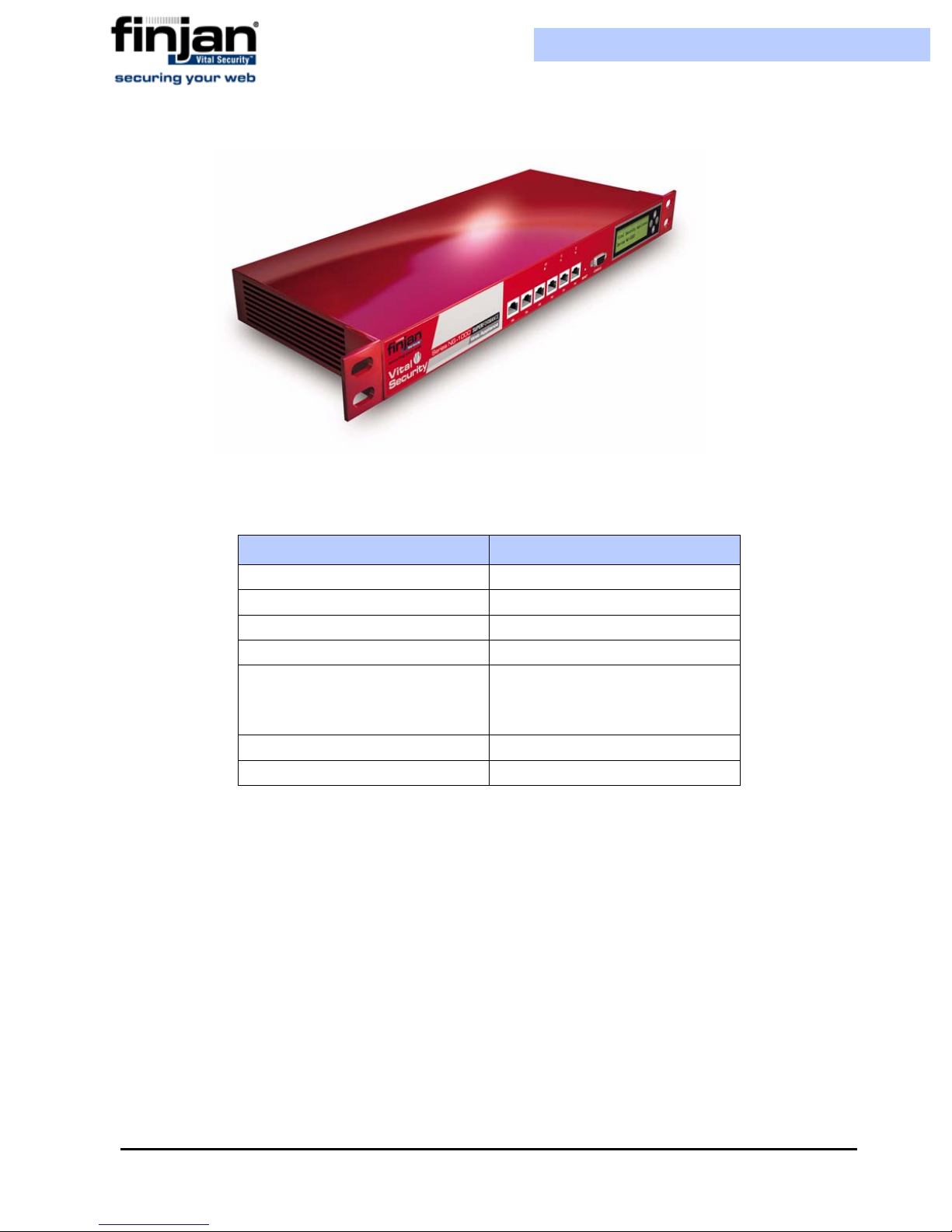
Figure 2-1: NG-8000 Superformance Appliance
The following table contains the hardware specifications for the NG-8000 appliance..
Component Specification
Memory 2 GB
Hard Drive 36 GB SAS (Web appliance)
2 x 73 GB SAS ( RAID 1)
(Policy Server)
CPU Xeon D 2 x 2.0GHz
Gigabit Ethernet NIC 2
NOTE: This document deals with the basic setup of the NG-8000 Appliance. Please
contact Finjan’s Support, or IBM for information about more advanced setup of the
Blade Center.
1.1.2 Vital Security Applian ce Series NG-1000/NG-5000/NG-6000
This appliance is typically deployed to include multiple appliances, each running the Vital
Security Operating System (VSOS). It can, however, also be deployed All-in-one, using a
single appliance.
The different services running on each appliance can be configured according to your
organization's network requirements.
Chapter 2 - Finjan Overview4

Installation and Setup Guide
Figure 2-2: NG-5000 Superformance Appliance
The following table contains the hardware specifications for the NG-5000 appliance.
Component Specification
Memory 2GB
Hard Drive 160GB SATA2
CPU Pentium D 3.4 GHz dual core
Flash Card 1024 MB
Rack space (1U) 429 x 382 x 44 mm (WxDxH)
16.9 x 15.0 x 1.8 inches
(WxDxH)
Gigabit Ethernet NIC 4
Built-in LCD display 1
Chapter 2 - Finjan Overview
5
Installation and Setup Guide
Figure 2-3: NG-1000 Superformance Appliance
The following table contains the hardware specifications for the NG-1000 appliance.
Component Specification
Memory 1GB
Hard Drive 160GB
CPU Pentium IV 2.8GHz
Flash Card 256 MB
Rack space (1U) 428.6 x 360 x 44 mm (WxDxH)
16.9 x 14.1 x 1.7 inches
(WxDxH)
Fast/Gigabit Ethernet NIC 4 + 2
Built-in LCD display 1
Chapter 2 - Finjan Overview6

Installation and Setup Guide
Figure 2-4: NG-6000 Superformance Appliance
The following table contains the hardware specifications for the NG-6000 appliance.
Component Specification
Memory 2GB
Hard Drive 2 x 72 GB SAS (RAID 1)
CPU Intel Xeon dual core x 2.0 GHz
Rack space (2U) 445 x 698 x 86 mm (WxDxH)
17.5 x 27.5 x 3.4 inches
(WxDxH)
Gigabit Ethernet NIC 4
Power Supply Redundant
Chapter 2 - Finjan Overview
7


C HAPTER
G
ETTING
This section contains the following topics:
Management Console System Requirements
Connecting your Vital Security Appliance (NG-1000/NG-5000/NG-6000)
Update Mechanism
Defining System Device Roles via the Management Console
S
T ARTED
Connecting your Vital Security Appliance NG-8000
Routing Traffic through the Appliance
Working with HTTP
Working with ICAP
1 Management Console System Requirements
1.1 Operating Systems
The following operating systems are supported for the web browser:
Microsoft Windows 2000 Professional
Microsoft Windows 2000 Server
Microsoft Windows XP Professional
Microsoft Windows 2003 Server
1.2 Software Requirements
The following software is required:
Microsoft Internet Explorer 6.0 (or higher) – for accessing the Management Console
Chapter 3 - Getting Started 9

Installation and Setup Guide
2 Connecting your Vit al Security Appliance (NG-1000/NG-5000/
NG-6000)
2.1 Installation
For installation details, please refer to Appendix B- Installation CD.
2.2 Configuration
We recommend locating the Scanning Servers, accessed via the Load Balancer(s) in the DMZ.
In this case, all network traffic between the Policy Server and Scanning Servers passes through
the internal firewall.
2.3 Connection Procedure
This section contains the following topics:
Accessing the Vital Security Setup Console
Using the Initial Setup Wizard
2.3.1 Accessing the Vital Security Setup Console
The Vital Security Setup Console is a secure, Web-based interface that enables you to
configure initial setup parameters associated with the box itself. The following initial
procedure is slightly different for the different models (as well as the Load Balancer).
To access the Vital Security Setup Console in NG-5000/NG-6000:
1. Plug in the power cable and switch the appliance on.
2. Connect a PC directly to the appliance’s GE3 port (for NG-6000, see Figure 3-1)
using a crossover cable, or, using a standard Ethernet cable, connect the appliance’s
GE3 port to a hub or switch that is on the same network segment as the PC. CAT5e
cables (or better) are recommended.
3. The default IP of the GE3 interface is 10.0.3.1, and its default netmask is
255.255.255.0. Configure the TCP/IP settings of your PC so that it is on the same
logical network subnet as the appliance’s GE3 interface. For example, configure the
IP on the PC as 10.0.3.101 and the PC’s netmask as 255.255.255.0
IMPORTANT: Do not set the PC’s IP to 10.0.3.1, as this will result in an IP
conflict with the appliance.
Chapter 3 - Getting Started10

Installation and Setup Guide
Figure 3-1: NG-6000 Back Panel, Network Interfaces
To access the Vital Security Setup Console in NG-1000:
1. Plug in the power cable and switch the appliance on.
2. Connect a PC directly to the appliance’s FE5 port (the left-most port) using a
crossover cable, or, using a standard Ethernet cable, connect the appliance’s FE5
port to a hub or switch that is on the same network segment as the PC. CAT5e
cables (or better) are recommended.
GE3 GE2 GE1 GE0
3. The default IP of the FE5 interface is 10.0.5.1, and its default netmask is
255.255.255.0.Configure the TCP/IP settings of your PC so that it is on the same
logical network subnet as the appliance’s FE5 interface. For example, configure the
IP on the PC as 10.0.5.101 and the PC’s netmask as 255.255.255.0
IMPORTANT: Do not set the PC’s IP to 10.0.5.1, as this will result in an IP
conflict with the appliance.
Continue for all appliances as follows:
4. Open your browser and enter the following address: https://10.0.5.1:3012 (for NG-
1000 ) or
https://10.0.3.1:3012 (for NG-5000 /NG-6000). A certificate warning pops
up.
5. Click Yes to close the warning. The Vital Security Setup Console login window is
displayed.
Chapter 3 - Getting Started
Figure 3-2: Setup Console Login
11

Installation and Setup Guide
6. Log in to the Vital Security Setup Console using admin as the user name and finjan
as the password.
7. Read and accept the End User License Agreement. The Setup Selection screen is
displayed.
Figure 3-3: Setup Selection
2.3.2 Using the Initial Setup Wizard
The Initial Setup Wizard guides you step by step through the initial configuration process. Use
this Wizard to configure the following:
An appliance with one active Ethernet interface with an IP that you have set (all other
interfaces will be deactivated)
Your selected network settings – Default gateway, Hostname, and so on
Time settings that you have manually configured
Active appliance roles that work according to the Ethernet interface and IP that you have
selected
If you have selected the management services to be part of the appliance (All-in-One or
Policy Server) you will also have installed a license (either an evaluation license or a
permanent license)
A new password of your choice for the initial setup Web interface admin user (the
password cannot be finjan or an empty string)
Chapter 3 - Getting Started12

Installation and Setup Guide
An initial setup Web interface working at https://NEW_IP:3012 (when the IP change
takes place, you will be disconnected)
The next sections detail separately configuration of a Policy Server or All in one, and a
Scanning Server.
2.3.3 Configuring a Policy Server or All in One
To configure a Policy Server or All in One:
1. Click the Initial Setup Wizard icon as appears in Figure 3-3 to begin the setup
procedure, and in the Welcome screen, click Next. The Appliance Role screen is
displayed.
Figure 3-4: Appliance Role: Policy Server
From the Select a Role drop-down list, select one of the following appliance roles,
2.
and then click Next:
Vital Security Policy Server – Selecting the Vital Security Policy Server
provides only management and reporting services, and requires an
additional appliance for scanning.
Vital Security Scanning Server – Select the Vital Security Scanning Server
if you want to activate this appliance for scanning, while another appliance
is providing the management and reporting services.
All in One – Selecting the All in One appliance provides management,
reporting and scanning services.
None – Initial mode of the Vital Security Appliance.
Chapter 3 - Getting Started
13
Installation and Setup Guide
In this procedure, select either the Policy Server or All in One
IMPORTANT: In order to change the device role from Scanning Server to Policy
Server or All in one device, the administrator must first Restore Factory Settings. There
are two ways of doing this. If you installed 8.4.0 or higher on your appliance using the
Installation CD, then you will “restore factory settings” by using the Installation CD
(please refer to Appendix B
). If, however, you have installed previous Releases using the
standard Update feature, then follow the Restore Factory Settings procedure as outlined
in the Installation and Setup Guide 8.3.5; Appendix A.
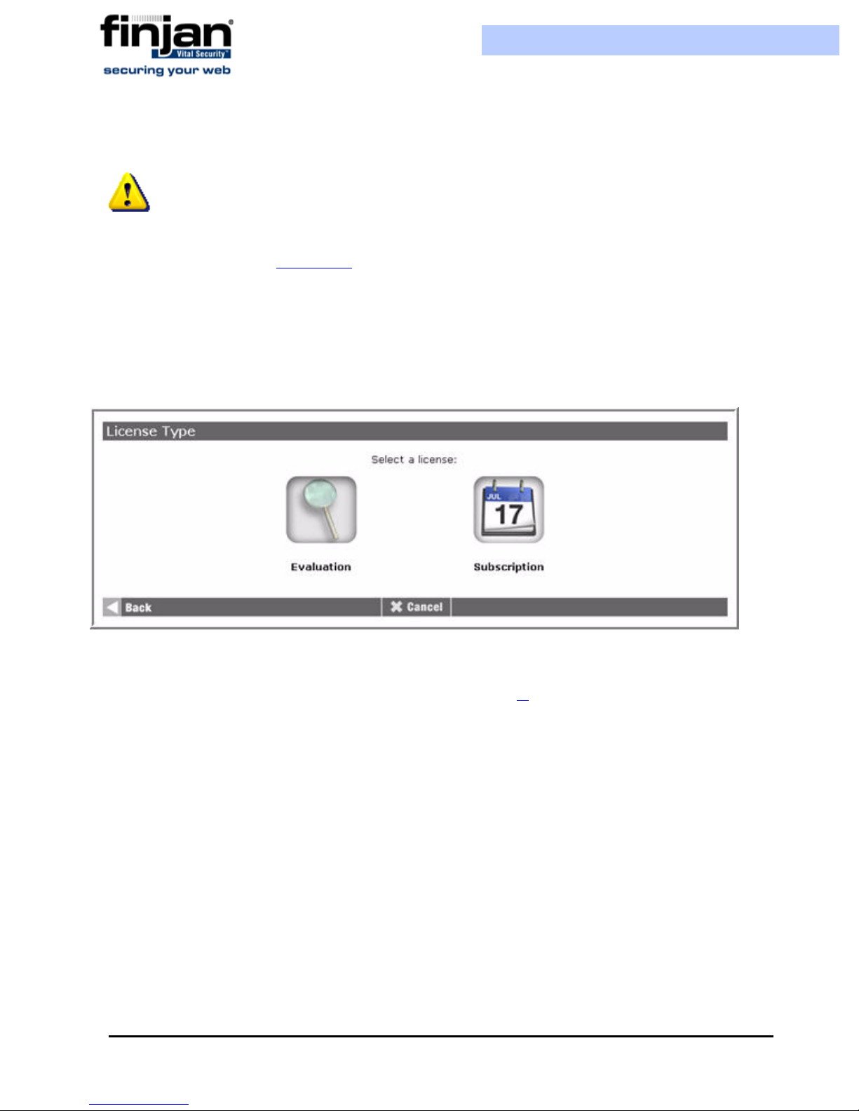
3. The License Type screen is displayed if you have selected Policy Server or All-in-
One server. The Licensing option is disabled for other roles. Click the required
License Type option.
Figure 3-5: License Type
If you selected an Evaluation license, select the required license and security engine
4.
options, and then click Next. (Go straight to step 6.).
Chapter 3 - Getting Started14

Installation and Setup Guide
Figure 3-6: Evaluation License Options
The following table describes the Evaluation License Options:
Field Name Description
Anti-Virus Anti-Virus third party scanning engine
which scans for known viruses (McAfee,
Sophos or Kaspersky depending on your
license)
URL Filtering Third party engine which provides
categorization of Web sites (SurfControl)
Application-Level
Behavior Blocking
Vulnerability Antidote
Anti-Spyware The Anti Spyware engine identifies
5. If you selected a Subscription license, enter the license key that you received from
Finjan’s unique content scanning engine
based on Behavior Profiles (binary or
script)
Unique Finjan engine that scans content
to identify known vulnerabilities
spyware sites and block access to those
sites
either Finjan or your reseller, and then click Next.
Chapter 3 - Getting Started
15

Figure 3-7: Subscription License
The License Details are displayed. Click Next.
6.
Installation and Setup Guide
Figure 3-8: License Details
The Network Interface Used by Policy/Scanning Server screen is displayed . If you
7.
are using an NG-1000 appliance, the Network Interface will look as below.
Figure 3-9: Network Interface NG-1000
Chapter 3 - Getting Started16

Installation and Setup Guide
:
Network Interface for NG-1000
SUPERFORMANCE Appliances
FE0 (eth0): 100MB - Auto-negotiation
enabled. Recommended!
FE1 (eth1): 100MB - Auto-negotiation
enabled
FE2 (eth2): 100MB - Auto-negotiation
enabled
FE3 (eth3): 100MB - Forced 100MB
Full-Duplex
FE4 (eth4): 100MB - Auto-negotiation
enabled
Description
Allows communication at a speed of up to 100MB
with
Auto-Negotiation enabled. Auto-
negotiation enables simple, automatic connection
of devices by taking control of the cable when a
connection is established to a network device that
supports a variety of modes from a variety of
manufacturers. The device is able to automatically
configure the highest performance mode of
interoperation.
Allows communication at a speed of up to 100MB
with
Auto-Negotiation enabled.
Allows communication at a speed of up to 100MB
with Auto-Negotiation enabled.
Allows communication where a speed of up to
100MB is forced and full-duplex, meaning the
transmission of data in two directions
simultaneously.
Allows communication at a speed of up to 100MB
with Auto-Negotiation enabled.
If you are using an appliance from the NG-5000 / NG-6000 series, the screen will
appear as follows:
Chapter 3 - Getting Started
17

Installation and Setup Guide
Figure 3-10: Network Interface (NG-5000/NG-6000)
Network Interfaces for NG-5000 /
NG-6000 Appliances
GE0 (eth0): 1GB - Auto-negotiation
enabled - Recommended!
GE1 (eth1): 1GB - Auto-negotiation
enabled
GE2 (eth2): 1GB - Auto-negotiation
enabled
GE3 (eth3) 1GB - Auto-negotiation
enabled
IMPORTANT: If you want to change the network interface auto negotiation
settings for the NG-5000 /NG-6000, you must do so via the Limited Shell using the
ethconf command. Please refer to Limited Shell
Description
Allows communication at a speed of up to 1GB
with
Auto-Negotiation enabled. Auto-
negotiation enables simple, automatic connection
of devices by taking control of the cable when a
connection is established to a network device that
supports a variety of modes from a variety of
manufacturers. The device is able to
automatically configure the highest performance
mode of interoperation.
Allows communication at a speed of up to 1GB
with
Auto-Negotiation enabled.
Allows communication at a speed of up to 1GB
with
Auto-Negotiation enabled.
Allows communication at a speed of up to 1GB
with
Auto-Negotiation enabled.
Enter the IP address and netmask for the selected interface in the respective fields, and
8.
then click Next. The Routing and Gateway screen is displayed .
Chapter 3 - Getting Started18

Installation and Setup Guide
Figure 3-11: Routing and Gateways
Enter the Gateway IP address and static or local routes as required or leave as is to
9.
enable the default routing and gateway configuration, and then click Next. The
Domain Name Service screen is displayed.
Either define the machine name by filling in the Hostname field or leave as is to
10.
keep the default settings, and then click Next. The Time Settings screen is
displayed.
Chapter 3 - Getting Started
Figure 3-12: Domain Name Service
19

Installation and Setup Guide
Figure 3-13: Time Settings
Ensure that the correct settings have been selected, and then click Next. The Change
11.
Password screen is displayed.
Enter and confirm your new password. Note that changing your password here does
12.
not affect the password in the Management Console. Click Next. The Apply Changes
screen is displayed.
Figure 3-14: Change Password
Chapter 3 - Getting Started20

Installation and Setup Guide
Figure 3-15: Apply Changes
Click Apply in order to apply all of the changes that have been made. The Setup
13.
procedure is complete. Click Next to return to the main Setup Console menu.
2.3.3.1 Configuring the Computer’s IP Address
From the main Setup Console menu, you must then configure your computer’s IP address
and hostname in order for it to be recognized by the Appliance.
To configure the computer’s IP address:
1. Navigate to Advanced Settings
Network Settings Host Addresses. The
Host Addresses screen is displayed.
Figure 3-16: Host Addresses
To add yours and other computers to the system, click Add a new host address.
2.
The Create Host Address screen is displayed.
Chapter 3 - Getting Started
21

Installation and Setup Guide
Figure 3-17: Create Host Address
Enter the IP Address and Hostname of the PC that will work with Vital Security and
3.
click Create. The PC is added to the list. Once the PC is re cognized, the administrator
will have faster performance speed using the Setup Console.
NOTE: If you cannot connect via the interface you have selected (with either the old or
the new IP), temporarily reset FE5 to its default settings via the LCD panel (10.0.5.1,
netmask 255.255.255.0) by navigating to the Reset FE5 IP option, pressing
pressing
Enter again, and then access the Setup Console at https://10.0.5.1:3012
2.3.4 Configuring a Scanning Server
To configure a Scanning Server
1. Click the Initial Setup Wizard icon as appears in Figure 3-3 to begin the setup
procedure, and in the Welcome screen, click Next. The Appliance Role screen is
displayed.
Enter,
Figure 3-18: Appliance Role: Scanning Server
Chapter 3 - Getting Started22

Installation and Setup Guide
2. Select Vital Security Scanning Server from the drop-down menu, and then click
Next. This appliance is used for scanning, while another appliance is providing the
management and reporting services
3. The Network Interface Used by Policy/Scanning Server screen is displayed
(Figure 3-9).
4. Complete the procedure as detailed in (To configure a Policy Server or All in One:
from Step 7 onwards).
5. Configure your computer’s IP address as described in Configuring the Computer’s IP
Address.
3 Update Mechanism
The Update mechanism periodically checks Finjan's Web site and automatically displays
any available updates via the Management Console for the administrator. There are three
categories of updates:
Behavior scanning logic and vulnerability data: These can be configured
automatically. Vital Security behavior profiling data and security processors are
updated automatically from the Finjan site as soon as new Windows vulnerabilities are
discovered. Vulnerability protection typically arrives before viruses that exploit the
vulnerability are released.
Finjan Software is a market leader in malicious mobile code and the Malicious Code
Research Center at Finjan employs dedicated experts who work around the clock to
identify new Windows vulnerabilities and exploits, enabling real day-zero protection.
OS Version updates and new feature add-ons: Automatic downloading from the
Finjan Web site can be enabled/disabled via the Management Console. You will be
notified automatically when updates become available so that you can install them and
keep your system up-to-date.
Third-party security engines: Vital Security incorporates best-of-breed third-party
engines (anti-virus and URL categorization). These applications rely on frequent and
regular updates, and these are downloaded and installed automatically by the autoupdate feature.
3.1 Installing Updates
Updates are installed via the Vital Security Management Console, which runs on the All-inOne appliance or Policy Server at the default HTTPS port (443). It is recommended to
check for updates each time that you use the system, in the event that security and
functional updates have been released either since the product was installed or since the last
check was performed.
Chapter 3 - Getting Started
23

Installation and Setup Guide
3.1.1 Configuring Next Proxy for Updates
If you are connecting your All-in-One appliance or Policy Server to the Internet via a proxy
server, you must configure the proxy in the Proxy Server and Port fields on the Settings
UpdatesUpdates Configuration tab, and then click Apply and Commit Changes to
ensure that the change takes effect.
3.1.2 Configuring the Firewall for Automatic Updates
In order to enable Automatic updates for the NG Appliance Series, the Firewall should be
opened for the Policy Server, using the HTTPS (port 443) protocol in the outgoing direction.
There are two destination URLs:
https://updateNG.finjan.com/remote_update
https://mirror.updateNG.finjan.com/remote_update
The following table details the ports needed for configuring Automatic Updates:
Description Port Number
All in one machine (web traffic ports)
Only HTTP, FTP and HTTPS from
LAN to WAN
Policy Server in LAN Scanner in
DMZ
Additional ports to open from LAN
to DMZ
Manager - transfer of policy
updates, and other updates
Manager – secure transfer of
policy updates, and other updates
Log traffic (from server) 8000
Secure Log traffic 8001
Vital Security Setup Console
(Webmin)
SNMP queries (if enabled) 161 UDP
Additional ports to open from DMZ
and LAN
SNMP trap (if enabled and
configured to send traps to the
SNMP Manager on the LAN)
5222
5224
3012
162 UDP
3.1.3 Offline Updates
Customers who are using the appliance in an isolated network that is not connected to the
Internet, can download any updates from the Finjan update site. These updates can be
manually downloaded and saved onto a removable media (e.g. CD) which should then be
Chapter 3 - Getting Started24

Installation and Setup Guide
connected to the offline computer where you manage the Policy Server. From the
Management Console, you can install the updates using the Import Local Updates option.
This feature requires a special license. Please contact your Finjan representative for further
details.
4 Defining System Device Roles via the Management Console
You can also define and edit system device roles via the Management Console.
To edit system device roles:
1. Log in to the Management Console, open the Settings tab and select Devices. If
you selected Vital Security Policy Server as your appliance role, you have an All
in one preconfigured machine, with a device that is used in the following roles:
Policy Server, Report Server, Log Server, Log Relay and Scanning Server.
If you want to configure an All in One device, change the IP address by selecting
2.
one of the IPs displayed in the Network Roles tree, and then click the Edit Device
icon . The Edit Device dialog box is displayed.
Chapter 3 - Getting Started
Figure 3-19: Network Roles Tree
25

Installation and Setup Guide
Figure 3-20: Edit Device IP Dialog Box
Enter the required IP address, and from the Device Roles list, select All in One.
3.
4. If you want to configure a Policy Server only, delete the existing device, and then
click the Add Device icon. The Add Device dialog box is displayed.
Figure 3-21: Figure 21: Add Device Dialog Box
NOTE: If multiple servers are included on one device, they should be selected together
in the Add Device dialog (using Control on your keyboard). You may not add a server to a
device where the IP address has already been defined
Click OK. The device that you have added now appears in the Network Roles tree.
5.
6. Select the IP address of the device you have added. The device status is displayed.
7. Select the Activate checkbox.
Figure 3-22: Activate checkbox
Chapter 3 - Getting Started26

Installation and Setup Guide
8. Under the Scanning Server device, change the Log Server Interface IP to
127.0.0.1 if not already configured as such.
9. When you have defined all devices in the system or made any changes, click Apply
on the bottom right hand of the screen, and then click Commit Changes.
After defining your devices, Finjan recommends that you change the default password.
To change the default p assword:
1. Select the Settings tab on the Main Navigation bar.
2. From the System tab, select the Password tab. The Change Password dialog box
is displayed.
3. Enter your old and new passwords in the fields shown, and then click Apply.
5 Connecting your V it al Security Appliance NG-8000
The Vital Security Appliance NG-8000 is supplied as one or more separate blades. You
can assign system roles according to your requirements using each blade as a separate
server, or activate more than one service on a single blade.
Each Vital Security appliance is supplied with a default IP address, and can be remotely
accessed for initial setup by any PC in the same subnet. Vital Security uses a secure
(HTTPS) connection to a Web-based interface for remote access.
5.1 Initial Procedures for the Policy Server
The following initial procedure is the same for all the blades irrespective of the intended
network role (except for the Load Balancer).
To configure the Policy Server:
1. Plug in the power cable and switch the appliance on.
2. Configure the network settings of any PC to match those of the appliance (IP
address and subnet mask).
IP address in the same subnet e.g. 10.0.0.101
Subnet mask 255.255.255.0
3. Connect your PC to one of the ports on the Gigabit Ethernet switch in I/O switch
module Bay 1 on the appliance using a network cable.
4. Power up the blades one by one:
Chapter 3 - Getting Started
27

Installation and Setup Guide
To power up the blades one by one:
a Press the Console Select button so that the VGA screen attached to the chassis
displays output from the blade being powered up.
b Press the Power button until the power-up sequence is over. A log in prompt is
displayed.
c Repeat this procedure for each blade.
Figure 3-23: Blade
Open your browser and enter https://10.0.0.1:3012. The Vital Security Set-up Console
5.
login window appears. The Vital Security Set-up Console is a Web-based interface
that enables you to configure initial setup parameters associated with the box itself.
6. Log in to the Vital Security Set-up Console using admin as the username and finjan
as the password, and then click the Advanced Settings icon.
5.2 Initial Procedures for the Vital Security Scanning Server
The following initial procedure is the same for all the blades irrespective of the intended
network role (except for the Load Balancer).
To configure the Vital Security Scanning Server for setup:
1. Plug in the power cable and switch the appliance on.
2. Configure the network settings of any PC to match those of the appliance (IP address
and subnet mask).
IP address in the same subnet e.g. 10.0.0.101
Subnet mask 255.255.255.0
3. Connect your PC to one of the ports on the Gigabit Ethernet switch in I/O switch
module Bay 1 on the appliance using a network cable.
4. Power up the blades one by one:
Chapter 3 - Getting Started28

Installation and Setup Guide
To power up the blades one by one:
a Press the Console Select button so that the VGA screen attached to the
chassis displays output from the blade being powered up.
b Press the Power button until the power-up sequence is over. A login prompt
is displayed.
c Repeat this procedure for each blade.
5. Open your browser and enter https://10.0.0.1:3012. The Vital Security Set-up
Console login window appears. The Setup Console is a Web-based interface that
enables you to configure initial setup parameters associated with the box itself.
6. Log in to the Vital Security Set-up Console using admin as the user name and
finjan as the password.
NOTE: For information on setting up the NG-8000, please contact your Finjan
represetative.
6 Routing Traffic through the Appliance
You can use any of the following proxy setting alternatives, or configure proxy access to be
transparent.
6.1 Configuring Workst ations for Routing T raffic through the
Appliance
Manual Configuration per Individual User
In Internet Explorer, select Tools
Settings and click the Advanced button in the Proxy Servers area. In the Proxy
Settings dialog box, enter the IP address of the Vital Security Scanning Server or Load
Balancer in the HTTP field.
Customized Installation of Internet Explorer
Download the Microsoft tool IAEK6 in order to enable customized installation of
Internet Explorer for all users.
Group Policy Manager
In the Microsoft Active Directory, create a Group Policy Object (GPO) that
configures which proxy to use per machine or user.
Internet Options Connections LAN
Login Scripts
For older legacy systems such as NT4, you can use login scripts to configure the proxy
server.
Chapter 3 - Getting Started
29

Installation and Setup Guide
6.2 Transparent Proxy
Vital Security can be deployed as a transparent HTTP proxy, in conjunction with a third-party
content switch or a layer-4 router in the network. This means that all HTTP traffic is routed, at
packet level, through the content switch to the Vital Security Appliance. End-users are not
aware of this and have the same surfing experience as if they were communicating directly
with the Web server.
When deployed as a transparent proxy, there is no need to configure proxy settings of
individual end-user browsers. However, because of the transparency, the appliance is not able
to perform proxy-level user authentication.
The following diagram illustrates the deployment.
7 Working with HTTP
In order for browsers or other appliances to be protected by Vital Security, the Vital Secuirty
must be configured as the Proxy Server. Working with the Vital Security you can configure
your browser for maximum efficiency (number of requests per second) in Microsoft Internet
Explorer by selecting Tools Internet Options Advanced and selecting both Use HTTP
1.1 and Use HTTP 1.1 through proxy connections.
Figure 3-24: Transparent Proxy
Chapter 3 - Getting Started30

Installation and Setup Guide
7.1 HTTP Proxies
Vital Security can communicate with any RFC-compliant Web proxy.
7.2 Working with Caching Proxies
When a caching proxy is in use, Vital Security can be integrated either upstream or
downstream from the cache proxy in the network.
7.2.1 Downstream
When Vital Security is positioned downstream of the cache proxy, the cached content is
rescanned for every request. This topology clearly works for systems with user/group
policies that differentiate between the sites that the different users/groups may visit, as
every request is submitted to Vital Security and scanned against the relevant policy.
This means that:
Every request is scanned with the latest anti-virus updates, even if the content was
cached before the last update.
Traffic scanned initially by Vital Security is cached and subsequently forwarded again
by the caching proxy in line with additional user requests. Each time this happens, the
content is rescanned by Vital Security. The resulting drain on resources should be
taken into account regarding performance.
Every additional request for cached content is subjected to the policy specific to the
user making the new request. Policy changes will always be implemented because all
content, even if it comes from the cache, is scanned again by Vital Security.
All accesses to cached content are subject to the logging policy, and are potentially
logged by Vital Security.
7.2.2 Upstream
When Vital Security is positioned upstream from the cache, traffic is scanned only once,
and is then cached and forwarded directly to the users. This is optimal for organizations that
use a single policy for all Internet access, and do not apply different policies to different
users/groups. This is not suitable for per user/group policies that differentiate between the
sites visited by users/groups. (In such cases, you may consider working with ICAP.)
This means that:
Because content is only scanned once, there is less drain on resources, leading to
improved performance.
Cached content is not subject to the latest anti-virus updates, nor to policy changes.
Vital Security cannot log accesses to cached content.
Chapter 3 - Getting Started
31

Installation and Setup Guide
7.3 HTTP Authentication
Authentication enables the following:
Ensures that only requests from bona-fide users are handled/processed.
Enables the allocation of different policies to different users and/or groups by matching
authentication data to user identifiers in the system.
Ensures that all logged transactions are attributed to the corresponding user.
In order to implement group, or user-based policies, some form of authentication is clearly
required (e.g. NTLM). This means that a network path must be enabled between Vital
Security and an LDAP server so that it can originate LDAP queries to the LDAP server.
Via the Management Console’s Main Navigation Settings tab, select Defaults HTTP
Authentication in order to configure the Vital Security appliance.
Vital Security can also allow another downstream HTTP proxy to perform the authentication,
in which case:
A downstream proxy needs to be configured to append headers containing user and group
information to requests.
Vital Security should be configured so that it can recognize the specific headers used by
the downstream proxy.
Vital Security can also pass these headers on to the next proxy or alternatively remove
them before submitting the request over the Internet.
8 Working with ICAP
ICAP stands for Internet Content Adaptation Protocol. ICAP is used in conjunction with
caching proxies such as Network Appliance NetCache or BlueCoat Proxy SG. ICAP
configurations typically require significant tuning to maximize the benefits.
For more information about ICAP, go to www.I-cap.org
8.1 Why work with ICAP?
One of the reasons is that if you are working with a caching proxy that supports the ICAP
protocol, you can achieve significant performance benefits from configuring Vital Security as
an ICAP server rather than an HTTP proxy. This is because only the relevant (potentially
dangerous) traffic is submitted for scanning. For example, gif files go straight through without
being scanned.
Chapter 3 - Getting Started32

Installation and Setup Guide
8.2 Vit al Security as an ICAP Server
When deployed in the ICAP environment, the ICAP client typically provides user
credentials and Vital Security does not have to authenticate users.
Figure 3-25: Vital Security as an ICAP Server
8.3 REQMOD – RESPMOD Deployment
As an ICAP Server, Vital Security can provide both REQMOD (Request Modification) and
RESPMOD (Response Modification) services.
The service name for REQMOD is Finjan_REQMOD.
The service name for RESPMOD is Finjan_RESPMOD.
Vital Security can receive both REQMOD and RESPMOD requests.
Here is an example of an ICAP URL for the REQMOD service:
icap://192.168.2.153:1344/Finjan_REQMOD
NOTE: When working with RESPMOD, REQMOD should also be enabled. Although
technically
required to provide the full HTTP transaction context when scanning some types of active
content
Vital Security can also work in REQMOD only, for example, for performing URL filtering,
Vital Security will work in RESPMOD-only mode, the REQMOD service is
.
Chapter 3 - Getting Started
33

Installation and Setup Guide
but in this case, the actual incoming content is not scanned.
Configuration of a Vital Security scanning server as an ICAP server is carried out via the
Management Console.
NOTE: If there is no direct Internet access, in order to perform pre-fetching of
Java classes for Applet scanning, ALL Scanning Servers must have the next proxy
configured. If you are using ICAP, ensure that the NG Appliance Scanning Server
appears on the Access List.
8.4 ICAP Clients
There are a number of ICAP Clients that support Vital Security:
Network Appliance NetCache Series
Blue Coat Proxy SG Series
Finjan Vital Security for SSL
Chapter 3 - Getting Started34

C HAPTER
C
ONFIGURING
This chapter describes the configuration of the following ICAP clients:
Network Appliance NetCache Series (NetApp)
Blue Coat
ICAP C
1 Network Appliance Netcache Series (NetApp)
LIENT S
To configure NetApp via the NetApp web interface:
1. Log in to the NetApp Web interface. The ICAP Setup window is displayed with the
General tab open.
2. Click Setup.
3. Click ICAP
4. Select the Enable Version 1.0 option.
ICAP 1.0 in the left hand pane.
Chapter 4 - Configuring ICAP Clients 35

Installation and Setup Guide
Figure 4-1: ICAP Setup - General
Open the Service Farms tab.
5.
6. Press the New Service Farm button to create a new ICAP Service.
To configure an ICAP Service Farm:
1. To set a REQMOD service, ensure that the following conditions are met:
In the Vectoring Point field, select REQMOD_PRECACHE.
In the Services field set the service URL:
icap://[Vital Security’s IP]:[ICAP port]/Finjan_REQMOD on
2. To set a RESPMOD service, ensure that the following conditions are met:
In the Vectoring Point field select RESPMODE_PRECACHE
In the Services field set the service URL:
icap://[Vital Security’s IP]:[ICAP port]/Finjan_RESPMOD on
Several services can be defined in Services and load-balanced by NetApp.
Chapter 4 - Configuring ICAP Clients36

Installation and Setup Guide
Figure 4-2: New ICAP Service Farm
Once the services have been configured in the Service Farms, Access Control List
3.
rules should be defined to include these services.
Chapter 4 - Configuring ICAP Clients
37

Installation and Setup Guide
With every ICAP settings change, NetApp sends an OPTIONS request to the relevant ICAP
Service.
2 Blue Coat
Finjan is a certified Blue Coat partner.
To configure Blue Coat via Vital Security:
1. In the Vital Security Management Console, select Settings
2. In the Devices screen, select the Scanning Server with which you are working, and
then select ICAP.
Figure 4-3: Access Control Lists
Devices.
Chapter 4 - Configuring ICAP Clients38

Installation and Setup Guide
Figure 4-4: ICAP Protocol: Blue Coat Configuration
In the Weights for ICAP Resource Allocation section, click Add. A drop-down
3.
menu is displayed.
4. Select Blue Coat from the Type drop-down list.
5. Enter the IP address of the ICAP client, enter a weight of 100, and click Add.
6. In the ICAP Listening Port section, enter the IP address of the Scanning Server,
click Apply, and then click Commit Changes on the top right of the screen.
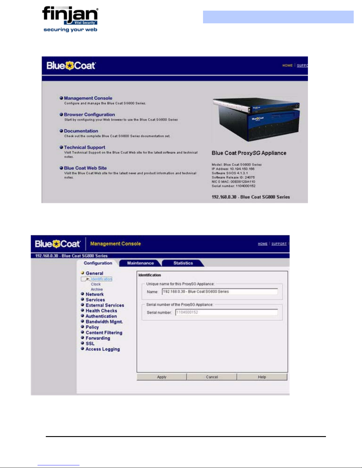
To configure Blue Coat via the Blue Coat Web interface
1. Log in to the Blue Coat web interface.
Chapter 4 - Configuring ICAP Clients
39
Installation and Setup Guide
Figure 4-5: Blue Caot Main Screen
Navigate to the Management Console.
2.
Figure 4-6: Blue Coat Management Console
Chapter 4 - Configuring ICAP Clients40

Installation and Setup Guide
NOTE: If, at any time during the session, the Java Plug-in Security Warning appears,
select Grant this session to continue.
To define REQMOD (Request Modification) Service.
1. From the Blue Coat Management Console, select External Services
ICAP. The
ICAP Services screen is displayed on the right.
2. At the bottom of the ICAP Services screen, click New. The Add List Item dialog
box is displayed.
3. Enter a name and click OK. For instance, Reqmod. The External Services window
is displayed again with the name you have selected.
Click Edit. The Edit ICAP Services dialog box is displayed.
4.
Chapter 4 - Configuring ICAP Clients
Figure 4-7: Blue Coat ICAP Services
41

Installation and Setup Guide
Figure 4-8: Edit ICAP Services
Chapter 4 - Configuring ICAP Clients42

Installation and Setup Guide
The following table describes the field data to be entered:
Field Name Field Data to be entered
ICAP Version Select 1.0 from the dropdown list
Server Type Enter the following: icap://<scanner IP
(ICAP server)>:<scanner port
(default=1344)>/Finjan_REQMOD. For
example, icap://192.168.90.10:1344/
Finjan_REQMOD
Method Supported Click the request modification radio
button.
1. If your Vital Security scanner is up and running, then press the Sense Settings
button and then OK. A confirmation message appears; click OK again.
(If, on the other hand, your Vital Security scanner is not yet up and running, then
click OK only to continue. In this case, you should return to this dialog box later on
when Vital Security is up and running in order to select Sense Settings)
2. In the Edit ICAP Services box, select the Authenticated User checkbox and then
click OK.
3. Click Apply in the ICAP Services screen to complete the configuration.
To activate the REQMOD Service:
1. In the Blue Coat Management Console, select Policy
Visual Policy Manager.
The Visual Policy Manager is displayed.
Chapter 4 - Configuring ICAP Clients
43

Installation and Setup Guide
Figure 4-9: Visual Policy Manager Launch
Click Launch and the Visual Policy Manager dialog box is displayed.
2.
Figure 4-10: Visual Policy Manager Dialog Box
From the Main Menu Bar, select Policy Add Web Content Layer, and the Add
3.
New Layer dialog box is displayed.
Chapter 4 - Configuring ICAP Clients44

Installation and Setup Guide
Figure 4-11: Add New Layer Dialog Box
Add in the required name and click OK. The Visual Policy Manager is displayed
4.
with a new Web Access Layer.
Figure 4-12: Web Access Layer Added
In the Action column, right-click on Use Default Caching, and then select Set. The
5.
Set Action Object dialog is displayed.
Chapter 4 - Configuring ICAP Clients
45

Installation and Setup Guide
Figure 4-13: Set Action Object
Scroll down and select ICAPRequestService1.
6.
7. Click Edit. The Edit ICAP Request Service Object window is displayed.
Chapter 4 - Configuring ICAP Clients46

Installation and Setup Guide
Figure 4-14: Edit ICAP Request Service Object
Select the Use ICAP Request Service checkbox.
8.
9. From the drop-down list, select the REQMOD you have defined, and click OK.
10.Go back to the Set Action Object dialog box, and click OK.
11.Click the Install Policy button in the Visual Policy Manager.
To define RESPMOD (Response Modification) Service
This is carried out using the same steps as for REQMOD with the following differences:
1. In the Edit ICAP Service dialog box (Figure 4-14)
The Service URL should be:
icap//<scanner IP (ICAP server)>:<scanner port (default=1344)>/
Finjan_RESPMOD.
For example, icap://192.168.90.10:1344/Finjan_RESPMOD
The Method Supported should be response modification instead of
request.
2. In the Set Action Object dialog box (Figure 4-13), select ICAPResponse1 instead
of ICAPRequestService1. This opens the Edit ICAP Response Service Object
dialog box.
Chapter 4 - Configuring ICAP Clients
47

Installation and Setup Guide
3. In the Edit ICAP Response Service Object (Figure 4-14), select Use ICAP
response service and from the drop-down list, select the RESPMOD service that you
have defined, and then click OK.
Chapter 4 - Configuring ICAP Clients48

C HAPTER
A
DVANCED
S
1 Introduction to Setup Console Advanced Settings
After using the Initial Setup Wizard to configure the appliance, the Advanced Settings can
be used to improve and manage the functionality of the appliance. Each appliance will have
different configuration needs. Therefore, after completing the Initial Setup Wizard, the
Advanced Settings enable you to access each configuration option as required, and
configure it to match the system needs.
ETTINGS
NOTE: Please refer to the Initial Setup Wizard for detailed information about initial
configuration of the appliance.
The Advanced Settings options enable you to define the role the appliance takes, the type of
license the appliance works under, the security, access and time settings, and also carry out
routine maintenance operations.
For further in-depth analysis and diagnostics of the system, the Network Settings option
(within the Advanced Settings) is used to define how the network works, and how the
appliance communicates with the network.
2 Configuring Advanced Settings
From the Setup Selection Screen, select Advanced Settings. The Advanced Settings
screen is displayed.
Chapter 5 - Advanced Settings 49

Installation and Setup Guide
Figure 5-1: Advanced Settings
The Advanced Settings screen contains the following options:
Appliance Roles: Selecting this option opens a wizard which takes you through the steps
for selecting a role and defining a Network Interface to be used as the primary server
connection for the appliance.
Licensing: This option is used to select the correct License Type to apply to the
appliance.
Custom Commands: This option is used to enable SNMP Monitoring and Support
Access on the appliance, provides repair commands for the Policy Server database and
the configuration repository, and enables changing the SNMP community string, and the
Management Console IP address and HTTPS Listening Port.
Time Settings: This option is used to set the System and/or Hardware Time, and offers
the option of synchronizing the time settings with an external Time Server
Network Settings: This option provides further configuration options, allowing you to
carry out diagnostics and to run in-depth checks on the appliance.
Change Password: Use this option to change the password for access to the Setup
Console.
Restart Role: This is used if there are functionality problems with the appliance software.
Reboot/Shutdown Appliance: The Reboot command is used if there are operational
problems with the appliance. The Shutdown command is used when it is necessary to
switch off and remove the appliance from any power supply.
Chapter 5 - Advanced Settings50
Installation and Setup Guide
Active/Standby Policy Server: This option allows you to switch from the current
Active Policy Server to the Standby Policy Server.
NOTE: Any configuration changes made to the appliance are valid only for that
particular appliance, and not for any other appliance connected to the network. Each
appliance must be configured individually.
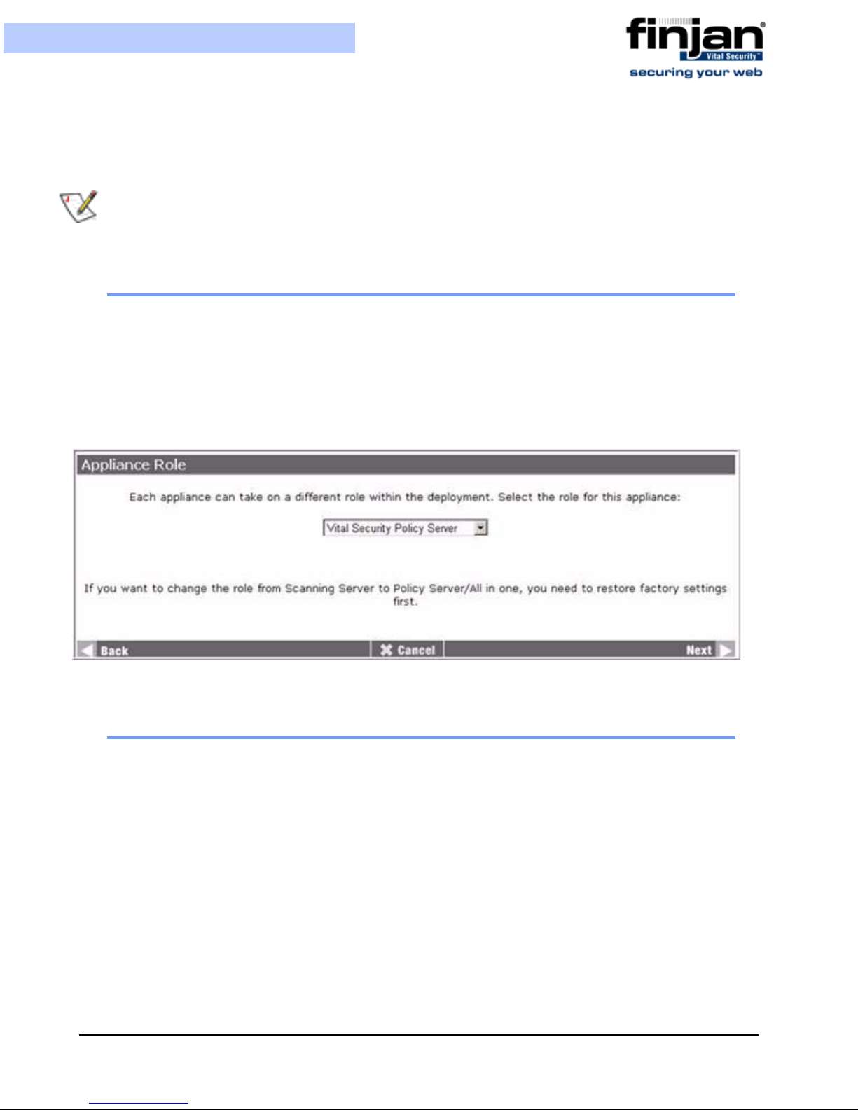
2.1 Appliance Role
The Appliance Role screen is used to change the role of the Appliance. This screen is the
same one as appears in the Initial Setup Wizard. Selecting the Policy Server, Scanning
Server or All in One – redirects you to the Network Interface Used by Policy/Scanning
Server screen. Only Network Interfaces that are selected to be activated at boot time will
appear in the selection menu. Choose the required Network Interface, and click Next and
then Apply to apply any changes you make.
2.2 Licensing
The License Type screen is used to select the license. This screen is the same one as
appears in the Initial Setup Wizard.
Chapter 5 - Advanced Settings
Figure 5-2: Appliance Role
51

Installation and Setup Guide
Figure 5-3: License Type
2.3 Custom Commands
Selecting Custom Commands displays the following screen:
The following sections describe the options available within the Custom Commands screen.
Figure 5-4: Custom Commands
Chapter 5 - Advanced Settings52

Installation and Setup Guide
2.3.1 Change SNMP Monitoring Options
This will enable an SNMP client to access network and resource utilization information via
SNMP. The traps listed in the Management Console will only work if SNMP Monitoring
has been enabled here.
NOTE: When accessing the Custom Commands screen, the current status of SNMP
Monitoring is not displayed.
To enable SNMP Monitoring:
1. In the Change SNMP Monitoring Options section, select Yes to enable SNMP
monitoring.
Figure 5-5: Change SNMP Monitoring Options
Click Change SNMP Monitoring Options to apply the changes. The Execute
2.
Command window is displayed confirming SNMP is enabled.
Figure 5-6: SNMP Monitoring Enabled
Click Back to return to the Custom Commands window.
3.
Chapter 5 - Advanced Settings
53

Installation and Setup Guide
2.3.2 Change Support Access Option
This will allow privileged users, e.g. the Finjan Support Team, to access the appliance to
provide support, or run checks or reports on the machine.
NOTE: It is advisable to turn the Support Access option off once the support activity has
ended.
To enable Support Access to the Management Console
1. In the Change Support Access Options section, select Yes to enable support access
to the appliance. You can also enable resetting the Support User Password from this
screen.
Figure 5-7: Change Support Access to Appliance
Click Change Support Access Options to apply the changes. The Execute Command
2.
window is displayed confirming Support Access is enabled.
Figure 5-8: Support Access Enabled
NOTE: There is no back button in this command window, which provides an end to the
command. The server receives the instruction, and restarts itself. To return to the Custom
Commands window, click the Back button in your web browser.
Chapter 5 - Advanced Settings54

Installation and Setup Guide
2.3.3 Repair Configuration Repository
This option checks if the configuration repository is corrupted. If corruption is detected, the
repository is then repaired.
To rep air the Configuration Repository:
1. Click Repair Configuration Repistory:
Figure 5-9: Repair Configuration Repository
The Execute Command window is displayed. Click Back to return to the Custom
2.
Commands window.
NOTE: The Configuration Repository stores the settings, configured in the Vital
Security Management Console, required for an appliance to function correctly in its
specified role.
2.3.4 Repair Policy Server Dat abase
This option backs up and restores the Policy Server database.
To rep air the Policy Server database:
1. Click Repair Policy Server database to back up and restore the Policy Server
database.
Figure 5-10: Repair Policy Server database
The Execute Command window is displayed. Click Back to return to the Custom
2.
Commands window.
2.3.5 SNMP Community String
The SNMP community string is used to enable access to the SNMP protocol.
Chapter 5 - Advanced Settings
55

Installation and Setup Guide
To change the SNMP Community String:
1. In the SNMP Community String section, enter the new SNMP community string.
NOTE: The appliance has a default password so that access to the SNMP proto col is
automatically available.
Figure 5-11: SNMP Community String
Click SNMP Community String to apply the change. The Execute Command
2.
window is displayed confirming the SNMP community string has been changed
successfully.
3. In the Execute Command window, click Back to return to the Custom Command
window.
2.3.6 Management Console IP Address/Port
Changes to the Management Console IP address/port can be made where there is a need to
limit access to the Management Console across the network, or define different levels of
access to the Management Console.
To change the Management Console IP address/port:
1. In the Management Console IP Address field, enter the new IP address, for example
10.0.5.1, or enter * to retain current IP addresses configured on the appliance.
Figure 5-12: Management Console IP address/port
In the Management HTTPS listening port field, enter the required port number.
2.
NOTE: The appliance has a default HTTPS listening port to enable immediate
communication through the appliance on initial connection.
3. Click Change Management Console IP address/port. The Execute Command
window is displayed confirming the Management Console IP address/port have been
Chapter 5 - Advanced Settings56

Installation and Setup Guide
changed successfully. Access to the Management Console through your browser is
now through the specified IP address and port: https://10.0.5.1:1234.
4. In the Execute Command window, click Back to return to the Custom Commands
window.
2.3.7 Collect Specific Log Information
This feature enables collecting just the log files (without the database or other heavy data).
This may take up to 5 minutes during which log data will be collected from the machine and
compressed into a downloadable tar.gz file.
Figure 5-13: Collect Specific Log Information
2.4 Time Settings
To configure the Time Settings:
1. In the Advanced Settings screen, click Time Settings. The System Time window
is displayed.
Chapter 5 - Advanced Settings
57

Installation and Setup Guide
In the Time Zone section, set the Time Zone to your local time zone.
2.
3. You can set either the Hardware Time or System Time and match one to the other. To
set the Hardware Time, enter your local time in the Hardware Time section.
4. To match the System Time to the Hardware Time, click Set System Time to
Hardware Time.
Figure 5-14: System Time
Chapter 5 - Advanced Settings58

Installation and Setup Guide
5. Repeat steps 3-4 to set System Time and match the Hardware Time to the System
Time, and then click Save.
6. For more accurate time checking you can synchronize your System Time settings
with an external Time Server. In the Timeserver hostnames or addresses field,
enter the required hostname or IP address.
NOTE: Synchronizing your time settings with an external Time Server is strongly
recommended, especially when working with distributed topologies.
7. Select the Set hardware time too checkbox to also synchronize the hardware time.
8. To synchronize to the Time Server settings randomly, select No in the
Synchronize on schedule section.
9. To synchronize on schedule, select Yes in the Synchronize on schedule section,
and select the required time schedule in the scheduling options below.
10.Click Sync and Apply. The screen refreshes with the scheduling configuration.
2.5 Network Settings
Clicking Network Settings in the Advance Settings screen, displays the Advanced
Network Settings screen.
Chapter 5 - Advanced Settings
59

Installation and Setup Guide
Figure 5-15: Advanced Network Settings
The Advanced Network Settings options are as follows:
The Network Interfaces option is used to enable the appliance to communicate with other
computers on the network.
The Routing and Gateways option is used to define the paths that the system should take
to reach certain hosts and networks.
The DNS Client option is used for converting a hostname into an IP address, and vice-
versa.
The Host Addresses option is used to configure and match IP addresses with hostnames
locally, without the use of a DNS server.
This is used when changes made in different configuration options need to be applied
simultaneously, for example, changes made to Network Interfaces may affect the Routing
and Gateway settings, so it is preferable to make the necessary changes to the Routing and
Gateway settings, and then apply changes to both the options simultaneously.
The Network Diagnostics options are used to check network connectivity and
communications with other hosts within the network.
Chapter 5 - Advanced Settings60

Installation and Setup Guide
2.5.1 Network Interfaces
Clicking Network Interfaces in the Advance Network Settings screen, displays the
Network Interface screen.
In the Network Interfaces screen, the Interfaces Activated at Boot Time list displays the
interfaces that are configured permanently on the system. These can be optionally brought
up at boot. The Interfaces Active Now list displays interfaces that are currently up.
To edit a Bootup Interface:
1. In the Advanced Network Settings screen, click Network Interfaces. The
Network Interfaces screen is displayed.
2. In the Interfaces Activated at Boot Time section of the screen, select the required
interface to open the Edit Bootup Interface window.
Chapter 5 - Advanced Settings
Figure 5-16: Network Interfaces
61

Installation and Setup Guide
Figure 5-17: Edit Bootup Interface
Enter the IP address, or select From DHCP for it to be dynamically assigned, or if
3.
your system supports it, select From BOOTP.
4. Enter the Netmask and Broadcast address if required.
NOTE: Netmask configuration is essential when using static IP.
5. In Activate at boot?, select Yes or No as required. If Yes is selected, the interface
will appear in the Interfaces Active Now section of the Network Interfaces screen
after applying the network settings, or after system restart, as well as in the Interfaces
Activated at Boot Time section.
6. To save the changes and apply them at a later stage, click Save.
7. To activate the Boot interface immediately, click Save and Apply.
To edit the configuration of an Active Interface:
1. In the Network Interfaces screen, select the required interface from the Interfaces
Active Now list. The Edit Active Interface screen is displayed.
Chapter 5 - Advanced Settings62

Installation and Setup Guide
Figure 5-18: Edit Active Interface
Configure the Active Interface parameters as follows:
2.
IP Address – A unique Internet Protocol address for the given Network Interface.
When you change the IP address here, you
Console. Please refer to Defining System Device Roles via the Management Console
for more information.
Netmask - The Netmask address is used to communicate with computers outside of the
network
Broadcast - The Broadcast address is used to enable communication with several
computers within one network
MTU - Defines the maximum size of the packets sent from your appliance onto the
network Any packets larger than the size set here are divided into smaller packets.
Status – The Network Interface may be brought up or down (temporarly enabled/
disabled).
Hardware address – The MAC address. Generally this does not have to be changed.
3. Click Save to save the configuration changes.
2.5.2 Routing and Gateways
MUST change it in the Management
Clicking Routing and Gateways in the Advanced Network Settings screen, displays the
Routing and Gateways screen.
Chapter 5 - Advanced Settings
63

Installation and Setup Guide
Figure 5-19: Routing and Gateways
To configure Routing and Gateways:
1. In Default Router, select Gateway and enter the IP address in the Gateway field.
2. In the Device field, select the required interface from the drop-down menu.
3. Configure Static routes or Local routes as required, or leave as is to enable the
default routing and gateway configuration.
Static routes – configured to enable traffic to choose another route to some known host
or network, rather than going through the default route.
Local routes – set up routing to additional IP networks on connected LANs
4. Click Save.
2.5.3 DNS Client
Clicking DNS Client in the Advance Network Settings screen, displays the DNS Client
screen. DNS Cache enables caching of Domain names and addresses which reduces network
traffic to and from the DNS Server and hence speeds up system performance.
The following behavior is supported by the DNS Cache mechanism. It performs a DNS health
check which is carried out on all configured DNS servers through the DNS protocol. If there is
a DNS failure, then there is automatic failover between servers. The DNS cache is persistent
which means that it can survive an appliance reboot. Caching is enabled also for multi-IP hosts
if they are provided by the configured DNS Servers through the DNS Protocol.
When the DNS cache is enabled and the user changes the DNS servers settings there is no need
to run restart role.
Chapter 5 - Advanced Settings64

Installation and Setup Guide
Figure 5-20: DNS Client
To configure a DNS Client:
1. In the Hostname field, enter the name of the PC.
2. In Resolution order, from the various options, select the required resolution order.
3. Select Update hostname in host addresses if changed if required.
4. In the DNS servers fields, enter the IP address of up to three servers. If the first is
not available, the system will try the second, and then the third.
5. In the Search domains field, enter any domain names that should be automatically
appended to any search results, and then select Listed, or leave the Search
domains field empty, and select None.
6. In the DNS Cache field, select On or Off to enable or disable DNS Cache. It is
automatically enabled when clicking Apply in the initial Setup Wizard in the Setup
Console.
7. Click Flush DNS Cache to "flush" (i.e., empty) the cache, and restart it.
8. Click Save to save any changes made.
NOTE: When enabling/disabling DNS Cache (On/Off), you need to run Restart Role for
the settings to take effect.
2.5.4 Host Addresses
Clicking Host Addresses in the Advanced Network Settings screen, displays the Host
Addresses screen.
Chapter 5 - Advanced Settings
65

Installation and Setup Guide
Figure 5-21: Host Addresses
To add a Host address:
1. Click on the Add a new host address. The Create Host Address window is
displayed.
In the IP Address field, enter the IP address.
2.
3. In the Hostnames field, enter all possible hostnames which can be matched to the IP
address, and click Create. The IP address and hostnames are added to the Host
Addresses list.
2.5.5 Apply Network Settings
Click on the Apply Network Settings icon in the Advanced Network Settings window to
apply any configuration changes that need to be applied simultaneously.
2.5.6 Network Diagnostics
Clicking Network Diagnostics in the Advanced Network Settings screen, displays the
Network Diagnostics screen.
Figure 5-22: Create Host Address
Chapter 5 - Advanced Settings66

Installation and Setup Guide
Figure 5-23: Network Diagnostics
The Network Diagnostic options are as follows:
The Ping option is used to test whether a particular host is operating properly and is
communicating on the network with the testing ged host.
The Traceroute option is used to determine the route packets take over the network to
reach a particular host.
This option is used to check the process of resolving IP addresses with Hostnames.
This option gives a snapshot of the active connections on the appliance, connections
that are waiting, or listening.
The Tcpdump option is used to display all communication on the system at a certain
time. There are no time limits or size limits on the information displayed.
2.5.6.1 Ping
To use the ping option:
1. In the Network Diagnostics screen, click Ping. The Ping screen is displayed.
Chapter 5 - Advanced Settings
67

Installation and Setup Guide
Figure 5-24: Ping
In the Hostname field, enter the required hostname.
2.
3. Configure any other relevant parameters, and click Ping It! The Ping report is
displayed.
Chapter 5 - Advanced Settings68

Installation and Setup Guide
Figure 5-25: Ping Report
2.5.6.2 Traceroute
To use Traceroute:
1. In the Network Diagnostics screen, click Traceroute. The Traceroute screen is
displayed.
Chapter 5 - Advanced Settings
69
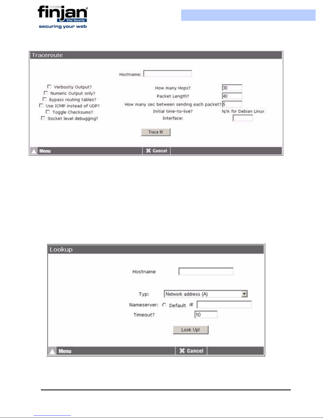
Figure 5-26: Traceroute
Installation and Setup Guide
In the Hostname field, enter the hostname.
2.
3. Configure any other required parameters, and click Trace It! The Traceroute report is
displayed.
2.5.6.3 Lookup
To use Lookup:
1. In the Network Diagnostics screen, click Lookup. The Lookup screen is displayed.
In the Hostname field, enter the required hostname.
2.
Figure 5-27: Lookup
Chapter 5 - Advanced Settings70

Installation and Setup Guide
3. Configure any other required parameters. The Nameserver refers to the DNS
Server IP address that you can enter in the text box displayed.
If you select the radio button next to Default than whichever DNS servers are
defined in the Advanced Settings Network Settings DNS Client will be
used.
4. C
lick Look Up! The Lookup report is displayed.
2.5.6.4 Netstat
To use Net stat:
In the Network Diagnostics screen, click Netstat. The Netstat screen is displayed.
Chapter 5 - Advanced Settings
71

Installation and Setup Guide
Figure 5-28: Netstat
Chapter 5 - Advanced Settings72

Installation and Setup Guide
2.5.6.5 Tcpdump
To use the Tcpdump option:
1. In the Network Diagnostics screen, click Tcpdump. The Tcpdump screen is
displayed.
Figure 5-29: Tcpdump
In Active Network Interfaces, select the required interface.
2.
3. In Ports, enter the port number, or leave empty. Entering a port number sets limits
on the amount of traffic captures.
4. Click Start. The capture begins.
5. Click Stop to stop the current capture.
6. Click Download to download the file if required.
2.6 Change Password
The Change Password screen is the same as that of the Setup Console Wizard (Figure 3-
14).
NOTE: Changing your password for the Setup Console does not affect the password for
the Management Console.
Chapter 5 - Advanced Settings
73

Installation and Setup Guide
2.7 Restart Role
To rest art the appliance role:
1. In the Advanced Settings screen, click Restart Role to display the Restart Role
window.
Figure 5-30: Restart Role
Click Next. The Finished screen is displayed.
2.
2.8 Reboot/Shutdown Appliance
To reboot or shut down the appliance:
1. In the Advanced Settings screen, click Reboot/Shutdown Appliance to display the
Reboot/Shutdown Appliance window.
Figure 5-31: Reboot/Shutdown Appliance
Click Reboot System to reboot the system.
2.
Chapter 5 - Advanced Settings74
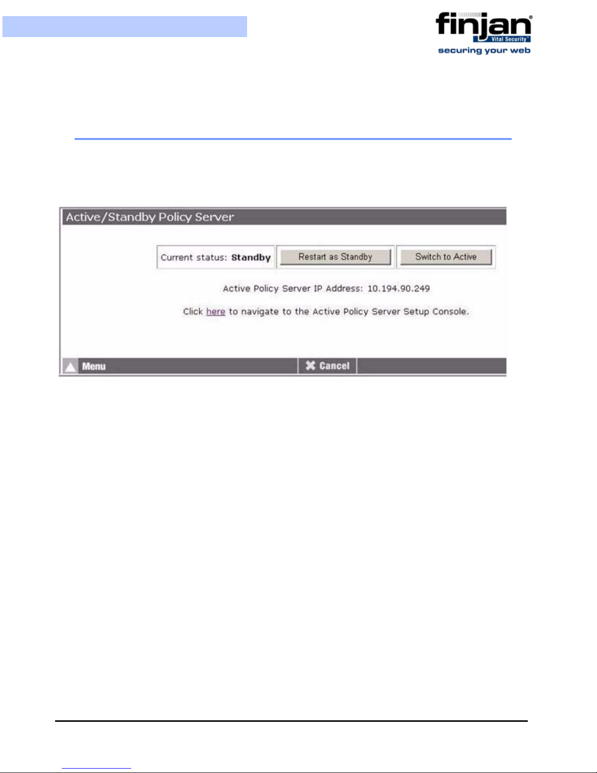
Installation and Setup Guide
3. Click Shutdown System to shut down the system.
2.9 Active/St andby Policy Server
This screen displays the Policy Server’s status: Active or Standby. The High Availability
feature containing the Active or Standby Policy Servers must be initially enabled from the
Management Console in order for this screen to appear.
Figure 5-32: Active/Standby Policy Server
To restart the role of a Policy Server, whether as Active or Passive, you can click on the
Restart as button to force a restart of the Active/Standby Policy Server.
You can choose to switch the Policy Server from Active to Standby or vice versa by
clicking the Switch to button.
The IP address of the other Policy Server that you defined in the Management Console
(Settings Devices Policy Server High Availability Policy Server
configuration) will be displayed here. It will be displayed either as the Standby Policy
Server Address or as the Active Policy Server Address depending on what the status is of
this Policy Server.
Click on the link to be redirected to the other Policy Server Setup Console (again – this will
be displayed as either active or standby – depending on the status).
For more information on this feature, please refer to the High Availability Policy Server
Technical Brief.
Chapter 5 - Advanced Settings
75


A PPENDIX
L
IMITED
The Limited Shell feature enables monitoring and viewing the appliance’s configuration
via a serial or SSH connection. Configuration changes cannot be made using this feature.
An administrator can log in to the Limited Shell from a remote machine using an SSH
client or by connecting to the appliance serial or vga port. The password to the shell
(command line) is the same as for the Setup Console.
If the current installation was performed through an update (on top of a previous version)
then the Setup Console password should be set explicitly in order to reset the limited shell
password. Otherwise, access will be denied.
S
HELL
SSH access is enabled only if support access is enabled via the Setup Console. To do this,
go to the Setup Console Custom Command screen and click on Yes to enable support
access to appliance. Then click on Change Support Access Options.
No other root user can log in directly to the system. Privileged access (root level) is
achieved only after logging in as Super Administrator from the Limited Shell.
A timeout mechanism is activated such that idle connections are disconnected after 5
minutes.
After you log in to the Limited Shell, enter help to see a list of commands that the shell user
can run and their use.
The following monitoring commands are available:
Command Description
arp Displays arp table
date Displays current date and time
df Displays disk usage
disable_al Disables access list
enable_al Enables Access List
ifconfig Displays NIC configuration and
statistics
ip2name (ip2name ip) Resolves ip to hostname
iptraf Interactive IP LAN Monitor
last Displays last login
Appendix A - Limited Shell 77

Installation and Setup Guide
Command Description
name2ip (name2ip name) Resolves hostname to ip
netstat Displays network statistics
Ping (ping IP/Hostname) Sends ICMP ECHO_REQUEST
to network hosts
sh_db_size Shows database file size
showroute Displays routing table
supersh Provides access to privileged
shell
top Displays linux tasks
uptime Displays uptime
vmstat Reports information about
system. CTRL-C to stop
w Shows who is logged on and
what they are doing
ha_ps_enable Define a Standby Policy Server
ethconf Change network interface
Appendix A - Limited Shell78

A PPENDIX
I
NST ALLATION
In order to install 8.4.0 and higher, the update can be performed using an Installation CD.
This effectively removes the need to perform Restore Factory Settings.
To inst all this Release using the Installation CD on NG-6000/NG-5000:
1. Attach a CD drive, or a bootable USB flash device and USB-keyboard and VGA
Monitor, to the appliance.
CD
2. When the Finjan screen appears, type yes to continue with the process.
3. Let the installation run – it will take approximately 10 minutes. The Appliance
LCD will indicate that the Vital Security has not been installed yet.
4. Set up the configuration as required via the Setup Console
NOTE: Currently, the built-in CD-Rom device in the NG-6000 cannot be used.
To inst all this Release using the Installation CD on NG-1000:
1. Attach a CD drive, or a bootable USB flash device and USB-keyboard and VGA
Monitor, to the appliance.
2. Check in the BIOS that it is set to Boot from CD/Flash Device using USB2.0.
a Navigate to Advanced BIOS features and press Enter.
b Using the arrow keys and the Page Up/Page Down keys, select the required
device to boot from (e.g., USB-CDROM).
c To change the USB to 2.0, navigate backwards using the Escape key and
select Integrated Peripherals.
d Select Enabled on the USB2.0 Controller.
Initial Settings.
3. Change the third boot device from HDD-1 to HDD-0.
4. Press F10 to exit and save configuration.
5. When the Finjan screen appears, type yes to continue with the process.
Appendix B - Installation CD 79

Installation and Setup Guide
6. Let the installation run – it will take approximately 10 minutes. The Appliance LCD
will indicate that the Vital Security has not been installed yet.
7. Set up the configuration as required via the Setup Console
To inst all this Release using the Installation CD on NG-8000:
1. Attach a CD drive to the blade.
2. When the Finjan screen appears, type yes to continue with the process.
3. Choose the first scsi disk available.
4. Let the installation run – it will take approximately 20 minutes.
5. Set up the configuration as required via the Setup Console
Initial Settings.
Initial Settings.
Appendix B - Installation CD80
 Loading...