

Page 1
VKC 11 SERIES
Sealless, Non-Metallic Vertical Pumps
Installation and Maintenance Instructions
Pat. No. 5,708,313
ASSEMBLY
WARNING: Magnetic field hazard. This pump contains powerful
rare earth magnets. When the pump is disassembled (not
connected to a motor) and the magnets are exposed, these
magnets produce powerful magnetic fields. Individuals with
cardiac pacemakers, implanted defibrillators, other electronic
medical devices, metallic prosthetic heart valves, internal wound
clips (from surgery),metallic prosthetic devices or sickle cell
anemia must not handle or be in the proximity of the magnets
cntained inside the pump. Consult a health care provider for
specific recommendations before working with this pump.
PUMPS WITH MOTORS
1. No assembly required. Simply unpack the pump and motor
and examine for any signs of shipping damage. If damage is
detected, save the packaging and notify the carrier immediately.
2. Ensure that lock rings are securely snapped in place and did
not loosen during shipment.
3. Proceed to the “Installation” section of these instructions.
PUMPS WITHOUT MOTORS:
(56C/143-145TC FRAME)
1. Unpack the pump and any supplied accessories and examine for damage. If damage is detected, save the packaging
and notify the carrier immediately.
2. Create a hole if required for discharge piping in the optional
mounting plate (item 9) at desired location.
3. Prepare to install the motor on the pump. Carefully place the
motor on the fan cover on a suitable, level work surface.
4. Install key into motor shaft key slot. Align the keyway slot on
coupling half (item 8) and slide it into motor shaft. Set coupling half flush with the end of the motor shaft and tighten
both set screws with 1/8” Allen wrench to 70 in-lbs. (7.9 N-m).
5. Insert the coupling insert (item 9) into the coupling half on the
motor. Carefully slide motor adapter (item 8) end of the column assembly over the motor shaft until both coupling halves
are completely seated in the coupling insert. Make sure rabbet
(step) on the motor is firmly seated into motor adapter.
CAUTION: Pump assembly may be top heavy.
6. Rotate the pump and mounting plate to the desired orientation. Align the holes in the mounting plate and the motor
adapter with the holes in the motor face. Secure the mounting plate and motor adapter to the motor using (4) washers,
lock washers and 3/8" bolts (items 5,6,7) from the hardware
package (if metric frame, use (4) 3/8" hex nuts (item 33).
7. Ensure that lock rings are securely snapped in place and did
not loosen during shipment.
8. Install the pump into the system according to the installation instructions.
METRIC FRAME
1. Unpack the pump and any supplied accessories and examine for damage. If damage is detected, save the packaging
and notify the carrier immediately.
2. Make a hole if required for discharge piping in the optional
mounting plate (item 9) at desired location.
3. Prepare to install the motor on the pump. Carefully place the
motor on the fan cover on a suitable, level work surface.
4. Install key into motor shaft key slot. Align the keyway slot on
coupling half (item 8) and slide it into motor shaft. Set coupling half flush with the end of the motor shaft and tighten
both set screws with 1/8” Allen wrench to 70 in-lbs. (7.9 N-m).
5. Install the metric motor adapter flange (item 2) on the motor
with (4) socket head cap screws (item 4). Use lock washers
(item 3) on 80 frame motors only (90 frame motors do not
require any washers). One side of the adapter has a B stamped
on it and this side faces the motor on an 80 frame. The other
side has an A stamped on it (with hex nut recessed bolt
holes). This side (side A) is for 90 frame motors.
6. Proceed to steps 5-8 in section “Pumps without Motors 56C/143-145TC Frame.”
INSTALLATION
The VKC Series is a versatile pump designed to be operated in a
variety of mounting configurations. The pump can be mounted
either inside or outside of a tank or sump.
Note: Drawings for illustration only. Pumps need to be properly
supported when installed.
Figure 1Figure 1
Figure 1
Figure 1Figure 1
11
1
11
Page 2

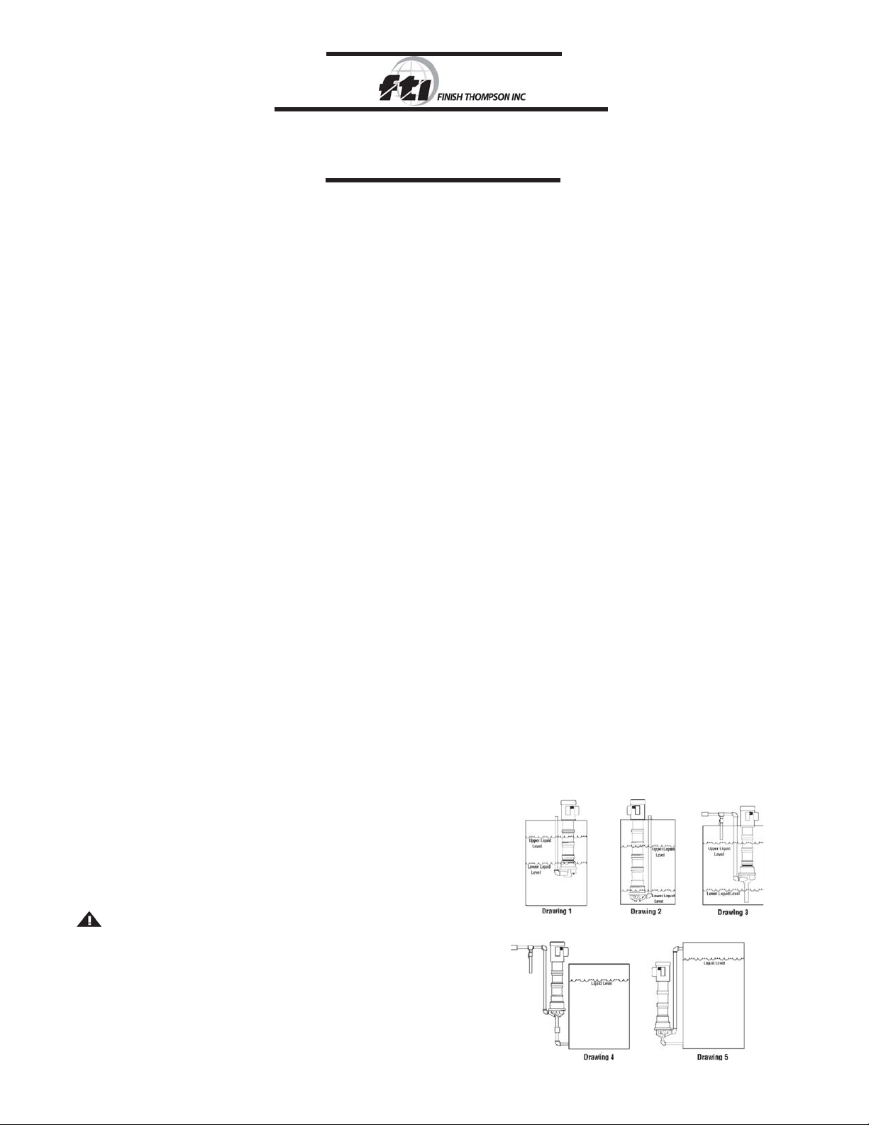
Drawing 1 shows drawing of pump mounted inside a tank with suction
off the bottom of the tank and level fluctuating from near top of pump
column to close to the bottom of the pump.
Drawing 2 shows drawing of pump suction near tank bottom and level
fluctuating between the top and bottom of the tank.
Drawing 3 shows drawing of pump with suction extension and the level
fluctuating between start-up level and low level.
Drawing 4 shows drawing of pump mounted outside the tank.
Drawing 5 shows drawing of pump mounted outside the tank with the
motor below the liquid level.
MOUNTING
A mounting plate is recommended for in tank installations. If required, use a hole saw to cut holes in desired location for piping.
Support and securely fasten the mounting plate on all four sides
if possible or on two sides if mounted in a corner. Drill holes in the
mounting plate at the desired location for bolting to the tank.
A drip cover may be installed on top of the motor if desired.
Mount pump in desired configuration. Securely fasten mounting
plate if used. Motor feet may also be used for mounting.
PIPING
1. Support piping near the pump to eliminate any strain on the
pump casings. Do not use suction or discharge piping to support the pump.
2. Do not place the pump suction directly on the bottom of the
tank. Keep the pump suction at least one pipe diameter off the
bottom.
3. A suction extension tube of up to nine feet in length can be
added.
4. To minimize head loss from friction:
Increase pipe size by 1 diameter.
Use minimal number of pipe bends.
5. If a check valve is installed in the discharge piping, an air bleed
must be installed in the discharge line to prevent air lock. This
allows air trapped in the pump internals to be removed on initial
start-up. See drawings 3 and 4 in Figure 1.
6. Maintain a flooded suction. Use a foot valve if necessary.
7. Ensure that the piping does not leak and suction is not prone
to clogging. Use a strainer if necessary on the suction.
8. If flexible hose is preferred, use reinforced hose rated for the
proper temperature and pressure. This helps avoid collapse or
kinks.
9. Install valves a minimum of 10 pipe diameters from the
pump.
CAUTION: To stop the pump if prime is lost, use one of
the following: (1) pressure switch on the discharge or
(2) motor minder to monitor motor current.
ELECTRICAL
Install the motor according to NEC requirements and local electrical codes. Motor should have an overload protection circuit.
Important - To verify correct motor rotation:
1. Install the pump into the system.
2. Fully open the suction and discharge valves.
3. Allow fluid to flow into the pump. Do not allow the pump to
run dry (PTFE and ceramic bushings cannot be run dry without damage to pump components).
4. Jog the (allow it to run for 1-2 seconds) and observe rotation of the motor fan. Correct rotation is clockwise as viewed
from the motor fan. Refer to directional arrow on pump if
needed.
NOTE: A pump running backwards will pump but at a greatly
reduced flow and pressure.
OPERATION
1. Completely open discharge valve. On pumps equipped with
a discharge check valve, open air bleed valve on initial startup.
2. Start the pump and check liquid flow. If there is no flow, see
the Troubleshooting section.
3. Adjust the flow rate and pressure by regulating the discharge
valve.
MOTOR REPLACEMENT- REMOVAL
1. Place the pump on the motor fan with the suction pointing up.
2. Note orientation of the mounting plate (if used) to the electrical box
for reassembly purposes.
3. Remove the four bolts and washers (items 5, 6, and 7) and pull the
pump up off the motor face.
4. If metric motor - remove the four socket head cap screws and
washer (items 3 and 4), and remove the metric motor adapter flange
(item 2) from the motor face.
5. Remove the coupling insert, loosen the setscrews and remove the
coupling half from the motor shaft.
MOTOR REPLACEMENT - INSTALLATION
1. Slide the coupling half (item 8) onto the motor shaft until it
is flush with the bottom of the motor shaft. Install the motor
shaft key and tighten both setscrews with a 1/8” Allen wrench
to 70 in.-lbs. (7.9 N-m).
2. For metric frame, install the metric motor adapter flange (item
2) on the motor with (4) socket head cap screws (item 4).
Use lock washers (item 3) on 80 frame motors only (90 frame
motors do not require any washers). One side of the adapter
(stamped with a “B”) fits 80 frame motors, and the other side
(with hex nut recessed bolt holes and stamped “A”) is for 90
frame motors.
3. Place the coupling insert completely onto the pump shaft
coupling half. Install the pump onto the motor face making
sure the coupling half on the motor shaft engages completely into the insert.
4. Orientate the mounting plate (if one is used) with the electrical box (as noted during disassembly). Align the bolt holes
and install the four bolts with washers (items 5, 6, and 7)
through the mounting plate into the motor face. Be sure the
pump seats correctly onto the motor face and tighten all of
the bolts.
5. Lay the pump on its side and spin the motor fan to verify
there is no rubbing, binding or misalignment.
22
2
22
Page 3

GENERAL NOTES
1. Do not pump liquids containing metal fines.
2. If magnets decouple, stop the pump immediately. The rare earth
magnets used in this pump are more resistant to demagnetization, but operating the pump with the magnets decoupled will
eventually weaken the magnets.
3. Plastic pumps will expand and contract with temperature so the
plastic column sections.
4. An information plate is attached to the mounting plate or motor
adapter section. The first line is the model number, and the
second line is the serial number. See Figure 2.
VKC SUMP
Figure 2Figure 2
Figure 2
Figure 2Figure 2
5. Due to the hermetically sealed design, the pump will displace
liquid as follows:
Cantilevered = approximately 1 gallon (3.78 liters)
Sumps = add approximately 1 quart (.95 liters) per column
section.
E.G. 24” sump = 1 1/2 gallons (4.73 liters)
Figure 3Figure 3
Figure 3
Figure 3Figure 3
33
3
33
Page 4

44
4
44
Page 5

*Contact Distributor
55
5
55
Page 6

NO DISCHARGE
1. Pump not primed.
2. Air lock in pump.
3. Discharge head too high.
4. Closed valve.
5. Viscosity or specific gravity too high (magnets uncoupled).
INSUFFICIENT DISCHARGE
1. Discharge head higher than anticipated.
2. Clogged suction line, foot valve or crimp in hose.
3. Foot valve too small.
4. Foot valve or suction opening not submerged enough.
5. Incorrect pump rotation.
INSUFFICIENT PRESSURE
1. Air or gasses in liquid.
2. Impeller diameter too small.
3. Discharge head higher than anticipated.
4. Incorrect pump rotation.
LOSS OF PRIME
1. Leaking discharge line.
2. Suction lift too high or insufficient NPSHA. Should be 2 feet
above NPSHR.
3. Air or gasses in liquid.
4. Foreign matter in impeller.
5. Leaking valve.
6. Malfunctioning level sensor or control.
EXCESSIVE POWER CONSUMPTION
1. System head is lower than ratings. Pumps too much liquid.
2. Specific gravity or viscosity of liquid being pumped is too
high or higher than defined in application.
3. Binding pump parts.
VIBRATION/NOISE
1. Excess bearing wear.
2. Drive magnet uncoupled.
3. Loose magnet.
4. Pump cavitating.
5. Motor or piping not properly secured.
6. Foreign object in impeller.
7. Set screws on motor shaft coupling loose.
WARRANTYTROUBLESHOOTING
Finish Thompson, Inc (manufacturer) warrants this product to
be free of defects in materials and workmanship for a period of
one year from date of purchase by original purchaser. If a
warranted defect, which is determined by manufacturer’s
inspection, occurs within this period, it will be repaired or replaced
at the manufacturer’s option, provided (1) the product is submitted
with proof of purchase date and (2) transportation charges are
prepaid to the manufacturer. Liability under this warranty is
expressly limited to repairing or replacing the product or parts
thereof and is in lieu of any other warranties, either expressed or
implied. This warranty does apply only to normal wear of the
product or components. This warranty does not apply to products
or parts broken due to, in whole or in part, accident, overload,
abuse, chemical attack, tampering, or alteration. The manufacturer
accepts no responsibility for product damage or personal injuries
sustained when the product is modified in any way. If this
warranty does not apply, the purchaser shall bear all cost for
labor, material and transportation.
Manufacturer shall not be liable for incidental or consequential
damages including, but not limited to, process down time,
transportation costs, costs associated with replacement or
substitution products, labor costs, product installation or
removal costs, or loss of profit. In any and all events,
manufacturer’s liability shall not exceed the purchase price of
the product and/or accessories.
Call our toll free Technical Service Hot Line, 1-800-888-3743, if you
have any questions regarding product operation or repair.
ORDERING SPARE PARTS
Spare parts can be ordered from your local distributor. Always
refer to pump model number to avoid error.
OTHER FINISH THOMPSON PRODUCTS
Drum Transfer Pumps capable of flows to 40 gpm, discharge head
to 80 feet and viscosities to 100,000 cP.
Portable Mixers for turbine mixing and blending in 316 SS.
Centrifugal Pumps in polypropylene, PVDF, 316 SS, and cast
iron (ANSI dimensional) are offered in magnetic drive sealless or
mechanical seal models.
Toll Free Technical Service 800-888-3743
Part Number J103243, Rev. 7
Literature I.D. Number FT98-702H, 0622/06
66
6
66
 Loading...