

Page 1
Page 2

Table of Contents
Model/Serial Number ........................................................................................................................ 3
Important Notice ............................................................................................................................... 3
Chemical Reaction Disclaimer .......................................................................................................... 3
Safety Precautions ........................................................................................................................... 3-4
SP11/15 Capabilities ........................................................................................................................ 4
Priming Times ................................................................................................................................... 5
Section 1 - Assembly ........................................................................................................................ 6
Section II - Installation ...................................................................................................................... 8
Section III - Start-up and Operation .................................................................................................. 9
Section IV - Shut Down .................................................................................................................... 10
Section V - Disassembly ................................................................................................................... 10
Section VI - Clamp Rin Replacement and Reassembly ................................................................... 14
Part Number Explanation ................................................................................................................. 17
SP11/15 Parts Diagram .................................................................................................................... 18
SP11/15 Spare Parts List .................................................................................................................19-23
Section VII - Troubleshooting ........................................................................................................... 24
Section VIII - Warranty...................................................................................................................... 25
NOTE: Maintenance videos are now available on line at www.nishthompson.com
When you see this icon in the following instructions, click on it to view
the video.
FTI Contacts:
Tech Service: 1-800-888-3743; techservice@nishthompson.com
Order Fax: 1-814-459-3460 or 1-814-455-8518
Sales: 1-800-934-9384 (toll free U.S. and Canada; 1-814-455-4478)
Page 3

Model Number and Serial Number
Record the model number and serial number below for future reference. This is important information when ordering replacement parts or when technical assistance is required. The numbers are found on a label located on the motor adapter.
MODEL NUMBER = ________________________
SERIAL NUMBER = ________________________
IMPORTANT NOTICE
U.S. Export Administration Regulations, pursuant to ECCN 2B350, prohibit the export or reexport to certain enumerated countries of
sealless centrifugal pumps in which all wetted materials are constructed from fluoropolymers without first applying for and obtaining
a license from the U.S. Bureau of Industry and Security (BIS). This affects all Finish Thompson magnetic-drive pumps constructed from
PVDF or lined with ETFE. Please contact the BIS (www.bis.doc.gov) or Finish Thompson with questions regarding the Regulations or a
list of the countries to which they apply.
Chemical Reaction Disclaimer
The user must exercise primary responsibility in selecting the product’s materials of construction, which are compatible
with the uid(s) that come(s) in contact with the product. The user may consult Finish Thompson, Inc. (manufacturer)
and a manufacturer’s representative/distributor agent to seek a recommendation of the product’s material of construction
that offers the optimum available chemical compatibility.
However neither manufacturer nor agent shall be liable for product damage or failure, injuries, or any other damage or
loss arising out of a reaction, interaction or any chemical effect that occurs between the materials of the product’s con-
struction and uids that come into contact with the product’s components.
Safety Precautions
WARNING: READ THIS MANUAL COMPLETELY BEFORE INSTALLING AND OPERATING THIS UNIT. FAIL-
URE TO FOLLOW THESE PRECAUTIONS CAN RESULT IN SERIOUS INJURY OR DEATH.
WARNING: Magnetic eld hazard. This pump contains powerful magnets. Exposed magnets (pump not connected
to motor) produce powerful magnetic elds. Individuals with cardiac pacemakers, implanted debrillators, other elec-
tronic medical devices, metallic prosthetic heart valves, internal wound clips (from surgery), metallic prosthetic devices or
sickle cell anemia must not handle or be in the proximity of the magnets contained inside the pump. Consult a health care
provider for specic recommendations before working with this pump.
WARNING: Magnetic force hazard. This pump should only be disassembled and assembled using the recommend-
ed procedures. The magnetic attraction is powerful enough to rapidly pull the motor end and the wet end together. Do not
place ngers between the mating surfaces of the motor and wet ends to avoid injuries. Keep the drive magnet and impeller
assembly away from metal chips or particles, items with magnetic stripes like credit cards and magnetic computer media
such as oppy discs and hard drives.
WARNING: Not Recommended for Pumping Flammable or Combustible Liquids. During the priming process
the internal pump atmosphere can become very dangerous should the pump fail to prime and overheat.
If using the SP Series to pump non-ammable or non-combustible liquids in a hazardous area, you must follow these
guidelines:
1. Select the Ns (non-sparking) bronze bump ring option. The non-sparking ring is pressed into the clamp ring or motor
adapter and prevents sparking should the motor bearings fail and the outer mag drive assembly runs out of round.
2. Select an FTI explosionproof motor or provide your own.
WARNING: Hot surfaces. This pump is capable of handling liquids with temperatures as high as 220º F (104º C).
This may cause the outer areas of the pump to become hot as well and could cause burns.
WARNING: Rotating Parts. This pump has components that rotate while in operation. Follow local safety standards
for locking out the motor from the power supply during maintenance or service.
3
Page 4

WARNING: Chemical Hazard. This pump is used for transferring many types of potentially dangerous chemicals.
Always wear protective clothing, eye protection and follow standard safety procedures when handling corrosive or personally harmful materials. Proper procedures should be followed for draining and decontaminating the pump before disassembly and inspection of the pump. There may be small quantities of chemicals present during inspection.
WARNING: Never run pump at less than minimum ow or with the discharge valve closed. This could lead to pump
failure.
WARNING: The pump and associated components are heavy. Failure to properly support the pump during lifting and
movement could result in serious injury or damage to the pump and components.
CAUTION: This pump should never be started without the 1 US gallon (3.8 liters) of priming uid in the housing. If
the pump has a PTFE, ceramic or silicon carbide bushing, IT CANNOT BE RUN DRY WITHOUT CAUSING DAM-
AGE TO THE PUMP. However, the pump can operate without liquid in the housing if the pump has a carbon bushing.
The exact length of time the pump can run dry with a carbon bushing varies with operating conditions and environment.
CAUTION: Never start or operate with a closed suction valve.
WARNING: Operation without priming or against a closed discharge valve can result in high temperatures that can
result in injury or damage to pump components.
CAUTION: Always provide adequate NPSHa (net positive suction head available). It is recommended to provide at
least 2 feet (61 cm) above the NPSHr (net positive suction head required).
CAUTION: If pump is used on variable speed drive, do not exceed the frequency for which the pump was designed
(for example, if the pump is a 50 Hz model, do not exceed 50 Hz).
SP11/15 Capabilities
Maximum Working Pressure: 90 psi (6.2 bar)
Maximum Temperature: Polypropylene: 180º F (82º C); PVDF: 220º F (104º C)
NOTE: Maximum temperature is application dependent. Consult a chemical resistance guide or the chemical
manufacturer for chemical compatibility and temperature limits.
Maximum Lift: 25 feet (7.6 meters)
NOTE: Lift determined on fresh, cold water with 1 1/2” Schedule 40 pipe. Specic gravity affects lift capability.
Divide 25 feet (7.6 meters) by the specic gravity to determine equivalent maximum lift.
Solids: Maximum particle size is 100 microns for slurries and 1/64” (.4 mm) for occasional solids. Maximum hardness
is 80 HS. Maximum concentration is 10% by weight. If solids are being pumped, it is recommended that the pump have
either ceramic or for best results, silicon carbide components. Pumping solids may lead to increased wear.
NOTE: While the pump is capable of being used in sump applications, it is NOT a trash pump. Care must be taken
to ensure that debris and foreign objects do not enter the pump or damage may result. A 1-1/2” strainer basket with
1/8” (32mm) perforations is suggested. Regular strainer basket maintenance is required to prevent plugging and
decrease in NPSHa so as not to starve and damage the pump.
Minimum Allowable Flow Rate
Do not allow the ow rate to drop below the minimum ow rate listed in the chart below.
Model 3450 rpm 1725 rpm 2900 rpm 1450 rpm
SP11 4 gpm (.9 m3/hr) 2 gpm (.5 m3/hr) .76 m3/hr (3.4 gpm) .38 m3/hr (1.7 gpm)
SP15 5 gpm (1.1 m
3
/hr) 2.5 gpm (.6 m3/hr) .95 m3/hr (4.2 gpm) .48 m3/hr (2 gpm)
Maximum Noise Level: 78 dBA (pump only)
Maximum Allowable Motor Power
Do not exceed the maximum power rating for the pump coupling.
Standard coupling for the SP11 is 6-pole; standard coupling for the SP15 is 8-pole.
• 6-pole coupling = 2 horsepower (1.5 kW)
4
Page 5
SP11 / 15 Priming Times
3450 RPM; 60-Hz
0
5
10
15
20
25
30
0 1 2 3 4 5 6
Time (minutes)
Lift (ft)
0
1
2
3
4
5
6
7
8
9
Lift (m)
SP15
SP11
SP11 / 15 Priming Times
2900 RPM; 50-Hz
0
1
2
3
4
5
6
7
8
9
0 1 2 3 4 5
Time (minutes)
Lift (m)
SP15
SP11
Note: Times shown are guidelines only and may vary depending on system and piping setup
• 8-pole coupling = 3 horsepower (2.2 kW)
• 10-pole coupling = 5 horsepower (4 kW)
Priming Liquid Volume
Initial lling (or relling after maintenance) of the pump housing requires 1 US gallon (3.8 liters) of liquid.
5
Page 6
Unpacking and Inspection
Unpack the pump and examine for any signs of shipping damage. If damage is detected, save the packaging
and notify the carrier immediately.
Section I - Assembly
Tools Required:
Metric socket or wrench set, 9/16” socket or wrench, 8 mm Allen wrench, and 3/16” Allen wrench (NEMA motors
only) and pliers (for ll/drain plugs).
Pumps with Motors
Proceed to “Installation” Section
Pumps Without Motors
NOTE: 184TC and 100/112 frame motors must have motor feet.
1. Remove the pump, drive magnet assembly and hardware package from the carton.
CAUTION: Keep away from metallic particles, tools and electronics.
Drive magnets MUST be free of metal chips.
WARNING: Keep the drive magnet away from the open end of the motor adapter and barrier.
Strong magnetic attraction could allow the drive hub to enter the motor adapter resulting in injury
or damage.
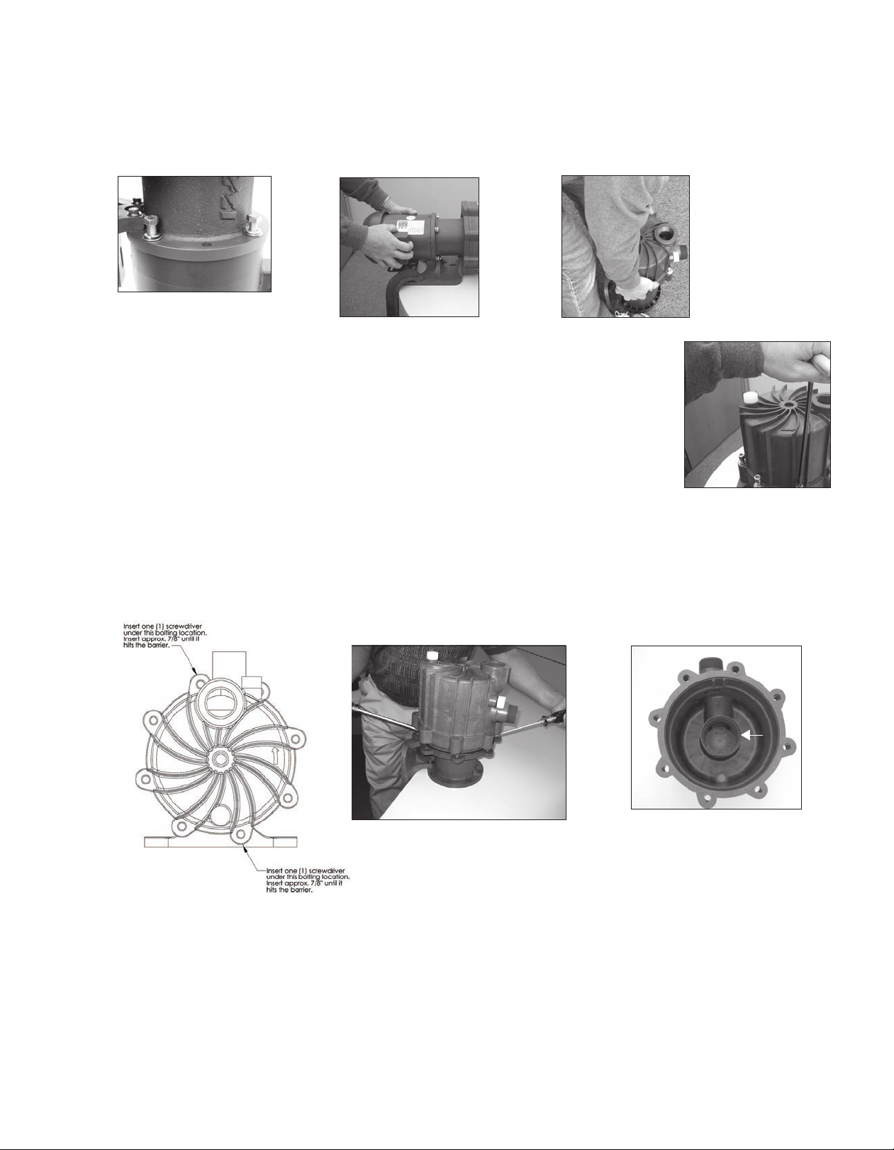
2. Place motor on the fan end. For 56C/145TC and
B5 frame motors go to step 4. See gure 1.
3. For 184 NEMA and IEC motors only - Install the motor
adapter ange (item 14) on the motor face using bolts,
lock washers and at washers (items 25, 26, 27). See gure 2.
NOTE: Apply anti-seize compound on threads of the bolts.
Torque bolts to the following:
• 80 frame (M6) = 90 in-lb (10.2 N-m)
• 90/100/112 frame (M8) = 130 in-lb (14.7 N-m)
• 184 NEMA (1/2”) = 480 in-lb (54.3 N-m)
4. Coat the motor shaft with anti-seize compound. Insert key
supplied with motor into keyway on motor shaft. See gure 3.
NOTE: Make sure the motor shaft is clean and free of burrs.
The outer drive is precision machined and has a bore tolerance of +.0005/-0 inch.
5. Slide the outer drive magnet assembly (item 13) onto the motor
shaft until the motor shaft contacts the snap ring in the bore
of the drive. Figures 4 and 5.
Figure 1
Figure 2
Figure 3
6. Secure the drive on the motor shaft.
Figure 4 Figure 5
6
Page 7
WARNING: Be careful, magnets will try to attract tools.
Metric Motors: Secure the drive to the motor shaft using bolt, lock washer and at washer (items 19, 20, 21).
Thread the bolt into the end of the motor shaft (while holding the outer drive to prevent it from turning). See
gure 6.
Tighten the bolt to the following:
* 80 frame (M6) = 90 in-lb (10.2 N-m)
* 90 frame (M8) = 130 in-lb (14.7 N-m)
* 100/112 frame (M10) = 240 in-lb (27.1 N-m)
Figure 6 - IEC
NEMA Motors: Install set screws (item 13A) into threaded holes on
the side of the outer drive magnet assembly. Using a 3/16” Allen wrench,
tighten to 228 in-lbs (25.8 N-m). See gure 7.
7. Install the pump end on the motor/drive magnet assembly. With the motor
facing upright, align the pump feet so that the motor feet and pump feet
are on the same side.
Tip the pump end at an angle (discharge is approximately 45º) so that it is
Figure 7 - NEMA
just touching the edge of the outer drive magnet assembly. See gure 8.
Carefully lower the pump onto the drive magnet assembly by tipping discharge
forward to 90º and dropping straight down. The last 3-4 inches (8-10 cm) before
the pump reaches the motor will have STRONG magnetic attraction between the
pump and outer drive magnet assembly.
8. Secure the pump to the motor with (4) 3/8” bolts, lock washers
and at washers (items 22, 23. 24). See gures 9 and 10.
Figure 9
Figure 10
NOTE: Apply anti-seize compound on the threads of the bolts.
NOTE: B5 motors will require customer supplied hardware.
9. Rotate the motor fan to ensure that there is no binding in the pump.
Figure 8
10. Install the plastic foot (item 15) to the motor adapter (item 12D). Use the longer M6 bolts, lock washers and at
washers (items 28A, 29, and 30) for the front bolt holes towards the clamp ring. See gure 40 on page 15.
11. Use the shorter M6 bolts, lock washers, and at washers (items 28, 29, and 30 on page 15) for the rear bolt holes
towards the motor face. Note: Nuts (item 31) are glued into the rear of the motor adapter to help with the installation
of the rear bolts. Make sure the nuts are still in place. See gure 41 on page 15. Tighten bolts to 5 ft-lbs (6.8 N-m).
7
Page 8
Section II - Installation
Mounting -
Pump foot should be securely
fastened to a solid foundation. If
the pump was received with plastic
shipping shims, it is possible to
use these as additional support
for the motor feet (though not
required).
NOTE: B5 pumps with
100/112 frame do not include a
pump foot.
CAUTION: The NPSH
available to the pump must be
greater than the NPSH required.
The amount of lift, frictional pipe
loss and vapor pressure must be
calculated into the application.
NPSH available should be 2 feet
(.6 meters) greater than NPSH
required.
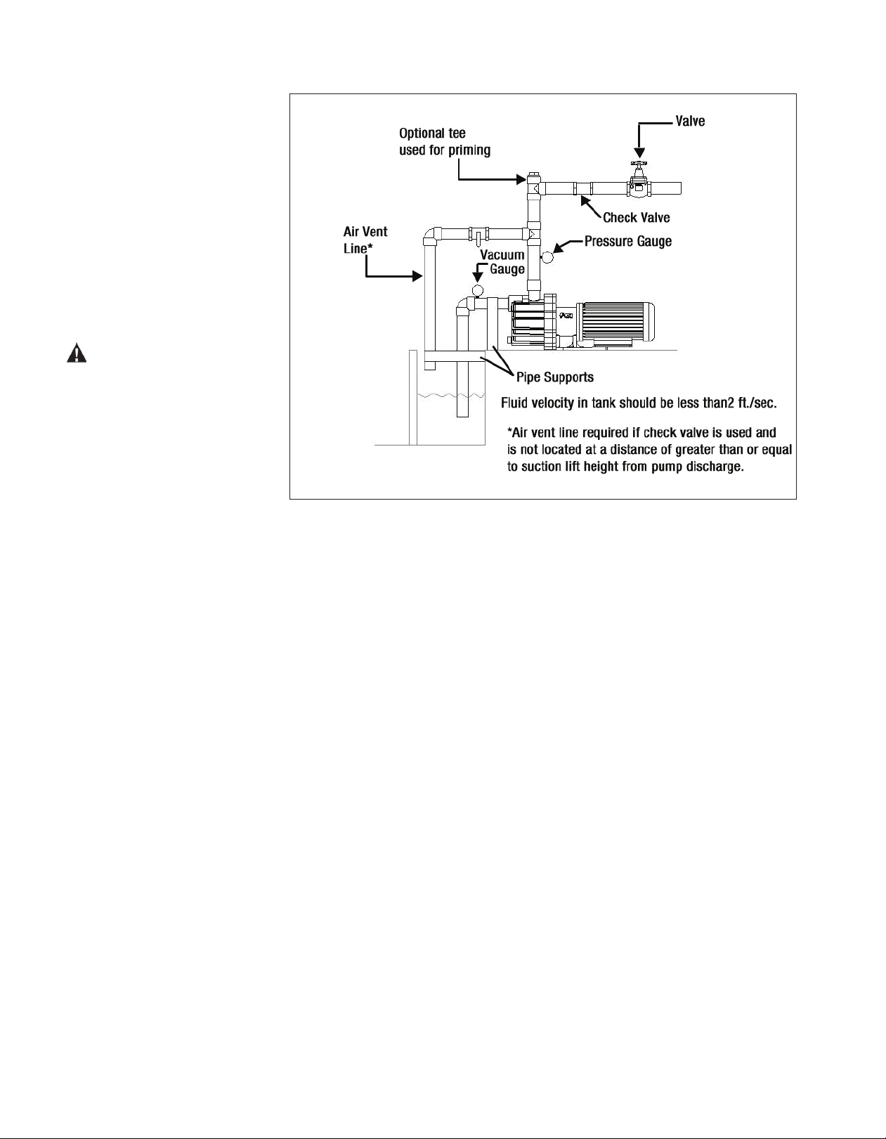
SP Piping Diagram
• Total suction lift including pipe friction loss and corrections for specic gravity must not exceed 25 feet (7.6 meters).
NOTE: Maximum suction lift is reduced by 1.13 feet (.34 meters) for every 1,000 feet (304 meters) of altitude.
• Install the pump as close to the suction source as possible.
• SP Series pumps are designed to operate in a horizontal position only with discharge on the top.
• SP Series pumps self-priming capability is due to its ability to create a vacuum in the suction piping. The suction
piping MUST be airtight at ttings and connections.
• Support the piping independently near the pump to eliminate any strain on the pump casing. In addition, the piping
should be aligned to avoid placing stress on the pump casing.
• The suction side of the pump should be as straight and short as possible to minimize pipe friction.
• The suction line should not have any high spots. This can create air pockets that can reduce pump performance.
The suction piping should be level or slope slightly upward to the pump.
• The suction pipe should be 1 1/2” (38 mm). Larger suction piping will affect priming ability. Smaller piping affects
NPSH available and pump performance.
• Provide for adequate suction submergence. Excessive submergence will reduce pump performance.
• The end of the pipe should be at least 3” (7.6 cm) above the bottom of the suction tank.
• If a strainer is used, it must be periodically cleaned to prevent restriction.
• It is recommended that a vacuum/pressure gage be installed in the suction piping.
• For faster priming on installations with high lift, a foot valve is recommended.
• Check and control valves (if used) should be installed on the discharge line. The control valve is used for regulat-
ing ow. Isolation valves on the suction and discharge are used to make the pump accessible for maintenance. The
check valve helps protect the pump against damage from water hammer. This is particularly important when the
static discharge head is high.
8
Page 9

• NOTE: If a check valve is used in the discharge line, it must be placed at a distance at least equal to the maximum
suction lift from the pump. If this cannot be done, an air vent must be provided in the discharge line.
• If exible hose is preferred over pipe, use a reinforced hose rated for the proper temperature, pressure and is chemi-
cally resistant against the uid being pumped.
• The suction valve must be completely open to avoid restricting the suction ow.
• When installing pumps with anges, we recommend use of low seating stress gaskets such as Gore-Tex or Gylon
(expanded PTFE).
• It is advisable to install a ush system in the piping to allow the pump to be ushed before the pump is removed
from service.
NOTE: The pump is provided with a 1/2” BSP drain in the impeller housing.
• A “tee” can be installed in the discharge piping as an alternative location for lling the housing with uid before
pump operation.
• “Filling” is dened as lling the housing with 1 US gallon (3.8 liters) of liquid
• “Priming” is dened as evacuating all the air from the suction piping/pump and replacing it with uid.
Motor/Electrical
Install the motor according to NEC requirements and local electrical codes. The motor should have an overload protection circuit.
Wire the motor for clockwise rotation when facing the fan end of the motor.
CAUTION: Do not operate the pump to check rotation until the pump is full of liquid.
Check all electrical connections with the wiring diagram on the motor. Make sure the voltage, frequency,
phase and amp draw comply with the supply circuit.
To verify correct rotation of the motor:
1. Install the pump into the system.
2. Remove the ll plug (item 3A, 3 next to discharge) and ll the housing with 1 US gallon (3.8 liters) of the service
liquid or water. Replace ll plug and tighten until the o-ring is seated.
NOTE: Use a funnel with exible spout to ll the housing on pumps equipped with anges.
3. Fully open the suction and discharge valves.
4. Jog the motor (allow it to run for 1-2 seconds) and observe the rotation of the motor fan. Refer to the directional
arrow molded into the front of the housing if necessary.
NOTE: An SP pump running backwards may not prime.
Section III - Start-up and Operation
1. Be sure the housing (item 1) has been lled with 1 US gallon (3.8 liters) of service liquid and the ll plug (item
3A, 3) has been installed and tightened until the o-ring is seated.
2. Open the inlet (suction) and discharge valves completely.
3. Turn the pump on. Wait for discharge pressure and ow to stabilize (could take several minutes depending upon
suction lift). Adjust the ow rate and pressure by regulating the discharge valve. Do not attempt to adjust the ow
with the suction valve.
9
Page 10

Section IV - Shutdown
• Turn off the motor.
NOTE: When the pump is stopped without a check valve in the piping, liquid will ow through the pump returning
to the suction source. The SP design allows enough liquid to be retained in the housing to allow repriming without
having to rell with liquid.
Flush Systems
CAUTION: Some uids react with water; use compatible ushing uid.
1. Turn off the pump.
2. Completely close the suction and discharge valves.
3. Connect ushing uid supply to ush inlet valve.
4. Connect ushing uid drain to ush drain valve.
5. Open ushing inlet and outlet valves. Flush system until the pump is clean.
NOTE: The drain can be used as the ushing drain valve using appropriate customer supplied ttings. Using the
drain helps to promote superior ushing and draining results.
Maintenance
Recommended maintenance schedule
The recommended maintenance schedule depends upon the nature of the uid being pumped and the specic applica-
tion. If the pump is used on a clean uid, it is recommended that the pump be removed from service and examined
after six months of operation or after 2,000 hours of operation. If the pump is used on uids with solids, high tempera-
tures or other conditions that could cause accelerated wear this initial examination should be sooner.
After the initial examination of the internal components, and wear items are measured, a specic maintenance sched-
ule can be determined. For best results, the pump should be removed from service annually for examination.
Section V - Disassembly
Tools Required: Metric socket or wrench set, 9/16” socket or wrench, 8 mm Allen wrench, and 3/16” Allen wrench
(NEMA motors only), and pliers (for ll/drain plugs).
WARNING: Rotating Parts. This pump has components that rotate while in operation. Follow local safety stan-
dards for locking out the motor from the power supply during maintenance or service.
WARNING: Chemical Hazard. This pump is used for transferring many types of potentially dangerous chemi-
cals. Always wear protective clothing, eye protection and follow standard safety procedures when handling corrosive
or personally harmful materials. Proper procedures should be followed for draining and decontaminating the pump
before disassembly and inspection of the pump. There may be small quantities of chemicals present during inspection.
WARNING: Magnetic force hazard. This pump should only be disassembled and assembled using the recom-
mended procedures. The magnetic attraction is powerful enough to rapidly pull the motor end and the wet end to-
gether. Do not place ngers between the mating surfaces of the motor and wet ends to avoid injuries. Keep the drive
magnet and impeller assembly away from metal chips or particles.
1. Stop the pump, lock out the motor starter, close all the valves that are connected to the pump, and drain/decontaminate the pump.
WARNING: The pump must be thoroughly ushed of any hazardous materials and all internal pressure relieved
10
Page 11
prior to opening the pump. Allow the pump to reach ambient temperatures prior to performing maintenance.
2. For pumps with motors 2 horsepower (1.5 kW) or smaller, securely clamp the pump feet to the bench. Remove
the (4) bolts, lock washers and at washers (items 22, 23, 24 ) securing the pump to the motor. See gure 9
Firmly grab the motor and pull straight back to disengage the motor and pump. See gure 11
Figure 9
Figure 11
Figure 12
For pumps with motors 3 horsepower (2.2 kW) or larger, place the pump and motor on the
oor. Remove the (4) bolts, lock washers and at washers (items 22, 23, 24) securing the
pump to the motor. Make sure the motor is on the fan end with the pump facing up. Pull
straight up to remove the pump from the motor. See gure 12.
3. Place pump on bench with housing (item 1) facing up. Using an 8 mm hex (Allen) wrench,
remove (8) 10 mm socket head cap screws, lock washers and at washers (items 16, 17,
18). See gure 13.
4. Remove the housing by carefully inserting two at head screwdrivers at the locations
shown in gure 14. Slide the screwdrivers in at the bolt holes between the metal clamp ring
Figure 13
(item 12B) and the housing until they stop. Applying equal pressure, gently pry both screwdrivers in an upward
motion away from the work bench (to avoid damaging sealing surface on the housing). See gure 14A. Housing
is tight due to o-ring seal on the internal “gooseneck.” NOTE: Do not twist the screwdrivers or damage may occur to the housing. Lift the housing straight up to remove.
Figure 14A
Figure 14
Figure 15
5. Examine the housing for signs of wear or damage. Inspect “gooseneck” for cracks. See gure 15. Inspect suction
and discharge for cracks. Inspect ll and drain plug o-rings (item 3A) for chemical attack, swelling, brittleness,
cuts, etc.
6. Carefully remove the inner volute o-ring (item 5). See gure 16. Inspect for chemical attack, swelling, brittleness,
cuts, etc.
7. Pull the separator plate (item 4) off the inner volute (item 6). See gure 17. Inspect for damage and cracks.
8. To remove the inner volute, pull back on the (3) snap t prongs one at a time so that the hook portion falls into the
channel on the inner volute. See gure 18.
12
Page 12
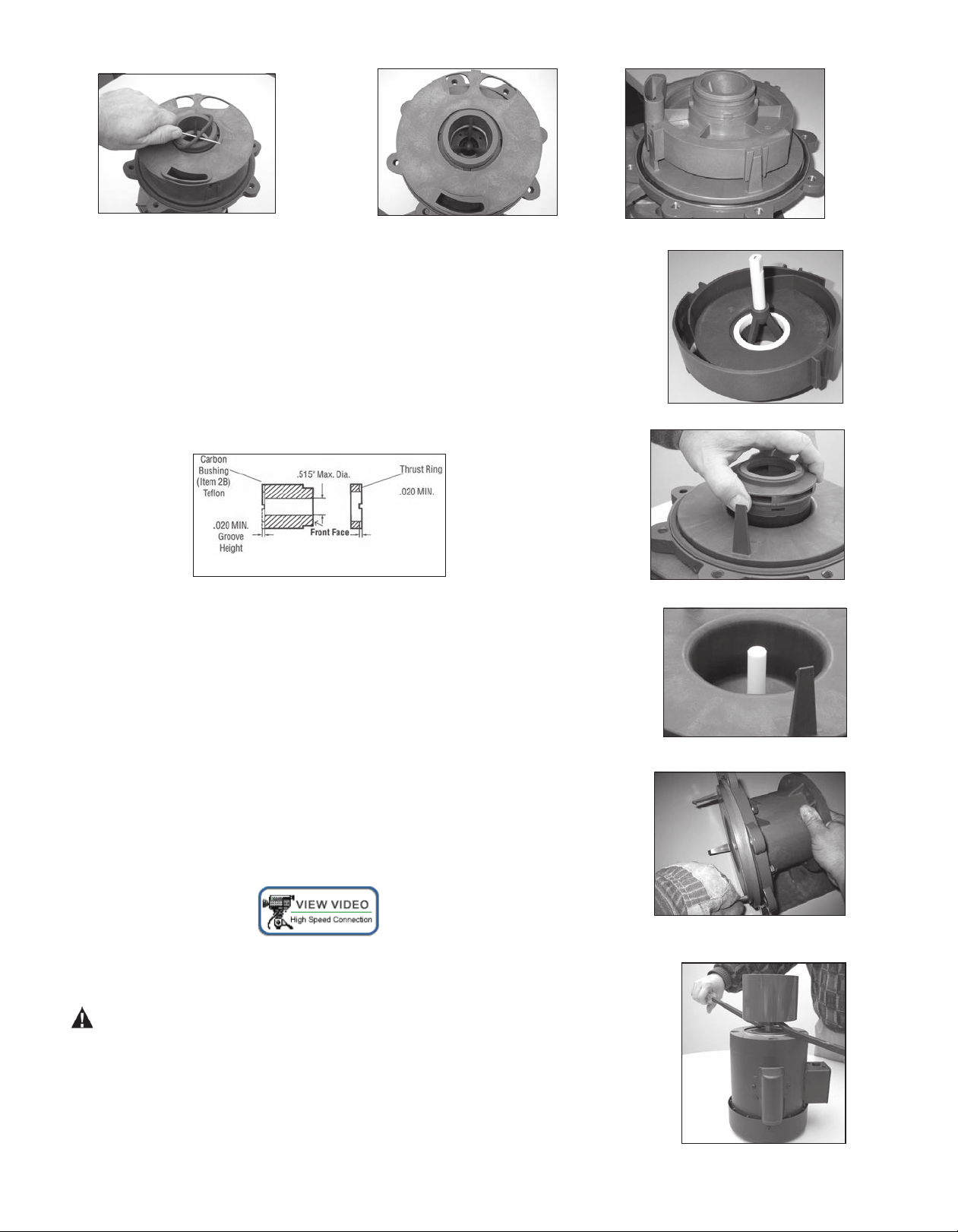
Figure 16
Figure 17
9. Pull the inner volute straight off. Be careful, the impeller shaft may come out
with the inner volute. See gure 19. Inspect inner volute for signs of wear or
damage. Look for signs of rubbing or cracking on the ring or damage to the front
shaft support.
10. Remove impeller/inner drive assembly (items 7A, 7, 8, 8A). Inspect impeller and
drive for signs of wear or damage. Look for signs of rubbing, damage and wear
to the impeller and inner drive. See gure 20. Check the impeller thrust ring and
bushing for wear. See gure 21.
Figure 18
Figure 19
Figure 21
11. Remove the impeller shaft (item 9) from the barrier or inner volute and check
for signs of cracking, chipping, scoring or wear. See gure 22.
12. Remove the barrier (item 11) from the motor adapter (item 12) (make sure
the impeller shaft has been removed). Pull on one of the three prongs to remove
the barrier. Note: Prongs are sharp. Use a glove or rag for better grip. Inspect the
inside and outside of the barrier for signs of rubbing. See gure 23.
13. Remove the o-ring (item 10) from the barrier and inspect for chemical attack,
swelling, brittleness, cuts, etc.
14. Visually inspect the outer drive (item 13) for rubbing, damage, corrosion or loose
magnets.
Outer Drive Replacement
1. Remove the setscrews (item 13A) from the side of the drive (NEMA motors) or
the bolt, lock washer and at washer (items 19, 20, 21) from the center of the
drive (metric motors).
WARNING: Be careful, tools will want to be attracted to the magnets.
Figure 20
Figure 22
Figure 23
2. Remove the drive magnet from the motor shaft by gently
prying up from the bottom of the drive. See gure 24.
3. To reinstall the drive or a new drive follow the instructions from
Section I - Assembly, Pumps without Motors, Steps 4-6.
13
Figure 24
Page 13
Thrust Ring Replacement
1. Thrust ring (item 7A) is held in-place with a snap t with a ridge. Using a razor knife or side cutters, cut a notch
out of the thrust ring. Pull ring up and out of the holder. See gures 25 and 26.
2 To reinstall, align the two ats on the thrust ring with the ats in the bore of the impeller. Using a piece of wood
press into place using an arbor press until the thrust ring is completely seated in the impeller.
Figure 25
Figure 26
Bushing Replacement
1. To remove the bushing, place the impeller/inner drive assembly in an arbor press. Insert a 3/4” diameter plastic or
wood shaft through the eye of the impeller and press the bushing out.
2. To replace the bushing (item 8A), place the top of the impeller on an arbor press with the thrust ring face down.
Insert the front of the bushing (gure 27) into the center of the impeller/inner drive magnet assembly, aligning the
at on the bushing with the at in the bore of the inner drive magnet. Using a soft arbor, press into place until the
bushing reaches the shoulder molded into the inner drive (gures 28, 29).
Figure 27
Figure 28
Figure 29
Impeller Replacement
CAUTION: Do no damage the outer surface of the inner drive magnet during impeller replacement.
Using the two slots provided, insert a at blade screwdriver into them and pry the impeller (items 7A, 7) up from the
body of the inner drive magnet (items 8, 8A). Once a gap has been established, work around the perimeter to evenly
increase the gap until the impeller can be removed. See gure 30.
To install a new impeller, place the inner drive magnet assembly face up (splines
facing up) on an arbor press. Align the spines in the impeller with the ones in the
bore on the inner drive magnet. Place a piece of wood over the top of the impeller thrust ring. Using an arbor press, push down on the impeller until it is completely seated in the inner drive.
13
Figure 30
Page 14

Section VI - Clamp Ring Replacement and Reassembly
1. Inspect the clamp ring. If clamp ring requires replacement, it is recommended to remove the plastic foot (item 15)
rst. NOTE: 100/112 frame B5 adapters do not use the foot. See gures 32 and 33. Remove the four (4) M6 bolts
(items 28 and 28A).
Figure 32
Figure 33
2. Remove the ve (5) M8 bolts, lock washers and at washers (items 34, 33, and 32) from the clamp ring (item
12B). See gure 34. Remove the clamp ring from the motor adapter. There is a snug t between the clamp ring
and motor adapter due to the vapor protection o-ring (item 12C). Carefully pull the two parts apart. See gure 35.
Figure 34 Figure 35
3. Inspect the motor adapter o-ring (item 12C). Replace if damaged. If it is reusable, lubricate it with a chemically compatible lubricant. See gure 36.
4. Install the new clamp ring. Place the clamp ring on a at surface. See gure
37. Align the bolt holes (ve motor adapter and two foot bolt holes) on the
clamp ring with the bolt holes on the motor adapter. Push the motor adapter
straight down onto the clamp ring to seat the o-ring. See gure 38. Install ve
M8 bolts, lock washers and at washers (items 34, 33 and 32) and tighten in a
Figure 36
star pattern to 130 in-lbs. (14.7 N-m). See gure 39.
Figure 37 Figure 38
14
Figure 39
Page 15

5. For 56C, 145TC and 80 frame B14, re-install the plastic
foot (item 15) to the motor adapter (item 12D). Use the
longer M6 bolts, lock washers and at washers (items 28A,
29 and 30) for the front bolt holes towards the clamp ring.
See gure 40. Use the shorter M6 bolts, lock washers and
at washers (items 28, 29 and 30) for the rear bolt holes
towards the motor face. NOTE: Nuts (item 31) are glued
into the rear of the motor adapter to help with the installa-
Figure 40
Figure 41
tion of the rear bolts. Make sure the nuts are still in place.
See gure 41. Tighten bolts to 5 ft-lbs. (6.8 N-m). For 184 frame, IEC 90, 100/112 frame B14 and 80/90 frame
B5, leave the foot off until the motor adapter is installed on the motor. This will allow easier access to the bottom
bolt hole in the motor adapter.
6. Position the motor adapter assembly on a at surface. If the foot is installed, allow the feet to hang over the edge.
see gure 42. Install the o-ring (item 12A) into the groove on the clamp ring. Lubricate the o-ring with a compat-
ible lubricant. See gure 43.
Figure 42
Figure 43
Figure 43A
7. Install the barrier (item 11) into the clamp ring (item 12B). Line up the prong that has no prong opposite it with
the 2 o’clock housing bolt hole in the clamp ring. See gure 43A. NOTE: Leave the barrier loose in the clamp
until installing the housing (item 1) to make sure the bolt holes line up.
8. Install o-ring (item 10) in groove in barrier. Make sure it is tucked in all the way around. See gure 44.
9. Install impeller shaft (item 9) into barrier by aligning the ats on the shaft with the ones in the barrier. Make sure
it is completely seated. See gure 44
10. Carefully install the impeller/inner drive assembly (items 7A, 7, 8, 8A) by sliding it over the impeller shaft in the bar-
rier. It is normal for the impeller/inner drive to pop up a slight amount due to magnetic forces. See gures 45 and 46.
Figure 44
Figure 45
Figure 46
11. Install the inner volute (item 6) by lining up the prongs of the barrier with the channels in the inner volute. Press
down evenly until the prongs snap onto the surface of the inner volute. See gures 47 and 48.
16
Page 16

Figure 47
Figure 48
12. Install the separator plate (item 4) by lining up the bottom opening of the inner volute with the opening in the
plate. Line up the slots in the separator plate with the notches in the inner volute. See gure 49.
13. Lubricate the inner volute o-ring (item 5) with a chemically compatible lubricant and install in the groove on the
round suction nozzle in the center of the inner volute. See gure 50.
Figure 49
Figure 50
14. Lubricate the inside of the gooseneck. See gure 51. Install the housing (item 1). Line up the tab on the top of the
separator plate with the notch in the housing (located inside the front of the housing near the discharge port). See
Figure 51. Using uniform pressure, press the housing and barrier into place until it is ush with the motor adapter.
See gure 52.
Figure 51
Figure 52
Note: The t is tight due to inner volute o-ring. Make sure o-ring is lubricated.
Install the housing bolts, lock washers and at washers (items 16, 17, 18). Tighten all bolts evenly using a star pat-
tern. Tighten to 20 foot-lbs (27 N-m).
15. Reinstall the pump on the motor/drive magnet following instructions found in “Assembly, Pumps without Mo-
tors,” steps 7-10.
16
Page 17

SP11 / SP15 PART NUMBER EXPLANATION
NOTE: Pump end includes wetted components, drive magnet and motor adapter. The wet end incudes wetted components only.
Part Number Explanation
The base model number contains standard components. Where standard components are not suitable, add the alternative component code
after the base model number to substitute components. Example: SP11-E-U-14 is constructed of the listed base model components except it
has an EPDM o-rnig, union connections, and a 145TC motor adapter.
The model number is on the serial number label located on the motor adapter. The model number contains a base model that features certain
standard components.
Compare the model number on the pump to the adjacent chart to determine if the pump contains any alternate components. Model numbers
containing “P” have primary components molded from polypropylene. Model numbers containing “V” have primary components molded from
PVDF.
Base model numbers are: SP11P, SP11V.
Alternative Components
Component▼ Base▼ Code▼
Alternative▼
Bushing Carbon
O-ring FKM
Connection NPT
Impeller
Magnet
(Upgrade for
specific gravity
corrections)
1 (60 Hz)
4.63”
6-pole
Up
to 2 HP /1.5 kW
(56C/145/80/90
frame)
Motor Adaptor 56C NEMA
or
or
or
2 (60 Hz) 3 (60 Hz) 4 (60 Hz) 5 (60 Hz) 6 (50 Hz) 7 (50 Hz) 8 (50 Hz) 9 (50 Hz) 10 (50 Hz)
or
4.38” 4.13” 3.88" 3.63" 5.25" 5.00" 4.75" 4.50" 4.25"
8-Pole: 3 HP/2.2 kW (56C/145//80/90 frame)
or
10-Pole: 4 to 5 HP/ 3 to 4 kW (184/100/112 frame and "Ge" gas engine)
or
Gas engine mounting (requires 10-pole upgrade)
PTFE
Alumina Ceramic
EPDM
BSP
Union
Steel Enforced Flange
FRP flange
145TC NEMA
184TC NEMA
IEC 80/B14
IEC 90/B14
IEC 100/B14
IEC 112/B14
IEC 80/B5
IEC 90/B5
IEC 100/B5
IEC 112/B5
T
R
E
B
U
Fs
Ff
8p
10p
14
18
84
94
04
24
85
95
05
25
Ge
Specials Not Standard
Motor Not Standard
SiC bushing/thrust ring/shaft
Hastelloy shaft
Titanium Hardware
Non-sparking ring
O-ring vapor protection kit - FKM
O-ring vapor protection kit - EPDM
Select Motor Reference Number from Motor Price Sheets
17
Si
Hs
Ti
Ns
Vv
Ve
Page 18

26
14
27
24
25
22
20
15
29
30
28
12D
10
8
7
7A
11
8A
9
17
18
16
1
5
2
4
3
6
23
19
21
13B
13A
3A
SP11/15 Parts Diagram
28A
12A
12B
12C
32
33
34
31
SP11/15 PARTS DRAWING
18
Page 19

Item Qty Description
Housing
NPT threads 105862 105862-1 105862 105862-1
1 1
2 1
3 2
3A 2
4 1
5 1
6 1
7 1
7A 1
BSP threads 105862-2 105862-3 105862-2 105862-3
Steel flanges 105866 105866-2 105866 105866-2
Fiberglass flanges 105866-1 105866-3 105866-1 105866-3
Unions 105867 105867-1 105867 105867-1
Discharge O-Ring (BSP Threaded Housings Only)
EPDM 105918
FKM 105919
Fill/Drain Plug
Fill Plug O-Ring
EPDM 106154
FKM 106155
Separator Plate
Inner Volute O-Ring
EPDM J103478
FKM J103477
Inner Volute (Select For Appopriate Impeller Diameter)
#1 impeller (4.63”/SP11, 5.13”/SP15) w/ ceramic ring 105864-2 105864-3 105865-2 105865-3
#2 impeller (4.38”/SP11, 5.00”/SP15) w/ ceramic ring 105864-4 105864-5 105865-4 105865-5
#3 impeller (4.13”/SP11, 4.75”/SP15) w/ ceramic ring 105864-6 105864-7 105865-6 105865-7
#4 impeller (3.88”/SP11, 4.50”/SP15) w/ ceramic ring 105864-8 105864-9 105865-8 105865-9
#5 impeller (3.63”/SP11, 4.25”/SP15) w/ ceramic ring 105864 105864-1 105865 105865-1
#6 impeller (5.25”/SP11, 5.50”/SP15) w/ ceramic ring 105864-10 105864-11 105865-10 105865-11
#7 impeller (5.00”/SP11, 5.25”/SP15) w/ ceramic ring 105864-12 105864-13 105865-12 105865-13
#8 impeller (4.75”/SP11, 5.00”/SP15) w/ ceramic ring 105864-14 105864-15 105865-4 105865-5
#9 impeller (4.00”/SP11) w/ ceramic ring 105864-16 105864-17 N/A N/A
#10 impeller (4.25”/SP11) w/ ceramic ring 105864-18 105864-19 N/A N/A
#1 impeller (4.63”/SP11, 5.13”/SP15) w/ SiC ring 105909-2 105909-3 105910-2 105910-3
#2 impeller (4.38”/SP11, 5.00”/SP15) w/ SiC ring 105909-4 105909-5 105910-4 105910-5
#3 impeller (4.13”/SP11, 4.75”/SP15) w/ SiC ring 105909-6 105909-7 105910-6 105910-7
#4 impeller (3.88”/SP11, 4.50”/SP15) w/ SiC ring 105909-8 105909-9 105910-8 105910-9
#5 impeller (3.63”/SP11, 4.25”/SP15) w/ SiC ring 105909 105909-1 105910 105910-1
#6 impeller (5.25”/SP11, 5.50”/SP15) w/ SiC ring 105909-10 105909-11 105910-10 105910-11
#7 impeller (5.00”/SP11, 5.25”/SP15) w/ SiC ring 105909-12 1015909-13 105910-12 105910-13
#8 impeller (4.75”/SP11, 5.00”/SP15) w/ SiC ring 105909-14 105909-15 105910-4 105910-5
#9 impeller (4.00”/SP11) w/ SiC ring 105909-16 105909-17 N/A N/A
#10 impeller (4.25”/SP11) w/ SiC ring 105909-18 105909-18 N/A N/A
Impeller Assembly (Select Appropriate Impeller Diameter)
See SP11/15 Impeller Assemblies Table
Impeller Thrust Ring Only
Filled PTFE 105694-1
Silicon carbide 105694-3
SP11/SP15 Spare Parts List
SP11 SP15
Pump Material Pump Material
PP PVDF PP PVDF
106143 106143-1 106143 106143-1
105863 105863-1 105863 105863-1
19
Page 20

SP11/15 Spare Parts List - cont.
Item Qty Description
Impeller Drive Assembly
6-Pole with carbon bushing 105913 105913-3 105913 105913-3
8-Pole with carbon bushing 105913-1 105913-4 105913-1 105913-4
10-Pole with carbon bushing 105913-2 105913-5 105913-2 105913-5
6-Pole with PTFE bushing 105913-6 105913-9 105913-6 105913-9
8-Pole with PTFE bushing 105913-7 105913-10 105913-7 105913-10
8 1
10-Pole with PTFE bushing 105913-8 105913-11 105913-8 105913-11
6-Pole with alumina ceramic bushing 105913-12 105913-15 105913-12 105913-15
8-Pole with alumina ceramic bushing 105913-13 105913-16 105913-13 105913-16
10-Pole with alumina ceramic bushing 105913-14 105913-17 105913-14 105913-17
6-Pole with silicon carbide bushing 105913-18 105913-21 105913-18 105913-21
8-Pole with silicon carbide bushing 105913-19 105913-22 105913-19 105913-22
10-Pole with silicon carbide bushing 105913-20 105913-23 105913-20 105913-23
Impeller Bushing Only
Carbon J100977
8A 1
Filled PTFE 106386
Alumina ceramic 106386-2
Silicon carbide 106386-1
Impeller Shaft
9 1
Alumina ceramic 105811-1
Silicon carbide 105811-2
Hastelloy C 105811-3
O-Ring
10 1
EPDM 105717
FKM 105716
11 1
Barrier
Motor Adapter
12 1
Standard motor adapter - all frame sizes 107405 107406 107405 107406
Standard motor adapter with non-sparking ring - all frame sizes 107407 107408 107407 107408
Note: 182/184TC & all IEC frames MAY need to order motor adapter flange (item 14) and hardware (items 22-24 & 25-27)
Barrier/Clamp Ring O-ring
12A 1
Buna 107281
FKM 107279
EPDM 107280
Clamp Ring
Painted cast iron (Standard) 107228 107228-1 107228 107228-1
12B 1
Painted cast iron with non-sparking ring 107322 107322-1 107322 107322-1
Stainless steel 108600 108600 108600 108600
Stainless steel with non-sparking ring 108600-1 108600-1 108600-1 108600-1
Clamp Ring/Motor Adapter Column O-ring
12C 1
Buna 107282
FKM 107283
EPDM 107284
12D 1
Motor Adapter Column
Standard 106890 106890-1 106890 106890-1
SP11 SP15
Pump Material Pump Material
PP PVDF PP PVDF
105689-3 105689-4 105689-3 105689-4
20
Page 21

SP11/15 Spare Parts List - cont.
Item Qty Description
Motor Adapter column to motor o-ring (NEMA 56C/145TC motors only)
12E 1
Buna 106549
FKM 106374
EPDM 106373
Drive Magnet Assy
6-Pole 56C frame - includes set screws and snap ring 105878
8-Pole 56C frame - includes set screws and snap ring 105878-1
6-Pole 143/145TC frame - includes set screws and snap ring 105878-3
8-Pole 143/145TC frame - includes set screws and snap ring 105878-4
13 1
10-Pole 182/184TC frame - includes set screws and snap ring 105730-9
6-Pole 80 frame - includes snap ring 105882
8-Pole 80 frame - includes snap ring 105882-1
6-Pole 90 frame - includes snap ring 105882-3
8-Pole 90 frame - includes snap ring 105882-4
10-Pole 100/112 frame- includes snap ring 105730-18
13A 2
Set Screws- NEMA Motors Only
Snap Ring
56C frame 105708
143/145TC frame 105709
13B 1
182/184TC frame 105710
80 frame 105711
90 frame 105712
100/112 frame 105710
Motor Adapter Flange
182/184TC frame 105751-1 105751-2 105751-1 105751-2
80 frame with B14 flange 105724-1 105724-2 105724-1 105724-2
14 1
90 frame with B14 flange 105725-1 105725-2 105725-1 105725-2
100/112 frame with B14 flange 105726-1 105726-2 105726-1 105726-2
80/90 frame with B5 flange 106274 106274-1 106274 106274-1
100/112 frame with B5 flange 107315 107315-1 107315 107315-1
Foot (100/112 frame pumps with B5 flange do not include a pump foot)
15 1
All frames sizes except 100/112 105691-1 105691-4 105691-1 105691-4
100 frame with B14 flange 105691-3 105691-6 105691-3 105691-6
112 frame with B14 flange 105691-2 105691-5 105691-2 105691-5
SP11 SP15
Pump Material Pump Material
PP PVDF PP PVDF
J101084
21
Page 22

Hardware - All SP11/15 Models
Item Qty Description Stainless Steel Titanium
16 8
17 8
18 8
19 1
20 1
21 1
22 4
23 4
24 4
25* 4
26* 4
27* 4
28 2
28A 2
29 4
30 4
31 2
32 5
Housing bolt
106210 106211
Housing Lock Washer
105757 105758
Housing Flat Washer
105722 105773
Drive Bolt- IEC Motors Only
80 frame IEC 105765 105766
90 frame IEC 105770 105771
100/112 frame IEC 105774 105775
Drive Lockwasher
80 frame IEC J100672 J104203
90 frame IEC J102282 J103847
100/112 frame IEC J100115 J104206
Drive Flatwasher
80 frame IEC 105767 105768
90 frame IEC 105722 105773
100/112 frame IEC J101360 106200
Motor Adapter Bolts
All frames except 100/112 B5 J103118 105752
100/112 B5 frames only J100114 106311
Motor Adapter Lockwasher
J100115 J104206
Motor Adapter Flatwasher
J100128 J104207
Motor Adapter Flange Bolts
182/184 Frame J103782 105761
80 Frame B14 IEC J103780 105764
90 Frame B14 IEC 105770 105771
100/112 Frame B14 IEC 105770 105771
Lockwasher- Motor Adapter Flange
182/184 Frame J101023 105762
80 Frame B14 IEC J100672 J104203
90 Frame B14 IEC J102282 J103847
100/112 Frame B14 IEC J102282 J103847
Flatwasher- Motor Adapter Flange
182/184 Frame J103851 105763
80 Frame B14 IEC J100113 J104204
90 Frame B14 IEC J101293 J103845
100/112 Frame B14 IEC J101293 J103845
Rear Foot Bolt
J103968 107288
Front Foot Bolt
107289 107290
Foot Lockwasher
J100672 J104203
Foot Flatwasher
J100113 J104204
Nut- Rear Foot Bolt
107286 107287
Clamp Ring Flatwasher
J101293 105768
22
Page 23

Hardware - cont.
Item Qty Description Stainless Steel Titanium
33 5
34 5
*For IEC B5 frame pumps: Hardware is to be supplied by customer due to variations in B5 frame motors.
Clamp Ring Lockwasher
J102282 J103847
Clamp Ring Bolt
J103662 107285
SP11
SP15
Thrust
Ring
PTFE
SiC
Thrust
Ring
PTFE
SiC
Impeller
Material
Polypro
PVDF
Polypro
PVDF
Impeller
Material
Polypro
PVDF
Polypro
PVDF
SP11/15 Impeller Assemblies
#1 #2 #3 #4 #5 #6 #7 #8 #9 #10
4.63" 4.38" 4.13" 3.88" 3.63" 5.25" 5.00" 4.75" 4.50" 4.25"
105911 105911-4 105911-6 105911-8 105911-10 105911-2 105911-14 105911-16 105911-18 105911-20
105911-1 105911-5 105911-7 105911-9 105911-11 105911-3 105911-15 105911-17 105911-19 105911-21
105915 105915-4 105915-6 105915-8 105915-10 105915-2 105915-14 105915-16 105915-18 105915-20
105911-1 105915-5 105915-7 105915-9 105915-11 105915-3 105915-15 105915-17 105915-19 105915-21
#1 #2 #3 #4 #5 #6 #7 #8 - -
5.13” 5.00" 4.75" 4.50" 4.25" 5.50" 5.25" 5.00" - -
105911-12 105916 105916-4 105916-6 105916-8 105916-10 105916-12 105916-14 - -
105911-13 105916-2 105916-5 106916-7 105916-9 105916-1 105916-13 105916-15 - -
105915-12 105917 105917-4 105917-6 105917-8 105917-10 105917-12 105917-14 - -
105915-13 105917-2 105917-5 106917-7 105917-9 105917-1 105917-13 105917-15 - -
23
Page 24

Section VII - Troubleshooting
General Notes:
• Cold water can contain dissolved air. Under high lift applications, the air can come out of solution blocking suction passages.
This can lead to lack of priming, slow priming or low ow rates.
Do not pump liquids containing ferrous metal nes.
• If magnets de-couple, stop pump immediately. Operating the pump with the magnets de-coupled will eventually weaken the
magnets.
• Do not use mismatched drive magnet assemblies (different number of magnets on inner and outer drive magnet assemblies).
• Contact our Technical Service Department at 1-800-888-3743 or by e-mail at techservice@nishthompson.com if you have
any questions regarding product operation or repair.
No or Insufficient Discharge
• Air leaks in suction piping
• Housing not lled with priming uid
• Suction pipe smaller than 1 1/2”
• Suction pipe contains high spots causing trapped air pockets
• Suction pipe excessively long (ow drops as suction pipe gets longer)
• System head higher than anticipated
• Closed valve
• Viscosity or specic gravity too high
• Motor too large for magnet coupling rating (magnets uncoupled)
• Suction lift too high or insufcient NPSH
• Clogged suction line, suction strainer (if used) or impeller vanes
Insufficient Pressure
• Air or gas entrained liquid
• Impeller diameter too small
• System head lower than anticipated
• Motors speed insufcient (too low) or motor rotation incorrect (correct rotation when viewed from the fan end is clockwise)
Won’t Prime
• Did not ll housing with uid before initially starting pump
• Closed discharge valve (valve should be open or open air vent line)
• Leak in suction piping
• Suction pipe not submerged enough (causing a vortex or exposing the end of the suction pipe)
• Lift exceeds pump ability (see SP11/15 Capabilities section)
• Suction pipe diameter too large
• Specic gravity or local atmospheric pressure (altitude/elevation) not accounted for in lift calculations
• Mismatch of inner volute and impeller diameter
• Inner volute o-ring chemically attacked, cut, brittle, etc.
• Motor rotation incorrect (correct rotation when viewed from the fan end is clockwise)
• Check valve installed too close to the pump
24
Page 25

Primes Slowly
• Mismatch of inner volute and impeller diameter
• Suction pipe diameter too large (larger than 1 1/2”)
• Closed discharge valve (valve should be open)
• Inner volute o-ring chemically attacked, cut, brittle, etc.
Excessive Power Consumption
• Head lower than rating
• Excessive ow
• Specic gravity or viscosity too high.
Vibration/Noise
• Loose magnet
• Drive magnet rubbing
• Pump cavitating from improper suction or feed
• Motor or piping not properly secured
• Foreign object in impeller
Section VIII - Warranty
Finish Thompson, Inc (manufacturer) warrants this pump product to be free of defects in materials and workman-
ship for a period of ve years from date of purchase by original purchaser. If a warranted defect, which is determined
by manufacturer’s inspection, occurs within this period, it will be repaired or replaced at the manufacturer’s option,
provided (1) the product is submitted with proof of purchase date and (2) transportation charges are prepaid to the
manufacturer. Liability under this warranty is expressly limited to repairing or replacing the product or parts thereof
and is in lieu of any other warranties, either expressed or implied. This warranty does not apply to normal wear of the
product or components. This warranty does not apply to products or parts broken due to, in whole or in part, accident,
overload, abuse, chemical attack, tampering, or alteration. The warranty does not apply to any other equipment used
or purchased in combination with this product. The manufacturer accepts no responsibility for product damage or per-
sonal injuries sustained when the product is modied in any way. If this warranty does not apply, the purchaser shall
bear all cost for labor, material and transportation.
Manufacturer shall not be liable for incidental or consequential damages including, but not limited to process down
time, transportation costs, costs associated with replacement or substitution products, labor costs, product installation
or removal costs, or loss of prot. In any and all events, manufacturer’s liability shall not exceed the purchase price
of the product and/or accessories.
Ordering Spare Parts
Spare parts can be ordered from your local distributor. Always refer to the pump model to avoid error.
25
Page 26

Part Number 107404, Rev11, 2/14/2014
Order fax: 814-459-3460
Tech Service: 800-888-3743
Literature ID No. FT09-1093
 Loading...