

Page 1
PF SERIES PUMPS
PFS
OPERATION & PARTS MANUAL
For Serial Number 162858 & lower
Page 2

EU Declaration of Conformity
Finish Thompson Inc. hereby declares that the following machine(s) fully comply with the
applicable health and safety requirements as specified be the EC Directives listed.
The product may not be taken into service until it has been established that the drive motor
for the Drum and Container Pump complies with the provisions of all relevant EC Directives.
The complete product complies with the provisions of the EC Directive on machinery safety
provided motors manufactured by Finish Thompson Inc. are used.
This declaration is valid provided that the devices are fully assembled and no modifications
are made to these devices.
BTS – 40 EPPI/EPPS 15/27/40 EFP/EFV/EFS-16/27/40/48
HVDP LR-27/40/48 HVDP HR-27/40/28 PFM-27/40/48/60
PFP-15/27/40/48/60/72 PFS-27/40/48/60/72 PFV-27/40/48/60/72
TBP-27/40/48 TBS-40 TTC/TTS -27/40/48
STTS-40 TMS-40
Type of Device:
Drum and Container Pump Tubes
Models:
EC Directives:
Machinery Safety (2006/42/EC)
Applied Harmonized Standards:
EN ISO 12100 Part 1
EN ISO 12100 Part 2
EN 809
Manufacturer:
Finish Thompson Inc.
921 Greengarden Road
Erie, Pennsylvania 16501-1591 U.S.A
Signed,
_
President
January 7, 2013
Person(s) Authorized to Compile Technical File: Michael Smith Engineers Limited
Oaks Road, Woking, Surrey
GU21 6PH, UK
Telephone: 01483 771871
Page 3
Introduction
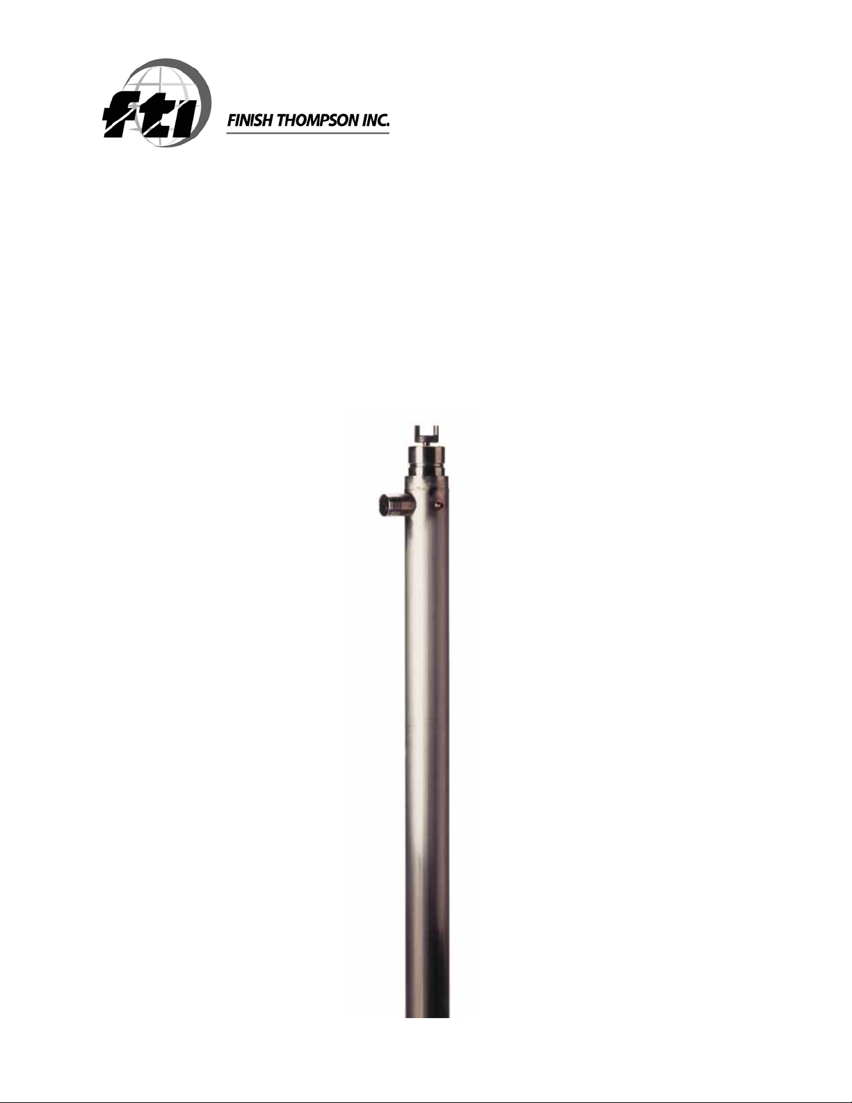
This manual pertains to the PF Series, specifically the PFS stainless steel drum pump. Finish Thompson Inc. thanks
you for choosing our products. We believe the use of our products will be fully satisfactory. When properly installed
and operated, your Finish Thompson motor and pump will provide long, trouble-free service; therefore, please read
this manual carefully before carrying out any operations on the pump/motor unit. Any use other than that described
herein is considered incorrect; and, consequently, Finish Thompson Inc. shall not be held responsible for any damages to people or property. In case of doubt or enquiries, please reply to our Technical Service department directly at
the following address:
Finish Thompson, Inc.
921 Greengarden Rd.
Erie, PA 16501 U.S.A.
Tel. 1-814-455-4478; Fax 1-814-455-8518
www.finishthompson.com; fti@finishthompson.com
Index
Introduction .............................................................................................................................1
Pump Specifications ................................................................................................................ 1
Warranty, General Terms & Conditions ...................................................................................... 2
Safety ......................................................................................................................................3
Installation ...............................................................................................................................4
Maintenance
Disassembly ....................................................................................................................... 4
Inspection ........................................................................................................................... 4
Reassembly ........................................................................................................................ 5
Exploded View .........................................................................................................................6
Pump Tube Spare Parts List ..................................................................................................... 7-8
Technical Service Hotlne: 1-800-888-3743 or email techservice@finishthompson.com
PUMP SPECIFICATIONS
Outer Tube Diameter 2” (51 mm)
Discharge Type 1” hose barb
Max. Specific Gravity 1.83
Max. Viscosity 2000 cP
Min./ Max. Fluid
Temperature
Wetted Materials 316 Stainless Steel, FKM, PTFE, ETFE
-20°F (5° F with Perlast o-rings) Min. to 220° F Max.
[-4° C (21° C) Min. to 105° C Max.]
MODEL PFS
1
Page 4

Warranty, General Terms & Conditions
1. The following terms and conditions apply to the sale of machinery, components and related services and products, of Finish
Thompson Inc. (hereinafter “the products”)
2. Finish Thompson Inc. (the manufacturer) warrants only that:
a) its products are free of defects in material, design and workmanship at the time of original purchase;
b) its products will function in accordance with Finish Thompson Inc. operation manuals; Finish Thompson Inc. does not
guarantee that the product will meet the precise needs of the Customer, except for those purposes set out in any invitation
to render documents or other documents specifically made available to Finish Thompson Inc. before entering into this
agreement;
c) high quality materials are used in the construction of the pumps and that machining and assembly are carried out to the
highest standards. Except as expressly stated above, Finish Thompson Inc. makes no warranties, express or implied,
concerning the products, including all warranties of fitness for a particular purpose.
This warranty shall not be applicable in circumstances other than defects in material, design, and workmanship. In particular
warranty shall not cover the following:
d) Periodic checks, maintenance, repair and replacement of parts due to normal wear and tear;
e) Damage to the product resulting from:
i. Tampering with, abuse or misuse, including but not limited to failure to use the product for its normal purposes as
stated at the time of purchase or in accordance with Finish Thompson, Inc. instructions for use and maintenance of the
product, or the installation or improper ventilation or use of the product in a manner inconsistent with the technical or
safety standard in force;
ii. Repairs performed by non-authorized service workshop, or opening of the unit by non-authorized personnel, or use of
non genuine Finish Thompson Inc. parts;
iii. Accidents, force majeure or any cause beyond the control of Finish Thompson Inc., including but not limited to light ning, water, fire, earthquake, and public disturbances, etc.
3. The warranty shall cover the replacement or repair of any part, which is documented to be faulty due to construction or as sembling, with new or repaired parts free of charge delivered by Finish Thompson, Inc. Parts subjected to normal wear and
tear shall not be covered by the warranty. Finish Thompson, Inc. shall decide as to whether the defective or faulty part shall be
replaced or repaired. Transportation charges are prepaid to Finish Thompson.
4. The warranty of the products shall be valid for a period of 12 months from the date of delivery, under the condition that notice
of the alleged defect to the products or parts thereof be given to Finish Thompson, Inc. within the term of 8 days from the
discovery.
5. Repair or replacement under the terms of this warranty shall not give a right to an extension to, or a new commencement of,
the period of warranty. Repair or replacement under the terms of this warranty may be fulfilled with functionally equivalent re conditioned units. Finish Thompson Inc. qualified personnel shall be solely entitled to carry out repair or replacement of faulty
parts after careful examination of the motor. Faulty parts or components when replaced by Finish Thompson Inc. will become
the property of Finish Thompson Inc. If this warranty does not apply, the purchaser shall bear all cost for labor, material and
transportation.
6. Finish Thompson Inc. will not be liable on any claim, whether in contact, tort, or otherwise, for any indirect, special, incidental,
or consequential damages, caused to the customer or to third parties, including loss of profits, process down time, transpor tation costs, costs associated with replacement or substitution products, labor costs, installation or removal costs. In any and
all events, manufacturer’s liability shall not exceed the purchase price of the product and/or accessories.
7. Return Policy. Should you have any problems with this product, please contact the distributor in your area. The distributor
will determine if a return to the factory is necessary and will contact the factory for a Return Authorization Number. Otherwise,
contact our Technical Service Hotline (1-800-888-3743) or e-mail techservice@finishthompson.com if you have any questions
regarding product operation or repair.
2
Page 5

Safety
1. Introduction
This manual contains all the information needed for the correct installation, use and maintenance of your new Finish Thompson
pump. It should be read and understood by all the personnel involved in installation, operating and servicing of the pump before
it is started.
2. Operator Qualification and Training
The personnel in charge of the installation, the operation, and the maintenance of the pump must be qualified and able to per form the operations described in this manual. Finish Thompson, Inc. shall not be held responsible for the training level of
personnel and for the fact that they are not fully aware of the contents of this manual.
3. Safety Instructions
FOR YOUR OWN SAFETY
BEFORE using or servicing your pump, please make sure to wear the proper clothing, eye protection and follow standard safety
procedures when handling corrosive or personally harmful materials.
GENERAL DANGER
ALWAYS use a stainless steel pump tube with an explosion proof electric motor or air motor and static protection kit with
grounded discharge hose when pumping or mixing flammable or combustible material.
NEVER use in pressurized containers.
ALWAYS store unit upright, i.e. motor above pump, and away from corrosive liquids and vapors.
DANGER: POWER SUPPLY
Refer to instructions for the appropriate motor in the Operation & Installation Manual - Drum Pump Motors.
4. Noise Level
Refer to specifications in the Operation & Installation Manual - Drum Pump Motors.
5. Modifications and Spare Parts
Any changes concerning the service of the pump as originally purchased can be executed only after written approval from
Finish Thompson Inc. It is recommended to use only genuine Finish Thompson Inc. spare parts and approved accessories. The
use of non-original spare parts or non-approved accessories will void warranty and removes any responsibility on the manufac turer’s behalf for any damage caused to people or things.
3
Page 6

Installation & Maintenance Instructions
Installation
1. Remove the drum pump and motor from its packaging and inspect for shipping damage.
2. Turn the pump coupling to verify there is no binding. Verify the housing cover (item 16) is on tight (it has
a left hand thread.
3. Adjust the coupling so that the empty slots in the insert are at 3 and 9 o’clock with the pump discharge at 12
o’clock.
4. Install the motor according to instructions in the appropriate motor manual.
5. Attach 1” i.d. discharge hose and secure with hose clamp.
6. Install into the container.
Maintenance
Disassembly
1. Remove the housing cover (item 16) by turning it clockwise (left hand thread) while gripping the impeller
housing (item 13).
2. Turn the impeller until a hole in the shaft can be seen through the square slot in the impeller housing (item
13), and insert 3/32 pin into the hole. Holding the pin, turn the impeller (item 15) counterclockwise (right-
hand thread) and remove it.
3. Remove the impeller housing (item 13) by gripping the intake tube and turning the housing clockwise
(left hand thread).
4. Place a wooden board or rubber mat on the floor (to protect the threads on the bottom of the shaft) and
gently tap the shaft (item 14) on it until the inner tube (item 9), shaft sleeve (item 10), and bottom bearing
(item 3) drops out. Continue to tap the shaft until both bearings (item 3) are exposed at the top of the pump.
5. Pull the bearings and shaft out through the top of the pump.
Inspection
1. Check the housing cover (item 16), the impeller (item 15), and the impeller housing (item 13) for wear, rubbing, or damage from foreign objects. Replace if damaged.
Note: The double impeller design of this pump is dependant on the impeller working correctly. Any damage
to the impeller can cause pump failure.
2. Inspect the pump shaft (item 14) for wear in the bearing (item 11) and the lip seal (item 4) areas. Replace
the shaft if needed.
3. Inspect the bottom bearing (item 11) for internal wear. Inspect all o-rings (items 8 &12) for nicks or chemical attack. Replace as needed.
4. Inspect the bearing assembly (item 3) for rust or corrosion.
5. If the bearing assembly needs to be replaced, unthread it from the shaft. Insert 3/32” pin into the hole at
the bottom and hold the bearing assembly by the half coupling. Turn the shaft counterclockwise (right
hand thread) to loosen and remove. If corroded, then a penetrating fluid may be used on the threads to help
loosen.
Note: Never reuse the lip seal.
4
Page 7

Reassembly
1. Install new lip seal (item 4) into the pump head with the grooved side facing the bottom of the pump.
2. If bearing assembly is replaced -- thread the shaft (item 14) into the bearing assembly (item 3) with the 3/32
hole in the shaft on the other end. Carefully insert the shaft straight through the lip seal (to avoid seal damage) from the top and seat the bearing assembly (item 3) into the pump head.
3. If o-rings are replaced -- install 2 inner tube o-rings (item 8) in the grooves. Install the impeller housing o-
ring (item 12) inside the top of the housing. Apply a small amount of Vaseline to the o-rings to aid in assembly.
4. With the pump on a bench, slide shaft liner (item 10) into the inner tube (item 9) assembly onto the shaft
until it stops. Slide the shaft liner/inner tube/shaft assembly into the outer tube (item 7) using the shaft (item
14) as a guide.
5. Slide the impeller housing over the shaft, center the bottom of the lower inner tube into the counter bore in
the top of the impeller housing, and push / thread into the intake tube bottom (left hand thread).
6. Gripping the coupling at the top of the pump, thread the impeller on (right hand thread). Install the housing
cover (left hand thread). turn the coupling to verify there is no binding inside the pump.
5
Page 8

PFS SPARE PARTS EXPLODED VIEW
Not Pictured: Item 25 (Middle Inner Tube - 60” & 72” pump lengths only) &
Item 26 (Lower Middle Inner Tube - 72” pump length only)
6
Page 9

PUMP SPARE PARTS LIST
(for serial numbers 162858 and lower)
ITEM QTY DESCRIPTION PART NUMBER
1 1
2 1
3* 1
4* 1
6 1
7 1
8 1
10* 2
11 1
12* 1
13* 1
14* 1
15 1
16* 1
17 1
†
18
19 1
20* 1
1
COUPLING INSERT
J100014
COUPLING HALF
J100012
BEARING ASSEMBLY
A101110
VAPOR SEAL
M100008
LOCK WASHER
#8 BRASS J100823
SCREW
#8-32 X 1/4 BRASS PAN HEAD J100822
INTAKE TUBE ASSEMBLY
27” MODELS A101725-1
40” MODELS A101725-3
48” MODELS A101725-4
60” MODELS A101725-5
72” MODELS A101725-6
INNER TUBE O-RING
FKM J100249
EPDM 106519
PERLAST 105621
STAINLESS STEEL UPPER INNER TUBE
27” MODELS M100786-1
40” MODELS M100786-3
48” MODELS M100786-4
60” MODELS M100786-3
72” MODELS M100786-3
CENTER BEARING O-RING
FKM J100018
EPDM 106798
PERLAST 105620
CENTER BEARING
PTFE M100010
BEARING GUIDE
PTFE M101603-3
LOWER INNER TUBE
27” MODELS M100789-1
40” MODELS M100789-3
48” MODELS M100789-4
60” MODELS M100789-3
72” MODELS M100789-3
BOTTOM BEARING
PTFE M100007
IMPELLER HOUSING O-RING
FKM J100019
EPDM 106799
PERLAST 105622
IMPELLER HOUSING (sold as a kit with Item 21)
Stainless steel 108131
SHAFT
27” MODELS M100004-5
40” MODELS M100004-7
48” MODELS M100004-8
60” MODELS M100004-12
72” MODELS M100004-13
PFS IMPELLER ASSEMBLY
A100002-3
7
Page 10

†
21
1
PFS HOUSING COVER (sold as a kit with Item 18)
See Item 18
UPPER MIDDLE INNER TUBE
27” MODELS N/A
25
40” MODELS N/A
48” MODELS N/A
60” MODELS M100789-3
72” MODELS M100789-3
26 1
LOWER MIDDLE INNER TUBE
72” MODELS M100789-1
*Recommended Spare Parts
†
If replacing either item number 18 or 21, you must order both to assure proper fit.
Note: Bearing assembly and vapor seal can be purchased as a kit using part number 106567.
Rev. 1, 3-5-13
Service 1-800-888-3743
 Loading...