

Page 1
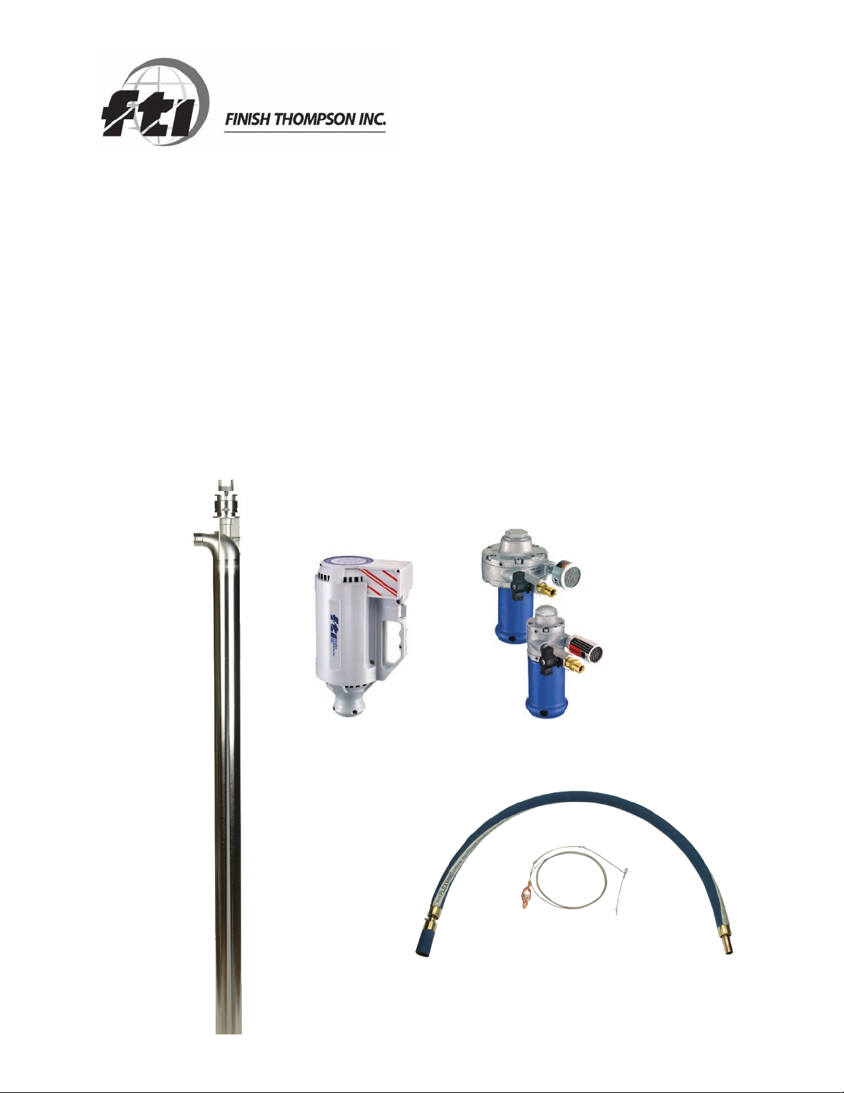
PF SERIES PUMPS
PFS ATEX VERSION
(INCLUDES M6A, M6XA, M10X MOTORS & SPK)
OPERATION & PARTS MANUAL
Page 2

Introduction
This manual pertains to the PF Series, specifically the ATEX version of the PFS stainless steel drum pump. Finish
Thompson Inc. thanks you for choosing our products. We believe the use of our products will be fully satisfactory.
When properly installed and operated, your Finish Thompson motor and pump will provide long, trouble-free service; therefore, please read this manual carefully before carrying out any operations on the pump/motor unit. Any
use other than that described herein is considered incorrect; and, consequently, Finish Thompson Inc. shall not be
held responsible for any damages to people or property. In case of doubt or enquiries, please reply to our Technical
Service department directly at the following address:
Finish Thompson, Inc.
921 Greengarden Rd.
Erie, PA 16501 U.S.A.
Tel. 1-814-455-4478; Fax 1-814-455-8518
www.finishthompson.com; fti@finishthompson.com
Index
Introduction ............................................................................................................................. 1
Warranty, General Terms & Conditions ...................................................................................... 2
Safety ...................................................................................................................................... 3
Pump Specifications ................................................................................................................ 4
ATEX Specifications .................................................................................................................5
PFS Installation ........................................................................................................................ 6
Static Protection Kit Assembly .................................................................................................. 6-7
Maintenance
Disassembly ....................................................................................................................... 7
Inspection ........................................................................................................................... 8
Reassembly ........................................................................................................................ 8
Exploded View ......................................................................................................................... 9
Pump Tube Spare Parts List ..................................................................................................... 10
M6A Spare Parts LIst & View .................................................................................................... 11
M6XA Spare Parts List & View .................................................................................................. 12
M10X Spare Parts LIst & View .................................................................................................. 13
ATEX Certificates .....................................................................................................................14
EC Certificates of Conformity ................................................................................................... 15-16
Technical Service Hotlne: 1-800-888-3743 or email techservice@finishthompson.com
1
Page 3

Warranty, General Terms & Conditions
1. The following terms and conditions apply to the sale of machinery, components and related services and products, of Finish
Thompson Inc. (hereinafter “the products”)
2. Finish Thompson Inc. (the manufacturer) warrants only that:
a) its products are free of defects in material, design and workmanship at the time of original purchase;
b) its products will function in accordance with Finish Thompson Inc. operation manuals; Finish Thompson Inc. does not
guarantee that the product will meet the precise needs of the Customer, except for those purposes set out in any invitation
to render documents or other documents specifically made available to Finish Thompson Inc. before entering into this
agreement;
c) high quality materials are used in the construction of the pumps and that machining and assembly are carried out to the
highest standards. Except as expressly stated above, Finish Thompson Inc. makes no warranties, express or implied,
concerning the products, including all warranties of fitness for a particular purpose.
This warranty shall not be applicable in circumstances other than defects in material, design, and workmanship. In particular
warranty shall not cover the following:
d) Periodic checks, maintenance, repair and replacement of parts due to normal wear and tear;
e) Damage to the product resulting from:
i. Tampering with, abuse or misuse, including but not limited to failure to use the product for its normal purposes as
stated at the time of purchase or in accordance with Finish Thompson, Inc. instructions for use and maintenance of the
product, or the installation or improper ventilation or use of the product in a manner inconsistent with the technical or
safety standard in force;
ii. Repairs performed by non-authorized service workshop, or opening of the unit by non-authorized personnel, or use of
non genuine Finish Thompson Inc. parts;
iii. Accidents, force majeure or any cause beyond the control of Finish Thompson Inc., including but not limited to light ning, water, fire, earthquake, and public disturbances, etc.
3. The warranty shall cover the replacement or repair of any part, which is documented to be faulty due to construction or as sembling, with new or repaired parts free of charge delivered by Finish Thompson, Inc. Parts subjected to normal wear and
tear shall not be covered by the warranty. Finish Thompson, Inc. shall decide as to whether the defective or faulty part shall be
replaced or repaired. Transportation charges are prepaid to Finish Thompson.
4. The warranty of the products shall be valid for a period of 12 months from the date of delivery, under the condition that notice
of the alleged defect to the products or parts thereof be given to Finish Thompson, Inc. within the term of 8 days from the
discovery.
5. Repair or replacement under the terms of this warranty shall not give a right to an extension to, or a new commencement of,
the period of warranty. Repair or replacement under the terms of this warranty may be fulfilled with functionally equivalent re conditioned units. Finish Thompson Inc. qualified personnel shall be solely entitled to carry out repair or replacement of faulty
parts after careful examination of the motor. Faulty parts or components when replaced by Finish Thompson Inc. will become
the property of Finish Thompson Inc. If this warranty does not apply, the purchaser shall bear all cost for labor, material and
transportation.
6. Finish Thompson Inc. will not be liable on any claim, whether in contact, tort, or otherwise, for any indirect, special, incidental,
or consequential damages, caused to the customer or to third parties, including loss of profits, process down time, transpor tation costs, costs associated with replacement or substitution products, labor costs, installation or removal costs. In any and
all events, manufacturer’s liability shall not exceed the purchase price of the product and/or accessories.
7. Return Policy. Should you have any problems with this product, please contact the distributor in your area. The distributor
will determine if a return to the factory is necessary and will contact the factory for a Return Authorization Number. Otherwise,
contact our Technical Service Hotline (1-800-888-3743) or e-mail techservice@finishthompson.com if you have any questions
regarding product operation or repair.
2
Page 4

Safety
1. Introduction
This manual contains all the information needed for the correct installation, use and maintenance of your new Finish Thompson
pump. It should be read and understood by all the personnel involved in installation, operating and servicing of the pump before
it is started.
2. Operator Qualification and Training
The personnel in charge of the installation, the operation, and the maintenance of the pump must be qualified and able to per form the operations described in this manual. Finish Thompson, Inc. shall not be held responsible for the training level of
personnel and for the fact that they are not fully aware of the contents of this manual.
3. Safety Instructions
FOR YOUR OWN SAFETY
BEFORE using or servicing your pump, please make sure to wear the proper clothing, eye protection and follow standard safety
procedures when handling corrosive or personally harmful materials.
GENERAL DANGER
ALWAYS use a stainless steel pump tube with an explosion proof electric motor or air motor and static protection kit with
grounded discharge hose when pumping or mixing flammable or combustible material.
ALWAYS use and store the pump and motor in an upright position.
NEVER use in pressurized containers.
ALWAYS use a chemically compatible hose rated for the temperature of the product being pumped.
ALWAYS select the proper o-ring material. Improper material selection could lead to swelling and be a possible source of leaks.
This is the responsibility of the end user.
ALWAYS check the pump for leaks on a regular basis. If leaks are noticed, the pump must be repaired or replaced immediately.
ALWAYS clean the pump on a regular basis to avoid any dust buildup greater than 5mm deep.
ALWAYS check compatibility and temperature range of pump with liquids used. A Chemical Resistance and Material Selection
Guide can be downloaded from our website at www.finishthompson.com.
NEVER run dry.
NEVER use with liquids containing solids that can damage the internals (i.e. metal chips) without optional strainer.
ALWAYS flush unit with water after each use.
ALWAYS store unit upright, i.e. motor above pump, and away from corrosive liquids and vapors.
ALWAYS check bearings for signs of overheating, abnormal noise or other signs of premature failure on a daily basis. Bearings
should be replaced at the first sign of failure.
ALWAYS when using an air motor, use an automatic airline lubricator, moisture trap, and filter in the airline before the motor
(use SAE#10 oil in the lubricator). Adjust lubricator to feed one drop of oil per minute of continuous run time. Do not exceed
80 psi (551 kPa) on M6A and 100 psi (689 kPa) on M6XA. Maximum air consumption: M6A = 27 cfm (47 m3/hr),
M6XA = 30 cfm (49.5 m3/hr).
DANGER: POWER SUPPLY
Refer to instructions in this manual.
4. Noise Level
90 db at a distance of 3 feet (approximately 1 meter).
5. Modifications and Spare Parts
Any changes concerning the service of the pump as originally purchased can be executed only after written approval from
Finish Thompson Inc. It is recommended to use only genuine Finish Thompson Inc. spare parts and approved accessories. The
use of non-original spare parts or non-approved accessories will void warranty and removes any responsibility on the manufac turer’s behalf for any damage caused to people or things.
6. Cleaning
It is highly recommended to flush pumps with clean water or some other neutralizing fluid compatible with pump materials
when done pumping or when switching chemicals.
3
Page 5
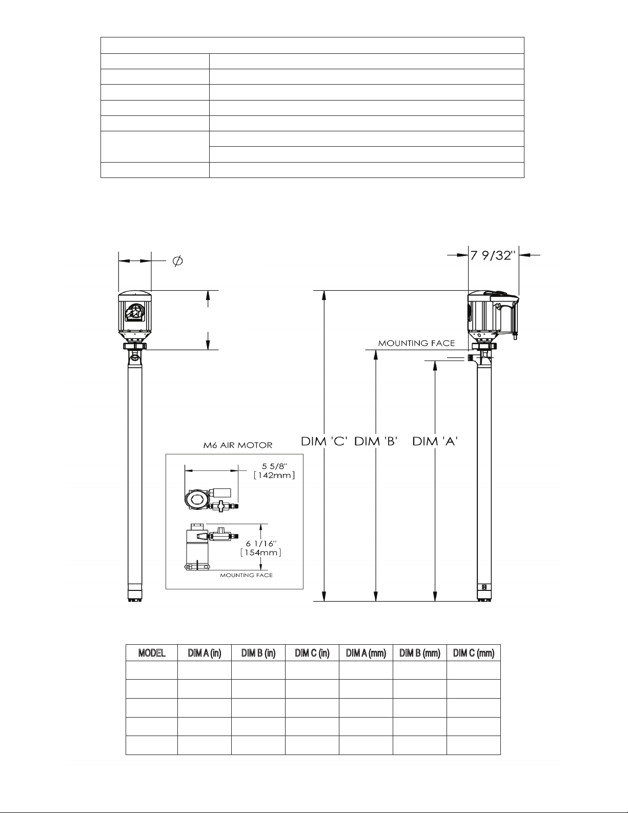
PUMP SPECIFICATIONS
Outer Tube Diameter 2” (51 mm)
Discharge Type 1” hose barb
Max. Specific Gravity 1.83
Max. Viscosity 500 cP
Min./ Max. Fluid
Temperature
Wetted Materials 316 Stainless Steel, Perlast, PTFE, ETFE
MODEL PFS ATEX
5°F Min. to 220°F Max.
21°C Min. to 105°C Max.
5-5/16”
12-11/32”
MODEL DIM A (in) DIM B (in) DIM C (in) DIM A (mm) DIM B (mm) DIM C (mm)
PFS-27 27 29 41-3/8 685.8 737 1050.9
PFS-40 40 42 54-3/8 1016 1067 1381.1
PFS-48 48 50 62-3/8 1219.2 1270 1584.3
PFS-60 60 62 74-3/8 1524 1575 1889.1
PFS-72 72 74 86-3/8 1828.8 1880 2193.9
4
Page 6
ATEX COMPLIANCE
The FTI PFS drum pump has been designed for use in hazardous environments. It meets the requirements set forth by EC directive
94/9/EC. This pump is designed to operate in zone 0 where explosive atmospheres are present. All three components (drum pump
tube, motor and Static Protection Kit) must be properly installed.
TEMPERATURE CLASSIFICATION
The surface temperature of the PFS pump depends upon the temperature of the fluid being pumped. Below is a chart showing the
temperature class that the pump falls in for various fluid temperatures, when used in locations where the ambient air temperature
is no greater than 104°F (40°C). The PFS, when used in hazardous locations, should only be used on products that allow for safe
operation within these classes.
Fluid
Temperature
Maximum
Surface Temperature
Temperature
Class
Maximum Allowable
Surface Temperature
75°F (24°C) 171°F (77°C) T5 212°F (100°C)
135°F (57°C) 185°F (85°C) T4 275°F (135°C)
190°F (88°C) 200°F (93°C) T4 275°F (135°C)
220°F (104°C) 208°F (97°C) T4 275°F (135°C)
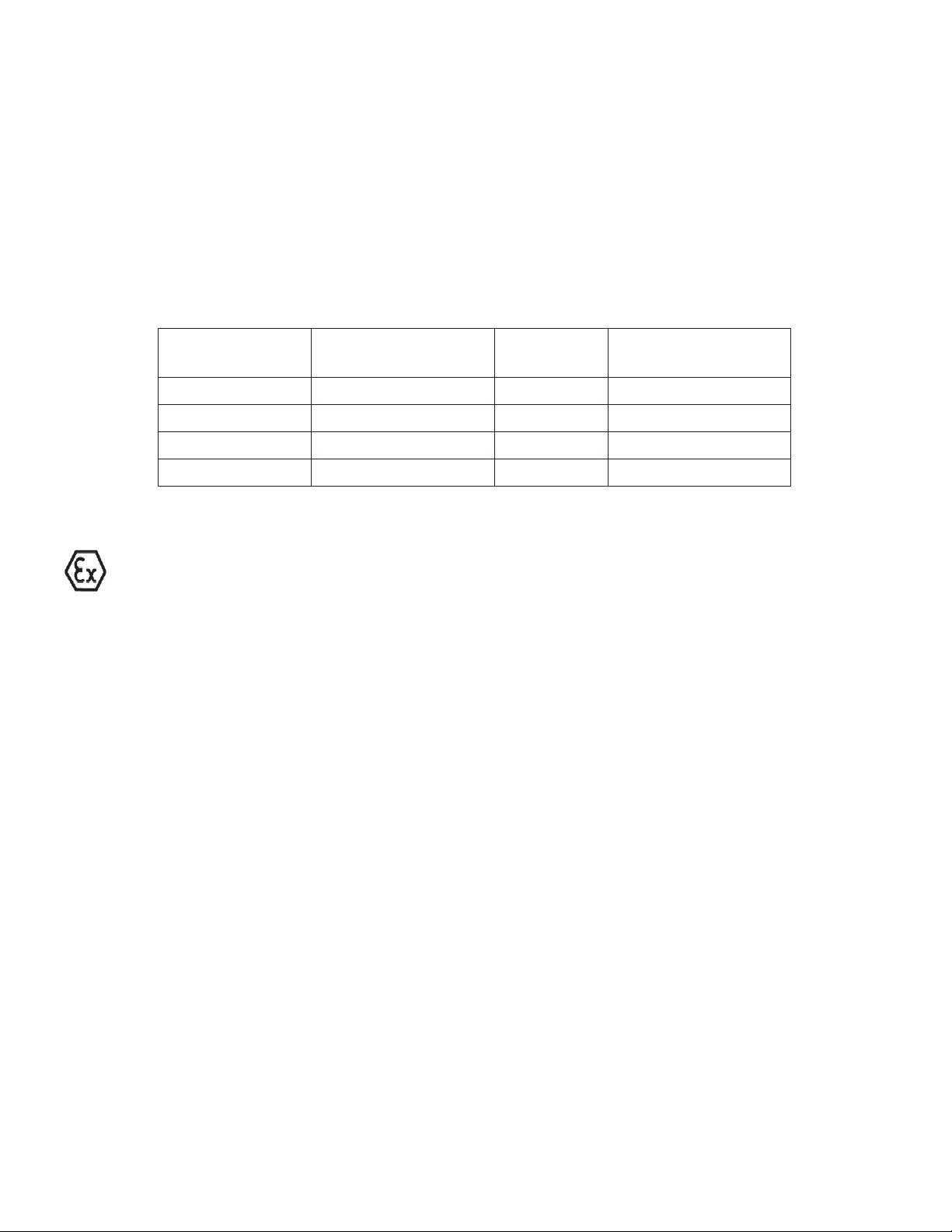
ATEX MOTOR INFORMATION
This symbol appears on labels of motors that are designed for use in hazardous atmospheres. These motors comply with
the applicable standards and specifications and meet the requirements of the guidelines of the EC directive 94/9EC (ATEX
100a). They are intended to be used in zones 1 and 2 where explosive atmospheres are likely to occur.
Complete the following checklist prior to starting installation in a hazardous area. All actions must be completed in accordance with ATEX 100a.
Checklist for installation in hazardous areas:
• Read motor label to check that motor has been designed for use in a hazardous application:
• Hazardous Zone
• Hazardous category
• Equipment group
• Temperature class
• Maximum surface temperatures
• Check the site environment for potentially explosive oils, acids, gases, vapors or radiation
• Check the site to make sure that the motor will be adequately ventilated and that there is no external heat
input. The cooling air may not exceed 104ºF/40ºC.
• Check that the motor is not damaged.
• Maximum motor surface temperature should not exceed 275ºF/135ºC based on ATEX temperature class T4
ambient range +1C° to + 40°C (34°F / 104°F).
5
Page 7

Installation, Assembly & Maintenance Instructions
PFS Installation
Installation
1. Remove the drum pump and motor from its packaging
and inspect for shipping damage.
2. Spin the pump coupling to verify there is no binding. Verify
that the black rubber coupling insert is firmly seated in the metal
pump coupling.
3. Verify that the housing cover (item 16) is on tight (it has left
hand threads).
4. Remove the (2) socket head screws and nuts from the motor/
motor mount.
5. Position the pump and motor couplings for proper alignment.
6. Slide the pump tube and motor together until the couplings
mate and are completely seated.
7. Install the (2) socket head screws and nuts and tighten securely.
8. Connect Static protection kit per diagram located below.
NOTE: When pumping flammable or combustible materials, DO NOT operate pump unless the static protection
kit is properly connected; otherwise, the pump/motor will not comply with ATEX requirements.
Static Protection Kit Assembly
Hose attachment to pump:
1. Place the stainless steel hose clamp onto the short section of the grounded hose.
2. Slide the short section of the grounded hose assembly over the pump tubes discharge spout. Tighten the
clamp.
3. Attach the ground wire assembly to the pump tube using the #8 ring terminal and supplied 8-32 x 1/4” brass
screw and brass lock washer.
4. Attach the ground wire assembly to the motor (see instructions below).
5. Check electrical continuity between the clamp on the end of the ground wire assembly and the end of the
grounded hose. The electrical resistance must be one (1) Ohm or less. If it is greater than one (1) Ohm, re-
check all connections.
6
Page 8

Ground wire attachment to motors:
Electric Explosion Proof:
1. Screw #10-32 plated nut onto exposed machine screw in motor housing.
2. Attach #10 ring terminal from the end of the ground wire assembly to exposed machine screw in motor
housing using #10-32 plated nut and #10 lock washer.
Air Motor:
1. Remove one of the Allen head set screws from the motor mount.
2. Slide the ¼-20 x 5/8” long round head machine screw through the 1/4” ring terminal on ground wire
assembly.
3. Thread ¼-20 plated nut onto the screw.
4. Insert the screw into the hole on the motor mount and tighten (do not over tighten).
5. Using a 7/16” wrench, tighten the ¼-20 nut against the ring terminal.
Drum Pump Installation
1. Install the pump and Static Protection Kit as described and shown in Figure 2.
2. Connect the ground wire assembly to an earth ground using the supplied clamp.
3. Connect the ground wire between the drum and the earth ground.
4. Connect the ground wire between the receiving container and earth ground (or use a bonding wire to
con nect to the drum).
5. Check electrical continuity of all components before pumping. All should be one (1) Ohm or less.
6. Avoid splashing when operating the pump. Splash filling can create static electricity.
PFS Maintenance
Disassembly
1. Remove the housing cover (item 16) by turning it clockwise (left hand thread) while gripping the impeller
housing (item 13).
2. Turn the impeller until a hole in the shaft can be seen through the square slot in the impeller housing (item
13), and insert 3/32 pin into the hole. Holding the pin, turn the impeller (item 15) counterclockwise (right-
hand thread) and remove it.
3. Remove the impeller housing (item 13) by gripping the intake tube and turning the housing clockwise
(left hand thread).
4. Place a wooden board or rubber mat on the floor (to protect the threads on the bottom of the shaft) and
gently tap the shaft (item 14) on it until the inner tube (item 9), shaft sleeve (item 10), and bottom bearing
(item 11) drops out. Continue to tap the shaft until both bearings (item 3) are exposed at the top of the
pump.
5. Pull the bearings and shaft out through the top of the pump.
7
Page 9

Inspection
1. Check the housing cover (item 16), the impeller (item 15), and the impeller housing (item 13) for wear, rubbing, or damage from foreign objects. Replace if damaged.
Note: The double impeller design of this pump is dependant on the impeller working correctly. Any damage
to the impeller can cause pump failure.
2. Inspect the pump shaft (item 14) for wear in the bottom bearing (item 11) and the lip seal (item 4) areas.
Replace the shaft if needed.
3. Inspect the bottom bearing (item 11) for internal wear. Inspect all o-rings (items 8 &12) for nicks or chemical attack. Replace as needed.
4. Inspect the bearing assembly (item 3) for rust or corrosion.
5. If the bearing assembly needs to be replaced, unthread it from the shaft. Insert 3/32” pin into the hole at
the bottom and hold the bearing assembly by the half coupling. Turn the shaft counterclockwise (right
hand thread) to loosen and remove. If corroded, then a penetrating fluid may be used on the threads to help
loosen.
Note: Never reuse the lip seal.
Reassembly
1. Install new lip seal (item 4) into the pump head with the grooved side facing the bottom of the pump.
2. If bearing assembly is replaced -- thread the shaft (item 14) into the bearing assembly (item 3) with the 3/32
hole in the shaft on the other end. Carefully insert the shaft straight through the lip seal (to avoid seal damage) from the top and seat the bearing assembly (item 3) into the pump head.
3. If o-rings are replaced -- install 2 inner tube o-rings (item 8) in the grooves. Install the impeller housing oring (item 12) inside the top of the housing. Apply a small amount of Vaseline to the o-rings to aid in assembly.
4. With the pump on a bench, slide shaft liner (item 10) into the inner tube (item 9) assembly onto the shaft
until it stops. Slide the shaft liner/inner tube/shaft assembly into the outer tube (item 7) using the shaft (item
14) as a guide.
5. Slide the impeller housing over the shaft, center the bottom of the lower inner tube into the counter bore in
the top of the impeller housing, and push / thread into the intake tube bottom (left hand thread).
6. Gripping the coupling at the top of the pump, thread the impeller on (right hand thread). Install the housing
cover (left hand thread). turn the coupling to verify there is no binding inside the pump.
8
Page 10

PFS ATEX SPARE PARTS EXPLODED VIEW
9
Page 11

PUMP SPARE PARTS LIST
ITEM QTY DESCRIPTION PART NUMBER
1 1
2 1
3* 1
4* 1
5 1
6 1
7 1
8* 2
9 1
10* 1
11* 1
12* 1
13 1
14 1
15* 1
16 1
*Recommended Spare Parts
COUPLING INSERT
J100014
COUPLING HALF
J100012
BEARING ASSEMBLY
A101110
LIP SEAL
1/4” 107622
LOCK WASHER
#8 BRASS J100823
SCREW
#8-32 X 1/4 BRASS PAN HEAD J100822
INTAKE TUBE ASSEMBLY
27” MODELS 107619-1
40” MODELS 107619-2
48” MODELS 107619-3
60” MODELS 107619-4
72” MODELS 107619-5
INNER TUBE O-RING
PERLAST 105620
STAINLESS STEEL INNER TUBE
27” MODELS 107616-1
40” MODELS 107616-2
48” MODELS 107616-3
60” MODELS 107616-4
72” MODELS 107616-5
PTFE SHAFT SLEEVE
27” MODELS 107615-1
40” MODELS 107615-2
48” MODELS 107615-3
60” MODELS 107615-4
72” MODELS 107615-5
BOTTOM BEARING
PTFE 108195
IMPELLER HOUSING O-RING
PERLAST 107621
IMPELLER HOUSING
Stainless steel **
SHAFT
27” MODELS M100004-5
40” MODELS M100004-3
48” MODELS M100004-4
60” MODELS M100004-12
72” MODELS M100004-13
IMPELLER ASSEMBLY
ETFE A100002-3
HOUSING COVER
STAINLESS STEEL **
**If either impeller housing or housing cover are being replaced, both must be ordered to ensure proper fit. Part number for housing cover and impeller kit is 108130.
10
Page 12

M6A AIR MOTOR SPARE PARTS LIST & VIEW
ITEM QTY DESCRIPTION PART NUMBER
1 1
2 1
3 1
4 1
5 1
6 1
7 2
8 1
9 2
10 2
11 1
12 1
13 2
14 1
Not shown: Air Motor Repair Kit J100060
AIR MOTOR
M101717
PIPE NIPPLE
J100107
HEX REDUCER BUSHING
J100057
BALL VALVE
J100073
HOSE FITTING
J100036
MUFFLER
J100033
SET SCREW
J100040
AIR MOTOR MOUNT
M100013-3
CAP SCREW
SOCKET HEAD J100023
NUT
HEX J100024
HALF COUPLING
A101621
LUBRICATOR
J100035
PIPE NIPPLE
J102463
FILTER
J100034
11
Page 13

M6XA AIR MOTOR SPARE PARTS LIST & VIEW
ITEM QTY DESCRIPTION PART NUMBER
1 1
2 1
3 1
4 1
5 1
6 2
7 1
8 2
9 2
10 1
11 1
12 2
13 1
Not shown: Air Motor Repair Kit J100075
AIR MOTOR
M101720
PIPE NIPPLE
J102463
BALL VALVE
J100073
HOSE FITTING
J100036
MUFFLER
J100074
SET SCREW
J100040
AIR MOTOR MOUNT
M100013-4
CAP SCREW
SOCKET HEAD J100023
NUT
HEX J100024
HALF COUPLING
A101620
LUBRICATOR
J100035
PIPE NIPPLE
J102463
FILTER
J100034
12
Page 14

M10X ELECTRIC MOTOR SPARE PARTS
The “M10X” Series motor housing repair kit number is A101455. Repairs to any item other than the thermoplastic enclosure
voids warranty.
Note: Motor housing repair kits include motor covers, labels and screws to repair the motor should it be damaged.
13
Page 15

Figure 1
Figure 2
Figure 3
Figure 4
Figure 5
Figure 6
M10X Switch Replacement Instructions
Warning: Motor is ATEX certified and repair work must be
performed by persons with competent electrical skills who are
familiar with ATEX regulations.
Warning: Make sure the machined aluminum surfaces of the
explosion proof housing are not scratched or damaged during
assembly/disassembly.
1. Remove the screws from plastic motor housing and strain relief connector.
See figure 1.
2. Carefully pry two plastic housings apart. The halves are sealed with two
beads of silicone caulking but will separate. Remove the aluminum motor
from the plastic housing.
3. Remove the screws from the top aluminum cover. See figure 2.
4. Pull the switch up from the slots in the motor housing and remove the
wires from the switch terminals. Note the wire locations. See figure 3.
5. Press wire terminals onto the terminals of the new switch making sure
they are in the correct location. When the letters “E-T-A” on one side of
the switch are facing up, the line connectors are on the right switch termi nals and the load connectors are on the left switch terminals.
6. Press the switch into slots of the aluminum housing. Make sure the letters
“E-T-A” on one side of the switch is facing up. The sides of the switch are
trimmed at the factory to fit the slot, slight additional trimming may be
required. See figure 4.
7. Replace the aluminum cover and install screws until they are tight.
8. Install a bead of silicone caulking in the center slot of each plastic motor
half. See figure 5.
9. Place the motor body in the slot of one plastic motor half and place the
other plastic motor half on top. See figure 6.
10. Reinstall all the screws. Plug in the motor and turn it on to verify proper
operation.
Page 16

FTZÚ, Pikartská 7, 716 07 Ostrava Radvanice, tel +420 596 232 715, fax +420 596 232 672, e-mail: ftzu@ftzu.cz
-Physical Technical Testing Institute
Ostrava-Radvanice
(1)
EC-Type Examination Certificate
(2)
Equipment or Protective Systems Intended for use
in Potentially Explosive Atmospheres
Directive 94/9/EC
(3) EC-Type Examination Certificate Number:
FTZÚ 04 ATEX 0293X
(4) Equipment or protective system: Drum pumps of type PFS ..
(5) Manufacturer : FINISH THOMPSON INC.
(6) Address: 921 Greengarden Road, Erie, PA 16501-1591, USA
(7) This equipment or protective system and any of acceptable variation thereto is specified in the
schedule to this certificate and the documents therein referred to.
(8) The Physical Technical Testing Institute, notified body number 1026 in accordance with Article 9
of the Council Directive 94/9/EC of 23 March 1994, cer tifies that this equipment or protective
system has been found to comply with the Essential Health and Sa fety Requirements relat ing to
the design and construction of equipment and protective systems intended for use in potentially
explosive atmospheres given in Annex II to the Directive.
The examination and test results are recorded in confidential Report N°
04/0293 dated 8 September 2004
(9) Compliance with Essential Health and safety requirements has been assured by compliance with:
EN 1127-1:1997 EN 13463-1:2001 EN 13463-5:2003
(10) If the sign „X“ is placed after the certificate number, it indicates that the equipment or protective
system is subject to special conditions for safe use specified in the schedule to this certificate.
(11) This EC-TYPE EXAMINATION CERTIFICATE relates only to the design, examination and testing
of the specified equipment or protective system in accordance to the directive 94/9/EC.
Further requirements of the Directive apply to the manufacturing process and supply of this
equipment or protective system. These are not covered by this certificate.
(12) The marking of the equipment or protective system shall include following:
II 1/2G c II C T5 .. T4
This EC-Type Examination Certificate is valid till:
Responsible person: Date of issue:11.09.2004
Dipl. Ing. Šindler Jaroslav Number of pages: 2
Head of certification body
This certificate is granted subject to the general conditions of the Physical Technical Testing Institute.
This certificate may only be reproduced in its entirety and without any change, schedule included.
Physical Technical Testing Institute
FTZÚ, Pikartská 7, 716 07 Ostrava Radvanice, tel +420 596 232 715, fax +420 596 232 672, e-mail: ftzu@ftzu.cz
Ostrava-Radvanice
(13)
Schedule
(14)
EC-Type Examination Certificate N° FTZÚ 04 ATEX 0293X
(15) Description of Equipment or Protective System:
A type PFS drum pump is used for transferring fluids from one contain er to another. There are five
different lengths available for the PFS pump and they are as follows : 68, 101, 122, 152 a 183
cm. Each pump has the same construction materials and design. The pump consists of a car bon
fiber filled impeller housed in a stainless steel impeller housing. A stainless steel shaft , is running
through the pump tube and is supported by two bushings, drives the impeller. PFS pump can
handle fluids up to 104°C ( 220 °F), and 330 cP. The pump is equipped by a static p rotection kit
to connect the pump to earth ground.
The pump may be equipped by following types of air motors:
Pneumatic drive
M6 M6X
300-6000 rpm 300-3000 rpm
0,37 kW 0,56 kW
II 2G c T5 II 2G c T5
(16) Report No. : 04/0293
(17) Special conditions for safe use:
Fluid temperature Temperature class
for ambient
temperature 40°C
up to 24 °C T5
up to 104 °C T4
(18) Essential Health and Safety Requirements:
Covered by standard mentioned in (9) of this certificate.
Responsible person: Date of issue:11.09.2004
Dipl. Ing. Šindler Jaroslav Number of pages: 2
Head of certification body
This certificate is granted subject to the general conditions of the Physical Technical Testing Institute.
This certificate may only be reproduced in its entirety and without any change, schedule included.
Physical Technical Testing Institute
14
Page 17

EC DECLARATION OF CONFORMITY
Finish Thompson Inc. hereby declares that the following machines fully comply with the applicable
health and safety requirements as specied by the EC Directives listed. This declaration is valid
provided that the devices are fully assembled and no modications are made to these machines.
Type of Device:
Drum or Container Pump
Pump Models:
PFS-27, PFS-40, PFS-48, PFS-60, PFS-72
EC Directives:
Equipment and protective systems intended for use in potentially
explosive atmospheres (94/9/EC)
EC-Type Examination:
Physical Technical testing Institute 1026
Ostrava-Radvanice
FTZU 04 ATEX 0293X
Product Quality Assurance Notication:
Physical Technical Testing Institute 1026
Ostrava-Radanice
FTZU 08 ATEX Q 003
Applicable Harmonized Standards:
EN 1127-1: 2011
EN 13463-1:2009
EN 13463-5:2011
Signed,
Casey D. Bowes
CEO and President
July 3, 2013
15
Page 18

EC DECLARATION OF CONFORMITY
Finish Thompson Inc. hereby declares that the following machines fully comply with the applicable
health and safety requirements as specied by the EC Directives listed. This declaration is valid
provided that the devices are fully assembled and no modications are made to these machines.
Type of Device:
Pump Motor
Pump Motor Models:
M10X
EC Directives:
Equipment and protective systems intended for use in potentially
explosive atmospheres (94/9/EC)
EC-Type Examination:
Physical Technical Testing Institute 1026
Ostrava-Radvanice
FTZU 08 ATEX 0083X
Product Quality Assurance Notication:
Physical Technical Testing Institute 1026
Ostrava-Radanice
FTZU 08 ATEX Q 003
Applicable Harmonized Standards:
EN 60079-0:2012
EN 60079-1:2007
Signed,
Casey D. Bowes
CEO and President
July 3, 2013
Page 19

EC DECLARATION OF CONFORMITY
Finish Thompson Inc. hereby declares that the following machines fully comply with the
applicablehealthandsafetyrequirementsasspeciedbytheECDirecveslisted:
TypeofDevice:
Pump Motor
PumpMotorModels:
M6A, M6XA
ECDirecves:
EquipmentandProtecveSystemsIntendedForUseInPotenally
ExplosiveAtmospheres(94/9/EC)
ApplicableHarmonizedStandards:
DINEN1127-1:2011
DINEN13463-1:2099
DINEN13463-5:2011
Theproductsaremarkedwiththefollowingcharacteriscs:
II2GDc+1oCTa+40oC
DocumentaonarchivedinFTZÚOstravaRadviance,ECcode1026
Thisdeclaraonisvalidprovidedthatthedevicesarefullyassembledandnomodicaons
are made to these machines.
CaseyD.Bowes
CEOandPresident
May1,2012
Service 1-800-888-3743
P/N 105619 Rev. 11, 7/17/13
 Loading...