

Page 1
MSVKC SERIES
Sealless Non-Metallic Vertical Pumps
Installation and Maintenance Instructions
Pat. No. 5,708,313
ASSEMBLY
WARNING: Magnetic field hazard. This pump contains powerful rare
earth magnets. When the pump is disassembled (not connected to a
motor) and the magnets are exposed, these magnets produce powerful magnetic fields. Individuals with cardiac pacemakers, implanted
defibrillators, other electronic medical devices, metallic prosthetic
heart valves, internal wound clips (from surgery), metallic prosthetic
devices or sickle cell anemia must not handle or be in the proximity of
the magnets contained inside the pump. Consult a health care provider
for specific recommendations before working with this pump.
PUMPS WITH MOTORS
1. No assembly required. Simply unpack the pump and motor and examine
for any signs of shipping damage. If damage is detected, save the
packaging and notify the carrier immediately.
2. Ensure that lock rings are securely snapped in place and did not loosen
during shipment.
3. To install the pump into the system, follow the installation instructions
provided.
PUMPS WITHOUT MOTORS
Note: Finish Thompson has added extra weight (Flywheel item 35 in Figure
5) to several of our MSVKC Series Pumps to slow down motor start
up & prevent possible magnet decoupling. It is necessary to know
whether your pump was supplied with the flywheel. Flywheels are
supplied with all 56C NEMA & 80 Metric frame motor adapters. If you
are unsure whether your pump was supplied with a flywheel, please
contact FTI’s Tech Service Department at PH: 800-888-3743 or email
techservice@finishthompson.com.
Note: Motor assembly videos are available online at www.finishthompson.com/downloads/maintenance videos.
CAUTION: Pump assembly may be top heavy.
6. Rotate the pump and the mounting plate if ordered to the desired orientation. Align the holes in the mounting plate and the motor adapter
with the holes in the motor face. Secure the mounting plate and motor
adapter to the motor using the correct bolts and washers (items 6,7,
and 8) from the hardware package.
7. Check and verify the locking rings are securely snapped in place and
did not loosen during shipping. Rotate the motor fan to check for binding
or rubbing inside the pump.
8. Install the pump into the system according to the installation instructions provided.
FOR 63, 71 METRIC FRAME ADAPTERS WITHOUT FLYWHEEL (USE
FIGURE 6):
1. Unpack the pump and any supplied accessories and examine for
damage. If any damage is detected, save the packaging and notify
the carrier immediately.
2. Prepare to assemble the pump onto the motor by placing the motor
on the fan cover on a suitable clean, level work surface.
3. Install the keyway into the motor shaft key slot. Align the keyway slot
in the coupling half (item 29, figure 6), and slide the coupling half onto
the motor shaft with the splined side facing the pump. Set the coupling
half with the motor shaft recessed 11.1 mm. Tighten both setscrews
with a 1/8” Allen wrench to 7.9 N-m.
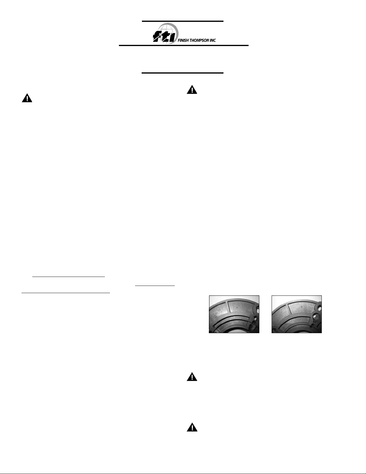
4. Install the metric motor adapter (item 2 in figure 6) onto the motor. To
aid in correct installation, the letters “A” & “B” are molded onto the
opposite sides of the motor adapter. For 71 frame motors, using the
correct hardware (items 3,4 and 5 in figure 6) mount the adapter with
side “B” facing up. For 63 frame motors, using the correct hardware
(items 3,4 and 5 in figure 6) mount the adapter with side “A” facing
up. See figures A & B.
FOR 56C FRAME ADAPTERS WITH FLYWHEEL (ITEM 35 IN FIGURE 5):
1. Unpack the pump and any supplied accessories. Examine for shipping
damage. If damage is detected, save the packaging and notify the
carrier immediately.
2. Prepare to assemble the pump onto the motor by placing the motor
on the fan cover on a suitable clean, level work surface.
3. Install motor key into motor shaft key slot. Align the keyway slot on
the flywheel (item 35 in figure 5) and slide the flywheel onto the motor shaft with the protruding boss towards the motor face. Align the
keyway slot in the top coupling half (item 29 in figure 5) and slide the
coupling half on. Set coupling half with the motor shaft recessed 7/32”
and tighten both setscrews with a 1/8” Allen wrench to 70 in-lbs.
4. Slide the flywheel forward so that it rests against the backside of the
coupling half. Tighten both setscrews.
5. Install the coupling insert (yellow internally splined plastic ring) onto
the coupling half on the motor shaft. Place coupling support (item
38A in figure 5) into center of coupling half with the short side facing
the motor. Carefully slide the motor adapter end (item 9 in figure 5)
of the pump assembly over the motor shaft until both coupling halves
are completely seated in the coupling insert. Make sure rabbet on the
motor is firmly seated into the motor adapter.
5. Install the coupling insert (yellow internally splined plastic sleeve) onto
the coupling half on the motor shaft. Carefully slide the motor adapter
(item 9 in figure 6) onto the motor making sure the pump shaft coupling
matches up with the plastic insert and seats properly. Make sure rabbet
on the motor is firmly seated into the motor adapter.
CAUTION: Improper positioning of the metric motor adapter can
cause premature coupling failure or cause the pump shaft to bottom
out before the pump is properly installed onto the motor adapter.
6. Rotate the pump discharge and the mounting plate if ordered to the
desired orientation. Align the bolt holes on the mounting plate with
the motor adapter (item 9 in figure 6) and the metric motor adapter
flange (item 2 in figure 6). Secure with the hardware provided.
CAUTION: Pump assembly may be top heavy.
7. Check and verify the locking rings are securely snapped into place and
did not loosen during the assembly process. Rotate the motor fan to
check for binding or rubbing inside the pump.
1
Figure A Figure B
Page 2
8. Install the pump into the system according to the installation instructions provided.
FOR 80 FRAME METRIC MOTOR ADAPTER WITH FLYWHEEL (ITEM 35
IN FIGURE 5):
1. Unpack the pump parts and any supplied accessories and examine
for damage. If damage is detected, save the packaging and notify
the carrier immediately.
2. Prepare to assemble the pump onto the motor by placing the motor
on the fan cover on a suitable clean, level work surface.
3. Install the keyway into motor shaft key slot. Align the keyway slot in
flywheel adapter / coupling half combination (item 34 and metal half
of item 29 in figure 5) and install on motor shaft with splined side
facing the pump. Note: these items are pre-assembled at the factory.
Set coupling half flush with the end of the motor shaft and secure with
coupling support washer, lock washer and bolt (items 38B, 39 & 40
in figure 5). Tighten both setscrews in coupling half with 1/8” Allen
wrench to 7.9 N-m.
4. Install the metric motor adapter (item 2 in figure 5) onto the motor. To
aid in correct installation, the letters “A” and “B” are molded on the
opposite sides of the metric motor adapter. For 80 frame motors using
the correct hardware (items 3,4 and 5 in figure 5) mount the adapter
with side “A” facing up. The metric motor adapter must be positioned
so that the adapter seats onto the motor rabbet. See figures A & B
above.
CAUTION: Improper positioning of the metric motor adapter can
cause premature coupling failure or cause the pump shaft to bottom
out before the pump is properly installed onto the motor adapter.
5. Install the flywheel (item 35 in figure 5) onto the flywheel adapter and
attach using four screws with lock washers (items 36 and 37 in figure
5). Tighten securely.
6. Insert the coupling insert (yellow internally splined plastic sleeve) into
the coupling half on the motor. Carefully slide the motor adapter end
(item 9 in figure 5) of the pump assembly over the motor shaft until
both coupling halves are completely seated in the coupling insert.
Make sure rabbet on the motor is firmly seated into the motor adapter.
7. Rotate the pump discharge and mounting plate if ordered to the desired
orientation. Align the bolt holes on the mounting plate with the motor
adapter (item 9) and the metric motor adapter flange (item 2). Secure
with the hardware provided.
8. Make sure that the locking rings are securely snapped in place and
did not loosen during shipping or the assembly process.
CAUTION: Pump assembly may be top heavy.
Install the pump into the system according to the installation instructions
provided.
INSTALLATION
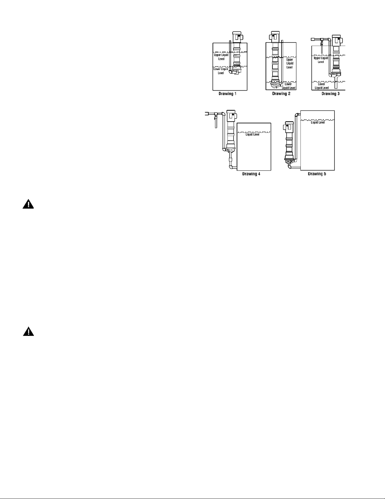
The VKC Series is a versatile pump designed to be operated in a variety
of mounting configurations. The pump can be mounted either inside or
outside of a tank or sump. See Figure 1.
Note: Drawings for illustration only. Pumps need to be properly supported when installed.
drawings 3 and 4 in Figure 1.
Figure 1
Drawing 1 shows drawing of pump mounted inside a tank with suction off the bottom of the tank
and level fluctuating from near top of pump column to close to the bottom of the pump.
Drawing 2 shows drawing of pump suction near tank bottom and level fluctuating between the
top and bottom of the tank.
Drawing 3 shows drawing of pump with suction extension and the level fluctuating between
startup level and low level.
Drawing 4 shows drawing of pump mounted outside the tank.
Drawing 5 shows drawing of pump mounted outside the tank with the motor below the liquid level.
MOUNTING
A mounting plate is recommended for in-tank installations. Use a hole
saw to cut holes in desired location for piping if required.
Support and securely fasten the mounting plate on all four sides if
possible or on two sides if mounted in a corner. Drill holes in the
mounting plate at the desired location for bolting to the tank.
A drip cover may be installed on top of the motor if desired.
Mount pump in desired configuration. Securely fasten mounting
plate if used. Motor feet may also be used for mounting.
PIPING
1. Support piping near the pump to eliminate any strain on the pump
casings. Do not use suction or discharge piping to support the pump.
2. Do not overtighten the piping on the discharge on initial installation
(i.e., down to the O-ring). Damage to the discharge can occur. The
O-ring is used only when there is wear and the plastic threads are
loose.
3. Do not place the pump suction directly on the bottom of the tank. Keep
the pump suction at least one pipe diameter off the bottom.
4. A suction extension tube of up to nine feet in length can be added.
5. To minimize head loss from friction:
a. Increase pipe size by 1 diameter.
b. Use minimal number of pipe bends.
6. If a check valve is installed in the discharge piping, an air bleed must
be installed in the discharge line to prevent air lock. This allows air
trapped in the pump internals to be removed on initial startup. See
2
Page 3
7. Maintain a flooded suction. Use a foot valve if necessary.
8. Ensure that the piping does not leak and suction is not prone to clogging. Use a strainer if necessary on the suction.
9. If flexible hose is preferred, use reinforced hose rated for the proper
temperature and pressure. This helps avoid collapse or kinks.
10. Install valves a minimum of 10 pipe diameters from the pump.
CAUTION: To stop the pump if prime is lost, use one of the following:
(1) pressure switch on the discharge or (2) motor minder to monitor motor
current.
ELECTRICAL
Install motor according to NEC requirements and local electrical codes.
Motor should have an overload protection circuit.
Important. To verify the correct motor rotation:
1. Install the pump into the system.
2. Fully open suction and discharge valves.
3. Allow fluid to flow into the pump. Do not allow the pump to run dry
(PTFE & ceramic bushings can not be allowed to run dry
without damage to pump components).
4. Jog the motor (allow it to run for one to two seconds) and observe
rotation of the motor fan. Refer to directional arrow on the pump.
Note: A pump running backwards will pump but at a greatly
reduced flow and pressure.
OPERATION
1. Completely open the discharge valve. On pumps equipped with a
discharge check valve, open air bleed valve on initial startup.
2. Start the pump and check liquid flow. If there is no flow, see the
Troubleshooting section.
3. Adjust the flow rate and pressure by regulating the discharge valve.
MAINTENANCE
DISASSEMBLY
1. Disconnect the power and remove the wiring.
2. Close the discharge valve and disconnect the piping.
3. Remove the mounting bolts and pull the pump from the tank. Securely
anchor or clamp the motor to a workbench in a horizontal position.
4. Gently tap the locking ring (item 11 closest to pump end) toward the
motor until it is loose. Mark a matching line on the barrier/column
housing adapter (item 16) and the 2nd stage impeller housing (item
20) as a discharge orientation reference during re-assembly. Using a
strap wrench on the barrier/column housing adapter (item 16), turn
it counterclockwise and remove it from the pump column. When it is
unthreaded, pull it straight off to expose the drive magnet assembly
(item 14).
5. Place the pump end / barrier column housing adapter on a clean work
surface with the suction pointing straight up. Remove the six screws
and washers (items 25A,B, & C) from the impeller housing.
6. Using a thin bladed screwdriver, gently separate the 1st stage housing
(item 24) from the diffuser (item 22). Remove the 1st stage impeller
housing (item 24) being careful to pull straight off so as not to damage
the ceramic front spindle support. Remove the housing O-ring (item
17). Holding down on the outside of the diffuser assembly (item 22)
with one hand, gently pull the 1st stage impeller/impeller drive shaft
assembly (items 19 & 23) from the pump.
7. Remove the diffuser assembly (item 22) and the diffuser O-ring (item
21) from the top of the 2nd stage impeller housing (item 20). Remove
the 2nd stage impeller housing (item 20), the housing O-ring (item 17),
and the 2nd stage impeller assembly (items 18 & 19) from the barrier/
column-housing adapter (item 16).
8. If further disassembly is required, place a 9/16-inch wrench on the flat
area of the pump shaft (item 13) on the motor side of the drive magnet
assembly (item 14).
Holding the pump shaft with the wrench, remove the locking nut (item
15) by turning it clockwise (left hand thread). After the nut is removed,
unthread the drive magnet assembly (item 14).
9. If the pump is longer than 12 inches, you remove each of the column
extensions (item 30) by doing the following. Loosen the two set screws
on the shaft bearing (item 31), gently tap the locking ring (item 11)
toward the motor, and use the strap wrench to unthread the section.
10. When you are down to the motor adapter (item 9), mark a matching
line on the adapter flange, mounting plate (item 10), and the motor to
be referenced during reassembly. Loosen the setscrews on the shaft
bearing (item 31). Remove the 4 motor adapter bolts and washers (items
6, 7, & 8), the mounting plate (item 10), the motor adapter (item 9), and
the metric motor adapter (item 2) if required. If motor is to be replaced,
remove the coupling insert and coupling half (part of item 29).
CAUTION: Keep the drive magnet assembly and the impeller drives
away from metal chips or particles
EXAMINATION/REPLACEMENT OF PARTS
1. Inspect the bushings (items 18A) in both the impeller drive (item 18) and
the impeller drive shaft (item 23). See figure 2. If bushing in impeller
drive (item 18) requires replacement, grip the impeller assembly (items
18 & 19) with the bushing side up, and gently tap the impeller (item
19) off the impeller drive (item 18). Insert a 1/16-inch punch into the
balance hole (inner circle of four holes) on top of the impeller drive (item
18) and gently tap out the bushing. The punch may need to be moved
to a second hole to complete the removal. Install the new bushing by
gently pressing it in until it bottoms out (use a block of wood and a
mallet if necessary). If the bushing in the impeller drive shaft is worn
or cracked, the complete impeller drive shaft with bushing (item 23)
needs to be replaced.
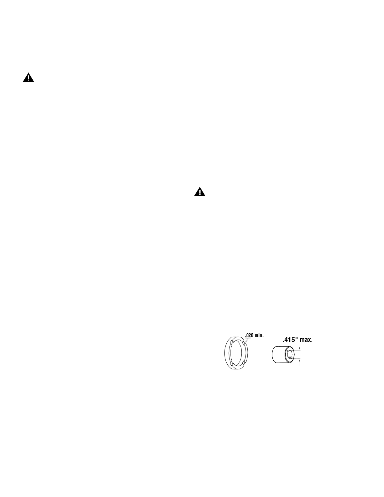
2. Inspect both thrust rings (item 19A) for wear. See figure 2. If replacement is necessary pull the old ring out, align the flat on the new ring
and the seating area and press into place.
Figure 2
3. Inspect both ceramic housing thrust rings and both the barrier ceramic
post and the 1st stage impeller housing ceramic support post for cracks,
chips, scoring, or excessive wear. Replace as required.
4. Check for loose magnets on the drive hub (item 14) or rubbed areas on
the barrier/column housing adapter (item 16) or impeller assemblies.
Contact your distributor or FTI Technical Service if a problem is found.
5. Inspect the bearing(s) for damage and replace if necessary. To remove
the bearing, unscrew the four retaining screws (item 32) and press
the bearing out (note: the top of the bearing where the set screws are
faces away from the motor). Installation of the new bearing requires
pressing it into the section with the set screws/collar facing away from
the motor, and replacing the retaining screws.
6. Examine all the plastic parts for damage or wear. Replace as needed.
3
Page 4
7. Examine all of the o-rings for nicks or chemical attack and replace as
needed.
8. If the motor requires replacement, loosen the set screws and remove
the coupling half (part of item 29) from the motor shaft.
REASSEMBLY
1. If the motor was replaced-
Slide the coupling half (half of #29) on to the motor shaft with the
splines facing away from the motor. On 56C motors, set coupling half
so that motor shaft is recessed 7/32”.
For 63 and 71 frame motors, set coupling half so that motor shaft is
recessed 7/16”, and on 80 frame motors set coupling half so that it
is flush with the motor shaft.
2. On 56C, 63, & 80 frame motors, align one set screw with flat or key slot
on motor shaft and tighten both set screws with a 1/8” Allen wrench
to 70 in.-lbs. (7.9 N-m). For 71 frame motors, align both set screws 90
degrees from motor flat or key slot and tighten as instructed above.
3. If the shaft was replaced, slide the second coupling half onto the pump
shaft (the end with the milled flat) with the splined side facing away
from the threaded end of the shaft. For 56C motor frames, set the
coupling with the pump shaft recessed 7/32”. For 63 and 71 motor
frames, set it with the pump shaft recessed 7/16”. For 80 frame, the
pump shaft should be recessed ¼”. When coupling half is set correctly,
align set screw with the flat on the pump shaft, and tighten both set
screws with 1/8”allen wrench to 70 in.-lbs. (7.9 N-m).
4. Place the motor gently on the fan cover for reassembly. For metric
frame pumps, install the metric motor adapter flange (item 2) onto
the motor with the correct hardware (items 3, 4, & 5). One side of
the adapter fits 63 & 80 frame motors (side B) and the other side fits
the 71 frame motors (side A). The letters A & B are molded onto the
adapter. For 71 frame motors the “A” must face the motor, and for
63 & 80 frame motors the “B” must face the motor. The metric motor
adapter must be oriented so that the adapter seats completely onto
the motor rabbet. Make sure your orientation marks are aligned (step
10 of disassembly instructions).
CAUTION: Improper orientation of the metric motor adapter can cause
premature coupling failure or cause the pump shaft to bottom out on
the motor shaft before
5. Install the coupling insert (center plastic part of item 29) onto the
coupling half on the motor. Now insert the pump shaft with coupling
half into the coupling insert until it is completely seated.
6. Locating the pump shaft through the bearing in the motor adapter
section (item 9) carefully slide the motor adapter (item 9) down the
shaft until it is fully seated on the (56C) motor rabbet or (63, 71, 80
frame) on the metric motor adapter. If a mounting plate (item 10) is
being used, gently slide it over the pump shaft and the motor adapter
section (item 9).
7. Rotate the mounting plate and the motor adapter to the desired
orientation (marked before disassembly), and align the holes through
the mounting plate, motor adapter and into the motor (metric motor
adapter if used). Secure the mounting plate and the adapter to the
motor (item 1)/metric adapter (item 2) using the correct hardware
(items 6, 7, & 8 for 56C or item 33 for metric).
8. Tap down gently with a rubber mallet on the top of the pump shaft
to ensure compete coupling engagement. Tighten both bearing set
screws onto the pump shaft using a 3/32” Allen wrench. Replace if
needed and lubricate the two motor adapter/ column extensions o-rings
(item 12) with a chemically compatible thread lubricant.
9. For 12” pumps, go to step 10. For 18” or longer pumps, slide the lock
ring (item 11) past the corresponding flats toward the motor. Make
sure to place the smaller inside diameter side of the lock ring toward
the motor. Use a chemically compatible thread lubricant to lubricate the
external plastic threads on the motor adapter (item 9) and the internal
plastic threads on the column extension (item 30). Gently slide the
column extension with bearing onto the pump shaft. Install if needed
and lubricatethe two column extension o-rings (item 12). Repeat step
9 for each column extension to be installed.
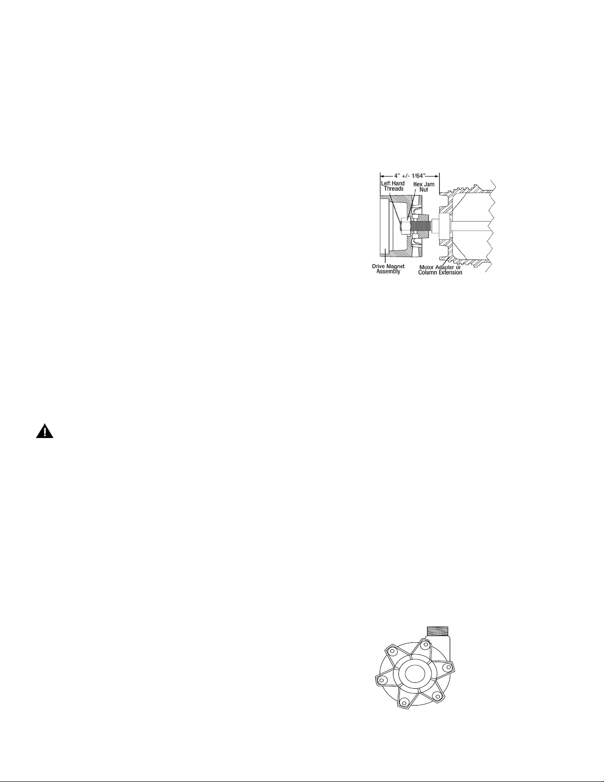
10. Thread the left hand threaded drive magnet assembly (item 14) onto
the pump shaft until it is 4” +/- 1/64” as measured from the top of
the drive magnet assembly as shown in Figure 3. A 9/16” wrench can
be used on the milled flats below the threads to hold the pump shaft
during this step. Apply a small amunt of Loctite Thread Locker 262
to the left-hand threaded 5/8-18 hex jam nut (item 15) and thread
onto the pump shaft. Tighten to 50 ft. lbs. Recheck the drive setting
dimension after the nut is tightened.
Figure 3
11. Place the barrier/housing adapter on a clean surface with the white
ceramic post facing up. Place the impeller drive assembly (items 18
and 19) onto the ceramic post. Install and lubricate (with a chemically
compatitible lubricant) the housing o-ring (item 17).
12. Noting the reference marks made during disassembly on the impeller
housing and the barrier column assembly, align the bolt hole tabs and
snap the housing in place (bolt hole alignment is critical).
13. Install and lubricate the diffuser o-ring (item 21). Install the diffuser
assembly (item 22) being careful not to dislodge the o-ring and to keep
the bolt hole alignment straight.
14. If the impeller drive shaft (item 23) was replaced, reassemble it onto
the impeller assembly (item 19) by matching the three tabs on the end
of the drive shaft with the three recessed slots in the impeller assembly
and pressing together.
15. Looking through the hole in the center of the diffuser assembly, note
the orientatin of the square recess in the top of the first stage impeller
drive (item 18). Insert the square end of the drive shaft through the
hole in the diffuser and into the square recess in the impeller driive.
Press gently but firmly to seat the drive shaft.
16. Install and lubricate the housing o-ring (item 17) onto the diffuser (item
22). Lower the first stage impeller housing (item 24) straight down
onto the pump with the ceramic front spindle support sliding into the
bushing (item 18A) on top of the first stage impeller assembly. Orient
the housing with the direction arrow on top (same as discharge direction), the drain boss on the bottom, andwith the mounting holes aligned.
Install the mounting bolts and hardware (items 25A, B & C) making
sure not to dislodge the housing o-ring (item 17) or the diffuser o-ring
(item 21). Hand tighten the mounting bolts to pull the pump together
using the pattern shown in Figure 4.
3
1
5
Figure 4
6
2
4
Note: It is not recommended to reuse plastic screws. Always use
thread lubricant when installing plastic screws.
4
Page 5

17. After the housing is secure, insert a screw driver into the suction
and push down on the front of the first stage impeller assembly to
completely seat the drive shaft (item 23) into the 2nd stage impeller
(item 18). Push firmly on all three areas separated by the front spindle
support in the suction.
CAUTION: Do not press on the gray thrust ring.
18. Slide the lock ring (item 11) over the drive magnet assembly and past
the corresponding flats on the column extension (motor adapter if 12”
pump) making sure the smaller inside diameter side is toward the
motor. Lubricate the external threads on the column extension (motor
adapter on 12” models), the o-rings, and the internal threads on the
barrier column section. Gripping the assembled pump end firmly, slide
it down over the drive hub until the threads touch, and screw the pump
end onto the column section. Use a strap wrench to tighten until there
is no gap between the sections and the flats are parallel. Pull the lock
ring up. Match with corresponding flats and snap into place.
CAUTION: Do not allow your fingers to get between the drive hub and
the barrier column section during assembly.
19. Rotate the motor fan and listen/feel for drive hub rubbing (recheck
drive hub setting) or the first stage impeller (item 19) rubbing on the
housing (recheck step 17).
20. Reinstall the pump into the system according to the installation instructions.
GENERAL NOTES
1. Do not pump liquids containing metal fines.
2. If magnets decouple, stop the pump immediately. The rare earth magnets
used in this pump are more resistant to demagnetization, but operating the
pump with the magnets decoupled will eventually weaken the magnets.
3. Plastic pumps will expand and contract with temperature so periodically
check and hand tighten screws.
4. Use a chemically compatible thread lubricant on threads of column sections.
5. The setting of the drive magnet dimension is critical. Failure to properly set
the dimension may result in decoupling or damage to pump components.
6. An information sticker is attached to the motor adapter section or the
mounting plate. The first line is the model number, and the second line
is the serial number.
7. The pump will contain various numbers of shaft bearings (item 28)
based on the length of the pump as follows:
18” pump = (1) shaft bearings
24” pump = (2) shaft bearings
30” pump = (3) shaft bearings
36” pump = (4) shaft bearings
42” pump = (5) shaft bearings
48” pump = (6) shaft bearings
54” pump = (7) shaft bearings
60” pump = (8) shaft bearings
8. Due to the hermetically sealed design, the pump will displace liquid
as follows:
18” pump = approximately 1-1/4 gallons (4.73 liters)
Add approximately 1 quart (.95 liter) per column section.
E.G. 24” pump = 1-1/2 gallons (5.68 liters)
9. 18” pumps do not have column extensions.
10. Largest diameter impeller is always closest to motor.
5
Page 6

Figure 5
MSVKC with Flywheel
56C and 80 Frame Metric Motors
Spare Parts Drawing
1
34
For 80 frame
only
For 80 frame
only
35
37
36
38A
2
3
4
5
9
41
32
13
14
10
6
7
8
11
For 80 frame only
29
33
38B
For 80 frame
39
40
31
15
19
only
R100581
16
17
18A
18
24
19A
17
19A
20
21
22
23
18A
19
25A
25B
25C
6
Page 7

41
32
Figure 6
MSVKC Without Flywheel
63 and 71 Frame Metric Motors
Spare Parts Drawing
1
2
3
4
5
9
13
14
10
29
33
31
15
6
7
8
11
16
19
17
18A
18
19A
17
24
19A
20
21
22
23
18A
19
25A
25B
25C
R100581
7
Page 8

MSVKC SPARE PARTS
Item Description Frame
1 Motor 56C, 71, 80 AS LISTED
2 Metric Motor Adapter
3 1/4” Flat Washer All metric J100113
4 1/4” Lock Washer All metric J100672
5 Socket Head Screw 71/80 J103228
6 3/8” Flat Washer SSTL All J100128
7 3/8” Lock Washer SSTL All J100115
Motor Mounting Bolts 3/8-16 x 1 3/4" Hex Hd. Cap Screw 56C J103161
Motor Mounting Bolts 3/8-16 x 1" Hex Hd. Cap Screw 56C J100114
8
Motor Mounting Bolts 3/8-16 x 2 1/4" Hex Hd. Cap Screw 71/80 J103227
Motor Mounting Bolts 3/8-16 x 1 1/2" Hex Hd. Cap Screw 71/80 J103207
9 Motor Adapter All M101981-1 M101981-2
Mounting Plate - PVC - 9 1/2" x 14" x 3/4" (optional) All 105611
10
Mounting Plate - CPVC - 91/2” X 14” X 3/4” (optional) 105611-1
11 Lock Ring M101984-1 M101984-2
Motor Adapter/Column Ext. O-ring
Viton J103306
12
EPDM J103308
Shaft
18” 56C M102119-9
18” 80 M102119-19
18” 71 M102119-10
24” 56C M102119-1
24” 80 M102119-20
24” 71 M102119-5
30” 56C M102119-2
30” 80 M102119-21
30” 71 M102119-6
36” 56C M102119-3
36” 80 M102119-22
36” 71 M102119-7
42” 56C M102119-4
13
42” 80 M102119-23
42” 71 M102119-8
48” 56C M102119-11
48” 80 M102119-24
48” 71 M102119-15
54” 56C M102119-12
54” 80 M102119-25
54” 71 M102119-16
60” 56C M102119-13
60” 80 M102119-26
60” 71 M102119-17
66” 56C M102119-14
66” 80 M102119-27
66” 71 M102119-18
Drive Mag Assembly All A101989-20
14
15 Jam Nut (left hand thread) All J103515
16 Barrier/Column Hsg. Adapter All A102271-1 A102271-2
Impeller Housing O-ring
Viton
17
EPDM J102585
Impeller Drive
with Carbon Bushing
18
with PTFE Bushing A103269-2 A103269-5
with Ceramic Bushing A103269-3 A103269-6
Impeller Bushing
18A
Carbon
PTFE J102790
Ceramic J103617
63, 71 M101947
80 M101947-2
All
All
All
Polypropylene PVDF
A103269-1 A103269-4
Part Number
J102389
J102387
8
Page 9

Item Description Frame
Impeller with Thrust Ring
3.00”
19
3.19” A101983-15 A101983-16
3.50” A101983-2 A101983-5
3.88” A101983-3 A101983-6
Thrust Ring - PTFE
3.00”/3.19”
19A
3.50”/3.88” J101606
Impeller Housing - 2nd Stage NPT A103205-1 A103205-2
20
Impeller Housing - 2nd Stage - with Viton® Discharge O-ring BSP A103271-1 A103271-2
Impeller Housing - 2nd stage - EPDM Discharge O-ring BSP A103271-3 A103271-4
Diffuser O-ring - Viton
21
Diffuser O-ring - EPDM J102446
22 Diffuser Assembly All Contact FTI with pump serial number.
Impeller Drive Shaft w/Carbon Bushing
23
Impeller Drive Shaft w/PTFE Bushing A103270-2 A103270-5
Impeller Drive Shaft w/Ceramic Bushing A103270-3 A103270-6
24 Impeller Housing - 1st Stage
5/16 Flat Washer
25A
Titanium
Hastelloy J103846
5/16 Lock Washer
25B
Titanium
Hastelloy J103848
C/S Hex Head 5/16-18 x 5-1/4” lg.
Titanium
25C
Hastelloy J103925 J103925
PVDF J103926 J103926
26 Hex reducer Bushing 1-1/2” x 1” All J103160 J103159
27 Elbow - 90o x 1-1/2” All J103165 J103166
Discharge Pipe
18” pump length
24” pump length M101965-7 M101965-8
30” pump length M101965-3 M101965-4
36” pump length M101965-9 M101965-10
28
42” pump length M101965-5 M101965-6
48” pump length M101965-11 M101965-12
54” pump length M101965-13 M101965-14
60” pump length M101965-15 M101965-16
66” pump length M101965-17 M101965-18
29 Coupling
30 Column Extension All M101982-1 M101982-2
31 Shaft Bearing All J103157
32 Bearing Retaining Screw All J103175
33 3/8-16 Hex Nut (for metric motor adapter) All J100135
34 Flywheel Adapter 80 105442
35 Flywheel
36 Socket Head Bolts 80 J100023
37 Lock Washer 80 J103637
38A Coupling Support 56C 105463
38B Coupling Support 80 105444
39 Lock Washer 80 J100672
40 Hex Head Bolt 80 J102759
41 Flat Washer All J103638
All
All
All
All
NPT A103195-1 A103195-2
BSP A103195-3 A103195-4
All
All
All
All
56C A102485
63 A102486
71 A102487
80 A102488
56C 105462
80 105443
Polypropylene PVDF
A101983-17 A101983-18
M101965-1 M101965-2
Part Number
J103893
J102447
A103270-1 A103270-4
J103845
J103847
J103872 J103872
9
Page 10

TROUBLESHOOTING
NO DISCHARGE
• Pump not primed.
• Air lock in pump.
• Discharge head too high.
• Closed valve.
• Viscosity or specic gravity too high (magnets uncoupled).
INSUFFICIENT DISCHARGE
• Discharge head higher than anticipated.
• Clogged suction line, foot valve or crimp in hose.
• Foot valve too small.
• Foot valve or suction opening not submerged enough.
• Incorrect pump rotation
INSUFFICIENT PRESSURE
• Air or gasses in liquid.
• Impeller diameter too small.
• Discharge head higher than anticipated.
• Incorrect pump rotation.
LOSS OF PRIME
• Leaking discharge line.
• Suction lift too high or insufcient NPSHA. Should be 2 feet
above NPSHR.
• Foreign matter in impeller.
• Leaking valve.
• Malfunctioning level sensor or control.
EXCESSIVE POWER CONSUMPTION
• System head lower than rating.
• Pumps too much liquid.
• Specic gravity or viscosity of liquid being pumped is too high or
higher than defined in application.
• Binding pump parts.
VIBRATION/NOISE
• Excess bearing wear.
• Drive magnet uncoupled.
• Loose magnet.
• Pump cavitation.
• Motor or piping not properly secured.
• Foreign object in impeller.
• Set screws on motor shaft coupling loose.
• Drive magnet assembly may not be properly set or secured.
WARRANTY
Finish Thompson, Inc (manufacturer) warrants this pump product to be
free of defects in materials and workmanship for a period of one year
from date of purchase by original purchaser. If a warranted defect,
which is determined by manufacturer’s inspection, occurs within this
period, it will be repaired or replaced at the manufacturer’s option,
provided (1) the product is submitted with proof of purchase date and (2)
transportation charges are prepaid to the manufacturer. Liability under
this warranty is expressly limited to repairing or replacing the product or
parts thereof and is in lieu of any other warranties, either expressed or
implied. This warranty does apply only to normal wear of the product or
components. This warranty does not apply to products or parts broken
due to, in whole or in part, accident, overload, abuse, chemical attack,
tampering, or alteration. The warranty does not apply to any other equipment used or purchased in combination with this product. The manufacturer accepts no responsibility for product damage or personal injuries
sustained when the product is modified in any way. If this warranty
does not apply, the purchaser shall bear all cost for labor, material and
transportation.
Manufacturer shall not be liable for incidental or consequential damages
including, but not limited to process down time, transportation costs,
costs associated with replacement or substitution products, labor costs,
product installation or removal costs, or loss of profit. In any and all
events, manufacturer’s liability shall not exceed the purchase price of the
product and/or accessories.
Call our toll free Technical Service Hot Line, 1-800-888-3743, if you
have any questions regarding product operation or repair.
ORDERING SPARE PARTS
Spare parts can be ordered from your local distributor. Always refer to
pump model number to avoid error.
OTHER FINISH THOMPSON PRODUCTS
Drum Transfer Pumps, available in sanitary construction, stainless
steel, polypropylene, PVDF, and CPVC, are capable of flows to 40 gpm,
discharge head to 80 feet and viscosities to 15,000 cps.
Portable Mixers for turbine mixing and blending handle viscosities to
1,000 cps with gentle, non-vortexing circulation. Available in 316 stainless steel.
Centrifugal Pumps, in polypropylene, PVDF, and 316 stainless steel are
offered in mag drive sealless or mechanical seal models. Pumps are
capable of 250 gpm, up to 130 feet discharge head, and 220
maximum.
For more product information, contact Finish Thompson Inc.
o
F (104oC)
Toll Free Service 1-800-888-3743
Part Number J104101, Rev 5, 2-5-09
Literature ID No. FT02-852E
 Loading...