

Page 1
MSKC SERIES Multi-Stage
Sealless Non-Metallic Centrifugal Pumps
Installation and Maintenance Instructions
ASSEMBLY
WARNING: Magnetic field hazard. This pump contains
powerful, rare earth magnets. When the pump is disassembled
(not connected to a motor) and the magnets are exposed, these
magnets produce powerful magnetic fields. Individuals with
cardiac pacemakers, implanted defibrillators, other electronic
medical devices, metallic prosthetic heart valves, internal wound
clips (from surgery), metallic prosthetic devices or sickle cell
anemia must not handle or be in the proximity of the magnets
contained inside the pump. Consult a health care provider for
specific recommendations before working with this pump.
Unpack Pump, Drive Magnet Assembly and Hardware Package
from carton and check for shipping damage.
PUMPS WITH MOTORS
Proceed to Installation Section.
PUMPS WITHOUT MOTORS
(56C frame)
1. Remove pump, drive magnet assembly and hardware package
from box.
CAUTION: Keep away from metallic particles, tools and
electronics.
CAUTION: Drive magnets MUST be free of metal chips.
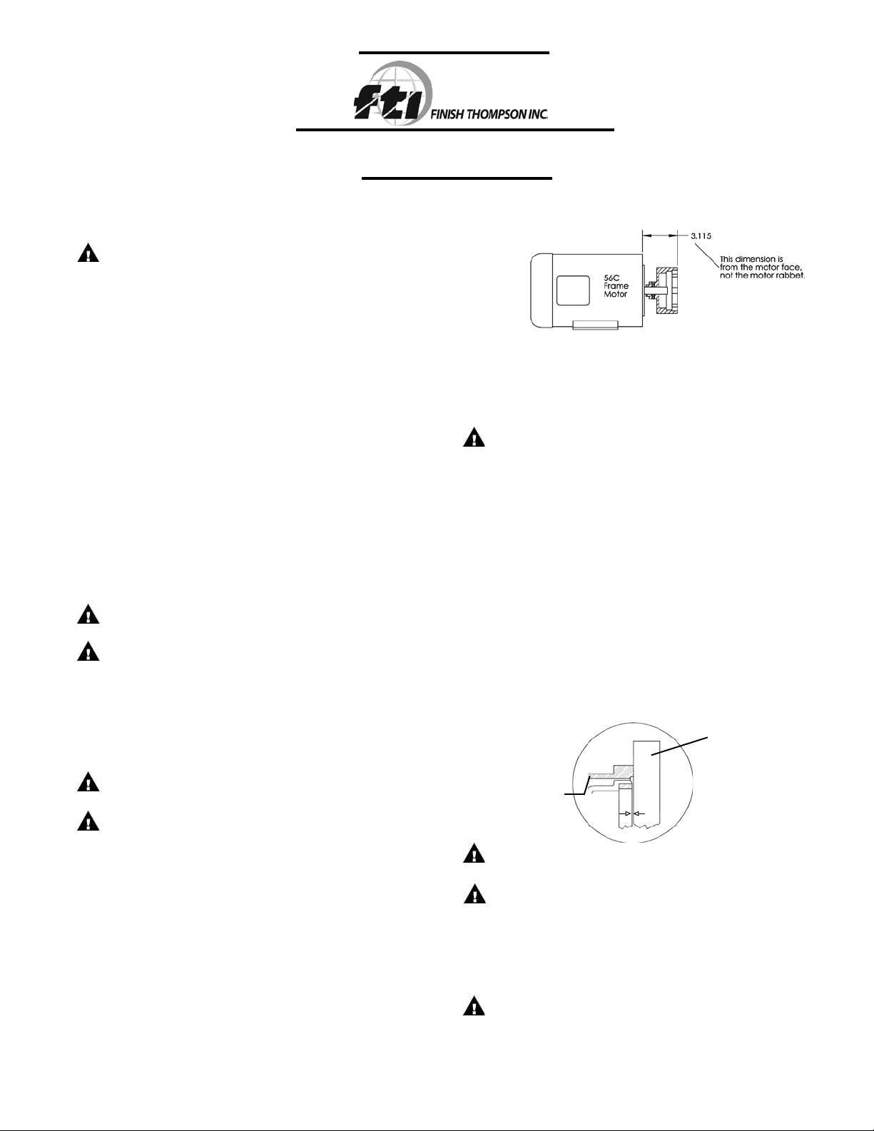
2. Slide drive magnet assembly (item 10) onto the motor shaft
until it is between 3.110” and 3.120” as measured from the
motor face to the top of the drive magnet assembly. See
Figure 1. Align cone point set screw (item 10B) with key slot
on the motor shaft and tighten both set screws with a 5/32”
Allen wrench to 140 in-lbs. (15.8 N-m).
CAUTION: Do not operate/test the motor with the drive
magnet assembly exposed.
WARNING: Magnets are strong. To avoid damage and pinch-
ing fingers, tightly grasp pump assembly keeping finger tips
away from the area where the motor adapter and motor meet.
3. Carefully slide the pump assembly over the drive magnet
assembly. Orient the discharge port to either the 12 or 9
o’clock position. Make sure rabbet (step) on motor is fully
seated into the motor adapter (item 11). Align bolt holes in
motor adapter and motor. Install (4) bolts and washers (items
14A,14B,14C) from hardware package.
4. Manually rotate pump assembly to ensure that the pump is
not binding or rubbing on the drive magnet assembly.
5. Install the pump into the system according to installation
instructions.
Figure 1
PUMPS WITHOUT MOTORS
(71/B14 & 80/B14 frame)
1. Remove pump, drive magnet assembly and hardware package
from box.
CAUTION: Keep away from metallic particles, tools and
electronics.
2. Remove screws and washers (items 12A, 12B & 12C) from
impeller housing (item 1) and remove wet end assembly from
motor adapter (item 11).
3. Install motor adapter onto motor (labels at top) and secure
with motor bolts and washers (items 14A, 14B, 14C) from
hardware package.
4. Slide the drive magnet (item 10) onto the motor shaft so that
the cone point setscrew (item 10B) is aligned with the motor
shaft keyway. Install the drive magnet so that it is recessed
1.016 mm (.040” +/- .005”) below the surface of the motor
adapter (see figure 2). Tighten both setscrews with a 5/32”
Allen wrench to 15.8 N-m (140 in-lbs.).
Figure 2
STRAIGHT
EDGE
DRIVE
T
MAGNE
ASSY.
CAUTION: Do not operate/test the motor with the drive
magnet assembly exposed.
CAUTION: Drive magnets MUST be free of metal chips.
Note: Prior to start-up, double check both drive magnet set
screws to assure that they are firmly tightened. Failure to do so
could result in internal damage. Rotate to assure clearance with
the motor adapter.
WARNING: Magnets are strong. To avoid damage and pinching fingers, tightly grasp pump assembly keeping finger tips away
from the area where the housing and motor adapter meet.
.040”
1
Page 2
5. Place wet end assembly (comprised of items 1-9) into the
motor adapter (item 11). Grasping the barrier at opposite
bolt tabs, carefully lower the wet end assembly into the motor adapter/drive assembly. Line up the tabs of the wet end
between the tabs on the motor adapter to avoid pinching
fingers. Once seated, rotate the wet end until bolt holes line
up.
6. Align mounting holes and install 6 mounting screws and
washers (items 12A, 12B & 12C) from hardware package.
Hand tighten screws using pattern shown in Figure 3.
7. Rotate motor fan to verify there is no internal binding or rubbing.
8. Install pump into the system according to installation instructions.
1
3
6
5
Figure 3
9. Install valves on suction and discharge lines (a minimum of
10 pipe diameters from the pump).
10. For units in a suction lift system, install appropriate piping in
the discharge to allow priming of the pump.
Note: This pump is not self-priming.
11. The suction valve should be completely open to avoid
restricting suction flow.
CAUTION:
To stop the pump if prime is lost, use one of the following:
(1) pressure switch on the discharge, (2) vacuum switch on
the suction, (3) a power monitor to monitor motor power.
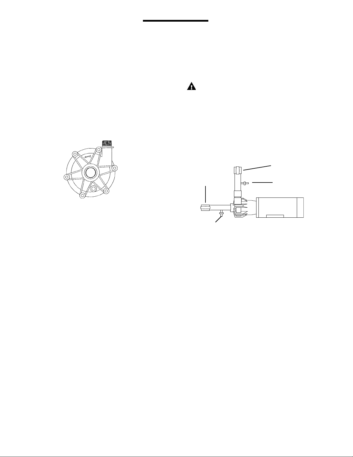
12. When pumping liquids that may solidify or crystallize, a flush
system should be added to the piping. See Figure 4. Install
water inlet and outlet valves as shown.
Note: This pump is provided with a provision for a customer
installed 1/4” NPT drain in the impeller housing. See Drain
Installation Section for details.
Discharge Valve
Suction
Valve
Water Inlet Valve
2
4
INSTALLATION
MOUNTING
Motor should be securely fastened.
PIPING
1. Support piping near the pump to eliminate any strain on the
pump casings.
2. Do not overtighten the piping on the discharge on initial
installation. Damage to the discharge can occur. An o-ring
can be used when there is wear and the plastic threads are
loose.
Note: BSP housings are shipped with an o-ring on the dis-
charge.
3. To minimize head loss from friction:
a. Increase pipe size by 1 diameter.
b. Use minimal number of pipe bends.
4. Keep bends and valves a minimum of 10 pipe diameters from
the suction and discharge.
5. Position pump as close to the liquid source as possible.
6. Maintain a flooded suction (liquid above pump prior to being
primed).
7. Ensure that the piping does not leak and suction is not prone
to clogging.
8. If flexible hose is preferred, use a reinforced hose rated for the
proper temperature and pressure. This helps avoid collapse
or kinks.
Water
Outlet
Valve
Figure 4
ELECTRICAL
Install motor according to NEC requirements and local electrical
codes. Motor should have an overload protection circuit.
IMPORTANT: To verify correct motor rotation:
1. Install pump into system.
2. Fully open suction and discharge valves.
3. Allow fluid to flow into the pump. Do not allow pump to run
dry (PTFE and ceramic bushings cannot be run dry without
damage to pump components).
4. Jog motor (allow it to run for one or two seconds) and observe
rotation of motor fan. Correct rotation is clockwise as viewed
from motor fan. Refer to directional arrow on pump.
Note: A pump running backwards will pump but at a greatly
reduced flow and pressure.
OPERATION
FLOODED SUCTION SYSTEM
1. Completely open suction and discharge valves
2. Start the pump and check liquid flow. If there is no flow, see
the Troubleshooting section.
3. Adjust the flow rate and pressure by regulating the discharge
valve. Do not attempt to adjust the flow with the suction valve.
2
Page 3
SUCTION LIFT SYSTEM
1. Prime the system by filling the priming chamber and/or suction line with a liquid. Allow time for trapped air to work its
way out.
2. If priming via filling the suction line, close the discharge valve
prior to returning the suction line to the tank.
FLUSH SYSTEMS
CAUTION: Some liquids react with water.
1. Completely close suction and discharge valves.
2. Connect water supply to water inlet valve.
3. Connect drain hose to water valve.
4. Open inlet and outlet valves. Flush system until pump is clean
(approximately 5 minutes).
MAINTENANCE
CAUTION:
Keep the drive magnet and impeller assemblies away from
metal chips or particles.
EXAMINATION
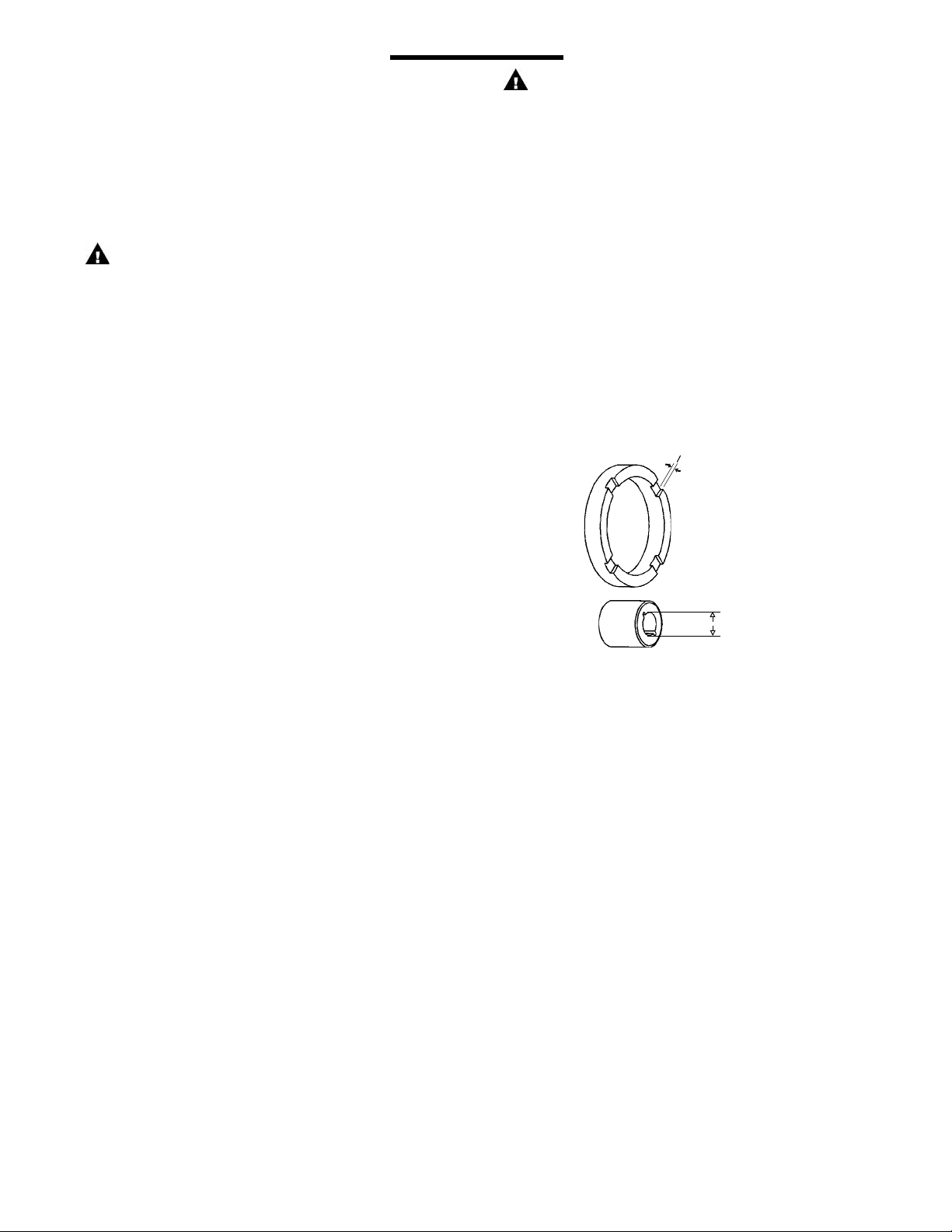
1. Check impeller bushings (item 8A) in both the impeller assembly (item 8) and the impeller drive shaft (item 3), check
both thrust rings (item 2A), both ceramic housing rings, and
both the barrier ceramic post and the first stage impeller
housing ceramic post for cracks, chips, scoring or excess
wear. See figure 5. Replace as required.
2. Check for loose magnets on drive magnet assembly or rubbed
areas on the impeller or barrier assemblies. Contact your
distributor or FTI Technical Service if a problem is found.
3. If you do not remove the drive magnet assembly, check the
set screws for tightness before reassembly.
DISASSEMBLY
1. Disconnect power. Remove electrical wiring and motor
mounting bolts.
2. Close suction and discharge valves. Disconnect piping.
3. Securely hold or clamp motor in place.
4. For 71/80 motor frame pump, skip to step 5. For 56C motor
frame pumps, remove the four motor adapter bolts (item 14A)
and pull the pump end away from the motor/drive magnet
assembly. Set pump end on motor adapter flange with suction facing up.
5. Remove the six screws (item 12A) from the impeller housing.
6. Using a thin bladed screwdriver, gently separate the first
stage housing (item 1) from the diffuser (item 5). Remove
the first stage impeller housing (item 1) being careful to pull
straight off so as not to damage the ceramic front spindle
support. Remove the housing o-ring (item 4). Holding down
on the outside of the diffuser assembly (item 5) with one
hand, gently pull the first stage impeller/impeller drive shaft
assembly (items 2 and 3) from the pump.
7. Remove the diffuser assembly (item 5) and the diffuser o-ring
(item 6) from the top of the second stage impeller housing
(item 7). Remove the second stage impeller housing, the
housing o-ring, the second stage impeller assembly (items
2 & 8), and the barrier (item 9) from the motor adapter (item
11).
8. If the drive magnet assembly (item 10) or the motor needs to
be replaced, do the following. On 56C frame motors, loosen
the two drive magnet set screws (items 10A and 10B) with a
5/32” hex wrench, and remove the drive magnet assembly.
On 71/80 frame motors, insert a 5/32” hex wrench into the
access hole on the top of the motor adapter (item 11) and
loosen the two set screws. Remove the drive magnet assembly from the motor shaft. Remove the motor adapter if
the motor is being replaced.
.020” min.
Figure 5
.415” max.
BUSHING REPLACEMENT
1. To remove the bushing in the second stage, insert 1/16” pin
punch into balance hole (inner circle of 4 holes) of impeller
drive. Gently tap the bushing out of the back of the impeller
drive. The punch may need to be moved to a different hole if
the bushing is difficult to remove.
2. To replace the bushing, clean the impeller bore. Insert the new
bushing into the back of the impeller drive by aligning the
bushing with the impeller bore. Press gently until the bushing
bottoms out (use a block of wood and mallet if necessary).
3. If the bushing in the impeller drive shaft is worn and needs
to be replaced, the complete impeller drive shaft with bushing (item 3) will need to be purchased. Grasp the impeller
assembly in one hand and pull the impeller drive shaft from it.
REASSEMBLY
If the drive magnet assembly (item 10) is to be replaced, install as
follows. On a 56C motor frame, slide the drive magnet assembly
(item 10) onto the motor shaft until it is between 3.110” and
3.120” as measured from the motor face to the top of the magnet
assembly. See figure 1. Align cone point set screw (item 10B)
with key slot on the motor shaft and tighten both set screws with
a 5/32” Allen wrench to 140 in-lbs. (15.8 N-m).
3
Page 4

For 71/B14 frame motors - Install the motor adapter (item
11) onto the motor face. Slide the drive magnet (item 10) onto
the motor shaft so that the cone point setscrew (item 10B) is
aligned with the motor shaft keyway. Install the drive magnet
so that it is recessed 1.016 mm (.040” +/- .005”) below the
surface of the motor adapter (see figure 2). Tighten both setscrews with a 5/32” Allen wrench to 15.8 N-m (140 in-lbs.).
For 56C motor frame pumps:
Place the barrier (item 9) onto the motor adapter (item 11). Align
the bolt hole tabs and press the barrier into the motor adapter
until it snaps in place. Place the second stage impeller assembly
(items 2 & 8) into the barrier (note orientation of the recessed
square in top of impeller assembly). Proceed to step 2.
For 71 and 80 motor frame pumps:
1. If possible, set motor on fan cover with drive magnet assembly
facing up. Place the second stage impeller assembly (comprised of items 2 and 8) into the barrier (item 9). Grasping
the barrier at opposite bolt tabs, carefully lower the barrier
assembly into the motor adapter (item 11). Line up the tabs
of the barrier between the tabs on the motor adapter to avoid
pinching fingers. Once seated, rotate the barrier until the bolt
holes line up.
2. Install the housing o-ring (item 4) on the barrier. Lubricate
the o-ring with a compatible lubricant to facilitate o-ring
installation.
3. Install the second stage impeller housing (item 7) onto the
barrier being careful not to dislodge the o-ring. Align the bolt
hole tabs and gently press together (bolt clearance alignment
is critical).
4. Install and lubricate the diffuser o-ring (item 6). Install the
diffuser assembly (item 5) making sure to keep bolt clearance
alignment straight and making sure not to dislodge the o-ring.
5. If the first stage impeller drive shaft (item 3 ) was replaced,
reassemble it to the impeller assembly by matching the three
tabs on the end of the drive shaft with the three recessed slots
in the impeller assembly (item 2) and press together.
6. Looking through the hole in the center of the diffuser assembly, note the orientation of the square recess in the top of
the impeller. Insert the square end of the drive shaft through
the hole and into the square recessed hole in the top of the
impeller. Press gently but firmly to seat the drive shaft.
7. Install and lubricate the housing o-ring. Coming straight
down, gently place the impeller housing (item 1) onto the
pump with the ceramic front spindle support sliding into the
bushing on top of the first stage impeller assembly (items 2
and 3). Orient the housing with the directional arrow on top,
the drain boss location on the bottom and with the mounting
holes aligned. Install the six mounting bolts, washers, and
lock washers (items 12A, 12B, and 12C). Make sure the
housing o-ring is not dislodged or pinched. Hand tighten the
mounting bolts to pull the pump together using the pattern
shown in figure 3.
8. After the housing is tightened down, insert a screwdriver
into the suction and push down on the front of the first stage
impeller assembly (Note: Do not press on gray thrust ring)
to completely set the impeller drive shaft (item 3) into the
second stage impeller (item 8). Push firmly on the three
areas separated by the spindle support arms in the suction.
Rotate the motor fan to verify nothing is rubbing.
9. 56C frame pumps. Carefully slide the pump assembly over
the drive magnet assembly. Orient the discharge port to either
the 12 or 9 o’clock position. Make sure the rabbet on the
motor is fully seated into the motor adapter (item 11). Align
the bolt holes in the motor adapter and the motor. Install 4
bolts and washers (items 14A,14B,14C) and tighten securely.
OPTIONAL DRAIN INSTALLATION SECTION
1. Remove the impeller housing from the pump assembly.
2. Clamp the impeller housing to a drill press table.
3. Using a 7/16” drill and the molded boss as a guide, drill
completely through the molded boss into the interior of the
impeller housing. De-burr the hole on the inside of the
impeller housing. See Figure 6.
CAUTION: Do not tap too deep or the impeller housing may
be damaged.
4. Using a 1/4” NPT tap, tap the hole in the molded boss to the
appropriate depth.
5. Install drain plug or valve, being careful not to overtighten.
Figure 6
Drain fitting molded boss.
Use as a guide for drilling
and tapping 1/4” NPT.
4
Page 5

Note: O-ring (item 15)is used
only with BSP threads.
5
Page 6

MSKC MULTI-STAGE SPARE PARTS
Item Description
1 Impeller Housing – first stage
Impeller with thrust ring
3.00” A101983-17 A101983-18
2
2A
3
4
5 Diffuser Assembly All A103242-1 A103242-4 1
6
7 Impeller Housing – second stage NPT/ BSP 107787-1 107787-2 1
8
8A
9 Barrier All 107788-1 107788-2 1
10 Drive Magnet Assembly
10A Set Screw – knurled point All J104219 1
10B Set Screw – cone point All J104220 1
11 Motor Adapter
12A C/S hex hd. ¼-20 x 5-1/2”LG. SS All J103873 6
12B ¼” lock washer All J100672 6
12C ¼” flat washer All J100113 6
13 Plug for motor adapter All J102878 2
14A
14B
14C
15
3.19” A101983-15 A101983-16
3.50” A101983-2 A101983-5
3.88” A101983-3 A101983-6
Thrust ring – PTFE
3.00”/3.19” J103893
3.50”/3.88” J101606
Impeller drive shaft with carbon bushing
Impeller drive shaft withPTFE bushing A103270-2 A103270-5
Impeller drive shaft with ceramic bushing A103270-3 A103270-6
Housing o-ring – FKM All J102389
Housing o-ring – EPDM J102585
Diffuser o-ring – FKM
Diffuser o-ring - EPDM J102446
Impeller Drive with carbon bushing
Impeller Drive with PTFE bushing A103269-2 A103269-5
Impeller Drive with ceramic bushing A103269-3 A103269-6
Impeller bushing – carbon
Impeller bushing – PTFE J102790
Impeller bushing – ceramic J103617
Motor Adapter Bolts
3/8-16 x 1” SS hex hd. cap screw 56C J100114
M6 x 16mm SS hex hd. cap screw 71 & 80 J102884
Motor Adapter Lock Washer
3/8” SS lock washer 56C J100115
¼” SS lock washer 71 & 80 J100672
Motor Adapter Flat Washers
3/8” SS flat washer 56C J100128
¼” SS flat washer 71 & 80 J100113
Discharge o-ring - FKM
Discharge o-ring - EPDM J102713
Frame
Size
NPT A103195-1 A103195-2
BSP A103195-3 A103195-4
All
All
All
All
56C A101990-15
71/B14 A101990-13
80/B14 A101990-14
56C A101991-3
71/B14 A101991-1
80/B14 A101991-2
BSP
Polypropylene PVDF
Part Number
A103270-1 A103270-4
J102447
A103269-1 A103269-4
J102387
J102391
Qty.
1
2*
1
1
2
1
1
1
1
1
4
4
4
1
*May be two different size impellers. See below. Check model number of serial number of label to determine impeller combina-
tions. Example: MSKCPCVN15C. The underline position indicates impeller combination.
1 = 3.88 + 3.88 2 = 3.5 + 3.88 3 = 3.5 + 3.5 4 = 3.19 + 3.5 5 = 3.0 + 3.5
6
Page 7

TROUBLESHOOTING
GENERAL NOTES:
1. Do not pump liquids containing metal fines.
2. Orient the discharge port to either 12 or 9 o’clock position.
3. If magnets decouple, stop the pump immediately. The rare
earth magnets used in this pump are more resistant to
demagnetization than ceramic magnets, but operating the
pump with the magnets decoupled will eventually weaken
the magnets.
4. Plastic pumps will expand and contract with temperature so
periodically check and hand-tighten screws. This pump is
designed to accept an o-ring on the discharge flange and inlet
chamfer as a backup to the NPT or BSP threads to ensure
leak-free operation after temperature cycling.
5. Fitting o-rings on discharge flange and inlet chamfer is possible.
NO DISCHARGE
1. Air leaks in suction piping.
2. Pump not primed.
3. Discharge head too high.
4. Suction lift too high or insufficient NPSHA. Suction lift should
be 2 feet above NPSHR.
5. Closed valve.
6. Viscosity or specific gravity too high (magnets uncoupled).
INSUFFICIENT DISCHARGE
1. Air leaks in suction piping.
2. Discharge head higher than anticipated.
3. Suction lift too high or insufficient NPSHA. Suction lift should
be 2 feet above NPSHR.
4. Clogged suction line, foot valve or crimp in hose.
5. Foot valve too small.
6. Foot valve or suction opening not submerged enough.
7. Incorrect pump rotation.
VIBRATION/NOISE
1. Excess bearing wear.
2. Drive magnet uncoupled.
3. Loose magnet.
4. Pump cavitating.
5. Motor or piping not properly secured.
6. Foreign object in impeller.
WARRANTY
Finish Thompson, Inc (manufacturer) warrants this pump product
to be free of defects in materials and workmanship for a period of
one year from date of purchase by original purchaser. If a warranted defect, which is determined by manufacturer’s inspection,
occurs within this period, it will be repaired or replaced at the
manufacturer’s option, provided (1) the product is submitted with
proof of purchase date and (2) transportation charges are prepaid
to the manufacturer. Liability under this warranty is expressly
limited to repairing or replacing the product of parts thereof and
is in lieu of any other warranties, either expressed or implied.
This warranty does apply only to normal wear of the product or
components. This warranty does not apply to products or parts
broken due to, in whole or in part, accident, overload, abuse,
chemical attack, tampering, or alteration. The warranty does not
apply to any other equipment used or purchased in combination
with this product. The manufacturer accepts no responsibility for
product damage or personal injuries sustained when the product is
modified in any way. If this warranty does not apply, the purchaser
shall bear all cost for labor, material and transportation.
Manufacturer shall not be liable for incidental or consequential
damages including, but not limited to, process down time, transportation costs, costs associated with replacement or substitution
products, labor costs, product installation or removal costs, or
loss of profit. In any and all events, manufacturer’s liability shall
not exceed the purchase price of the product and/or accessories.
INSUFFICIENT PRESSURE
1. Air or gasses in liquid.
2. Impeller diameter too small.
3. Discharge head higher than anticipated.
4. Incorrect pump rotation.
LOSS OF PRIME
1. Leaking suction or discharge line.
2. Suction lift too high or insufficient NPSHA. Should be 2 feet
above NPSHR.
3. Air or gasses in liquid.
4. Foreign matter in impeller.
5. Leaking valve.
EXCESSIVE POWER CONSUMPTION
1. System head lower than rating. Pumps too much liquid.
2. Specific gravity or viscosity of liquid pumped is too high or
higher than that defined in application.
3. Binding pump parts.
ORDERING SPARE PARTS
Spare parts can be ordered from your local distributor. Always
refer to the pump model number to avoid error.
OTHER FINISH THOMPSON PRODUCTS
Drum Transfer Pumps are available in sanitary construction, stainless steel, polypropylene and CPVC. Flows to 40 gpm, discharge
head to 80 feet and viscosities to 15,000 cP are available.
Portable Mixers for turbine mixing and blending handle up to
1,000 cP with gentle, non-vortexing circulation. Available in 316
stainless steel construction.
Centrifugal Pumps in polypropylene, PVDF, and stainless steel offer
a wide variety of sealing materials. Flows to 250 gpm, discharge
head to 130 feet, and temperature to 220oF (104oC) are available.
For more information, contact Finish Thompson Inc. or call our
Technical Service Hot Line, 1-800-888-3743, if you have any
questions regarding product operation or repair.
7
Page 8

Service 800-888-3743
P/N J104018, Rev. 11, 2/11/11
FT01-843K
 Loading...