

Page 1
f
y
b
n
f
d
by
r
b
p
g
t
y
g
a
d
N
y
N
g
t
Model LS-Jr.
Vacuum Attachment
Installation and Maintenance Instructions
INTRODUCTION
The LS-Jr. with vacuum attachment provides for safe in-house
reclamation of contaminated solvents with boiling points o
200° to 500°F (93° to 260°C). Most solvents conform easil
and safely to this thermal distillation process. However,
ecause most SOLVENTS ARE COMBUSTIBLE, EXTREME
CAUTION must be exercised when operating the unit. Whe
properly installed and operated, the LS-JrV provides long,
trouble-free service, reclaiming 3 to 4 gallons (11-15 liters) o
solvent in 6 to 8 hours. For your safe ty, reclamation is limite
design to this rate.
PRINCIPLES
The LS-JrV utilizes breakthrough technology to reclaim highe
oiling solvents. A unique v ertical solvent pump and JetVac are
immersed in a single reservoir and used to create a vacuum in
the distillation unit.
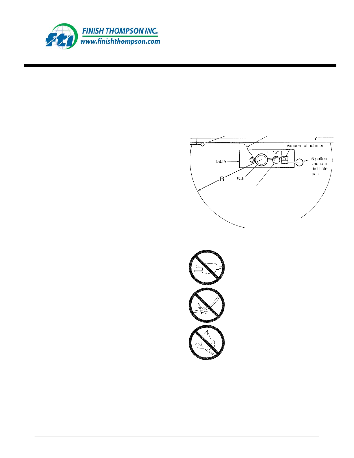
You must determine dimension R (see Figure 1). It illustrates
the larges t area where exp losive mixture s can be present. I n
well-ventilat ed area, R is of ten less than 10 ft. (3m). H owever,
R can also be more than 10 ft.
Explosionproof
conduit
Explosionproof
box
5-gallon
atmospheric
distillate pail
Explosionproof
wiring
Wall
Solvent in t he reservo ir tank is cir culated by th e solvent pu mp
through the high-velocity JetVac. This high-speed circulation
roduces a v acu um in the distill ation uni t. A co o ling c oil i n the
reservoir tank maintains solvent temperature. As additional
solvent is recovered and cooled, it is gravity fed from the
vacuum unit to a 5-
WARRANTY
When the LS-JrV is operated in strict accordance with these
instructions, it is guaranteed to recover h igher boiling solvents
See page 5 for detailed warranty information.
and is warranted 180 days from date of shipment agains
defects in materials and workmanship. All warranty claims
FOB Erie, Penns
allon distillate pail.
lvania.
INSTALLATION SITE
Install in a we ll-v entila ted area in a ccor dan ce with Artic les 5 00
and 501, Class I, Division 1, Group D of the National Electric
Code (explosion proof installation). Installation should be by a
qualified electrician and inspected by your insurance company.
The area surrounding the LS-JrV should be inspected carefully
to insure an explosionproof area. The LS-JrV must not be
installed in an area where open flame, sparks or electrical
are present.
arcin
Figure
Ignition of explosive mixtures can result from various items
causing "hot spots." Because of this, in the area defined by R,
the following are
Your qualified electrician can answer any questions you may
have for selecting the best LS-Jr. and vacuum attachmen
installation site and regard ing applicab le electrical codes.
1
ABSOLUTELY ESSENTIAL .
All electricals must be explosionproof har
conduit and explosion proof boxes.
o potential for sparks can be present (for
exam pie, non-explosion proof outlets and
electrical switches, coffeepots and other
appliances, static electricit
o flames can be present (for example,
torches, furnaces, ci
sources, etc.).
arettes, etc.).
WARNING:
The LS-Jr. is a boiling ve ssel, not a reactio n vessel . Chemi cal reactio ns with in the u nit mu st not be permit ted
to occur. The user must know the composition of the waste material to be processed. Most contaminated
solvents are recommended for the thermal distillation process. However, reactive materials must not be
processed in the LS-Jr. distilling unit. You must read and understand the caution printed on the lid of the unit
prior to operation, it reads
(example: lacquers with nitrocellulose) are processed."
:
"CAUTION: Dangerous health and safety problems will occur if reactive materials
Page 2
b
b
b
r
r
r
a
r
r
d
n
r
t
p
g
g
g
g
INSTALLATION
The LS-Jr. vacuum attachment should be installed on the distillate
discharge side of the LS-Jr. with 20 in. (51 cm) of clearance
ehind and 15 in. (38 cm) between the units. Enough clearance
must remain on floor level to the right of the vacuum unit for a 5gallon (19 liter) vacuum distillate receiving pail.
The LS-Jr. and vacuum attachment require 6 to 13 gallons (23-49
liters) of tap water per hour for cooling. Water enters and exits via
hoses on the rear of the units. Two valves are recommended
etween the water supply and the unit; one for on/off operation,
the other set to the desired flow rate. Water flow must be
confirmed prior to operation.
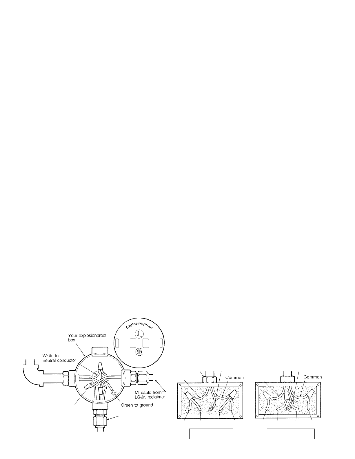
The LS-JrV requires an additional 115V, 1 phase, 60 Hz, 4 amps
with a separate ground or a 220V, 1 phase, 60 Hz, 2 amp
unit is available. All wiring must be connected to a suitable power
supply in accordance with the National Electric Code for Class I
installations (see Figure 2).
After installation, check the unit's ground. If the resistance
etween the unit and the transformer's earth ground exceeds
1 ohm, a separate ground must be installed from the unit to the
earth ground. The ground wire must be installed to insure safe
operation and to eliminate static spark hazard.
For simultaneous LS-Jr. and LS-Jr.V installation
Incoming water is supplied to the LS-Jr.V cooling wate
inlet (Item 14) on the rear of the vacuum unit. Connect
separate hose from the distillation unit cooling wate
discharge (Item 6) to a drain.
5. Install the cooling water connection hose between the
reclaimer and the vacuum unit. Slide one end of the hose
over the barbed fittings of the reclaimer's cooling wate
inlet (Item 5) and the other end to the vacuum unit's
cooling water discharge (Item 15).
6. Screw the vacuum distillate discharge hose (Item 10) into
the coupling (Item 24) provided on the side of the LS-JrV
reservoir tank. Place a receiving p ail next to the table an
cut the discharge hose to proper length.
7. Screw the flame-check assembly (Item 19) into the coupling provided on the back of the vacuum attachment reservoir tank.
8. Install a grounding cable (Item 23) between the distillatio
and vacuum units. To install, remove the bottom left screw
from the distillation unit hinge bracket, connect the
grounding cable and replace the screw. On the vacuum
unit, remove the screw between the cooling wate
discharge (Item 15) and the flame check (Item 19), connec
the grounding cable and replace the screw.
:
ASSEMBLY
Assembly of the vacuum attachment and connection to the LSJr. reclaimer requires a f ew simple steps. Proper assembly and
connection is necessary for operation. The following steps and
Figures 4 and 5 serve as as sembly guidelines.
1. Remove the discharge hose and fitting from the reclaime
(Item 8). Do not loosen or remove the connecting distillate pipe
from the unit.
2. Screw the quick-disconnect coupling onto the reclaimer
distillate pip e .
3. Screw the discharge hose and fitting (removed in Step 1)
onto the nipple assembly provided for future
atmosphe r ic distillation .
4.
For LS-Jr.V installation to an existing LS-Jr.:
Remove
the cooling water inlet hose (Item 5) from the back of the
reclaiming unit and connect to the vacuum unit cooling wate
discharge (Item 15).
Explosionproof cover-----
Your rigid
explosionproof
conduit
..
OPERATION
The LS-Jr.V requires minimal operator attention. The following
steps serve as operation guidelines.
For atmospheric distillation:
Atmospheric distillation allows reclamation of solvents with
boiling points to 300°F (149°C). To distill solvents atmos-
herically, connect the short distillate discharge hose to the
reclaimer unit with the quick-disconnect coupling. Then follow
Steps 1-11 in the LS-Jr. Installation and Operating Instructions
(F86-180-QP).
For vacuum distillation:
Vacuum d istillation allows r eclamation of solv ents with boiling
points with a minimum temperature of 200°F (93°C) and a
maximum temperature of 500°F (260°C). To distill solvents in
this temperature range under a vacuum:
1. Ground all filling and receiving containers, wiring static
ground clamps provided (Items 2 and 17).
Vacuum attachment
Incoming Power
(115V, 1 phase, 60 Hz,
with separate ground)
Entrance for
Ri
id Conduit
Ground
motor
wiring
Incoming Power
(220V, 1 phase, 60 Hz,
with separate ground)
Entrance for
Ri
id Conduit
Hot
Ground
Black to
fused conductor
Your explosionproof wiring
from LS-JrV (MI cable
Figure 2
orhard conduit)
#1 #3 #2 #4
For 115V Wirin
#1 #2 #3 #4
For 220V Wirin
Page 3

b
p
p
d
b
2. Install a STILGASKET for each batch processed, following
procedures in the LS-Jr. Installation and Operating
Instructions. If an optional STILBAG is used, carefully
insert bag, making sure no air pockets are present. Positon
the retainer ring prior to filling.
3. Pump or pour 3 to 4 gallons (11-19 liters) of contaminated
solvent from a grounded container into the reclaimer unit's
oiling vessel. Stamp ings on the inside wall of th e boilin g
chamber indicate fill lines. Some solvents may expand and
"foam over" during the distillation process. Ex
will dictate largest batch size to be processed.
4. Carefully position the reclaimer unit lid, lifting approximately 30° to avoid touching the STILGASKET. When in
osition, lower th e lid slowly, matching flange to flange.
Secure the spring release latch.
5. Insert the vac uum distillate hose (It em 25 ) in to th e qui ck
disconnect coupling (Item 8) on the reclaimer unit lid.
6. Remove the access lid (Item 18) on the vacuum unit and fill
tank with 3 gallons (11 liters) of clean solvent. Clean
solvent should be the same as solvent to be reclaimed.
Replace access lid on the vacuum unit tank.
7. Place a five-gallon pail on the floor beneath the vacuum
unit distillate discharge hose. Ground receiving vessel with
static ground clam p.
8. Turn on condenser water. (Operation experience will
determine proper adjustment of cooling water flow rate.
Generally it can be reduced until distillate temperature
increases.)
9. Push dist illation unit (Item 1) start/stop button. Red light
turns on.
10. Turn on vacuum unit motor (Item 20). After approximately
11/2 hours, solvent should be flowing through the
discharge hose into the receiving pail. When distillate flow
stops, the material has been reclaimed.
11. Push distillation unit start/ stop button. Red light turns off.
12. Remove vacuum-connection discharge hose from the
quick-disconnect coupling. Vacuum pressure should return
to 0 on vacuum gauge. (Note: Failure to disconnect
vacuum-connection hose will result in reclaimed solvent
being drawn into the distillation unit.)
13. Turn off vacuum motor.
14. After approxim ate l y half an hour, turn off cooli ng wat er .
15. Allow unit to cool overnight. Unsecure lid and slowly lift
30° vertically to break seal. Swing lid to back of unit.
16. Remove residue using STIL SCRAPER or similar plastic
utensil. (If optional STILBAG is used, remove retainer
ring and take out residue-filled STILBAG.)
erience
Solvent
Pressurizes recycled solvent from the reservoir tank to provide
a primary (motive) fluid to the JetVac pump.
pump
JetVac pump
Creates a vacu um in the distillatio n unit by combining a high velocity primary jet stream of solvent with a secondary stream
of leak- air a n d co n d ensate from t he d ist ill at io n unit. The JetVac
pump also elevates solvent vapors to near-atmospheric conditions and assists in the condensing process.
Check valve
Used for short intervals, the check valve prevents reclaimed
solvent from re-entering the reclaimer unit.
Y-strainer
Prevents plugging of the vacuum unit should a carry-over occur
by trapping large particles. After every 40-60 hours of operation, clean the screen within the V-strainer by removing an
rinsing
.
Cooling coils
Water circulation within the cooling coils cools solvent and
removes heat from compression, condensation and fluid
friction.
Flame-check
Prevents possible back-flash of flame into the reservoir tank.
Vacuum rel i e f
Allows adjustment to the vacuum, if nece ssary. Adjustment is
rarely necessary and factory settings will usually be
satisfactory. To adjust, loosen nuts to decrease vacuum, tighten
nuts to increase vacuum. During adjustment. vacuum pressure
is indicated on the vacuum gauge
valve
.
INSTRUMENTATION AND MAINTENANCE
Solvent reservoir tank
Contains clean solvent, cooling coils, a solvent pump and a
JetVac pump. An overflow pipe carries reclaimed distillate to a
receiving pail. Each co mponent in th e re se rvoir tank is u se d f or
either creating the required vacuum or condensing reclaimed
solvent.
After every 40-60 hours of operation, clean the inside of the
reservoir tank. Drain solvent from the tank and clean the tank
y wiping with a clean, dry cloth. Refill the reservoir tank with
3 gallons (11 liters) clean solvent.
c.
Page 4

18
17
4
1
13
9 16
22
3
20
4
Figure 4. Front View
5
6
21
15
11
3
7
2
Figure 5. Rear View
Item Description Item Description
1 Vacuum unit on/off switch 14 Vacuum unit cooling water inlet
2 Grounding cable for waste solvent container 15 Vacuum unit cooling water discharge (to No.5)
3 Grounding cable between units 16 Vacuum gauge
4 Distillate hose coupling 17 Grounding cable for vacuum distillate pail
5 Cooling water inlet to condenser (from No. 15) 18 Reservoir access door
6 Cooling water discharge to drain 19 Flame check
7 Grounding cable for atmospheric distillate pail 20 Receiving pail for atmospheric distillation
8 Quick-disconnect coupling 21 Receiving pail for vacuum distillation
9 Adjusting valve 22 Lighted start/stop button (LS-Jr.)
10 Vacuum distillate discharge hose
11 V-strainer
12 Explosionproof motor with on/off switch
13 Vacuum-connection hose
Page 5

CHEMICAL REACTION DISCLAIMER
The user must exercise primary responsibility in selecting the product’s materials of construction, which are compatible with the fluid(s) that come(s) in contact with the product. The user may consult Finish Thompson, Inc. (manufacturer) and a manufacturer’s representative/distributor agent to seek a recommendation of the product’ s material
of construction that offers the optimum available chemical compatibility .
However neither manufacturer nor agent shall be liable for product damage or failure, injuries, or any other damage
or loss arising out of a reaction, interaction or any chemical effect that occurs between the materials of the product’ s
construction and fluids that come into contact with the product’s internals.
WARRANTY
Finish Thompson, Inc (manufacturer) warrants this product to be free of defects in materials and workmanship for a
period of 3 years plus lifetime on the LS heater from date of purchase by original purchaser. If a warranted defect,
which is determined by manufacturer’s inspection, occurs within this period, it will be repaired or replaced at the
manufacturer’s option, provided (1) the product is submitted with proof of purchase date and (2) transportation
charges are prepaid to the manufacturer . Liability under this warranty is expressly limited to repairing or replacing
the product of parts thereof and is in lieu of any other warranties, either expressed or implied. This warranty does
apply only to normal wear of the product or components. This warranty does not apply to products or parts
broken due to, in whole or in part, accident, overload, abuse, chemical attack, tampering, or alteration. The manufacturer accepts no responsibility for product damage or personal injuries sustained when the product is modified in
any way . If this warranty does not apply, the purchaser shall bear all cost for labor , material and transportation.
Manufacturer shall not be liable for incidental or consequential damages including, but not limited to process down
time, transportation costs, costs associated with replacement or substitution products, labor costs, product installation or removal costs, or loss of profit. In any and all events, manufacturer’s liability shall not exceed the purchase
price of the product and/or accessories.
Service 1-800-888-3743
Part Number J100962, Rev 2
Literature ID Number FT03-878A
 Loading...