

Page 1
KC3, 4, & 5 SERIES
Non-Metallic Centrifugal Pumps
Installation and Maintenance Instructions
INSTINST
ALLAALLA
INST
INSTINST
WARNING:WARNING:
WARNING:
WARNING:WARNING:
earth magnets. When the pump is disassembled (not connected to a
motor) and the magnets are exposed, these magnets produce powerful magnetic fields. Individuals with cardiac pacemakers, implanted
defibrillators, other electronic medical devices, metallic prosthetic heart
valves, internal wound clips (from surgery), metallic prosthetic devices
or sickle cell anemia must not handle or be in the proximity of the
magnets contained inside the pump. Consult a health care provider for
specific recommendations before working with this pump.
TIONTION
ALLA
TION
ALLAALLA
TIONTION
Magnetic field hazard. Magnetic field hazard.
Magnetic field hazard. This pump contains powerful rare
Magnetic field hazard. Magnetic field hazard.
MOUNTING
Motor should be securely fastened.
PIPING
1. Support piping near the pump to eliminate any strain on the pump
casings.
2. To minimize head loss from friction:
(a) Increase pipe size by 1 diameter.
(b) Use minimal number of pipe bends.
3. Position pump as close to the liquid source as possible.
4. Maintain a flooded suction (liquid above the pump prior to being
primed).
5. Ensure that the piping does not leak and suction is not prone to
clogging.
6. If flexible hose is preferred, use a reinforced, chemically compatible hose rated for the proper temperature and pressure. This
helps avoid collapse or kinks.
7. Install valves on suction and discharge lines (a minimum of 10
pipe diameters from the pump).
8. For units in a suction lift system, install appropriate piping in the
discharge to allow priming of the pump.
9. The suction valve should be completely open to avoid restricting the suction flow.
CAUTION:CAUTION:
CAUTION: To stop the pump if prime is lost, use one of the follow-
CAUTION:CAUTION:
ing: (1) pressure switch on the discharge, (2) vacuum switch on
the suction, (3) a power monitor to monitor pump motor power.
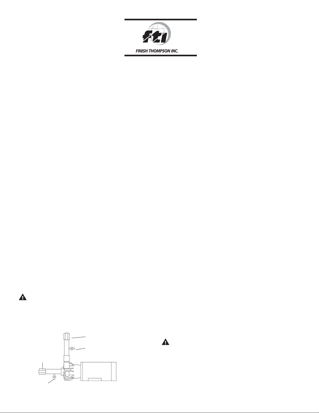
10. When pumping liquids that may solidify or crystallize, a flush system should be added to the piping. See Figure 1. Install water inlet
and outlet valves as shown.
Discharge Valve
Water Inlet Valve
Suction
Valve
Figure 1
Sealless
ELECTRICAL
1. Install the motor according to NEC requirements and local
electrical codes. Motor should have an overload protection
circuit.
2. Wire the motor for counter clockwise rotation when facing the
fan end of the motor.
3. To verify the correct rotation of the motor:
a. Install the pump into the system.
b. Fully open the suction and the discharge valves.
c. Allow fluid to flow into the pump. Do not allow the pump to
run dry. (Due to the unique magnetic design of this pump, it
can’t be run dry without damage to the internal pump
components).
d. Jog the motor (allow it to run for only one to two seconds)
and observe the rotation of the motor fan. Refer to the
directional arrow on the pump if needed.
NOTENOTE
::
NOTE
: A pump running backwards will pump but at a greatly
NOTENOTE
::
reduced flow and pressure.
OPERAOPERA
OPERA
OPERAOPERA
TIONTION
TION
TIONTION
FLOODED SUCTION SYSTEM
1. Completely open suction and close discharge valve.
2. Start the pump. Adjust the flow rate and pressure by regulating the
discharge valve. Do not attempt to adjust the flow with the suction
valve.
3. Check liquid flow. If there is no flow, see the Troubleshooting
section.
SUCTION LIFT SYSTEM
1. Prime the system by filling the priming chamber and/or suction
line with liquid.
2. Allow time for trapped air to work its way out.
3. Start the pump. Adjust the flow rate and pressure by regulating the
discharge valve. Do not attempt to adjust the flow with the suction valve.
4. Check liquid flow. If there is no flow, see the Troubleshooting
section.
FLUSH SYSTEMS
CAUTIONCAUTION
CAUTION
CAUTIONCAUTION
1. Completely close suction and discharge valves.
2. Connect water (or flush solution) supply to water inlet valve.
3. Connect drain hose to water valve.
4. Open inlet and outlet valves. Flush system until pump is clean
(approximately 5 minutes).
::
: Some liquids react with water.
::
Water Outlet
Valve
1
Page 2
MAINTENANCEMAINTENANCE
MAINTENANCE
MAINTENANCEMAINTENANCE
DISASSEMBLY
1. Disconnect power. Remove electrical wiring and motor mounting bolts.
2. Close suction and discharge valves. Disconnect piping.
3. Remove nuts, lock washers and flat washers from motor studs.
4. Pull the pump assembly (items 1, 2 ,2A, 3, 5, 6) off the motor.
5. Remove the screws (item 6) holding the pump assembly
together and separate the impeller housing (item 1) from the
barrier assembly (item 3).
6. Remove the drive magnet assembly (item 4), if necessary, to
change the motor. Use a 1/8” Allen wrench to loosen the two set
screws (item 4A). Remove the drive magnet assembly from the
motor shaft.
CAUTIONCAUTION
CAUTION
CAUTIONCAUTION
from metal chips or particles.
::
:
Keep the drive magnet and impeller assemblies away
::
EXAMINATION
1. Check the impeller drive bushing, thrust ring, ceramic thrust ring
and ceramic shaft for cracks, chips, scoring or excess wear. See
Figure 2. Replace as required.
.293 min.- PVDF
.313 min. - PP
.280 max.
Figure 2
2. Check for loose magnets on the drive magnet assembly or
rubbed areas on the impeller or barrier assemblies.
3. Check the o-ring for damage, cracking or swelling. Replace as
required.
4. If you did not remove the drive magnet assembly, check the set
screws for tightness before reassembly.
REASSEMBLY
1. Place the impeller assembly (item 2, 2A) over the ceramic shaft in
the barrier.
2. Install the o-ring (item 5) on the impeller housing (item 1).
Lubricate the o-ring with a compatible lubricant to facilitate oring installation.
3. Place the impeller housing (item 1) onto the barrier (item 3)
being careful not to dislodge the o-ring.
4. Align the holes in the impeller housing and barrier and install the
8 mounting screws (item 6). Using a screwdriver, hand-tighten
screws being careful not to overtighten.
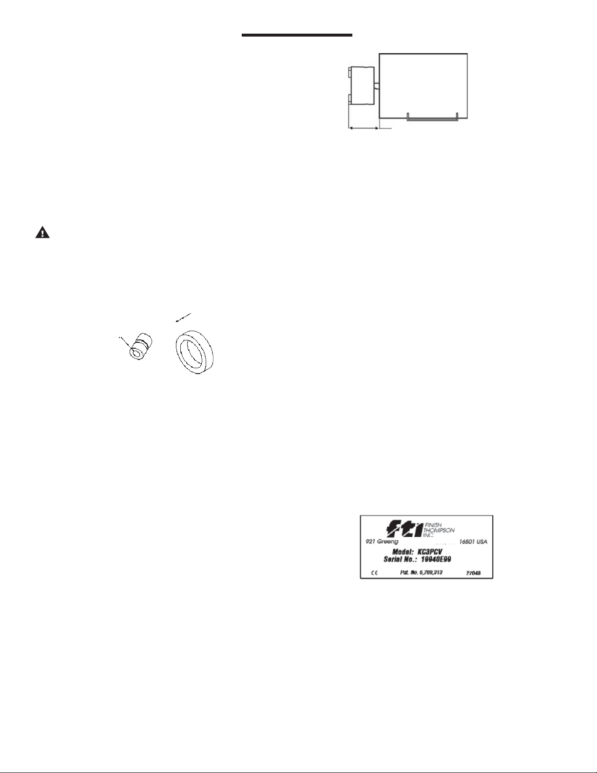
5. If the drive magnet (item 4) was removed, reinstall by sliding
drive magnet assembly onto the motor shaft until a distance of
1.69”+/- .015” is measured from the face of the motor to the top
of the drive magnet. See Figure 3. Align one set screw (item 4A)
with flat on motor shaft and tighten both set screws with 1/8”
Allen wrench to 70 in-lbs. (7.9 N-m).
1.69” +/- .015” KC3, 4 and 5
Figure 3
6. Carefully slide the pump assembly over the drive magnet
assembly. Orient the discharge to either 12 or 3 o’clock
position. Align bolts from the motor with the holes in the barrier.
Install flat washer, lock washer and nuts. Securely tighten nuts.
7. Manually rotate pump assembly to ensure that the pump is not
binding or rubbing on the drive magnet assembly.
GENERAL NOTESGENERAL NOTES
GENERAL NOTES
GENERAL NOTESGENERAL NOTES
1. Do not allow the KC3, 4, or 5 to run dry.
2. Do not pump liquids containing metal fines.
3. Orient the discharge port to either 12 or 3 o’clock position.
4. The setting of the drive magnet dimension is critical. Failure to
properly set the proper dimension may result in decoupling or
damage to pump components.
5. Make sure the pump is filled with liquid before starting the
pump.
6. If magnets decouple, stop the pump immediately. The rare earth
magnets used in this pump are more resistant to demagnetization than ceramic, but operating the pump with the magnets
decoupled will eventually weaken the magnets.
7. Plastic pumps will expand and contract with temperature so
periodically check and hand tighten the screws.
8. An information sticker is attached to the barrier section. The
first line is the model number, the second line is the serial
number. See Figure 4.
Figure 4
2
Page 3
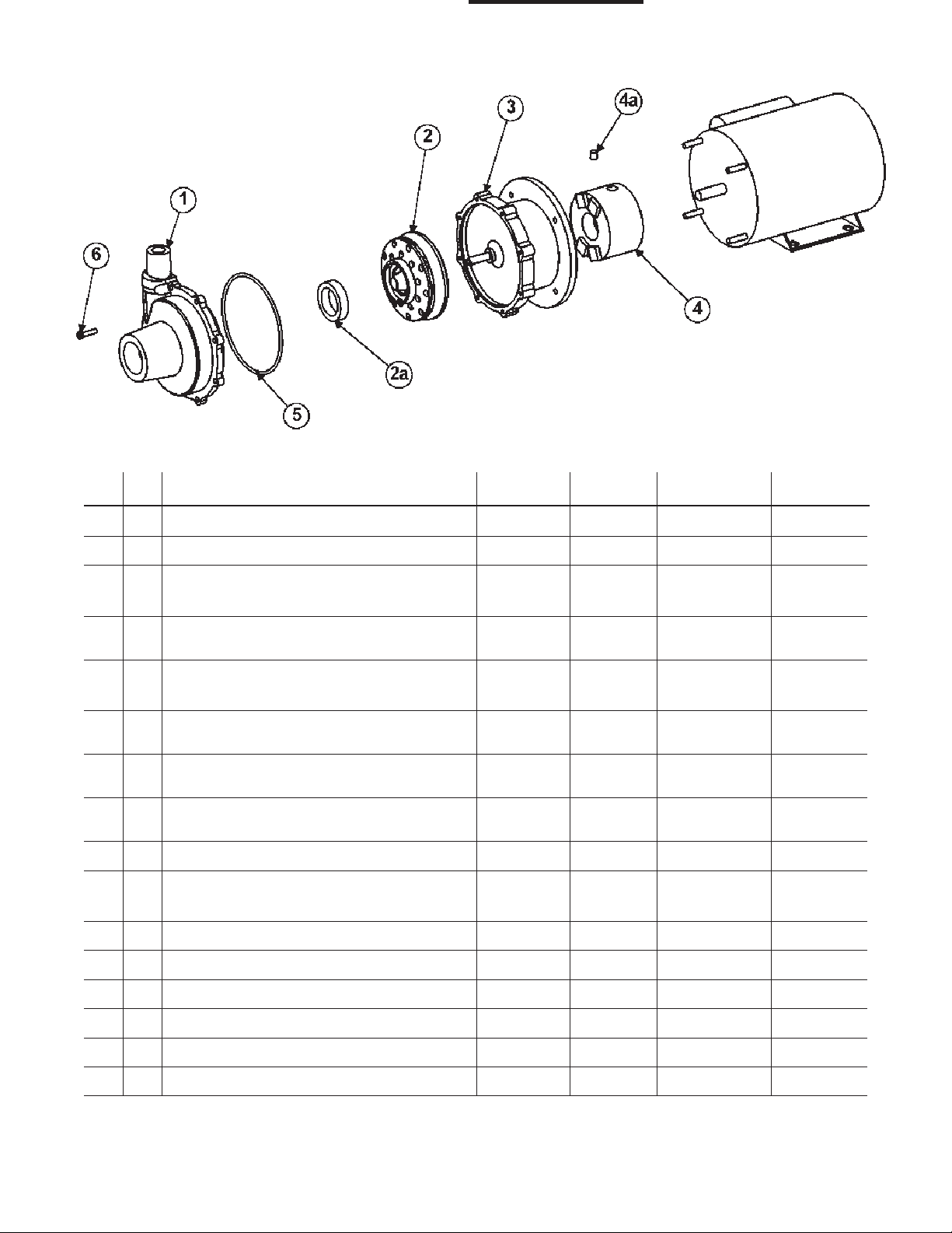
Figure 5
ItemItem
Item
ItemItem
QtyQty
Qty
QtyQty
DescriptionDescription
Description
DescriptionDescription
PumpPump
Pump
PumpPump
ThreadThread
Thread
ThreadThread
PP Part No.PP Part No.
PP Part No.
PP Part No.PP Part No.
PVDF Part No.PVDF Part No.
PVDF Part No.
PVDF Part No.PVDF Part No.
1 1 Impeller Housing with Thrust Ring KC 3, 4, 5 NPT A102865-1 A102865-3
1 1 Impeller Housing with Thrust Ring KC3, 4, 5 BSP A102865-2 A102865-4
2 1 Impeller Assemlby with Thrust Ring
and Carbon Bushing KC3 N/A A102861-1 A102861-3
2 1 Impeller Assembly with Thrust Ring
and PTFE Bushing KC3 N/A A102861-2 A102861-4
2 1 Impeller Assembly with Thrust Ring
and Carbon Bushing KC4 N/A A102861-5 A102861-7
2 1 Impeller Assembly with Thrust Ring
and PTFE Bushing KC4 N/A A102861-6 A102861-8
2 1 Impeller Assembly with Thrust Ring
and Carbon Bushing KC5 N/A A102861-9 A102861-11
2 1 Impeller Assembly with Thrust Ring
and PTFE Bushing KC5 N/A A102861-10 A102861-12
2A 1 Impeller Thrust Ring KC3, 4, 5 N/A M102141 M102141-1
3 1 Barrier Assembly with Spindle
and Thrust Washer KC3, 4, 5 N/A A102858-1 A102858-2
4 1 Drive Magnet Assembly KC3 N/A A102869-1 A102869-1
4 1 Drive Magnet Assembly KC4, 5 N/A A102869-2 A102869-2
4A 2 Set Screw KC3, 4, 5 N/A J100220 J100220
5 1 Housing O-ring -EPDM KC3, 4, 5 N/A J103571 J103571
5 1 Housing O-ring -Viton KC3, 4, 5 N/A J103572 J103572
6 8 Housing Screws KC3, 4, 5 N/A J101020 J101020
3
Page 4

TROUBLESHOOTINGTROUBLESHOOTING
TROUBLESHOOTING
TROUBLESHOOTINGTROUBLESHOOTING
NO OR INSUFFICIENT DISCHARGE
1. Air leaks in suction piping.
2. Pump not primed.
3. Discharge head higher than anticipated.
4. Closed valve.
5. Viscosity or specific gravity too high (magnets uncoupled).
6. Suction lift too high or insufficient NPSH.
7. Check for clogged suction line.
8. Motor rotation incorrect (counterclockwise as viewed from the
motor fan end).
INSUFFICIENT PRESSURE
1. Air or gas in liquid.
2. Impeller diameter too small.
3. Discharge head higher than anticipated.
4. Motor speed insufficient (too low) or motor rotation incorrect
(clockwise as viewed through the suction port).
LOSS OF PRIME
1. Leaking suction line.
2. Foot valve or suction opening not submerged enough.
3. Foot valve too small or leaking.
4. Air or gas in liquid.
5. Foreign matter in impeller.
6. Leaking valve. Suction lift too high or insufficient NPSH.
EXCESSIVE POWER CONSUMPTION
1. Head lower than rating. Excessive flow.
2. Specific gravity or viscosity too high.
VIBRATION/NOISE
1. Loose magnet.
2. Drive magnet rubbing.
3. Pump cavitating from improper suction or feed.
4. Motor or piping not properly secured.
5. Foreign object in impeller.
part, accident, overload, abuse, chemical attack, tampering, or
alteration. The warranty does not apply to any other equipment
used or purchased in combination with this product. The
manufacturer accepts no responsibility for product damage or
personal injuries sustained when the product is modified in any way.
If this warranty does not apply, the purchaser shall bear all cost for
labor, material and transportation.
Manufacturer shall not be liable for incidental or consequential
damages including, but not limited to process down time,
transportation costs, costs associated with replacement or
substitution products, labor costs, product installation or removal
costs, or loss of profit. In any and all events, manufacturer’s liability
shall not exceed the purchase price of the product and/or accessories.
CHEMICAL REACTION DISCLAIMERCHEMICAL REACTION DISCLAIMER
CHEMICAL REACTION DISCLAIMER
CHEMICAL REACTION DISCLAIMERCHEMICAL REACTION DISCLAIMER
The user must exercise primary responsibility in selecting the
product’s materials of construction, which are compatible with the
fluid(s) that come(s) in contact with the product. The user may
consult Finish Thompson, Inc. (manufacturer) and a manufacturer’s
representative/distributor agent to seek a recommendation of the
product’s material of construction that offers the optimum available
chemical compatibility.
However neither manufacturer nor agent shall be liable for product
damage or failure, injuries, or any other damage or loss arising out of
a reaction, interaction or any chemical effect that occurs between
the materials of the product’s construction and fluids that come into
contact with the product’s internals.
ORDERING SPORDERING SP
ORDERING SP
ORDERING SPORDERING SP
Spare parts can be ordered from your local distributor. Always refer
to the pump model number to avoid error.
OTHER FINISH THOMPSON PRODUCTSOTHER FINISH THOMPSON PRODUCTS
OTHER FINISH THOMPSON PRODUCTS
OTHER FINISH THOMPSON PRODUCTSOTHER FINISH THOMPSON PRODUCTS
ARE PARE P
ARE P
ARE PARE P
ARAR
AR
ARAR
TSTS
TS
TSTS
WARRANTYWARRANTY
WARRANTY
WARRANTYWARRANTY
Finish Thompson, Inc (manufacturer) warrants this pump product
to be free of defects in materials and workmanship for a period of
one year from date of purchase by original purchaser. If a warranted
defect, which is determined by manufacturer’s inspection, occurs
within this period, it will be repaired or replaced at the manufacturer’s
option, provided (1) the product is submitted with proof of purchase
date and (2) transportation charges are prepaid to the manufacturer.
Liability under this warranty is expressly limited to repairing or
replacing the product or parts thereof and is in lieu of any other
warranties, either expressed or implied. This warranty does apply
only to normal wear of the product or components. This warranty
does not apply to products or parts broken due to, in whole or in
Drum TDrum T
Drum T
Drum TDrum T
less steel, polypropylene, PVDF and CPVC. Flows to 40 gpm, discharge heads to 300 feet and viscosities to 100,000 cP are
available.
Portable MixersPortable Mixers
Portable Mixers for turbine mixing and blending handle viscosities
Portable MixersPortable Mixers
to 1,000 cP with gentle, non-vortexing circulation. Available in 316
stainless steel construction.
Centrifugal PumpsCentrifugal Pumps
Centrifugal Pumps in polypropylene, PVDF, 316 stainless steel, and
Centrifugal PumpsCentrifugal Pumps
ETFE lined ductile iron come with a wide variety of sealing materials.
Flows to 330 gpm, discharge heads to 325 feet, and temperatures
to 220oF (104oC) are available.
Call our TCall our T
Call our T
Call our TCall our T
any questions regarding product operation or repairany questions regarding product operation or repair
any questions regarding product operation or repair
any questions regarding product operation or repairany questions regarding product operation or repair
4
ransfer Pumpsransfer Pumps
ransfer Pumps are available in sanitary construction, stain-
ransfer Pumpsransfer Pumps
echnical Serechnical Ser
echnical Ser
echnical Serechnical Ser
FT99-759I, 5-16-07
Service 800-888-3743
P/N J103803, Rev. 8
vice Hot Line, 1-800-888-3743, if you havevice Hot Line, 1-800-888-3743, if you have
vice Hot Line, 1-800-888-3743, if you have
vice Hot Line, 1-800-888-3743, if you havevice Hot Line, 1-800-888-3743, if you have
..
.
..
 Loading...