

Page 1
KC22/32 SERIES Sealless
Non-Metallic Centrifugal Pumps
Installation and
Maintenance Instructions
ASSEMBLY
Unpack pump from carton and check for shipping damage.
WARNING: Magnetic field hazard. This pump contains powerful rare
earth magnets. When the pump is disassembled (not connected to a motor)
and the magnets are exposed, these magnets produce powerful magnetic fields.
Individuals with cardiac pacemakers, implanted defibrillators, other electronic
medical devices, metallic prosthetic heart valves, internal wound clips (from
surgery), metallic prosthetic device or sickle cell anemia must not handle or be
in the proximity of the magnets contained inside the pump. Consult a health
care provider for specific recommendations before working with this pump.
ATEX COMPLIANT PUMPS
All assembly, installation, and maintenance instructions are the same as
standard pumps with the exceptions noted on page 3 under "Safety Precautions
for ATEX pumps."
PUMPS WITH MOTORS
Remove shipping plugs and insert from suction and discharge and proceed to
installation instructions.
PUMPS WITHOUT MOTORS
1. Remove wet end assembly from box.
CAUTION: Strong magnets present. Keep metal objects and
metallic chips/particles away from pump components.
2. Remove hardware package from box.
3. Install motor adapter (item 6) onto motor with labels at top
using items 10 and 11.
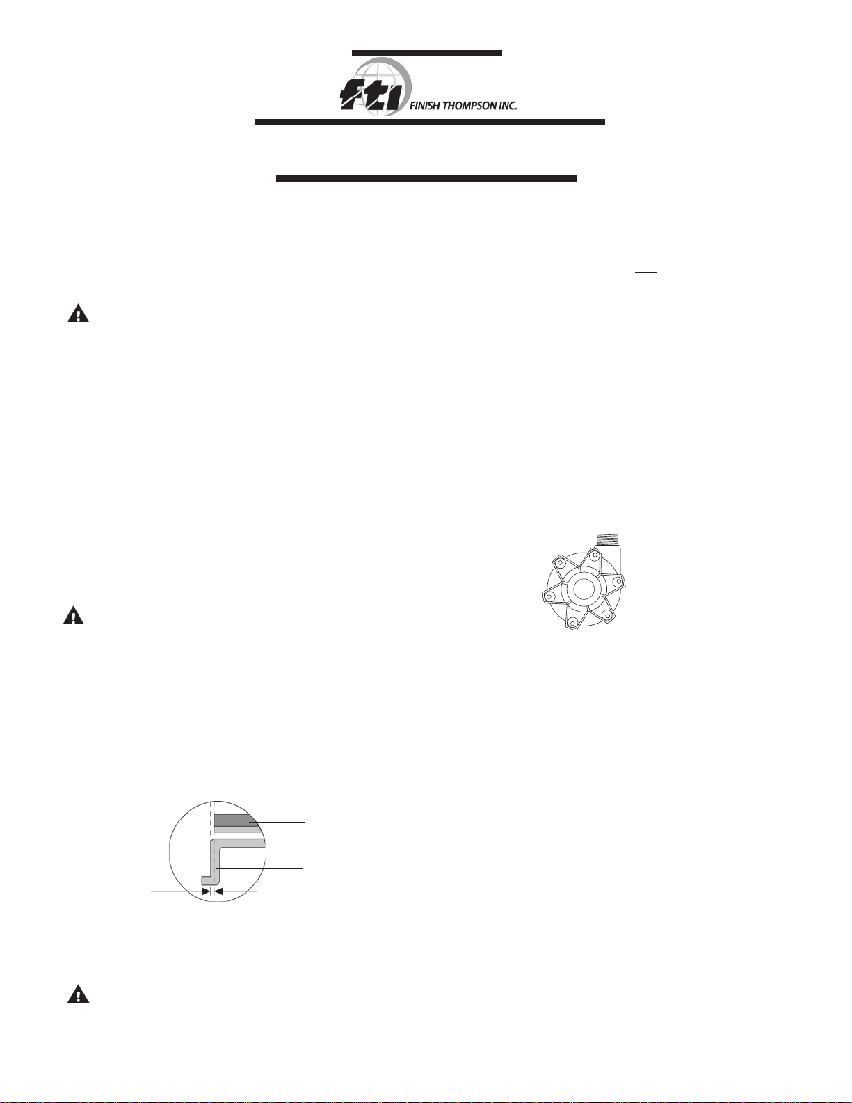
4. Remove drive mag assembly (item 5) from box and slide
assembly onto motor shaft making sure shaft key (item 12)
is in place. Installation dimension is .060 +/‑.010 inches as
shown in Figure 1. Tighten 2 set screws (item 5A) to 228
in‑lbs. (25.8 N‑m).
Item 5
Drive Magnet
Assembly
Item 6
Motor Adapter
.060 +/‑ .010
Figure 1
IMPORTANT: Verify the tightness of the set screws in the
drive magnet assembly prior to operation.
WARNING: Components can slam together from strong
magnets. Keep fingers away from area between housing
and motor adapter.
5. Gripping the discharge and the side of the impeller hous‑
ing (note above warning), carefully install the wet end into
the motor adapter. Note that the two housing studs (item
15) should be located at 3 and 9 o'clock (for 12 o'clock
discharge location) and will go through the motor adapter.
6. Install the 5/16 x 3/4 SS hex bolts (item 7), the 5/16 flat
washers (item 9), and the 5/16 hex nuts (item 8) and
tighten to 70 in‑lbs. of torque using the pattern shown in
figure 2.
7. Remove the two‑piece shipping plug from the suction.
8. Reach into the suction and spin the impeller to check if it
spins freely. If it does not, disassemble and recheck the
drive hub installation instructions in step 4.
9. Install pump into the system according to the following
installation instructions.
3
1
Figure 2
6
4
5
2
INSTALLATION
MOUNTING
Motor or base plate should be securely fastened.
PIPlNG
1. Support piping near the pump to minimize strain on pump
casing.
2. To minimize head loss due to friction:
a. Increase pipe size 1 diameter
b. Use minimal number of bends
3. Keep pipe bends a minimum of 10 pipe diameters from
suction and discharge. For example, if using 2" pipe, first
bend should be at least 20" from suction discharge.
4. Position pump as close to liquid source as possible.
5. Maintain a flooded suction.
6. Ensure that piping is leak proof.
7. Install valves on suction and discharge lines (minimum of
10 pipe diameters from pump).
8. For units in suction lift system, install appropriate piping in
discharge to allow priming of pump.
Page 2
9. The suction valve should be fully open to avoid restricting
suction flow.
IMPORTANT: To protect the pump if prime is lost, use one
of the following: (1 ) pressure switch on the discharge;
(2) vacuum switch on the suction; (3) a power monitor to
monitor motor current.
10. When pumping liquids which may solidify or crystallize, a
flush system should be added to the piping. See Figure 3.
Install water inlet and outlet valves as shown.
Discharge
Valve
Suction
Valve
Water Outlet
Valve
Figure 3
Water Inlet
Valve
ELECTRICAL
Install motor according to NEC requirements and local electrical
codes.
IMPORTANT: To verify correct motor rotation: (1) Install pump into system.
(2) Fully open suction and discharge valves. (3) Allow fluid to flow into the
pump. Do not allow pump to run dry (PTFE and ceramic bushings cannot be
run dry without damage to pump components). (4) Jog motor (allow it to run
for one or two seconds) and observe rotation of motor fan. Correct rotation is
clockwise as viewed from motor fan. Refer to directional arrow on pump.
OPERATION
START UP
1. This pump must be filled from a flooded suction tank
(gravity) or primed with liquid from an outside source. The
KC22/32 are not self‑priming.
2. Open the inlet (suction) and discharge valves completely
and allow the pump to fill with liquid.
3. Close the discharge valve.
4. Turn the pump on. Slowly open the discharge valve. Adjust
the flow rate and pressure by regulating the discharge
valve. Do not attempt to adjust the flow with the suction
valve.
5. Use of a power monitor is strongly recommended for
pumps with ceramic, PTFE or silicon carbide bushings.
The power monitor will stop the pump and help prevent
damage should the pump run dry. ATEX certified pumps
MUST use a power monitor.
SHUT DOWN
Use the following procedure to shutdown the pump.
1. Slowly close the discharge valve.
2. Turn off the motor.
3. Close the suction valve.
3. Connect drain hose to water outlet valve.
4. Open inlet and outlet valves, and flush system until pump
is clean (approximately 5 minutes).
MAINTENANCE
DISASSEMBLY
1. Disconnect power. Remove electrical wiring and mounting
bolts to floor or base plate.
2. Close suction and discharge valves, and disconnect piping.
3. Remove bolts, nuts and washers (items 7, 8 and 9). Leave
the 2 housing studs (item 15) in place until the wet end is
removed.
4. Securely clamp or hold motor in place. Remove wet end
assembly by inserting both thumbs into pump suction and
pulling assembly straight out with a quick motion.
WARNING: Components can slam together from strong
magnets. Keep fingers away from area between housing
and motor adapter.
5. Disassemble wet end by removing 2 housing studs and
nuts (items 16) which attach barrier (item 4) to impeller
housing (item 1). Remove and discard o‑ring (item 13).
6. Remove drive magnet assembly by inserting a 3/16" hex
wrench into access hole in side of motor adapter and
loosening 2 set screws (item 5A). Grasp inside of magnet
assembly and pull off of motor shaft.
CAUTION: Strong magnets present. Keep metal objects and
metallic chips/particles away from pump components.
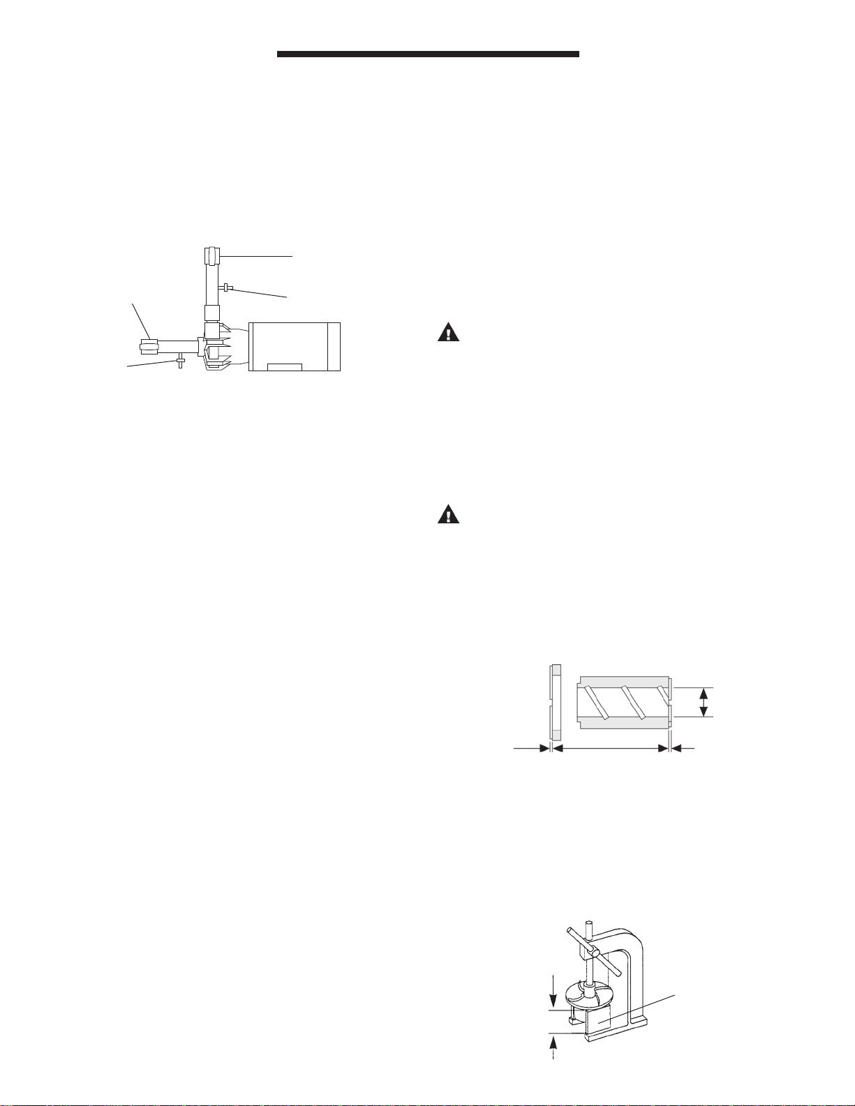
EXAMINATION
1. Check impeller drive bushing (item 3A) and impeller thrust
washer (item 2A). If cracked, chipped or scored, then
replace. Replace if minimum groove height is less than the
minimum height recommended. See Figure 4.
2. Check for loose magnets.
.780 MAX.
.020 MIN.
Groove Height
IMPELLER DISASSEMBLY
1. To separate impeller body (item 2) from the impeller drive
(item 3), support the body in an arbor press using two 5"
minimum spacer blocks.
2. Insert a 1‑1/2" diameter plastic or wooden shaft into the
impeller eye, and push the drive out of the body. See
Figure 5.
5” MIN.
Diameter
Figure 4
FLUSH SYSTEM
1. Fully close suction and discharge valves.
2. Connect water supply to water inlet valve.
Support
Figure 5
2
Page 3

Note: On closed impellers, use two screwdrivers in slots provided to pry
apart impeller and impeller drive.
BUSHING AND THRUST RING REPLACEMENT
1. To remove the bushing, place the impeller assembly (items
2 and 3) in an arbor press. Insert a 1" diameter plastic or
wooden shaft through the impeller and press bushing out.
Refer to Figure 6.
Figure 6
SAFETY PRECAUTIONS FOR ATEX PUMPS
CAUTION: Proper o‑ring material must be chosen for the fluid being
pumped. Improper material selection could lead to swelling and be a possible
source of leaks. This is the responsibility of the end user.
WARNING: The pump must be checked for leaks on a regular basis. If
leaks are noticed, the pump must be repaired or replaced immediately.
WARNING: The pump must be cleaned on a regular basis to avoid dust
buildup greater than 5 mm.
WARNING: ATEX pumps must use a power monitor, flow switch, pressure
switch or similar device to help protect against dry running, closed discharge
valve and decoupling. Any of these conditions could lead to a rise in surface
temperature of the pump.
TEMPERATURE CLASSIFICATION
2. To replace bushing, place the impeller assembly (items
2 and 3) on a flat surface with the thrust ring face down
(item 2A). Insert the bushing (item 3A), slotted face out,
into impeller assembly. Gently push until bushing bottoms
out. Bushing should be flush with impeller eye.
3. Impeller thrust ring (item 2A) can be removed from impel‑
ler body (item 2) by gently pulling ring from impeller nose.
Note: The thrust ring on the closed impeller must be
removed by grasping with a pliers and twisting. Once
removed, a new thrust ring is required.
4. To replace thrust ring, align ring (grooved side up) with
the inside of the impeller assembly (item 2), and press into
place.
Note: Protect face with wood or plastic and avoid tilting
ring.
REASSEMBLY
1. Insert impeller assembly (items 2 and 3) into barrier (item
4). Make sure impeller is free of metal chips. Install new
O‑ring (item 13) onto lip of barrier (item 4).
2. Install impeller housing (item 1 ) onto barrier (item 4). In‑
sert 2 housing studs and washers (items 15 &16) long end
into back of barrier (item 4) and push through the impeller
housing (item 1) until threads are exposed. Install nut and
washer (items 8 & 9) and tighten. On the other end of the
stud you will find a threaded housing nut (item 16). This
nut can be tightened using a pliers or crescent wrench. It
is important to leave about 3/4" of thread exposed so nuts
and washers can be installed on motor adapter side.
3. Complete reassembly following steps 5, 6, 7 and 8 of
“Pumps Without Motors” section on page 1 of these
instructions.
CAUTION: If item numbers 14, 9 and 8 are removed from
the motor adapter (item 6), it is very important to place a
small amount of “Loc‑Tite” removable thread locker‑242
onto the threads of the socket head cap screw (item 14)
before installing back into the nut (item 8). The above pro‑
cedure is only necessary for the U.S. adapters 184 TC and
213 TC and prevents the parts from working loose during
normal operation. Failure to comply may cause damage to
the pump!
The surface temperatures of the KC ATEX Series pumps depend
upon the temperature of the fluid being pumped. The chart below
lists different fluid temperatures and the corresponding pump
surface temperatures.
Maximum Allowable
Fluid Surface Temperature Surface
Temperature Temperature Class Temperature
80oF (27oC) 122oF (50oC) T6 85oC
185oF (85oC) 192oF (89oC) T4 135oC
220oF (104oC) 248oF (120oC) T3 200oC
3
Page 4

KC 22/32 PARTS DIAGRAM
3A
3
2
1
2A
15
16
7
9
4
13
Figure 7
5A
12
10
6
11
8
9
5A
5
14
4
Page 5

Item Qty. Description Part No.
Housing w/ Ceramic Thrust Ring
KC22 ‑ polypropylene ‑ NPT A101231‑1
KC22 ‑ PVDF ‑ NPT A101231‑2
1
1
KC22 ‑ polypropylene ‑ BSP w/ discharge o‑ring A101231‑3
KC22 ‑ PVDF ‑ BSP w/ discharge o‑ring A101231‑4
KC32 ‑ polypropylene ‑ flanged A102721‑5
KC32 ‑ PVDF ‑ Flanged (ATEX where applicable) A102721‑7
1A
Housing Thrust Ring Only (not pictured)
1
Ceramic J101847
Impeller
6.0” ‑ Polypropylene A101235‑1
6.0” ‑ PVDF A101235‑5
Open
Impeller
Style
5.5” ‑ Polypropylene A101235‑2
5.5” ‑ PVDF A101235‑6
5.0” ‑ Polypropylene A101235‑3
5.0” ‑ PVDF A101235‑7
4.5” ‑ Polypropylene A101235‑4
4.5” ‑ PVDF A101235‑8
2
1
6.37” ‑ Polypropylene 105569‑1
6.37” ‑ PVDF 105569‑6
6.0” ‑ Polypropylene 105569‑2
Closed
Impeller
Style
6.0” ‑ PVDF 105569‑7
5.5” ‑ Polypropylene 105569‑3
5.5” ‑ PVDF 105569‑8
5.0” ‑ Polypropylene 105569‑4
5.0” ‑ PVDF 105569‑9
4.5” ‑ Polypropylene 105569‑5
4.5” ‑ PVDF 105569‑10
PTFE Thrust Ring
2A
1
For open impeller J101460
For closed impeller J103899
Impeller Drive with Bushing
Polypropylene ‑ carbon bushing A101944
Open
Impeller
Style
3
1
Polypropylene ‑ PTFE bushing A101945
Polypropylene ‑ ceramic bushing A103231
PVDF ‑ carbon bushing A101946
PVDF ‑ PTFE bushing A101947
PVDF ‑ ceramic bushing A103232
Polypropylene ‑ carbon bushing* 105563
Closed
Impeller
Style
Polypropylene ‑ ceramic bushing* 105565
Polypropylene ‑ PTFE bushing* 105564
PVDF ‑ carbon bushing* 105566
PVDF ‑ PTFE bushing* 105567
PVDF ‑ ceramic bushing* 105568
Impeller Bushing
Carbon ‑ for open impeller J101701‑1
PTFE ‑ for open impeller J101701‑2
Ceramic ‑ for open impeller J101701‑3
Carbon ‑ for closed impeller J103917‑1
PTFE ‑ for closed impeller 106757
Ceramic ‑ for closed impeller J103917
3A
1
Open
Impeller
Style
Closed
Impeller
Style
Barrier with Spindle
4
1
Polypropylene A101147‑1
PVDF A101147‑2
Drive Magnet Assembly
184TC frame A101141‑5
5
1
213TC frame A101141‑6
90 frame A101141‑8
100/112 frame A101141‑7
Item Qty. Part No.
5A
Set Screw
2
Stainless steel J101084
Motor Adapter Assembly
90 frame A103249
90 frame ATEX (PVDF) A103249‑1
6
1
184TC frame A102045
213TC frame A102046
100/112 frame A101788
100/112 frame ATEX (PVDF) A101788‑1
7
8
9
Hex Bolt
4
Stainless steel (4 required) J101357
Hex Nut
12
Stainless steel (12 required) J101257
Flat Washer
18
Stainless steel (18 required) J101293
Bolts
184TC frame ‑ U. S. hex bolt J101359
10
4
213TC frame ‑ U. S. hex bolt J101858
90 frame ‑ metric cap screw J103931
100/112 frame ‑ metric cap screw J103234
11
Flat Washer
4
Stainless steel J101360
Shaft Key
12
1
US 184TC ‑ 1/4” M101675
100/112 frame ‑ 8mm M101749
Housing O-ring
13
1
FKM J101085
EPDM J101086
14
15
16
*NOTE: If you have a pump that requires these parts, and the pump serial number is between
31848G01 and 44905 G04, please call the factory for correct part number confirmation.
Cap Screw
4
Stainless steel J101361
Housing Stud
2
Stainless steel M101299
Housing Nut
4
Stainless steel J103119
5
Page 6

TROUBLESHOOTING
NO FLOW
1. Pump not primed.
2. Discharge head too high. Insufficient NPSH.
3. Suction lift too high.
4. Closed valve.
5. Viscosity too high (magnets uncoupled).
INSUFFICIENT DISCHARGE
1. Air leaks in suction piping.
2. Discharge head higher than anticipated.
3. Suction lift too high or insufficient NPSH. Check also for
clogged suction line or clogged foot valve.
4. Foot valve too small.
5. Foot valve or suction open or not submerged enough.
INSUFFICIENT PRESSURE
1. Air or gases in liquid.
2. Impeller diameter too small.
3. Discharge head higher than anticipated.
LOSS OF PRIME
1. Leaking suction line.
2. Suction lift too high or insufficient NPSH.
3. Air or gases in liquid.
4. Foreign matter in impeller.
5. Leaking foot valve.
EXCESSIVE POWER CONSUMPTION
1. Head lower than rating. Pumps too much liquid.
2. Specific gravity or viscosity of liquid pumped is too high or
higher than that defined in application.
VIBRATION
1. Excess bushing wear.
2. Drive magnet uncoupled.
3. Loose magnet.
4. Pump cavitating.
WARRANTY
Finish Thompson, Inc. (manufacturer) warrants this pump
product to be free of defects in materials and workmanship for a
period of one year from date of purchase by original purchaser.
If a warranted defect, which is determined by manufacturer’s
inspection, occurs within this period, it will be repaired or replaced
at the manufacturer’s option, provided (1) the product is submitted
with proof of purchase date and (2) transportation charges are
prepaid to the manufacturer. Liability under this warranty is
expressly limited to repairing or replacing the product or parts
thereof and is in lieu of any other warranties, either expressed
or implied. This warranty does apply only to normal wear of the
product or components. This warranty does not apply to products
or parts broken due to, in whole or in part, accident, overload,
abuse, chemical attack, tampering, or alteration. The warranty
does not apply to any other equipment used or purchased in
combination with this product. The manufacturer accepts no
responsibility for product damage or personal injuries sustained
when the product is modified in any way. If this warranty does
not apply, the purchaser shall bear all cost for labor, material and
transportation.
Manufacturer shall not be liable for incidental or consequential
damages including, but not limited to process down time,
transportation costs, costs associated with replacement or
substitution products, labor costs, product installation or removal
costs, or loss of profit. In any and all events, manufacturer’s
liability shall not exceed the purchase price of the product and/or
accessories.
CHEMICAL REACTION DISCLAIMER
The user must exercise primary responsibility in selecting the
product’s materials of construction, which are compatible with
the fluid(s) that come(s) in contact with the product. The user
may consult Finish Thompson, Inc. (manufacturer) and/or
a manufacturer’s representative/distributor agent to seek a
recommendation of the product’s material of construction that
offers the optimum available chemical compatibility.
However neither manufacturer nor agent shall be liable for product
damage or failure, injuries, or any other damage or loss arising
out of a reaction, interaction or any chemical effect that occurs
between the materials of the product’s construction and fluids that
come into contact with the product’s internals.
ORDERING OF SPARE PARTS
Spare parts can be ordered from your local distributor. Always
refer to pump model number to avoid error.
OTHER FINISH THOMPSON PRODUCTS
Drum Transfer Pumps are available in sanitary construction,
stainless steel, polypropylene and CPVC. Flows to 40 gpm,
discharge heads to 80 feet and viscosities to 100,000 cP.
Portable Mixers for turbine mixing and blending handle
viscosities to 1,000 cP with gentle, non‑vortexing circulation.
Available in 316 stainless steel construction.
Centrifugal Pumps in 316 SS, ETFE lined cast iron,
polypropylene and PVDF come with a wide variety of sealing
materials. Flows to 330 gpm, discharge heads to 130 feet and
temperatures to 220°F (104°C).
For more information, contact Finish Thompson Inc.
ORDER FAX 814-459-3460
J102309, Rev. 21, 7/15/2014
Literature I.D. Number- FT95-541S
6
 Loading...