

Page 1
MAGPRIME CHAMBERMAGPRIME CHAMBER
MAGPRIME CHAMBER
MAGPRIME CHAMBERMAGPRIME CHAMBER
KC11 Series - Self Priming Option
Installation and Maintenance Instructions
INTRODUCTION
FTI’s MagPrime Chamber provides a self-priming feature
to the KC1145 sealless centrifugal pump. A state-of-theart, one piece modular design allows the MagPrime pump
to lift liquids up to 15 feet (4.57 meters) in two minutes.
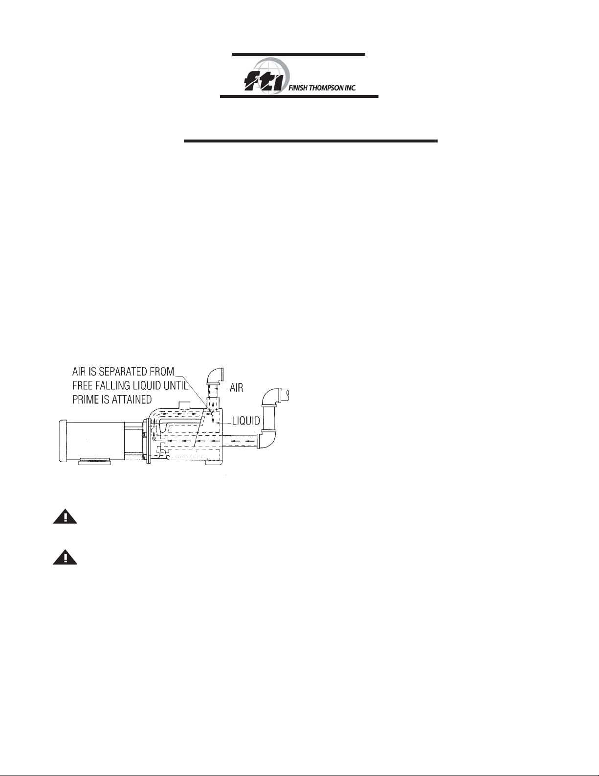
HOW IT WORKS
The MagPrime Chamber is initially filled with liquid. When
the pump is started, recirculating liquid creates a vacuum
in the suction line. This vacuum draws air from the suction line and releases it through the discharge outlet.
When the liquid in the suction line reaches the pump inlet, the pump is primed and normal operation begins (see
Figure 1).
Figure 1Figure 1
Figure 1
Figure 1Figure 1
SAFETY PRECAUTIONS
WARNING: Read this instruction manual com-pletely
before installing and operating this unit. Fail-ure to follow
these precautions can result in serious bodily injury.
WARNING: Magnetic field hazard. This pump contains
powerful rare earth magnets. When the pump is disassembled
(not connected to a motor) and the magnets are exposed,
these magnets produce powerful magnetic fields. Individuals
with cardiac pacemakes, implanted defibrillators, other
electronic medical devices, metallic prosthetic heart valves,
internal wound clips (from surgery), metalic prosthetic
devices or sickle cell anemia must not handle or be int he
proximity of the magnets contained
• Wear proper eye and skin protection when installing,
operating, and maintaining this equipment.
• All electrical wiring (e.g., motor) should be performed
by a qualified electrician.
• Never use this pump for flammables or combustibles.
• Verify chemical compatibility of the pump’s materials
of construction with the liquid being pumped.
o
• Maximum liquid temperature is 120
F (49oC).
INSTALLATION
The MagPrime Chamber comes complete with housing
gasket and hardware. The user must supply 1-1/2” rigid
suction piping and 1-1/4” discharge piping. The suction
inlet is located at the front of the priming chamber.
SECTION 1 - INSTALLATION OF MAGPRIME
CHAMBER FOR AN EXISTING KC11 PUMP
1. Remove any piping from the pump impeller housing.
2. Remove the (5) 1/4- 20 x 1” bolts and (4) Phillips pan
head screws from the impeller housing.
3. Gently tap the impeller housing’s discharge outlet
(using rubber mallet) to remove the impeller housing.
4. Save the impeller housing - DO NOT DISCARD. It is
necessary for pump assembly and disassembly.
5. Remove the old housing o-ring (item 7) from the pump
barrier (item 8) and discard.
6. Install the new housing o-ring (supplied with MagPrime Chamber) onto the pump barrier.
7. Verify that the white ceramic thrust washer is firmly
seated into the MagPrime Chamber.
8. Install the MagPrime Chamber by aligning the groove
in the MagPrime Chamber with the ridges on the
KC11 barrier. Press in place until firmly seated.
9. Install the (5) 1/4-20 x 1-3/4” hex bolts, washers and
nuts (supplied with the MagPrime Chamber). The
nuts will insert into the back tabs on the motor adapter
(item 13). Tighten each bolt to between 30 and 35
in.-lbs. (3.4 and 4.0 Nm) using star pattern sequence
(shown in Figure 2 of the KC11 Series Installation
and Maintenance Instructions). Do not overtighten.
NOTE: Periodic retightening of the bolts is required.
The bolts will loosen from vibration and the expansion/contraction of the plastic parts.
10. Firmly support the motor, prime chamber and piping.
Shim as necessary. Important: Failure to support
these items will result in damage to the pump.
1
Page 2
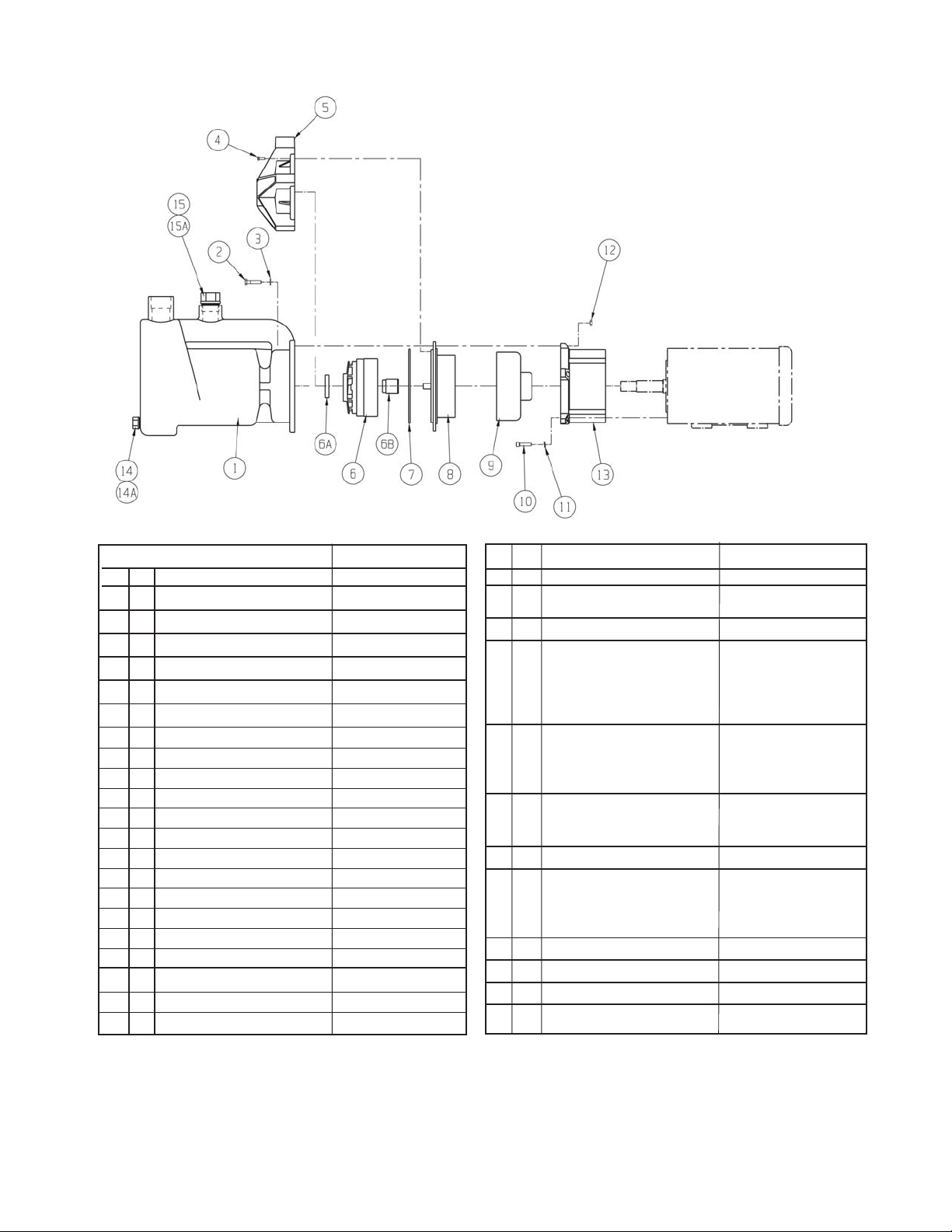
Pump Material
Item Qty Description Polypropylene CF PVDF
1 1 MagPrime Chamber Assembly A101556
2 5 SS Hex Head Cap Screw J102279
3 5 SS Flat Washer J100113
4 4 Phillips Head Screw J101020
5 1 KC11 Impeller Housing A101014-1 A101014-2
6 1 Impeller Hub w/carbon bushing -3” A101931 A101939
Impeller Hub w/PTFE bushing - 3” A101935 A101943
Impeller Hub w/ceramic bushing - 3” A103109 A103113
Impeller Hub w/carbon bushing - 3.5” A101930 A101938
Impeller Hub w/PTFE bushing - 3.5” A101934 A101942
Impeller Hub w/ceramic bushing - 3.5” A103108 A103112
Impeller Hub w/carbon bushing - 4.0” A101929 A101937
Impeller Hub w/PTFE bushing - 4.0” A101933 A101941
Impeller Hub w/ceramic bushing - 4.0” A103107 A103111
Impeller Hub w/carbon bushing - 4.5” A101928 A101936
Impeller Hub w/PTFE bushing - 4.5” A101932 A101940
Impeller Hub w/ceramic bushing - 4.5” A103106 A103110
6A 1 PTFE thrust ring J101606
6B 1 Carbon bushing only J100977
PTFE bushing only J100977-1
Ceramic bushing only J100977-2
Pump Material
Item Qty Description Polypropylene CF PVDF
7 1 Viton o-ring J102774
1 EPDM o-ring J102775
8 1 KC11 Barrier Assembly A101008-1 A101008-2
9 1 Drive Magnet Assembly
- fits 56C motors A101019-1
- fits 145TC motors A101019-2
- fits 80 frame motors A101019-3
- fits 90 frame motors A101019-4
10 4 SS Socket Head Cap Screws
- U.S. J101000
- Metric (80 frame) J101080
- Metric (90 frame) J101081
11 4 SS Lock Washers
- Metric (80 frame) J100672
- Metric (90 frame) J102282
12 4 SS Hex Nut J100321
13 1 Motor Adapter
- U.S. M101629-1
- Metric (80 frame) M101629-2
- Metric (90 frame) M101629-3
14 1 1/2” Pipe Plug J102183
14A 1 O-ring J102280
15 1 1” Pipe Plug J102187
15A 1 O-ring J102281
2
Page 3

11. Plumb the pump into your system. Use only 1-1/2”
rigid piping on the suction side. Important: Suction
piping must be raised approximately 7” (18 cm) above
the center line of the suction inlet on the MagPrime
Chamber (see Figure 2). This ensures proper priming
and pump operation.
Figure 2Figure 2
Figure 2
Figure 2Figure 2
12. Install 1-1/4” rigid piping on the discharge of the
MagPrime Chamber. Important: If the MagPrime
Chamber mounting and piping are not extremely rigid,
leakage can occur and possible pump damage.
TROUBLESHOOTING
If pump does not prime and begin to pump within three
minutes (specific gravity of 1.0 - higher specific gravities
require longer prime times), verify the following:
• No air leaks in suction plumbing.
• Priming chamber filled to proper level.
• The liquid’s specific gravity is not greater than 1.4.
• The impeller is a 4” or 4-1/2” version.
• The motor is at least 2900 rpm and rotating in the
proper direction.
For further troubleshooting, consult the factory.
MAINTENANCE
DISASSEMBLY
1. Drain MagPrime Chamber into an appropriate con-
tainer. Remove the 1/2” pipe plug from front of
MagPrime Chamber. Reinstall plug after draining.
SECTION 2 - INSTALLATION USING NEW KC11 AND
CUSTOMER SUPPLIED MOTOR
1. Install the KC11 pump (not MagPrime Chamber) in
accordance with “KC11 Series Installation and Maintenance Instructions: Assembly Section - steps 1 - 7.”
2. Follow installation steps 2 - 12 from Section 1 of this
manual.
SECTION 3 - INSTALLATION USING NEW KC11
WITH FACTORY SUPPLIED MOTOR
Follow installation steps 2 - 12 from Section 1 of this
manual.
OPERATION
Remove the fill port plug (located on the top of the
MagPrime Chamber). Use approximately 3 quarts (3 liters) of the liquid being pumped to fill the MagPrime
Chamber to capacity. Replace the fill port plug.
CAUTION: Do not allow MagPrime Chamber to overflow.
2. Remove the piping from the suction and discharge
on the MagPrime Chamber.
3. Remove the (5) 1/4-20 x 1- 3/4” bolts from the MagPrime Chamber.
4. Remove the MagPrime Chamber.
CAUTION: Some fluid may leak out when the
chamber is removed.
5. Reinstall the KC11 housing (saved from step 4 in
Section 1 of this manual). Using (4) Phillips pan
head screws, secure the housing to the barrier.
NOTE: Reinstalling the housing allows the impeller
and barrier to be easily and safely removed from the
motor adapter.
6. Remove the impeller and barrier in accordance with
“KC11 Series Installation and Maintenance Instructions: Maintenance Section - Disassembly,” step 4.
7. Follow the steps outlined in the “KC11 Series Installation and Maintenance Instructions: Maintenance
Section - Examination” to check for worn parts.
Replace parts as necessary.
Start the pump. Check all pump components and piping
for leaks.
NOTE: It is critical that the suction piping is air tight. Any
leaks, no matter how small, will prevent the pump from
priming properly.
8. Reassemble following the steps outlined in the “KC11
Series Installation and Maintenance Instructions:
Maintenance Section - Reassembly,” steps 1 - 4.
9. Install wet end following steps outlined in the “KC11
Series Installation and Maintenance Instructions:
Assembly Section,” step 6.
10. Reinstall the MagPrime Chamber following installation steps 2 - 12 from Section 1 of this manual.
3
Page 4

WARRANTY
OTHER FTI PRODUCTS
Finish Thompson, Inc (manufacturer) warrants this product to be free of defects in materials and workmanship for
a period of 180 days from date of purchase by original
purchaser. If a warranted defect, which is determined by
manufacturer’s inspection, occurs within this period, it will
be repaired or replaced at the manufacturer’s option, provided (1) the product is submitted with proof of purchase
date and (2) transportation charges are prepaid to the
manufacturer. Liability under this warranty is expressly
limited to repairing or replacing the product of parts thereof
and is in lieu of any other warranties, either expressed or
implied. This warranty does apply only to normal wear of
the product or components. This warranty does not apply
to products or parts broken due to, in whole or in part,
accident, overload, abuse, chemical attack, tampering,
or alteration. The manufacturer accepts no responsibility
for product damage or personal injuries sustained when
the product is modified in any way. If this warranty does
not apply, the purchaser shall bear all cost for labor, material and transportation.
Manufacturer shall not be liable for incidental or consequential damages including, but not limited to process
down time, transportation costs, costs associated with
replacement or substitution products, labor costs, product installation or removal costs, or loss of profit. In any
and all events, manufacturer’s liability shall not exceed
the purchase price of the product and/or accessories.
Drum Transfer Pumps, available in sanitary construction, stainless steel, polypropylene, PVDF, and CPVC,
are capable of flows to 40 gpm, discharge head to 80
feet and viscosities to 100,000+ cps.
Portable Mixers for turbine mixing and blending handle
viscosities to 1,000 cps with gentle, non-vortexing circulation. Available in 316 stainless steel.
Centrifugal Pumps, in polypropylene, PVDF, 316 stainless steel, and cast iron are offered in mag drive sealless
or mechanical seal models. Pumps are capable of 330
gpm, up to 325 feet discharge head, and 220oF (104oC)
maximum.
For more information, contact Finish Thompson Inc. or
your local distributor.
Call our toll free Technical Service Hot Line, 1-800888-3743, if you have any questions regarding product operation or repair.
ORDERING SPARE PARTS
Spare parts can be ordered from your local distributor.
Always refer to the pump model number to avoid error.
Toll Free Service 800-888-3743
Part Number J103057-1, Rev. 4
FT00-779B, 6/22/06
4
 Loading...