

Page 1
KC 5.5, 6, 6H, 7, 8, & 10 SERIES
Non-Metallic Centrifugal Pumps
Installation and Maintenance Instructions
ASSEMBLY
Unpack the pump, drive magnet assembly and hardware package
from carton and check for shipping damage.
WARNING: Magnetic field hazard. This pump contains powerful
rare earth magnets. When the pump is disassembled (not connected
to a motor) and the magnets are exposed, these magnets produce
powerful magnetic fields. Individuals with cardiac pacemakers,
implanted defibrillators, other electronic medical devices or sickle
cell anemia must not handle or be in the proximity of the magnets
contained inside the pump. Consult a health care provider for specific
recommendations before working with this pump.
ATEX COMPLIANT PUMPS
All assembly, installation, and maintenance instructions are the same
as standard pumps with the exceptions noted on page 4 under “Safety
Precautions for ATEX pumps.”
Figure 1
10A,10B, & 10C) from hardware package.
4. Manually rotate pump assembly to ensure that the pump
is not binding or rubbing on the drive magnet assembly.
5. Install the pump into the system according to installation
instructions.
PUMPS WITH MOTORS
Proceed to Installation Section.
PUMPS WITHOUT MOTORS
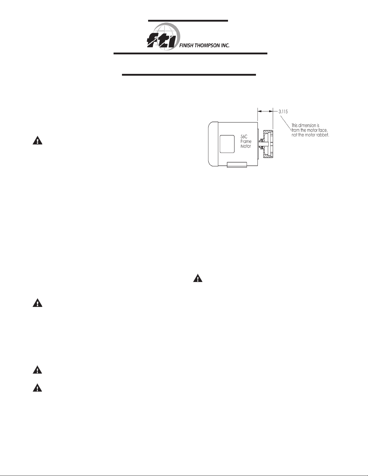
56C frame
1. Remove the pump, drive magnet assembly and hardware
package from box.
CAUTION: Keep away from metallic particles, tools and
electronics. Drive magnets MUST be free of metal chips.
2. Slide drive magnet assembly (item 6) onto the motor shaft
until it is between 3.110” and 3.120” as measured from the
motor face to the top of the drive magnet assembly. See
Figure 1. Align set screw (item 6B) with flat or key slot on
the motor shaft and tighten both setscrews with a 5/32” Al len wrench to 70 in.-lbs. (7.9 N-m ).
CAUTION: Do not operate/test the motor with the drive mag
net assembly exposed.
WARNING: Magnets are strong. To avoid damage and pinch-
ing fingers, tightly grasp pump assembly keeping finger tips
away from the area where the motor adapter and motor meet.
3. Carefully slide the pump assembly over the drive magnet
assembly. Orient the discharge port to either the 12 or
9 o’clock position. Make sure rabbet (step) on motor is fully
seated into the motor adapter (item 5). Align bolt holes in
motor adapter and motor. Install (4) bolts and washers (items
PUMPS WITHOUT MOTORS
63/B14, 71/B14 & 80/B14
1. Remove pump, drive magnet assembly and hardware
package from box.
CAUTION: Keep away from metallic particles, tools
and electronics.
2. Remove screws and washers (items 9A, 9B & 9C) from
impeller housing (item 1) and remove pump assembly
from motor adapter (item 5).
3. For 63 frame pumps - Adjust the single setscrew located in
the middle of the supplied shaft adapter so that it protrudes
slightly into the inside bore. Align that protruding setscrew
with the keyway or flat on the motor shaft and slide on the
shaft adapter until it bottoms out. Tighten the single set-
screw into the keyway, and then tighten the two setscrews
on the end of the adapter onto the motor shaft.
4. Install the motor adapter (item 5) onto the motor with the
access holes top and bottom. Secure with supplied hard-
ware (items 10A, 10B, and 10C). On 63 frame pumps,
from the motor side, insert the supplied gray spacer into the
base of the motor adapter and secure both to the motor.
5. For 63 frame pumps - Screw the cone point drive magnet
assembly setscrew (item 6B) in so that it protrudes
slightly into the drive bore. Align the protruding setscrew point
1
Page 2
.
with the key slot on the shaft adapter and slide the drive
magnet assembly (item 6) on. Adjust the drive magnet
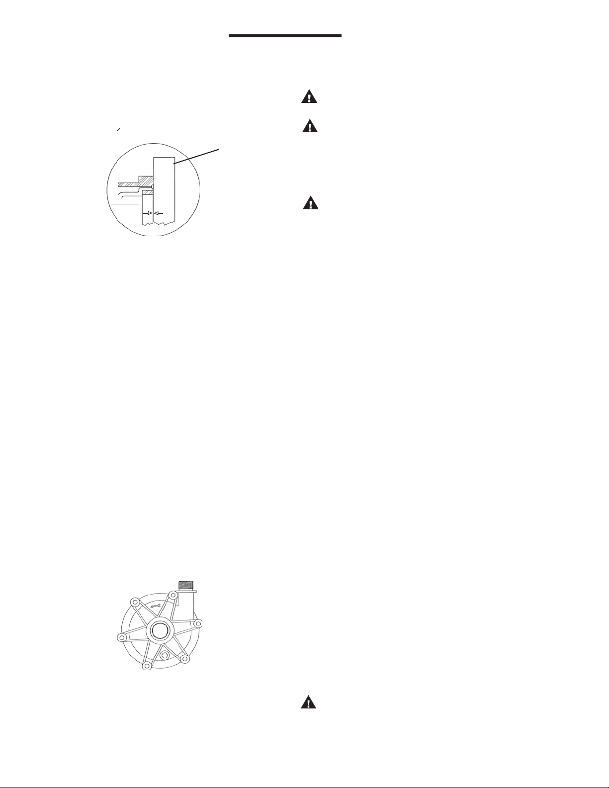
assembly (item 6) so that it is 1.016 mm (.040 +/- .005)
below the face of the motor adapter (see figure 2) and
tighten both setscrews with a 5/32” Allen wrench to 7.9 N.m
(70 in. lbs.).
STRAIGHT
EDGE
DRIVE
MAGNET
ASSY.
.040
Figure 2
For 71 and 80 frame - Align the cone point set screw (item
6B) on the motor shaft and slide the drive magnet assembly
(item 6) onto the motor shaft. Adjust the drive so that it is
1.016 mm (.040 + or -.005) below the face of the motor
adapter (see figure 2). Tighten both setscrews with a 5/32”
Allen wrench to 7.9 N-m (70 in-lbs.).
6. Place the impeller assembly (comprised of items 2 and 3) in
barrier (item 4). Grasping the barrier at opposite bolt tabs,
carefully lower the barrier assembly into the motor adapter/
drive assembly. Line up the tabs of the barrier between the
tabs on the motor adapter to avoid pinching fingers. Once
seated, rotate the barrier until bolt holes line up.
7. Install the o-ring (item 7) on the barrier. Lubricate the o-ring
with a compatible lubricant to facilitate installation.
8. Place the impeller housing (item 1) on the barrier being
careful not to dislodge the o-ring.
9. Align mounting holes and install 6 mounting screws and
washers (items 9A, 9B & 9C) from hardware package. Hand-
tighten screws using pattern shown in Figure 3.
Manually rotate the pump assembly to ensure that the pump
is not binding or rubbing on the drive magnet assembly.
10. Install pump into the system according to installation
instructions.
CAUTION: Do not operate/test the motor with the drive magnet
assembly exposed.
CAUTION: Drive magnets MUST be free of metal chips.
Note: Prior to start-up, double check the two set screws to assure that they are firmly tightened. Failure to do so could result
in internal damage. Rotate to assure clearance with the motor
adapter.
WARNING: Magnets are strong. To avoid damage and
pinching fingers, tightly grasp pump assembly keeping
finger tips away from the area where the housing and
motor adapter meet.
INSTALLATION
MOUNTING
Motor should be securely fastened.
PIPING
1. Support piping near the pump to eliminate any strain on
the pump casings.
2. Do not overtighten the piping on the discharge on initial
installation (i.e., down to the o-ring). Damage to the
discharge can occur. The o-ring is used only when there
is wear and the plastic threads are loose.
3. To minimize head loss from friction:
a. Increase pipe size by 1 diameter.
b. Use minimal number of pipe bends.
4. Keep bends and valves a minimum of 10 pipe diameters from
the suction and discharge.
5. Position pump as close to the liquid source as possible.
6. Maintain a flooded suction (liquid above pump prior to
being primed).
7. Ensure that the piping does not leak and suction is not
prone to clogging.
8. If flexible hose is preferred, use a reinforced hose rated for the
1
3
6
5
proper temperature and pressure. This helps avoid collapse or
kinks.
9. Install valves on suction and discharge lines (a minimum of 10
pipe diameters from the pump).
10. For units in a suction lift system, install appropriate piping in
the discharge to allow priming of the pump.
2
Figure 3
4
11. The suction valve should be completely open to avoid
restricting suction flow.
CAUTION: To stop the pump if prime is lost, use one of the
following: (1) pressure switch on the discharge, (2) vacuum
switch on the suction, (3) a motor minder to monitor motor
current.
2
Page 3
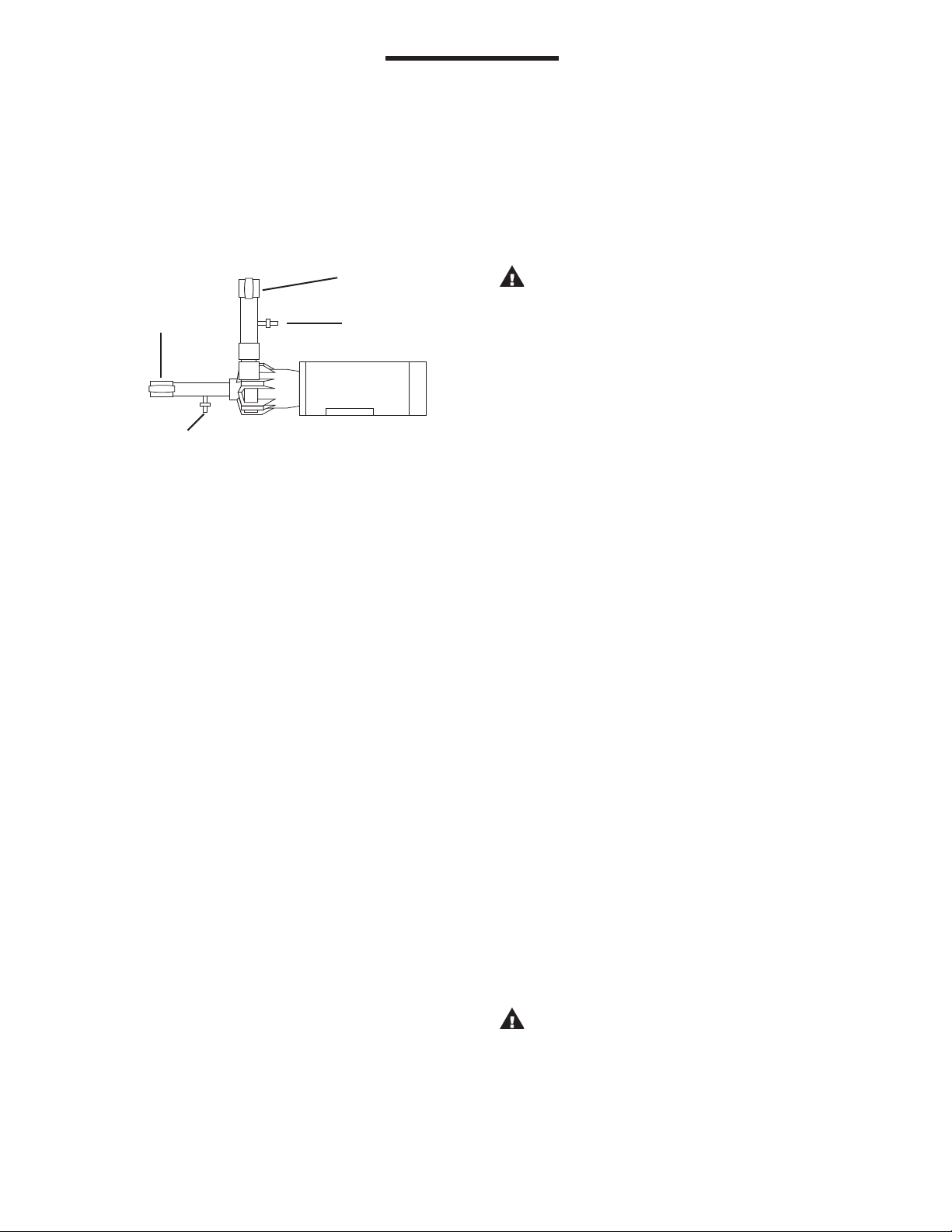
12. When pumping liquids that may solidify or crystallize, a
flush system should be added to the piping. See Figure 4.
Install water inlet and outlet valves as shown.
Note: This pump is provided with a provision for a customer
installed 1/4” NPT drain in the impeller housing. See Drain
Installation Section for details.
SUCTION LIFT SYSTEM
1. Prime the system by filling the priming chamber and/or
suction line with a liquid. Allow time for trapped air to
work its way out.
2. If priming via filling the suction line, close the discharge
valve prior to returning the suction line to the tank.
Figure 4
Discharge Valve
Suction
Valve
Water
Outlet
Valve
Water Inlet Valve
ELECTRICAL
1. Install the motor according to NEC requirements and local
electrical codes. The motor should have an overload protection
circuit.
2. Wire the motor for clockwise rotation when facing the fan
end of the motor.
3. To verify correct rotation of the motor:
a. Install the pump into the system.
b. Fully open the suction and discharge valves
c. Allow fluid to flow into the pump. Do not allow the pump
to run dry (PTFE and ceramic bushings can’t be run dry
without damage to pump components).
d. Jog the motor (allow it to run for only one to two
seconds) and observe the rotation of the motor fan.
Refer to the directional arrow on the pump if needed.
Note: A pump running backward will pump but at a
greatly reduced flow and pressure.
OPERATION
FLOODED SUCTION SYSTEM
1. Completely open suction and discharge valves
2. Start the pump and check liquid flow. If there is no flow,
see the Troubleshooting section.
3. Adjust the flow rate and pressure by regulating the dis-
charge valve. Do not attempt to adjust the flow with the
suction valve.
FLUSH SYSTEMS
CAUTION: Some liquids react with water.
1. Completely close suction and discharge valves.
2. Connect water supply to water inlet valve.
3. Connect drain hose to water valve.
4. Open inlet and outlet valves. Flush system until pump is
clean (approximately 5 minutes).
MAINTENANCE
DISASSEMBLY
1. Disconnect power. Remove electrical wiring and motor
mounting bolts.
2. Close suction and discharge valves. Disconnect piping.
3. Securely hold or clamp the motor in place.
4. For metric pumps, skip to step 5. For 56C frame pumps,
remove the four motor adapter bolts (items 10A, 10B, &
10C) and pull the pump end straight off of the motor
face. Place the pump end on the table with the adapter
flange on the table and the suction pointing straight up.
5. Remove the six housing bolts (item 9A, 9B, & 9C) from
the pump.
6. Using a thin bladed screwdriver, gently separate the im-
peller housing (item 1) from the barrier (item 4). Re-
move the housing o-ring (item 7). Gently separate the
barrier from the motor adapter (item 5). On metric
pumps, carefully separate and rotate the barrier tabs so
that they are located in between the motor adapter bolt
holes. Gripping the tabs, pull the barrier and impeller
assembly from the pump. Remove the impeller assembly
(items 2 and 3) from the barrier.
7. Remove the drive magnet assembly (item 6) using a 5/
32” hex wrench on the two set screws. Metric pumps
have access holes in the motor adapter to loosen set
screws.
CAUTION: Keep the drive magnet and impeller assem-
blies away from metal chips or particles.
EXAMINATION:
1. Check impeller drive bushing (item 3A), thrust ring, ce-
ramic thrust ring and shaft for cracks, chips, scoring or
excess wear. See Figure 5. Replace as required.
3
Page 4

2. Check for loose magnets on drive assembly or rubbed
areas on impeller or barrier assemblies. Contact your
distributor or FTI Technical Service if a problem is found.
3. If you did not remove the drive magnet assembly, check
the set screws for tightness before reassembly.
.020” min.
2. For metric pumps - Follow assembly instructions for metric
pumps on page 1, steps 3 through 10.
Note: Plastic pumps will expand and contract with tem-
perature, so periodically check and hand tighten screws.
This pump is designed to accept an o-ring on the discharge
flange and inlet chamfer as a backup to the NPT or BSP
threads to ensure leak-free operation after temperature
cycling.
OPTIONAL DRAIN INSTALLATION SECTION
1. Remove the impeller housing from the pump assembly.
Figure 5
.415” max.
BUSHING REPLACEMENT
1. To remove the bushing, insert a 1/16” pin punch into bal-
ance hole (inner circle of 4 holes) of impeller assembly
(items 2 & 3). Gently tap the bushing out of the back of the
impeller assembly. The punch may need to be moved to
a different hole if the bushing is difficult to remove.
2. To replace the bushing, clean the impeller bore. Insert
the new bushing into the back of the impeller assembly
by aligning the bushing with the impeller bore. Press
gently until the bushing bottoms out (use a block of wood
and mallet if necessary).
REASSEMBLY
1. 56C pumps - Insert the barrier (item 4) into the motor
adapter (item 5). Align the barrier tabs with the motor
adapter bolt holes and press/pop into place. Install the
impeller assembly (items 2 and 3) into the barrier. Lubricate
the housing o-ring (item 7) with a chemically compatible
lubricant and install. Carefully place the impeller housing
(item 1) onto the barrier, lining up the discharge with a set
screw access hole (top) in the motor adapter. Be careful not
to dislodge the o-ring. Install the six bolts and washers
(items 9A, 9B, and 9C) and hand tighten the screws follow ing the pattern shown in figure 3.
After verifying the setting and setscrews tension on the
drive magnet assembly, grip the pump end by the dis charge and the opposing front edge of the motor adapter
and install the pump end on to the motor. Secure to the
motor with correct hardware (items 10A, 10B, and 10C).
CAUTION: Do not allow fingers between the motor face
and the motor adapter.
2. Clamp the impeller housing to a drill press table.
3. Using a 7/16” drill and the molded boss as a guide, drill
completely through the molded boss into the interior of
the impeller housing. De-burr the hole on the inside of
the impeller housing. See Figure 6.
CAUTION: Do not tap too deep or the impeller housing
may be damaged.
4. Using a 1/4” NPT tap, tap the hole in the molded boss to
the appropriate depth.
5. Install drain plug or valve, being careful not to overtighten.
Figure 6
Drain fitting molded boss.
Use as a guide for drill ing
and tapping 1/4” NPT.
SAFETY PRECAUTIONS FOR ATEX PUMPS
CAUTION: Proper o-ring material must be chosen for the fluid
being pumped. Improper material selection could lead to swelling
and be a possible source of leaks. This is the responsibility of the
end user.
WARNING: The pump must be checked for leaks on a regular
basis. If leaks are noticed, the pump must be repaired or replaced
immediately.
WARNING: The pump must be cleaned on a regular basis to
avoid dust buildup greater than 5 mm.
WARNING: ATEX pumps must use a power monitor, flow
switch, pressure switch or similar device to help protect against
dry running, closed discharge valve and de-coupling. Any of these
conditions could lead to a rise in surface temperature of the pump.
4
Page 5

TEMPERATURE CLASSIFICATION
Maximum
Maximum Allowable
The surface temperatures of the KC ATEX Series pumps depend upon the temperature of the fluid that is being pumped.
Fluid Surface Temperature Surface
Temperature Temperature Class Temperature
The following chart lists different fluid temperatures and the
corresponding pump surface temperatures:
80oF (27oC) 122oF (50oC) T6 85oC
185oF (85oC) 192oF (89oC) T4 135oC
220oF (104oC) 248oF (120oC) T3 200oC
KC5.5, 6, 6H, 7, 8, 10 EXPLODED VIEW
5
Page 6

KC 5.5, 6, 6H, 7, 8, 10 Spare Parts
Item Description Part Number
Impeller Housing with Thrust Ring
KC5.5, 6, 6H NPT - polypropylene A101981-1
KC5.5, 6, 6H NPT - PVDF A101981-3
KC5.5, 6, 6H BSP - polypropylene with FKM o-ring A101982-3
KC5.5, 6, 6H BSP - PVDF with FKM o-ring A101982-4
KC5.5, 6, 6H BSP - polypropylene with EPDM o-ring A101982-7
1
2
2A
3
KC5.5, 6, 6H BSP - PVDF with EPDM o-ring A101982-8
KC7, 8,10, NPT - polypropylene A101981-7
KC7, 8,10, NPT - PVDF A101981-9
KC7, 8,10, BSP - polypropylene with FKM o-ring A101982-11
KC7, 8,10, BSP - PVDF with FKM o-ring A101982-12
KC7, 8,10, BSP - polypropylene with EPDM o-ring A101982-15
KC7, 8, 10, BSP - PVDF with EPDM o-ring A101982-16
Impeller Head Assembly with Thrust Ring
KC5.5 polypropylene - 3.00” A101983-10
KC5.5 PVDF - 3.00” A101983-11
KC6 polypropylene - 3.19” A101983-1
KC6 PVDF - 3.19" A101983-4
KC6H polypropylene - 3.88" A101983-13
KC6H PVDF - 3.88" A101983-14
KC7 polypropylene - 3.19" A101983-15
KC7 PVDF - 3.19" A101983-16
KC8 polypropylene - 3.50" A101983-2
KC8 PVDF - 3.50" A101983-5
KC10 polypropylene - 3.88" A101983-3
KC10 PVDF - 3.88" A101983-6
PTFE Thrust Ring
KC5.5, 6 J102388
KC6H J104045
KC7 J103893
KC8, 10 J101606
Impeller Hub with Bushing
6 pole - polypropylene with carbon bushing A102746-1
6 pole - polypropylene with PTFE bushing A102746-10
6 pole - polypropylene with ceramic bushing A102746-20
6 pole - PDVF with carbon bushing A102746-2
6 pole - PVDF with PTFE bushing A102746-13
6 pole - PVDF with ceramic bushing A102746-21
8 pole - polypropylene carbon bushing A102746-4
8 pole - polypropylene with PTFE bushing A102746-11
8 pole - polypropylene with ceramic bushing A102746-22
8 pole - PVDF with carbon bushing A102746-5
8 pole - PVDF with PTFE bushing A102746-14
8 pole - PVDF with ceramic bushing A102746-23
10 pole - polypropylene with carbon bushing A102746-7
10 pole - polypropylene with PTFE bushing A102746-12
10 pole - polypropylene with ceramic bushing A102746-24
10 pole - PVDF with carbon bushing A102746-8
10 pole - PVDF with PTFE bushing A102746-15
10 pole - PVDF with ceramic bushing A102746-25
12 pole - polypropylene with carbon bushing A102746-16
12 pole - polypropylene with PTFE bushing A102746-17
12 pole - polypropylene with ceramic bushing A102746-26
12 pole - PVDF with carbon bushing A102746-18
12 pole - PVDF with PTFE bushing A102746-19
12 pole - PVDF with ceramic bushing A102746-27
6
Page 7

KC 5.5, 6, 6H, 7, 8, 10 Spare Parts - cont.
Item Description Part Number
Impeller Bushing
3A
Carbon J102387
PTFE J102790
Ceramic J103617
Barrier with Ceramic Shaft & Silicon Carbide Thrust Washer
4
PP A101703-1
PVDF A101703-2
Motor Adapter
56C frame A101991-3
63 frame A101991-8
5
63 frame ATEX (PVDF) A101991-11
71 frame A101991-1
71 frame ATEX (PVDF) A101991-10
80 frame A101991-2
80 frame ATEX (PVDF) A101991-9
Drive Magnet Assembly
6 pole - 56C frame A101990-3
6 pole - 63 frame A101990-11
6 pole - 71 frame A101990-1
6 pole - 80 frame A101990-2
8 pole - 56C frame A101990-6
8 pole - 63 frame A101990-12
6
8 pole - 71 frame A101990-4
8 pole - 80 frame A101990-5
10 pole - 56C frame A101990-7
10 pole - 71 frame A101990-8
10 pole - 80 frame A101990-9
12 pole - 56C frame A101990-15
12 pole - 63 frame A101990-16
12 pole - 71 frame A101990-13
12 pole - 80 frame A101990-14
6A
6B
Set Screw
5/16" knurled J104219
Set Screw
5/16" cone point J104220
Housing O-ring
7
FKM J102389
EPDM J102585
Discharge O-ring
KC5.5, 6 - BSP - FKM J102390
8
KC5.5, 6 - BSP - EPDM J102712
KC7, 8,10 - BSP - FKM J102391
KC7, 8,10 - BSP - EPDM J102713
9A
9B
9C
Impeller Housing Bolts
Stainless steel J102484
Impeller Housing Lock Washers
Stainless steel J100672
Impeller Housing Flat Washers
Stainless steel J100113
Motor Adapter Bolts
10A
56C frame J100114
71, 80 frame J102884
63 frame J103198
Motor Adapter Lock Washers
10B
56C frame J100115
71, 80 frame J100672
63 frame J100672
7
Page 8

KC 5.5, 6, 6H, 7, 8, 10 Spare Parts - cont.
Item Description Part Number
10C
10C
11
Motor Adapter Flat Washer
3/8" stainless steel J100128
Flat Washer
1/4" stainless steel J100113
Plug
For motor adapter J102878
8
Page 9

TROUBLESHOOTING
GENERAL NOTES:
1. Do not pump liquids containing metal fines.
2. Orient the discharge port to either 12 or 9 o’clock position.
3. If magnets de-couple, stop the pump immediately. The rare
earth magnets used in this pump are more resistant to
demagnetization than ceramic magnets, but operating the
pump with the magnets de-coupled will eventually weaken
the magnets.
4. Plastic pumps will expand and contract with temperature so peri odically check and hand-tighten screws. This pump is designed
to accept an o-ring on the discharge flange and inlet chamfer
as a backup to the NPT or BSP threads to ensure leak-free
operation after temperature cycling.
5. Fitting o-rings on discharge flange and inlet chamfer is
possible.
NO DISCHARGE
1. Air leaks in suction piping.
2. Pump not primed.
3. Discharge head too high.
4. Suction lift too high or insufficient NPSHA. Suction lift should
be 2 feet above NPSHR.
5. Closed valve.
6. Viscosity or specific gravity too high (magnets uncoupled).
INSUFFICIENT DISCHARGE
1. Air leaks in suction piping.
2. Discharge head higher than anticipated.
3. Suction lift too high or insufficient NPSHA. Suction lift should be
2 feet above NPSHR.
4. Clogged suction line, foot valve or crimp in hose.
5. Foot valve too small.
6. Foot valve or suction opening not submerged enough.
7. Incorrect pump rotation.
INSUFFICIENT PRESSURE
1. Air or gasses in liquid.
2. Impeller diameter too small.
3. Discharge head higher than anticipated.
4. Incorrect pump rotation.
LOSS OF PRIME
1. Leaking suction or discharge line.
2. Suction lift too high or insufficient NPSHA. Should be 2 feet
above NPSHR.
3. Air or gasses in liquid.
4. Foreign matter in impeller.
5. Leaking valve.
EXCESSIVE POWER CONSUMPTION
1. System head lower than rating. Pumps too much liquid.
.
2. Specific gravity or viscosity of liquid pumped is too high or
higher than that defined in application.
3. Binding pump parts.
VIBRATION/NOISE
1. Excess bearing wear.
2. Drive magnet uncoupled.
3. Loose magnet.
4. Pump cavitation.
5. Motor or piping not properly secured.
6. Foreign object in impeller.
WARRANTY
Finish Thompson Inc. warrants this pump product to be free of defects
in materials and workmanship for a period of one year from date of
purchase by original purchaser. If a warranted defect occurs, which
is determined by manufacturer’s inspection, within this period, it will
be repaired or replaced at the manufacturer’s option, provided (1) the
product is submitted with proof of purchase date and (2) transportation charges are prepaid to the factory. Liability under this warranty is
expressly limited to repairing or replacing the product or parts thereof
and is in lieu of any other warranties, either expressed or implied. This
warranty applies only to normal wear of the product or components.
This warranty does not apply to products or parts broken due to, in
whole or in part, accident, overload, abuse, chemical attack, tampering, or alteration. The warranty does not apply to any other equipment
used or purchased in combination with this product. The manufacturer
accepts no responsibility for product damage or personal injuries
sustained when the product has been modified or altered in any way. If
this warranty does not apply, the purchaser shall bear all costs for labor,
material, and transportation.
Manufacturer shall not be liable for incidental or consequential damages including, but not limited to, process down time, transportation
costs, costs associated with replacement or substitution products, labor
costs, product installation or removal costs, or loss of profit. In any and
all events, manufacturer’s liability shall not exceed the purchase price of
the product and/or accessories.
CHEMICAL REACTION DISCLAIMER
The user must exercise primary responsibility in selecting the product’s materials of construction, which are compatible with the fluid(s)
that come(s) in contact with the product. The user may consult Finish
Thompson, Inc. (manufacturer) and a manufacturer’s representative/
distributor agent to seek a recommendation of the product’s material of
construction that offers the optimum available chemical compatibility.
However neither manufacturer nor agent shall be liable for product
damage or failure, injuries, or any other damage or loss arising out
of a reaction, interaction or any chemical effect that occurs between
the materials of the product’s construction and fluids that come into
contact with the product’s internals.
Service 800-888-3743
J102714, Rev.16, 7./15/2014
FT96-606N
 Loading...