

Page 1
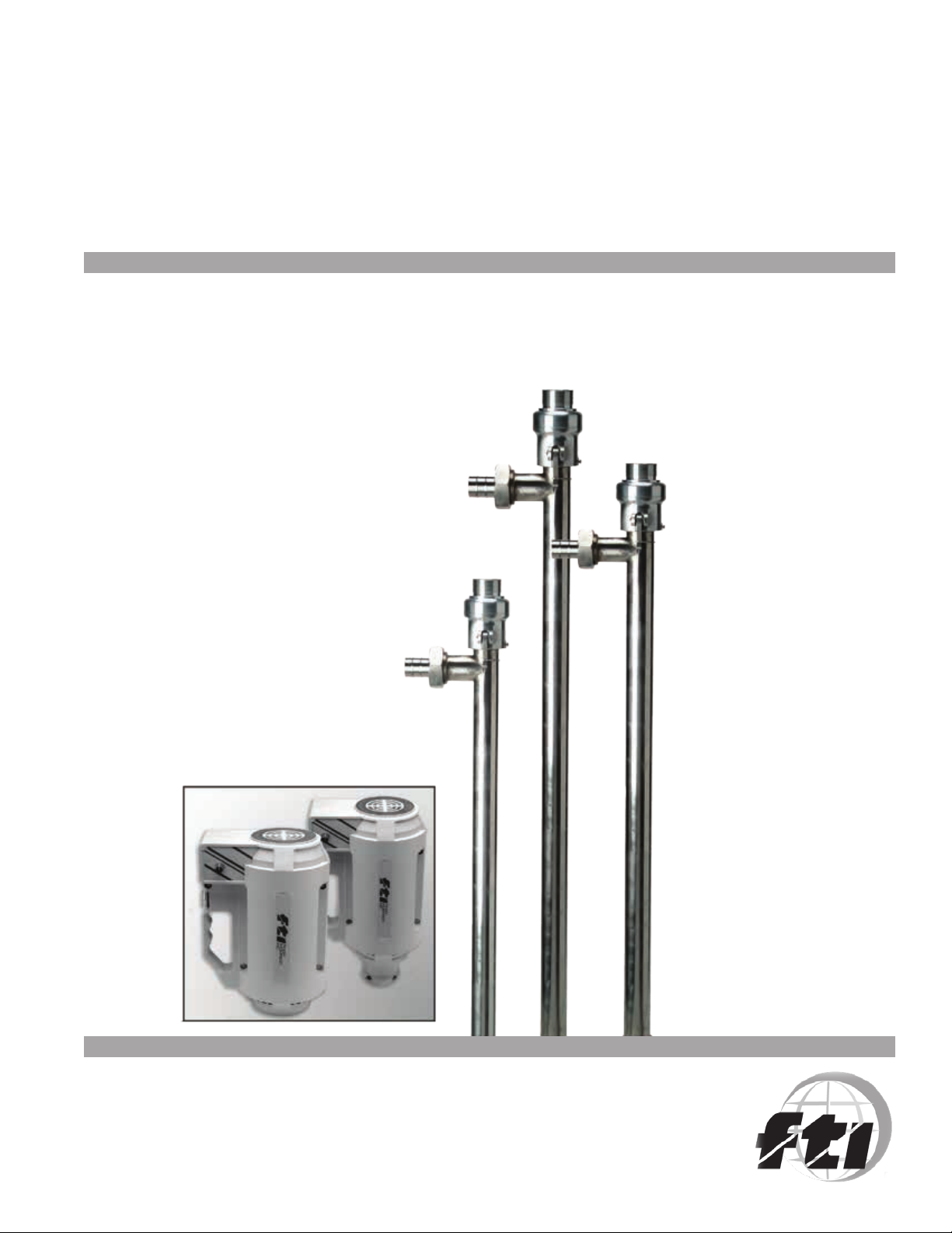
HVDP SERIES
OPERATION AND PARTS MANUAL
DRUM PUMPS AND MOTORS
1
Page 2

TABLE OF CONTENTS
Introduction ....................................................................................................................................................................... 3
Warranty ............................................................................................................................................................................ 3
Chemical Reaction Disclaimer ...........................................................................................................................................3
Return Policy ..................................................................................................................................................................... 3
Safety Precautions ............................................................................................................................................................. 4
Maintenance Precautions ...................................................................................................................................................4
HVDP Terminology ............................................................................................................................................................ 5
HVDP Series Assembly, Maintenance and Assembly ........................................................................................................6
HVDP Series Drive Assembly Removal and Installation .................................................................................................... 7
HVDP Series Rotor Removal, Inspection and Installation ................................................................................................. 7
HVDP Series Stator Removal, Inspection and Installation .................................................................................................8
HVDP Series Seal Removal, Inspection and Installation .................................................................................................... 8
HVDP-HR Series Parts Schematic .....................................................................................................................................9
HVDP-LR Series Parts Schematic ..................................................................................................................................... 10
M58H and M59H 800W Motors Parts Schematic ............................................................................................................. 11
2
Page 3

INTRODUCTION
Finish Thompson is a designer and manufacturer of drum pumps and mixers available worldwide through a qualied,
experienced network of distributors and/or representatives. Drum pump selection is easy with FTI’s complete line of
interchangeable motors and tubes.
WARRANTY
Finish Thompson Inc (manufacturer) warrants this product to be free of defects in materials and workmanship for a period
of one year from date of purchase by original purchaser. If a warranted defect, which is determined by manufacturer’s
inspection, occurs within this period, it will be repaired or replaced at the manufacturer’s option, provided (1) the prod-
uct is submitted with proof of purchase date and (2) transportation charges are prepaid to the manufacturer. Liability
under this warranty is expressly limited to repairing or replacing the product or parts thereof and is in lieu of any other
warranties, either expressed or implied. This warranty does apply only to normal wear of the product or components.
This warranty does not apply to products or parts broken due to, in whole or in part, accident, overload, abuse, chemical attack, tampering, or alteration. The manufacturer accepts no responsibility for product damage or personal injuries
sustained when the product is modied in any way. If this warranty does not apply, the purchaser shall bear all cost for
labor, material and transportation.
Manufacturer shall not be liable for incidental or consequential damages including, but not limited to process down
time, transportation costs, costs associated with replacement or substitution products, labor costs, product installation
or removal costs, or loss of prot. In any and all events, manufacturer’s liability shall not exceed the purchase price of
the product and/or accessories.
CHEMICAL REACTION DISCLAIMER
The user must exercise primary responsibility in selecting the product’s materials of construction, which are compatible
with the uid(s) that come(s) in contact with the product. The user may consult Finish Thompson Inc. (manufacturer)
and/or a manufacturer’s representative/distributor agent to seek a recommendation of the product’s material of construction that offers the optimum available chemical compatibility.
However neither Manufacturer nor agent shall be liable for product damage or failure, injuries, or any other damage or
loss arising out of a reaction, interaction or any chemical effect that occurs between the materials of the products construction and uids that come into contact with the product’s internals.
RETURN POLICY
Should you have any problems with this product, please contact the distributor in your area. The distributor will then
determine if a return to the factory is necessary and will contact the factory for a return authorization number.
3
Page 4

SAFETY PRECAUTIONS
read the installation instructions before operating the pump.
ALWAYS
wear protective clothing, eye protection and follow standard safety procedures when handling corrosive or
ALWAYS
personally harmful materials.
use protective gloves to prevent contact with hot surfaces.
ALWAYS
use an open, splash proof or TEFC motors when pumping or mixing ammable or combustible material.
NEVER
place the pump intake in uid before starting the pump.
ALWAYS
make sure the discharge hose and pump are both secured and properly supported before starting the pump.
ALWAYS
make sure the pump is properly grounded when pumping ammable or combustible materials. This requires
ALWAYS
a static protection kit.
use a discharge hose that is chemically compatible with the uid being pumped and is rated at the discharge
ALWAYS
temperature and pressure of the pump installation.
NEVER use the pump in pressurized containers.
MAINTENANCE PRECAUTIONS
check motor rotation on LR versions (air and induction motors) before installing the motor onto the pump.
ALWAYS
store the pump and motor upright and away from corrosive liquids and vapors.
ALWAYS
check compatibility and temperature range of the pump with the liquids being used.
ALWAYS
ush the unit after each use if the liquid being pumped can crystallize or harden.
ALWAYS
re-lubricate the pump internals after cleaning.
ALWAYS
pump liquids containing solids that can damage internal pump parts (i.e. metal chips).
NEVER
allow the pump to run dry.
NEVER
operate the pump against a closed discharge. If the pump is operated against a closed discharge, a bypass (pres-
NEVER
sure relief valve) must be used.
NOTE: Pumping solid can lead to increased wear on the stator and rotor.
4
Page 5

HVDP TERMINOLOGY
5
Page 6

HVDP SERIES ASSEMBLY, MAINTENANCE & CLEANING INSTRUCTIONS
SECTION 1: MOTOR INSTALLATION AND REMOVAL
INSTALLATION - HVDP-HR
1. Locate the rubber coupling insert that was separately shipped in a plastic bag (see Figure 1).
2. Install the rubber coupling insert onto the metal coupling half located on top of the HR drive
assembly.
3. Find the metal coupling half located inside the HR motor. Align this coupling with rubber insert
installed in the second step of these instructions.
4. Slide the HR motor onto the HR drive assembly.
5. Hand tighten the motor nut onto the threaded nose of the HR motor.
HVDP-HR REMOVAL: To remove the HR motor, reverse HR motor installation instructions
found in this section.
Figure 1
INSTALLATION - HVDP-LR
1. Check the rotation direction of the LR motor.
WARNING: Motor rotation must be clockwise when viewed from the fan end of the motor. Rotating the motor in the wrong direction
will cause damage to the pump.
2. Remove the motor adapter bolts (see Figure 2) and separate the motor adapter from the motor.
3. Thread the motor adapter onto the LR drive assembly. Hand tighten the motor adapter.
Note: Threads are left-handed. Also, thread lubricant is recommended to ensure smooth, bind free assembly.
4. The LR motor coupling consists of two 5/16” diameter pins welded to a hub. The LR drive assembly coupling has two slots that
receive these pins. Align the pins of the motor coupling with the slots on the drive assembly coupling and slide the motor onto
the drive assembly.
Note: Make sure the coupling is engaged properly and the motor adapter face is flush with the motor face.
5. Rotate the motor until the motor adapter mounting holes align with the threaded holes in the motor face.
6. Install the motor adapter bolts and torque to approximately 7 ft.-lbs. (9.5 N•M)
HVDP-LR REMOVAL:
1. Remove the LR motor adapter bolts.
2. Remove the LR motor.
Figure 2
6
Page 7

SECTION 2: STATOR REMOVAL, INSPECTION, AND INSTALLATION
REMOVAL:
1. The stator is located at the bottom of the pump tube assembly (see Figure 5).
2. Remove the stator by unthreading it from the pump tube. If the stator cannot be
unthreaded by hand, insert a screwdriver into the slots found at the bottom of the
stator. Use the screwdriver to rotate the stator.
Note: The stator has left hand threads.
INSPECTION: Inspect the stator for gouging and excessive wear. Contact FTI if you are
questioning the condition of the stator.
INSTALLATION: Reverse the removal instructions found in this section.
Pump
Tube
Assembly
Stator
SECTION 3: DRIVE ASSEMBLY REMOVAL AND INSTALLATION
Figure 5
REMOVAL:
1. Remove the motor (see section 1 and follow the instructions for your model).
2. Remove stator (see section 2).
3. Remove the bail wire (see Figure 3).
4. Release the cam-lock by pulling the cam-lock levers towards the top of the drive assembly.
5. Pull the drive assembly out of the pump tube assembly while holding the cam-lock levers in the upright position.
INSTALLATION:
1. Make sure that the locating stud on the back of the pump tube assembly is aligned with the drive assembly coupling.
2. Push the drive assembly into the pump tube assembly while holding the cam lock levers in the upright position.
3. Rotate the cam-lock levers downward.
4. Install the bail wire.
5. Install stator.
Figure 3
7
Page 8
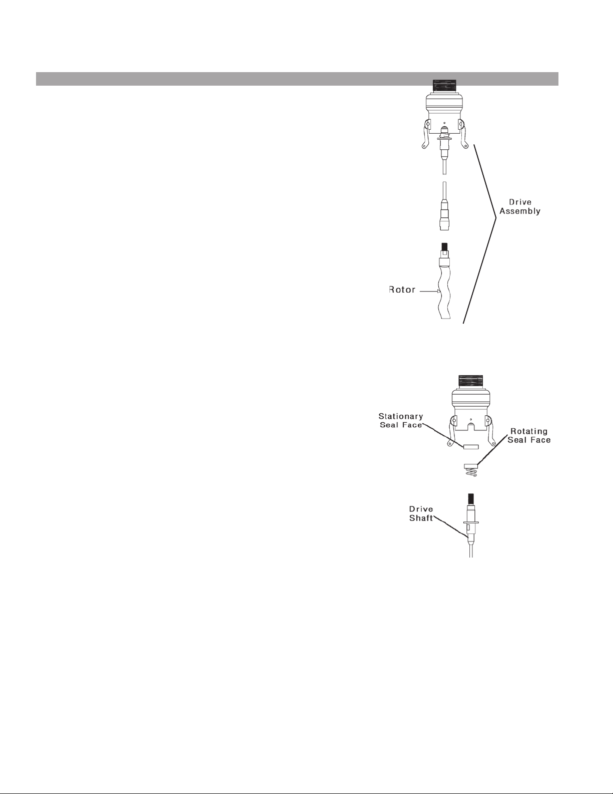
SECTION 4: ROTOR REMOVAL, INSPECTION, AND INSTALLATION
REMOVAL:
1. Remove the motor (see section 1 and follow the instructions for your model).
2. Remove the drive assembly (see section 3).
3. The rotor is located at the bottom of the drive assembly (see Figure 4).
4. Using 3/4” and 5/8” open-end wrenches, loosen and remove the rotor.
INSPECTION: Inspect the rotor for excessive wear and deep grooving. Contact FTI if
you are questioning the condition of the rotor.
INSTALLATION: Reverse the removal instructions found in this section.
SECTION 5: SEAL REMOVAL, INSPECTION, AND INSTALLATION
REMOVAL:
1. Remove the motor (see section 1 and follow the instructions for your model).
2. Remove stator (see section 2).
Figure 4
3. Remove the drive assembly (see section 3).
4. The seal is located at the interface between the gearbox and the drive shaft (see Figure
6).
5. Secure the pump drive coupling using a pair of pliers.
6. Using a 3/4” open-end wrench, separate the drive shaft from the gearbox.
7. Being sure to protect the polished seal-seating area of the shaft, gently remove the
rotating seal boot, spring, and spring retainer.
8. Using a thin bladed screwdriver, remove the stationary component of the seal from
the gearbox assembly.
INSPECTION: Inspect the seal for wear and scratching.
INSTALLATION:
1. Lubricate the outside diameter of the stationary seal with a compatible lubricant and carefully install it into the gearbox housing.
2. Install the spring and spring retainer onto the pump shaft.
3. Lubricate the inside of the rotating seal boot with a chemically compatible lubricant and install it onto the pump shaft.
4. Reverse steps five through one of the seal removal instructions found in this section.
Figure 6
SECTION 6: HELPFUL HINTS FOR CLEANING THE PUMP
After flushing the internal components of the pump, be sure to lubricate the rotor.
8
Page 9

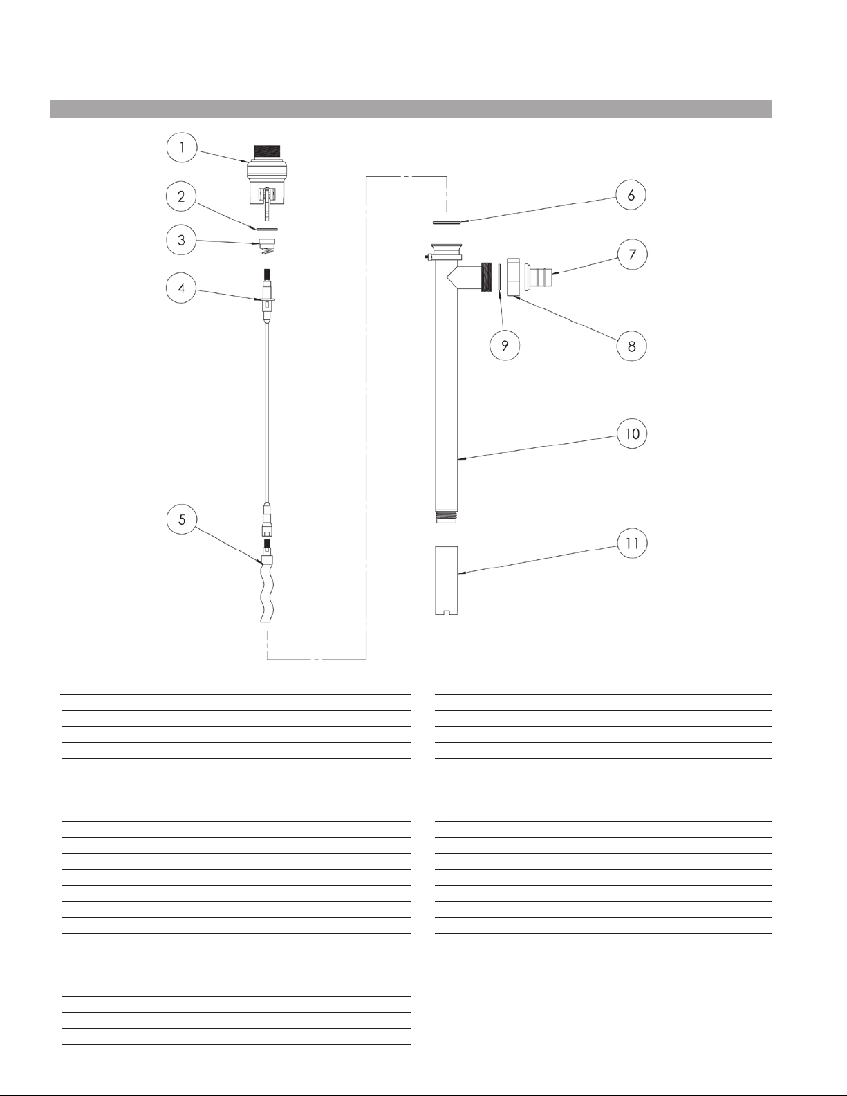
HVDP SERIES - HVDP-HR
ITEM DESCRIPTION PART NUMBER
1 Coupling Insert J100014
2 HVDP-HR Gear Box Assembly 16:1 105150
3 Tube O-ring FKM 105080
3 Tube O-ring EPDM 105081
3 Tube O-ring Buna-FDA 108069
3 Tube O-ring PTFE Encap Sil 105082
4 Seal (carbon/ceramic/FKM) J102957-1
4 Seal (carbon/ceramic/EPDM) J102957-2
4 Seal (carbon/ceramic/Buna-FDA) 108073
4 Seal (carbon/ceramic/Kalrez) J103081
4 Seal (silicon carbide/FKM) J103066
4 Seal (silicon carbide/EPDM) J103067
5 HVDP 27 HR Shaft Assembly 105146-1
5 HVDP 40 HR Shaft Assembly 105146-2
5 HVDP 48 HR Shaft Assembly 105146-3
6 HVDP Rotor #1 105009-1
6 HVDP Rotor #2 105009-2
6 HVDP Rotor #3 105009-3
7 Cplg O-ring FKM 105083
7 Cplg O-ring EPDM 105084
7 Cplg O-ring Buna-FDA 108071
7 Cplg O-ring PTFE Encap Sil 105085
ITEM DESCRIPTION PART NUMBER
8 HVDP Barbed Hose Adapter 1 1/2” 105176
8 HVDP Barbed Hose Adpater 2” 105287
8 HVDP Tri-Clamp Discharge Fitting 107395
9 Union Nut 105023
10 Discharge O-ring FKM 107784
10 Discharge O-ring EPDM 107785
10 Discharge O-ring Buna-FDA 108070
10 Discharge O-ring PTFE Encap Sil 107786
11 HVDP 27 Intake Tube Assembly* 105143-1
11 HVDP 40 Intake Tube Assembly* 105143-2
11 HVDP 48 Intake Tube Assembly* 105143-3
12 HVDP Buna Stator 105008-1
12 HVDP Buna Stator for Foot Option 105456
12 HVDP FKM Stator 105008-2
12 HVDP FKM Stator for Foot Option 105456-1
12 HVDP PTFE Stator 105326
12 HVDP PTFE Stator for Foot Option 105456-2
HVDP Bail Wire (not shown) 105032
*If purchasing or replacing an intake tube, please purchase appropriate o-ring, item 10.
9
Page 10
HVDP SERIES - HVDP-LR
ITEM DESCRIPTION PART NUMBER
1 HVDP LR Gearbox Assembly 5:1 105154
1 HVDP LR Gearbox Assembly 4:1 105155
2 Tube O-ring FKM 105080
2 Tube O-ring EPDM 105081
2 Tube O-ring Buna-FDA 108069
2 Tube O-ring PTFE Encap Sil. 105082
3 Seal (carbon/ceramic/FKM) J102957-1
3 Seal (carbon/ceramic/EPDM) J102957-2
3 Seal (carbon/ceramic/Buna-FDA) 108073
3 Seal (carbon/ceramic/Kalrez) J103081
3 Seal (silicon carbide/FKM) J103066
3 Seal (silicon carbide/EPDM) J103067
4 HVDP 27 LR Shaft Assembly 105147-1
4 HVDP 40 LR Shaft Assembly 105147-2
4 HVDP 48 LR Shaft Assembly 105147-3
5 HVDP Rotor #1 105009-1
5 HVDP Rotor #2 105009-2
5 HVDP Rotor #3 105009-3
6 Cplg O-ring FKM 105083
6 Cplg O-ring EPDM 105084
6 Cplg O-ring Buna-FDA 108071
6 Cplg O-ring PTFE Encap Sil 105085
ITEM DESCRIPTION PART NUMBER
7 HVDP Barbed Hose Adapter 1 1/2” 105176
7 HVDP Barbed Hose Adapter 2” 105287
7 HVDP Tri-Clamp Discharge Fitting 107395
8 Union Nut 105023
9 Discharge O-ring FKM 107784
9 Discharge O-ring EPDM 107785
9 Discharge O-ring Buna-FDA 108070
9 Discharge O-ring PTFE Encap Sil 107786
10 HVDP 27 Intake Tube Assembly* 105143-1
10 HVDP 40 Intake Tube Assembly* 105143-2
10 HVDP 48 Intake Tube Assembly* 105143-3
11 HVDP Buna Stator 105008-1
11 HVDP Buna Stator for Foot Option 105456
11 HVDP FKM Stator 105008-2
11 HVDP FKM Stator for Foot Option 105456-1
11 HVDP PTFE Stator 105326
11 HVDP PTFE Stator for Foot Option 105456-2
* HVDP Bail Wire (not shown) 105032
*If purchasing or replacing an intake tube, please purchase appropriate o-ring, item 9.
10
Page 11

M58H & M59H 800W MOTORS
Quantity
Item M58 M59 Description Part Number
1 1 1 Housing Repair Kit 105144
2 2 2 Ball Bearing J101069
3 1 1 Switch J101143
4 1 1 Half Coupling J100013
5 1 - Cord Assembly A101738
5 - 1 Cord Assembly A101740
6 2 2 Brush Set J101107
7 6 6 Housing Nut J100990
8 6 6 Housing Bolt J100023
9 3 3 Screw J101530
10 1 1 Wave Washer J101126
11 1 - Circuit Breaker J103796
12 - 1 Circuit Breaker J101149
13 1 1 Cover J100789
14 1 1 Fan 105102
15 1 - Speed Control 105136
15 - 1 Speed Control 105062
16 1 1 Speed Control Knob 105063
17 1 1 Gearbox Adapter 105133
11
Page 12
EU Declaration of Conformity
Finish Thompson Inc. hereby declares that the following machine(s) fully comply with the
applicable health and safety requirements as specified be the EC Directives listed.
The product may not be taken into service until it has been established that the drive motor
for the Drum and Container Pump complies with the provisions of all relevant EC Directives.
The complete product complies with the provisions of the EC Directive on machinery safety
provided motors manufactured by Finish Thompson Inc. are used.
This declaration is valid provided that the devices are fully assembled and no modifications
are made to these devices.
Type of Device:
Drum and Container Pump Tubes
Models:
BTS – 40 EPPI/EPPS 15/27/40 EFP/EFV/EFS-16/27/40/48
HVDP LR-27/40/48 HVDP HR-27/40/28 PFM-27/40/48/60
PFP-15/27/40/48/60/72 PFS-27/40/48/60/72 PFV-27/40/48/60/72
TBP-27/40/48 TBS-40 TTC/TTS-27/40/48
STTS-40 TMS-40
EC Directives:
Machinery Safety (2006/42/EC)
Applied Harmonized Standards:
EN ISO 12100 Part 1
EN ISO 12100 Part 2
EN 809
Manufacturer:
Finish Thompson Inc.
921 Greengarden Road
Erie, Pennsylvania 16501-1591 U.S.A
Signed,
_
President
January 7, 2013
Person(s) Authorized to Compile Technical File: Michael Smith Engineers Limited
Oaks Road, Woking, Surrey
GU21 6PH, UK
Telephone: 01483 771871
12
Service 1-800-888-3743
Literature ID No. FT03-875C
P/N 105362, Rev. 4, 2.27.13
 Loading...