

Page 1

GP22/32 SERIES
Sealed Non-Metallic Centrifugal Pumps
Installation and Maintenance Instructions
ASSEMBLY
Unpack pump from carton and check for shipping damage.
PUMPS WITH MOTOR
No assembly required. Simply unpack the pump and motor and
examine for any shipping damage. If damage is detected, save the
packaging and notify the carrier immediately.
Remove the shipping plugs from the suction and discharge of the
pump and proceed to the “Installation Requirements” section of these
instructions.
PUMPS WITHOUT MOTORS
184JM MOTOR ADAPTER (STANDARD)
1. Unpack the pump and examine for any shipping damage. If damage
is detected, save the packaging and notify the carrier immediately.
2. Prepare to install the pump onto the motor.
a. Remove the protective shroud (Item #22) from the
Motor Adapter (item #6).
b. Install key (provided) on keyway of motor and coat with anti-
seize.
3. Align pump impeller shaft with the motor shaft and key, then push
pump onto the motor.
4. Pull the socket head bolt, impeller cap and impeller cap o-ring
(Items #4, 13, 16) from the hardware bag.
a. Install the socket head bolt through the suction of the pump with
a 5/16" hex key. Coat threads of socket head bolt with anti-seize
and tighten in a clockwise rotation. It may be necessary to hold
the motor fan blade with a screwdriver to keep motor shaft from
turning.
b. Install the impeller cap and impeller cap o-ring using a large flat
head screwdriver in a clockwise rotation.
IMPORTANT: Do not cross thread impeller cap or leakage could
occur.
5. Now install motor adapter bolts and washers (Items #12,19) and
tighten securely.
6. Verify back of impeller is not touching the housing cover by looking
into the discharge of the pump.
7. Reinstall protective shroud back onto the motor adapter.
8. Install pump according to installation instructions.
90,100/112 Motor Adapters (Metric)
1. Unpack the pump and examine for shipping damage. If damage is
detected, save the packaging and notify the carrier immediately.
2. Prepare to install the pump onto the motor.
a. Remove the protective shroud (Item #22) from the motor adapter
(item #6).
b. Install key (provided) on keyway of motor and coat with anti-
seize.
3. Align pump impeller shaft with the motor shaft and key, then push
pump onto the motor until it bottoms out.
4. Tighten the two (2) set screws (Item #25) on the motor shaft to 7.9
N•m (70 in•lbs).
5. Now install motor adapter bolts and washers (Items #12,19) and
tighten securely.
6. Verify back of impeller is not touching the housing cover by looking
into the discharge of the pump.
7. Reinstall protective shroud back onto the motor adapter.
8. Install pump according to installation instructions.
INSTALLATION
MOUNTING
Motor or base plate must be securely fastened.
PIPING
• Always support the piping near the pump to minimize stress and
strain on the pump’s casing.
• Minimize frictional losses by increasing the piping size by one
diameter.
• Use a minimal number of bends, keeping any bends at least a
distance of ten pipe diameters away from the pump.
• Install valves on the suction and discharge lines. Place the valves
within a minimum distance of ten pipe diameters away from the
pump.
• Ensure that the piping is leak free.
• Position the pump as close to the liquid source as possible.
• Maintain a flooded suction at all times.
PUMPS WITH COOLING (PRESSURE) COLLARS
A cooling collar provides a water flush to the pump’s seal. This is
necessary when pumping hot liquids or liquids that tend to build up or
crystallize around the seal faces. If your pump is supplied with a cooling collar, proper water flow and pressure are critical to the operation
of the pump.
1. Plumb a water supply to the cooling collar. Use the 1/8” NPT
threaded holes for the water inlet and drain lines. Either hard pipe
or flexible tubing is suitable.
2. Adjust the water flow and pressure of the flush/cooling water
BEFORE starting the pump.
• For pumps with bellows or multi-spring seals, supply
one to two gallons water flow per hour at 1 - 2 psi.
• For pumps with a double seal, supply one to two
gallons water flow per hour at 5 - 10 psi ABOVE the dis-
charge pressure of the pump.
CAUTIONS:
1) Never run a pump equipped with a cooling collar without
a proper water supply. Doing so will result in damage to
the pump. Use of a flow switch is recommended.
2) Do not over pressurize the cooling collar’s water supply.
Doing so can result in damage to pump components.
1
Page 2
2
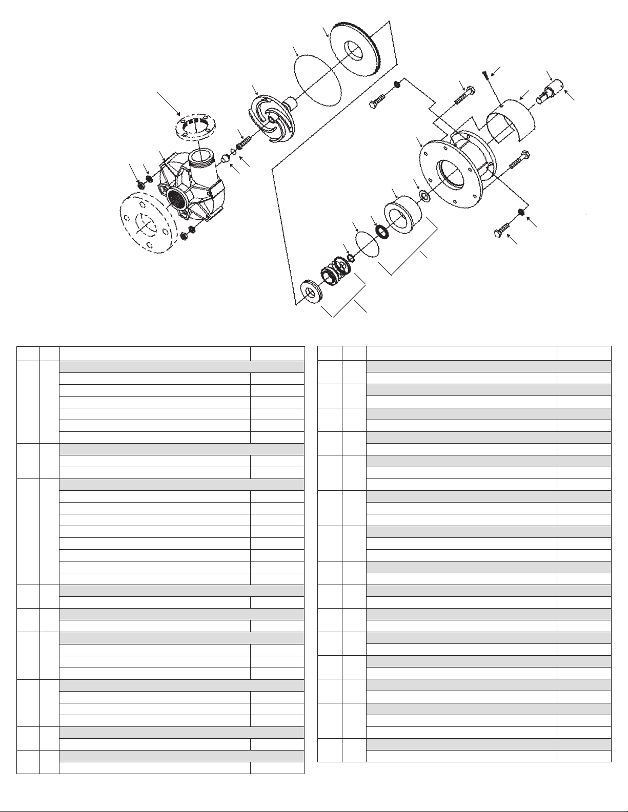
14
GP-32 Flanges
Non-removable
1
11
10
Item Qty. Description Part No.
Impeller Housing
2"x2" NPT, polypropylene (GP22) M100870-1
2"x2" NPT, PVDF (GP22) M100870-2
1
1
2"x2" BSP, polypropylene (GP22) 105388
2"x2" BSP, PVDF (GP22) 105388-1
3"x2" flanged, polypropylene (GP32) A101230-1
3"x2" flanged, PVDF (GP32) A101230-2
Impeller Housing Cover
2
1
Polypropylene M100868-1
PVDF M100868-2
Impeller
6-1/8" - PVDF - bellows/multispring seal models only A101761-1
5" - PVDF - bellows/multispring seal models only A101761-3
5-1/2" - PVDF - bellows/multispring seal models only A101761-2
3
1
4-1/2" - PVDF - bellows/multispring seal models only A101761-4
6-1/8" - PVDF - double seal models only A101761-5
5-1/2" - PVDF- double seal models only A101761-6
5" - PVDF - double seal models only A101761-7
4-1/2" - PVDF - double seal models only A101761-8
4
5
6
7
8
9
Impeller Cap
1
PVDF M100130
Cooling/Press Collar Only
1
Polypropylene - use with double seal pumps M100132
Motor Adapter
NEMA 184JM frame M101569
1
IEC 90 frame M101570-2
IEC 100/112 frame M101570-1
Seals (standard options - call factory for additional options)
Bellows - C/R/V J100122
1
Multispring - C/RH/V J100123
Double - C/RH/V,C/RH/V J100124
Retaining Ring
1
Stainless steel J100125
Hex Head Cap Screw
6
5/16-3 stainless steel J101058
3
13
16
4
23
9
6
18
5
17
15
8
21
7
Item Qty. Description Part No.
10
11
12
13
14
15
16
17
18
19
21
22
23
24
25
Hex Nut
6
5/16-18 stainless steel J101257
Flat Washer
6
5/16 SAE stainless steel J101293
Lock Washer
4
3/8 stainless steel J100115
Hex Head Cap Screw
1
3/8-16 x 1/2 stainless steel J100129
Housing O-ring
1
FKM J101085
EPDM J101086
Cooling Collar O-ring
1
FKM J100118
EPDM J100119
Impeller Cap O-ring
1
FKM J100132
EPDM J100133
Cooling Collar Seal (for use w/ bellows & multispring seals)
1
Lip Seal J100134
Slinger Ring
1
Neoprene M100135
Hex Screw
4
3/8" x 16 x 1" stainless steel (4 required) J100114
Cooling Collar Assembly (for use w/ bellows & multispring seals)
1
w/ FKM o-ring & lip seal A100188
Protective Guard
1
For single seal M100851
Protective Shroud Screw
1
Stainless steel J102112
Shaft Adapter with Set Screws
1
IEC 90 frame A102047
IEC 100/112 frame A102048
Knurled Cup Point Set Screw
4
1/4-20 x 1/4 stainless steel J100220
24
22
25
12
19
2
Page 3
SPECIAL PIPING SITUATIONS
Suction Lift
1. Install a priming chamber on the feed side of the pump or appropriate piping on the discharge for priming the pump.
2. Install a foot valve on the bottom of the suction piping to maintain
a prime to the pump.
CAUTION: Suction prime must be maintained at all times. Running
the pump dry will cause damage to pump components. To protect
the pump if prime is lost, use a pressure switch on the discharge,
a vacuum switch on the suction, or a motor minder to monitor
motor current draw.
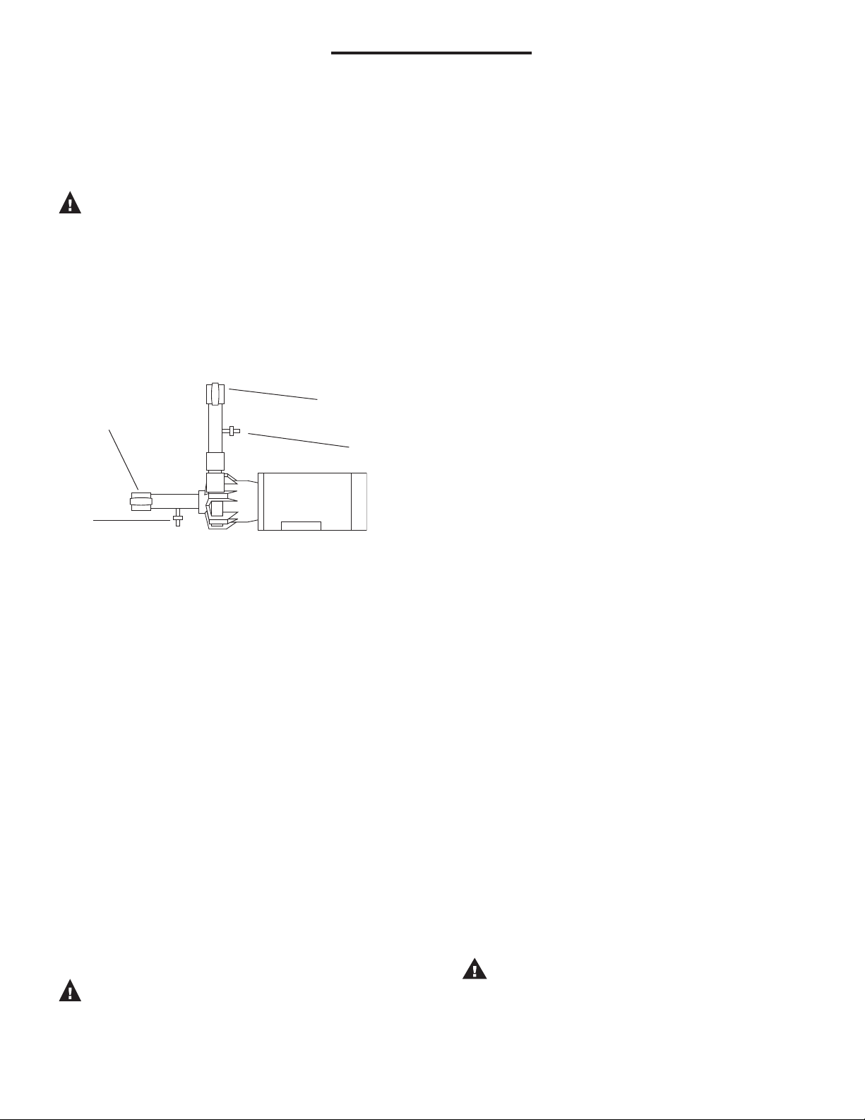
PUMPING LIQUIDS WHICH MAY SOLIDIFY OR CRYSTALLIZE
Add a flush system to the pump’s piping to prevent accumulation of
material inside the pump. Install water inlet and outlet valves as shown
in Figure 1. Refer to the “Operation” section of these instructions for
the flush procedure.
Discharge Valve
Suction Valve
Water Inlet Valve
Figure 1
ELECTRICAL CONNECTIONS
1. Install the motor according to NEC requirements and local electrical
codes. Motor should have an overload protection circuit.
2. Wire the motor for clockwise rotation when facing the fan end of
the motor.
3. To verify correct rotation of the motor:
a. Install the pump into the system.
b. Fully open the suction and discharge valves.
c. Allow fluid to flow into the pump. Do not allow the pump
to run dry.
d. Jog the motor (allow it to run for only one to two seconds)
and observe the rotation of the motor fan. Refer to the
directional arrow on the pump if needed.
NOTE: A pump running backward will run but at a greatly reduced
flow and pressure.
OPERATION
FLOODED SUCTION SYSTEMS
1. Fully open the suction and discharge valves.
2. If a cooling collar is used, turn on the cooling water.
3. Start the pump and verify liquid is flowing. If there is no liquid
flow, refer to the “Troubleshooting” section of these instructions.
4. Adjust the flow rate and pressure by regulating the discharge valve.
CAUTION: Never attempt to adjust the liquid flow with the suction
valve. Limiting the suction will result in damage to the pump's
components.
Water
Outlet Valve
SUCTION LIFT SYSTEMS
1. Fully open suction and discharge valves.
2. If a cooling collar is used, turn on the cooling water.
3. Prime the pump by filling the priming chamber. Allow time for any
trapped air in the suction piping to escape.
4. Start the pump. Adjust the flow rate and pressure by regulating
the discharge valve.
CAUTION: Never attempt to adjust the liquid flow with the suction
valve. Limiting the suction will result in damage to pump components.
FLUSH SYSTEMS
1. Fully close the suction and discharge valves.
2. Connect the water supply to the water inlet valve and connect a
drain hose to water outlet valve.
3. Turn on the water supply and open the inlet and outlet valves. Flush
the system until the pump has been cleared of any material buildup
(approximately 5 minutes).
4. Close the inlet and outlet valves and turn off water supply.
SEALS
SEAL REMOVAL AND INSPECTION
1. Disconnect the piping and electrical power from the pump.
2. Disassemble the pump from the motor adapter.
a. Remove the six hex-head cap screws from the impeller
housing. The impeller housing will loosen if gently tapped at
the discharge outlet.
b. Remove the protective shroud from the motor adapter.
c. While preventing the motor shaft from moving (insert a screw-
driver into the motor’s fan), unscrew the impeller cap with o-ring
and socket head bolt (Items #4,16 and 13) in a counterclockwise
rotation. Use large flathead screw driver and 5/16" hex key.
Remove the impeller, seal, cooling collar (if applicable) and
housing cover as one assembly from the motor shaft.
Note: For pumps using 90, 100/112 motor adapters, leave the
shaft adapter secured to the motor shaft.
3. Remove the seal for inspection.
a. Lubricate the impeller’s shaft with a rubber lubricant emul-
sion or soapy water to allow the seal to slide easier.
Note: Never use a petroleum product for lubrication.
Doing so will effect the seal elastomer’s performance
after reassembly.
b. If no cooling collar is present, carefully remove the retaining
ring that holds the rear of the seal. If equipped with a
cooling collar, carefully slide the cooling collar off of the
impeller’s shaft.
• With single bellows or multi-spring seals, a retain-
ing ring holds the seal in place. Carefully remove
the retaining ring. Loosen the four (4) set screw on
the multi-spring seal.
• With double seals, the cooling collar holds the seal
in place.
CAUTION: The seal’s spring is compressed and under
pressure. Use care when removing.
c. Remove the seal’s spring. Grasp the rotating head of the
seal by hand and twist to remove from the impeller’s shaft.
d. Remove the housing cover from the impeller.
e. Press the ceramic stationary seat portion of the seal out of
the housing cover.
3
Page 4
4. Visually inspect all parts for damage. Replace any parts that appear
worn or damaged.
• Look for scoring of the seal’s ceramic face.
• Inspect the rotating seal face for wear.
• Check for degradation or chemical attack of any
elastomers and other seal components.
• Look for signs of heat damage (melted plastic) to the
housing cover and impeller’s shaft.
SEAL INSTALLATION AND PUMP REASSEMBLY
Single Bellows Seal
1. Install the stationary seal face.
a. Lubricate the stationary face’s o-ring with a rubber lubricant
emulsion or soapy water. Keep the polished surfaces of the
seal face clean.
Note: Never use a petroleum product for lubrication.
Doing so will effect the seal elastomer’s performance
after reassembly.
b. Carefully press the stationary face into the housing cover (use
a piece of cardboard to protect the seal while pressing
against the stationary face). The smoothest side of the station ary face should be facing outward.
2. Install the rotating face.
a. Lubricate the impeller’s shaft with a rubber lubricant emulsion
or soapy water.
b. Carefully slide the housing cover over the impeller’s shaft.
The side of the housing cover with the pressed-in seal face
should be away from the impeller.
c. Separate the rotating head of the seal from the large spring.
Re-lubricate the impeller’s shaft, then carefully slide the rotating
head of the seal over the impeller’s shaft using a twisting
motion. The carbon side of the rotating face should be toward
and pressed against the stationary head of the housing cover.
CAUTION: The carbon portion of the seal is easily
damaged. Take care not to apply uneven force or crack
the carbon while installing.
3. Install the seal’s spring and spring retainer. Compress the spring and
snap the retaining ring (item #8) into the groove on the impeller’s
shaft.
4. Install the assembled seal, impeller and housing cover onto the
motor bracket.
a. If a cooling collar is being used, slide it onto the impeller’s
shaft at this time. Take care to align the water connections
so they are accessible.
b. Install the impeller socket head bolt and cap with o-ring in a
clockwise rotation.
c. Make certain that the housing cover’s o-ring is in place.
d. Place the impeller housing into position and install the hard-
ware. Tighten the six hex-head cap screws to 90 in•lbs.
Multi-Spring Seal
The basic installation procedure for a multi-spring seal is the same as
for the single bellows seal. The exception is that a multi-spring seal has
four (4) set screws which need to be tightened on the impeller shaft.
Double Seal
1. Remove the motor adapter from the motor’s face (it is assumed
that the pump has previously been removed).
2. Install the stationary seal faces.
a. Lubricate the stationary faces’ o-rings with a rubber lubri-
cant emulsion or soapy water. Keep the polished surfaces
of the seal face clean.
Note: Never use a petroleum product for lubrication. Do
ing so will affect the seal elastomer’s performance after
reassembly.
b. Carefully press the stationary faces into the housing cover and
the cooling collar (use a piece of cardboard to protect the seal
while pressing against the stationary face). The smoothest side
of the stationary faces should be facing outward.
Note: If using a special seal material, it is vital that the
special stationary seal face is pressed into the housing cover.
3. Install the rotating faces and cooling collar to the motor adapter.
a. Carefully slide the housing cover over the impeller’s shaft.
The side of the housing cover with the pressed-in seal face
should be away from the impeller.
b. Separate the rotating head of the seal from the spring.
Note: If using a special seal material, it is vital that the
special seal face mates against the housing cover’s sta tionary face.
c. Lubricate the impeller’s shaft, and then carefully slide the
rotating face of the seal over the impeller’s shaft using a
twisting motion. The carbon or special side of the rotating
face should be toward and pressed against the stationary face
of the housing cover.
CAUTION: The carbon or special portion of the seal is
easily damaged. Take care not to apply uneven force or crack
the carbon or special material while installing.
d. Place the seal’s spring into position on top of the installed
rotating face.
e. Re-lubricate the impeller’s shaft and then carefully slide the
second rotating face of the seal over the impeller’s shaft
using a twisting motion (the carbon side of the second
rotating face should be facing away from the other rotating
face). This will require some compression of the seal’s
spring.
f. Place the cooling collar’s o-ring into position. Slide the
cooling collar onto the impeller’s shaft, with the stationary face
in the cooling collar pressed against the second rotating face.
Continue to slide the cooling collar until it mates against the
housing cover. Hold the cooling collar in this position. Take
care to align the water connections so they are accessible.
Notes:
1) The seal’s spring must be compressed further in order to
mate the cooling collar and housing cover.
2) Take care not to pinch the cooling collar’s o-ring. If
the o-ring is not properly seated, the cooling collar will leak.
4. Place the pump components onto the motor adapter. While holding
the cooling collar against the housing cover, install the assembly
into the motor adapter. The motor adapter will hold the cooling
collar in place. It will now be necessary to hold the impeller to
keep the seal’s spring compressed.
5. Carefully place the assembly in position to the motor’s face.
a. In a clockwise rotation, install the impeller socket head bolt and
cap with o-ring. It may be necessary to hold motor’s fan with a
screwdriver to keep the motor shaft from turning.
b. Align the motor adapter so that the access hole is straight up.
c. Install and tighten the impeller’s set screws through the access
hole in the motor adapter (it will be necessary to turn the impeller
to expose the holes in the impeller’s shaft).
4
Page 5

d. Bolt the motor adapter to the motor using the hex-head cap
screws and lock-washers.
e. Double check the alignment of the water connection holes in the
cooling collar.
6. Install the impeller housing.
a. Install the housing cover’s o-ring.
b. Place the impeller housing into position and install the
hardware. Tighten the six hex-head cap screws to 90 in•lbs.
c. Look through the discharge of the pump to verify proper
spacing between the impeller and the housing cover.
TROUBLESHOOTING
NO OR INSUFFICIENT FLOW
1. Pump not primed.
2. Closed valve.
3. Viscosity too high.
4. Air leaks in suction piping.
5. Discharge head higher than anticipated.
6. Suction lift too high or insufficient NPSH. Check also for clogged
suction line.
INSUFFICIENT PRESSURE
1. Air or gasses in liquid.
2. Impeller diameter too small.
3. Discharge head higher than anticipated.
LOSS OF PRIME
1. Leaking suction line.
2. Foot valve or suction opening not submerged enough.
3. Foot valve too small or leaking.
4. Air or gasses in liquid.
5. Foreign matter in impeller.
EXCESSIVE POWER CONSUMPTION
1. Head lower than rating. Excessive flow.
2. Specific gravity or viscosity of liquid is too high.
EXCESSIVE VIBRATION
1. Loose piping or bolts.
2. Pump cavitating from improper suction or feed.
WARRANTY
Finish Thompson, Inc (manufacturer) warrants this pump product to be
free of defects in materials and workmanship for a period of one year
from date of purchase by original purchaser. If a warranted defect, which
is determined by manufacturer’s inspection, occurs within this period, it
will be repaired or replaced at the manufacturer’s option, provided (1) the
product is submitted with proof of purchase
charges are prepaid to the manufacturer. Liability under this warranty is
expressly limited to repairing or replacing the product of parts thereof
date and (2) transportation
and is in lieu of any other warranties, either expressed or implied. This
warranty does apply only to normal wear of the product or components.
This warranty does not apply to products or parts broken due to, in
whole or in part, accident, overload, abuse, chemical attack, tampering,
or alteration. The warranty does not apply to any other equipment used
or purchased in combination with this product. The manufacturer accepts
no responsibility for product damage or personal injuries sustained when
the product is modified in any way. If this warranty does not apply,
the purchaser shall bear all cost for labor, material and transportation.
Manufacturer shall not be liable for incidental or consequential damages
including, but not limited to process down time, transportation costs,
costs associated with replacement or substitution products, labor costs,
product installation or removal costs, or loss of profit. In any and all
events, manufacturer’s liability shall not exceed the purchase price of
the product and/or accessories.
CHEMICAL REACTION DISCLAIMER
The user must exercise primary responsibility in selecting the product’s
materials of construction, which are compatible with the fluid(s) that
come(s) in contact with the product. The user may consult Finish
Thompson, Inc. (manufacturer) and a manufacturer’s representative/
distributor agent to seek a recommendation of the product’s material of
construction that offers the optimum available chemical compatibility.
However neither manufacturer nor agent shall be liable for product
damage or failure, injuries, or any other damage or loss arising out of
a reaction, interaction or any chemical effect that occurs between the
materials of the product’s construction and fluids that come into contact
with the product’s internals.
Call our toll free Technical Service Hot Line, 1-800-888-3743, if you
have any questions regarding product operation or repair.
ORDERING SPARE PARTS
Spare parts can be ordered from your local distributor. Always refer to
pump model number to avoid error.
OTHER FTI PRODUCTS
Drum Transfer Pumps are available in sanitary construction, stainless
steel, polypropylene and CPVC. Flows to 40 gpm, discharge heads to
80 feet and viscosities to 100,000 cP.
Portable Mixers for turbine mixing and blending handle viscosities to
1,000 cP with gentle, non-vortex circulation. Available in 316 stainless
steel construction.
Sealless Mag Drive Centrifugal Pumps in polypropylene and CF PVDF.
Ansi-dimensional mag drives in ETFE lined ductile iron. Flows to 330
gpm and discharge heads to 325 feet. Handle temperatures up to 220°F
(104°C) and have run-dry capability. Mount to standard frame motors.
For further information, contact FTI or your local distributor.
TECH SERVICE 1-800-888-3743
P/N J102611, Rev. 13, 3-26-13
Lit. ID No. FT95-574J
5
 Loading...