

Page 1
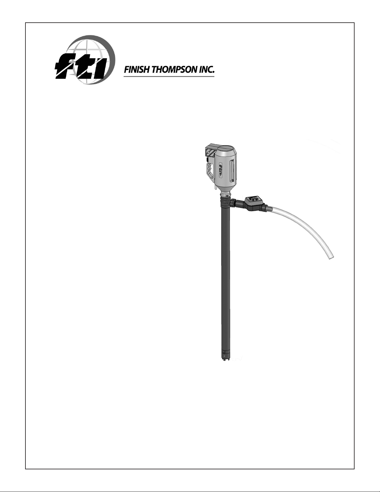
Drum Pump Flow Meter
Model FMBC3000 Series
Operating Instructions
Page 2

Table of Contents
Safety ................................................................................................................................................................ 1
Introduction ........................................................................................................................................................ 1
Specificatons ..................................................................................................................................................... 1
Features ............................................................................................................................................................. 1
Section 1 - Installation ....................................................................................................................................... 2
Section 2 - Operation ......................................................................................................................................... 2
Section 3 - Calibration ........................................................................................................................................ 4
Section 3 - Maintenance .................................................................................................................................... 5
Section 4 - Warranty .......................................................................................................................................... 5
Section 5 - Spare Parts ...................................................................................................................................... 5
Page 3

Safety
ALWAYS wear protective clothing, eye protection, and follow standard safety procedures when handling
corrosive or personally harmful materials.
NEVER use this flow meter with flammable or combustible liquids.
NEVER use this flow meter in a hazardous environment.
ALWAYS verify chemical compatibility with the flow meter and pump materials of construction before operation.
ALWAYS make sure the pump and hose are properly supported.
ALWAYS use a chemically compatible hose rated for the temperature of the product being pumped.
ALWAYS place pump tube in liquid before starting.
Introduction
Thank you for purchasing an FMBC-3000 Series electronic flow meter. The FMBC-3000 Series is designed to measure the flow of a fluid being
dispensed from Finish Thompson’s PFP, PFM, & PFV drum pumps. It also has a batch control feature that automatically stops the pump motor
when a preset, customer adjustable volume has been reached. The meter is factory calibrated and displays information on an LCD display. In
addition, the meter can be field calibrated to improve accuracy at a given flow rate. One lithium battery powers the unit.
FMBC-3000 is a rate/totalizer meter with batch control – designed to measure and display both the rate of flow and the total flow. In addition,
it stops the pump motor when a preset liquid volume has been pumped.
Specifications
Maximum Working Pressure: 35-62 PSIG (2.4 – 4.3 bar)
Maximum Fluid Temperature: PFM & PFP Models = 86º F (30º C)
Ambient Temperature Range: 41º to 122ºF / 5º to 50º C
Enclosure: Splash resistant
Sensor/Paddle/Axle Material: PVDF/PVDF/Hastelloy C
O-ring seals: Viton
Accuracy: +/-1.0% of full-scale rate reading; can be field calibrated
Repeatability: +/-0.5% of full-scale rate reading
Power Requirements: One 3.6V lithium, AA battery included
Battery Life Expectancy: 1 year minimum
Maximum Viscosity: 20 cP/mPas
Maximum Specific Gravity: 1.8
Features
• Easy to read two (6) digit LCD display
• Installs quickly on PFM, PFP, PFV Series pump tubes with supplied fittings
• Batch control feature stops pump motor when preset volume has been pumped
• Displays liters
• Digital flow indicator
• Factory calibrated; can be field calibrated using front panel touch buttons
• Four ranges allow the meter to be calibrated and stored for different fluids or flow rates and can be totaled independently
• Minimal maintenance required
• Corrosion resistant PVDF sensor with polypropylene body
• Splash resistant enclosure
• High accuracy
• Meter automatically turns on and begins operation when flow is detected
• Extended battery life mode – display switches off after 2 minutes without flowLow battery warning
• Non-volatile memory stores settings even when batteries are removed
Kit Contents:
• FMBC-3000 Series Meter with batch control wire
• Batch control relay module
• Flow meter adapter
• Discharge nut
• 1” NPT x 1” BSPP coupling
• 1” BSPP x hose barb adapter
• (2) Viton o-rings
1
Page 4

Section 1 - Installation
NOTE: Avoid exposing the LCD for prolonged periods to direct sunlight or the life of the LCD may be reduced.
1. The meter must be installed so the arrows molded in the body of the meter point away from the pump discharge.
2. Slide two o-rings (Items 3) over threads of flow meter body (item 1) until they reach the face of the body. Wrap Teflon tape on threads of
both ends of flow meter. Screw the Hose Barb Adapter (Item 2) onto discharge end of flow meter. Tighten securely by hand until it com presses the o-ring inside the adapter, being very careful not to over-tighten.
3. Screw coupling (item 4) onto the other end of the flow meter. The coupling is 1” NPT x 1” BSPP. The BSPP end has the larger chamfer.
Make sure the BSPP end is threaded onto the flow meter body. Tighten securely by hand until it compresses the o-ring inside the
coupling, being very careful not to over-tighten.
4. Remove discharge nut, spout and o-ring (items 9, 8, 7) from PF discharge. Discard the discharge nut and spout (or save for later use if no
longer using the pump with a flow meter). Save the o-ring for use in the next step.
5. Place the flow meter adapter (item 6) into the discharge nut (item 5) supplied with the flow meter kit. Threads of the adapter will protrude
through the front of the discharge nut. Place the o-ring
(item 7) inside the discharge nut (item 5). Press down on the o-ring to ensure it is seated in the nut.
6. Screw discharge nut/adapter/o-ring assembly onto the discharge of the PF pump tube. Use a wrench to tighten securely but do not over tighten. This step prevents the adapter from rotating when the flow meter is installed.
7. Grasping the flow meter body (being careful not to put pressure on the digital display), screw the flow meter assembly onto the 1” NPT
discharge adapter on the PF Series pump tube until tight. If the flow meter display is not in the upright position proceed to step 8 for
adjustment.
8. Using a wrench, loosen the discharge nut (item 5) on the discharge of the PF Series tube. Position the flow meter assembly so the display
is in the upright position and retighten the discharge nut (while holding the flow meter assembly).
NOTE: Meter can be tilted as much as 45º from upright position.
WARNING: Use chemicallly compatible hose rated for the temperature of the fluid being pumped.
9. Attach 1” ID hose to the hose barb located at the discharge end of the flow meter. Secure with a hose
clamp.
10. Plug batch control relay module into 230-volt receptacle. Make sure receptacle is within reach of the
batch control wire. See Figure1.
11. Making sure pump motor is in OFF position, plug batch control wire attached to meter into the batch
control relay module.
12. Plug drum pump motor cord into batch control relay module.
Figure 1
Section 2 - Operation
WARNING: When the motor is connected to the batch control relay module, make sure the motor switch is in the OFF position until ready
to use the batch control feature to prevent unintended pump operation.
NOTES:
The FMBC-3000 displays liters.
•
The meter is shipped from the factory with the lithium battery installed.
•
The FMBC-3000 Series is factory calibrated to ± 1% of full-scale rate reading. Accuracy is based
•
on laboratory testing using a PF Series pump tube and water.
The meter automatically turns on and begins operation when flow is detected.
•
Motor can only be turned ON/OFF through the meter when it is connected to the batch control
•
relay module.
Bypass the batch control relay module by plugging the motor into a standard receptacle. The
•
motor can now be operated from the ON/OFF switch on the motor. The motor will now function when the meter is not in batch mode.
Theory of Operation
The meter controls the pump motor. It automatically stops when the customer adjustable, preset volume has been pumped (in batch control
mode) and the meter sends a signal to the batch control relay module. Fluid flowing through the meter causes a radial turbine wheel to spin.
Pulses generated by the spinning turbine wheel are counted and multiplied by scaling factors. Total flow amounts are displayed on the LCD
readout (batch control mode).
2
Page 5

Setting Desired Batch Control Volume
Press the Mode Menu button three times. It will cycle through “Vol”, “Flowrate” and the final menu option is called “Preset” (this is
displayed in the top left of the meter display). The “Preset” menu controls the batch size. When in the “Preset” mode, the bottom right
hand corner displays the batch size.
Using the “+” and “-“ keys adjust the batch size to the desired amount (the amount is shown in the lower right hand corner).
Batch size can be adjusted in increments of .5 liters.
NOTE: Factory default batch size is five liters.
NOTE: The actual volume pumped may exceed the preset batch amount due to the motor continuing to turn the pump shaft for a brief period
after the power is terminated to the motor. The meter WILL display the actual volume pumped. The batch size can be set slightly below the actual
desired batch size to compensate for this overrun.
Operating the Pump/Meter in Batch Mode
The meter must remain in the “Preset” menu for the batch control to be active and functioning. Make sure the pump motor cord and batch control
relay wire are plugged into the batch control relay module. When ready to pump, turn the pump motor switch to the ON position.
Press the Start Stop button to begin pumping. The word “ON” will be displayed in the upper left hand corner. The pump will continue to
pump until the preset batch volume is reached. The pump motor will then automatically stop.
NOTE: The pump motor can be stopped before the batch volume is reached by pressing the Start Stop button. This will terminate this particular
batch and reset the batch total (on the top line of the display) to zero.
NOTE: Whatever range the meter is in (ranges 1-4) will have the accumulated total increased by the amount pumped while in batch mode.
WARNING: Turn the pump motor switch to the OFF position until ready to use the batch control feature again to prevent unintended
pump operation.
Operating the Pump/Meter in Rate and Total Flow Mode
With batch control mode deactivated (pump motor is not plugged into the batch control relay module), pressing the “Mode Menu” button located
on the front panel toggles the display between flow rate and total flow.
Resetting Accumulated Total For each Range
Press and hold the “Set Reset” button and then the “+” button to clear the accumulated total for each range. Each range
must be individually reset.
Changing display from Flowate or Volume
Press the “Mode Menu” button to toggle between the FLOWRATE and VOLUME (displayed as “VOL”) display modes. This
information will be displayed on the top line.
Resetting Volume Setting
With “VOL” displayed on the top line, press the “Set Reset” button to reset the total volume. This is independent of the accumulated total
(displayed in bottom right hand corner).
NOTE: Any time the “Mode Menu” or “+” button is pressed, the volume will be automatically reset to zero.
Additional Features
To access the remaining features, exit the batch mode (“Preset is displayed in the upper left hand corner when in batch mode) by
pressing the “Mode Menu” button. Pressing the button once displays “Vol” mode, twice displays “Flowrate mode”.
While in these two modes (“Vol” and “Flowrate”), pressing the Start Stop button does not allow the pump motor to operate. To operate
the pump motor in these modes plug the pump motor into a standard receptacle.
3
Page 6

Four Flow Ranges
There are four flow ranges. Range 1 is factory set for water. The other three are user adjustable. Each range totals independently from the other
ranges. These ranges can be used to calibrate the meter for different fluids or to accommodate different flow ranges (low, medium and high flow
for example).
Changing From One Range To Another
Press the “+” button to change to another range. Push the button repeatedly until the desired range is reached. The range is displayed in the
Section 3 - Calibration
While the FMBC-3000 has been calibrated at the factory, field calibration is possible to increase accuracy at a given flow. Use the
flowing steps for field calibration.
NOTE: Pump motor MUST NOT be connected to the batch control relay module and MUST be plugged into a standard receptacle.
Step One – Prepare a Calibrated Container
You can either use a known calibrated container or you can create a calibrated container by using a known weight method. In either
case, use as large a container as practical (for instance twenty liter versus one liter container).
To create a calibrated container, weigh the container empty. Fill the container with the desired amount of fluid, mark a line on the
container and reweigh. Subtract the weight of the empty container to get the net fluid weight. Determine the actual volume by
dividing the weight by the specific gravity (density) of the liquid. For example if the fluid is water and the net weight was 20 kg, the
container has 20 liters of liquid (20 divided by 1 kg per liter which is the weight of water per liter).
Step Two – Enter Calibration Mode
To enter the calibration mode, press and hold the “Mode Menu” button and then the “+” button. “CAL” will be displayed on
the top of the screen when this mode is active.
NOTE: The meter must be in Range 2,3 or 4 to calibrate the meter. Range 1 is factory calibrated for water-like fluids and cannot
be changed.
Step Three – Measure Actual Volume
Turn on the pump motor and fill the container container to the fill mark on the container from Step One. Compare the actual volume of the fluid
being pumped (determined by Step One) with the volume shown on the meter.
Step Four – Enter Actual Volume into Meter
Make sure the pump motor is “OFF” and no flow is passing through the meter. Using the “+” or “-“ buttons, adjust the volume on
the flow meter display (top line) to match the actual volume pumped. Press the “Set Reset” button to store this data. The
new calibration factor will briefly flash in lower right hand corner.
NOTE: If no reading is entered within two minutes, the meter will automatically shutoff and exit the calibration mode.
NOTE: All four ranges are preset with a calibration factor of 182.0
NOTE: If “Set Reset” button is pressed before any liquid passes through the meter when it is in calibration mode, an incorrect calibration factor
will result. If this occurs, “EE” will briefly flash on the bottom line of the display. If this occurs, the meter will need to be calibrated again.
NOTE: To verify that the meter is properly calibrated, repeat Step three. If not, repeat calibration process.
Restoring Factory Defaults
To restore all the meter settings to the factory defaults, enter the programming menu by pressing and holding the “Mode
Menu” button and then press and hold the “+” button, then press and hold the “-” buttons at the same time. Then press
the “Set Reset” button to restore factory defaults and automatically exit the programming mode.
NOTE: This will return all four calibration ranges to factory settings. It also resets accumulated totals for all four ranges and restores default batch preset value (amount) to 5.0 liters.
Flow Indicator
The top center of the meter display has a flow direction indicator. The legs will turn in a clockwise direction when the flow direction is
correct. If the flow is backwards through the meter, the legs do not turn and the flow total is subtracted by the amount flowing through the
meter backwards.
4
Page 7

Section 4 - Maintenance
The FMBC-3000 Series was engineered for low maintenance; however, some conditions will cause increased wear on the paddle and/or possible
damage to the unit. Damage caused by corrosives incompatible with the meters materials of construction or abrasive fluids is not covered under
warranty.
• Replace the battery when the low battery indicator (“Batt”) is displayed in the lower right hand corner. Make sure the meter is in “Power Save”
mode (meter is off with nothing displayed on the front panel) before replacing the battery. The program memory is “non-volatile” and will not
erase when replacing the battery. To replace the battery, open the meter enclosure by removing the four Phillips screws from the back of the
meter. The battery is a lithium 3.6 volt, “AA” size. After replacing the battery, be sure the o-ring seal is in place and is in good condition, before
reinstalling the screws.
Section 5 - Warranty
Finish Thompson, Inc (manufacturer) warrants this product to be free of defects in materials and workmanship for a period of one year from date
of purchase by original purchaser. If a warranted defect, which is determined by manufacturer’s inspection, occurs within this period, it will be
repaired or replaced at the manufacturer’s option, provided (1) the product is submitted with proof of purchase date and (2) transportation charges
are prepaid to the manufacturer. Liability under this warranty is expressly limited to repairing or replacing the product or parts thereof and is in
lieu of any other warranties, either expressed or implied. This warranty does apply only to normal wear of the product or components. This warranty does not apply to products or parts broken due to, in whole or in part, accident, overload, abuse, chemical attack, tampering, or alteration.
The manufacturer accepts no responsibility for product damage or personal injuries sustained when the product is modified in any way. If this
warranty does not apply, the purchaser shall bear all cost for labor, material and transportation.
Manufacturer shall not be liable for incidental or consequential damages including, but not limited to process down time, transportation costs,
costs associated with replacement or substitution products, labor costs, product installation or removal costs, or loss of profit. In any and all
events, manufacturer’s liability shall not exceed the purchase price of the product and/or accessories.
Section 6 - Parts List
Item
Number
3, 7 1 O-ring, Viton J100991
Quantity Description Part
2 1 1” BSPP x hose barb adapter, polypropylene 106737
4 1 1” NPT x 1” BSPP coupling, polypropylene 106736
5 1 Discharge nut, polypropylene 106622
6 1 Flow meter adapter, polypropylene 106599
1 Batch Control Relay 106739
Number
Literature ID Number FT08-1016
Part Number 106784
 Loading...