

Page 1
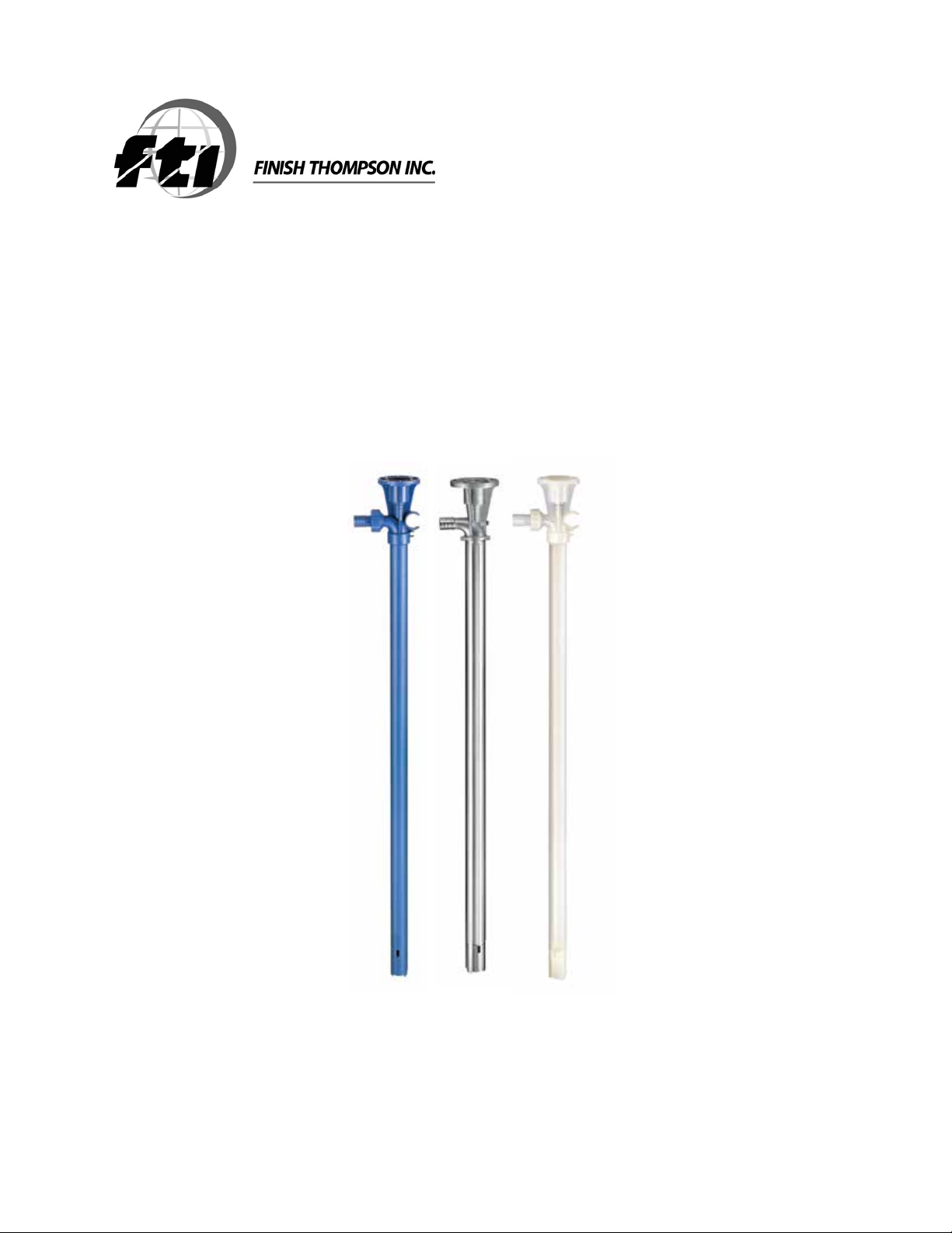
EF SERIES PUMPS
EFP, EFS, & EFV
OPERATION & PARTS MANUAL
Page 2

EU Declaration of Conformity
Finish Thompson Inc. hereby declares that the following machine(s) fully comply with the
applicable health and safety requirements as specified be the EC Directives listed.
The product may not be taken into service until it has been established that the drive motor
for the Drum and Container Pump complies with the provisions of all relevant EC Directives.
The complete product complies with the provisions of the EC Directive on machinery safety
provided motors manufactured by Finish Thompson Inc. are used.
This declaration is valid provided that the devices are fully assembled and no modifications
are made to these devices.
BTS – 40 EPPI/EPPS 15/27/40 EFP/EFV/EFS-16/27/40/48
HVDP LR-27/40/48 HVDP HR-27/40/28 PFM-27/40/48/60
PFP-15/27/40/48/60/72 PFS-27/40/48/60/72 PFV-27/40/48/60/72
TBP-27/40/48 TBS-40 TTC/TTS-27/40/48
STTS-40 TMS-40
Type of Device:
Drum and Container Pump Tubes
Models:
EC Directives:
Machinery Safety (2006/42/EC)
Applied Harmonized Standards:
EN ISO 12100 Part 1
EN ISO 12100 Part 2
EN 809
Manufacturer:
Finish Thompson Inc.
921 Greengarden Road
Erie, Pennsylvania 16501-1591 U.S.A
Signed,
_
President
January 7, 2013
Person(s) Authorized to Compile Technical File: Michael Smith Engineers Limited
Oaks Road, Woking, Surrey
GU21 6PH, UK
Telephone: 01483 771871
Page 3

Introduction
This manual pertains to the EF Series drum pumps. Finish Thompson Inc. thanks you for choosing our products. We
believe the use of our products will be fully satisfactory. When properly installed and operated, your Finish Thompson
motor and pump will provide long, trouble-free service; therefore, please read this manual carefully before carrying
out any operations on the pump/motor unit. Any use other than that described herein is considered incorrect; and,
consequently, Finish Thompson Inc. shall not be held responsible for any damages to people or property. In case of
doubt or enquiries, please reply to our Technical Service department directly at the following address:
Finish Thompson, Inc.
921 Greengarden Rd.
Erie, PA 16501 U.S.A.
Tel. 1-814-455-4478; Fax 1-814-455-8518
www.finishthompson.com; fti@finishthompson.com
Index
Introduction/ Pump Specifications ................................................................................1
Warranty, General Terms & Conditions ..........................................................................2
Safety ...........................................................................................................................3
Specifications & Dimensions ........................................................................................4
Disassembly .................................................................................................................5-6
Reassembly ..................................................................................................................6-7
Exploded Views – EFP/EFV/EFS Pump Tubes .................................................................8-9
Pump Tube Spare Parts List ..........................................................................................10-11
Note: Repair instructions can be downloaded from our web site at www.finishthompson.com or contact
Technical Service at 1-800-888-3743.
1
Page 4

Warranty, General Terms & Conditions
1. The following terms and conditions apply to the sale of machinery, components and related services and products, of Finish
Thompson Inc. (hereinafter “the products”)
2. Finish Thompson Inc. (the manufacturer) warrants only that:
a) its products are free of defects in material, design and workmanship at the time of original purchase;
b) its products will function in accordance with Finish Thompson Inc. operation manuals; Finish Thompson Inc. does not
guarantee that the product will meet the precise needs of the Customer, except for those purposes set out in any invitation
to render documents or other documents specifically made available to Finish Thompson Inc. before entering into this
agreement;
c) high quality materials are used in the construction of the pumps and that machining and assembly are carried out to the
highest standards. Except as expressly stated above, Finish Thompson Inc. makes no warranties, express or implied,
concerning the products, including all warranties of fitness for a particular purpose.
This warranty shall not be applicable in circumstances other than defects in material, design, and workmanship. In particular
warranty shall not cover the following:
d) Periodic checks, maintenance, repair and replacement of parts due to normal wear and tear;
e) Damage to the product resulting from:
i. Tampering with, abuse or misuse, including but not limited to failure to use the product for its normal purposes as
stated at the time of purchase or in accordance with Finish Thompson, Inc. instructions for use and maintenance of the
product, or the installation or improper ventilation or use of the product in a manner inconsistent with the technical or
safety standard in force;
ii. Repairs performed by non-authorized service workshop, or opening of the unit by non-authorized personnel, or use of
non genuine Finish Thompson Inc. parts;
iii. Accidents, force majeure or any cause beyond the control of Finish Thompson Inc., including but not limited to light ning, water, fire, earthquake, and public disturbances, etc.
3. The warranty shall cover the replacement or repair of any part, which is documented to be faulty due to construction or as sembling, with new or repaired parts free of charge delivered by Finish Thompson, Inc. Parts subjected to normal wear and
tear shall not be covered by the warranty. Finish Thompson, Inc. shall decide as to whether the defective or faulty part shall be
replaced or repaired. Transportation charges are prepaid to Finish Thompson.
4. The warranty of the products shall be valid for a period of 12 months from the date of delivery, under the condition that notice
of the alleged defect to the products or parts thereof be given to Finish Thompson, Inc. within the term of 8 days from the
discovery.
5. Repair or replacement under the terms of this warranty shall not give a right to an extension to, or a new commencement of,
the period of warranty. Repair or replacement under the terms of this warranty may be fulfilled with functionally equivalent re conditioned units. Finish Thompson Inc. qualified personnel shall be solely entitled to carry out repair or replacement of faulty
parts after careful examination of the motor. Faulty parts or components when replaced by Finish Thompson Inc. will become
the property of Finish Thompson Inc. If this warranty does not apply, the purchaser shall bear all cost for labor, material and
transportation.
6. Finish Thompson Inc. will not be liable on any claim, whether in contact, tort, or otherwise, for any indirect, special, incidental,
or consequential damages, caused to the customer or to third parties, including loss of profits, process down time, transpor tation costs, costs associated with replacement or substitution products, labor costs, installation or removal costs. In any and
all events, manufacturer’s liability shall not exceed the purchase price of the product and/or accessories.
7. Return Policy. Should you have any problems with this product, please contact the distributor in your area. The distributor
will determine if a return to the factory is necessary and will contact the factory for a Return Authorization Number. Otherwise,
contact our Technical Service Hotline (1-800-888-3743) or e-mail techservice@finishthompson.com if you have any questions
regarding product operation or repair.
2
Page 5

Safety
1. Introduction
This manual contains all the information needed for the correct installation, use and maintenance of your new Finish Thompson
pump. It should be read and understood by all the personnel involved in installation, operating and servicing of the pump before
it is started.
2. Operator Qualification and Training
The personnel in charge of the installation, the operation, and the maintenance of the pump must be qualified and able to per form the operations described in this manual. Finish Thompson, Inc. shall not be held responsible for the training level of
personnel and for the fact that they are not fully aware of the contents of this manual.
3. Safety Instructions
FOR YOUR OWN SAFETY
BEFORE using or servicing your pump, please make sure to wear the proper clothing, eye protection and follow standard safety
procedures when handling corrosive or personally harmful materials.
GENERAL DANGER
NEVER use a plastic pump or an open, splash-proof, TEFC or non-ATEX motor when pumping or mixing flammable or combus tible material.
ALWAYS use a Model EFS 316SS pump tube with Model S4 air motor and static protection kit with grounded discharge hose,
P/N 107429, when pumping or mixing flammable or combustible material. Follow Assembly, Installation & Operating Instructions
from manual, P/N J102721, included with the static protection kit or it can be accessed online at www.finishthompson.com/
downloads.
ALWAYS use and store the pump and motor in an upright position.
DANGER: POWER SUPPLY
Refer to instructions in the appropriate motor Operation & Installation Manual.
4. Noise Level
Refer to specifications in the appropriate motor Operation & Installation Manual.
5. Modifications and Spare Parts
Any changes concerning the service of the pump as originally purchased can be executed only after written approval from
Finish Thompson Inc. It is recommended to use only genuine Finish Thompson Inc. spare parts and approved accessories. The
use of non-original spare parts or non-approved accessories will void warranty and removes any responsibility on the manufac turer’s behalf for any damage caused to people or things.
6. Cleaning
It is highly recommended to flush pumps with clean water or some other neutralizing fluid compatible with pump materials
when done pumping or when switching chemicals.
Hose & Cord Storage
EFP & EFV model pumps have a built-in hose & cord clip. You can use these clips to store your hose and keep the plug off the floor,
free of damage and corrosion. When selecting a discharge hose, you should use a 3/4" ID reinforced chemically compatible hose
secured with a stainless steel hose clamp. See figures A and B below.
Figure BFigure A
3
Page 6

PUMP SPECIFICATIONS
Outer Tube Diameter 1-1/4” (3.22 cm) 1-5/16” (3.3 cm) 1-1/4” (3.2 cm)
Discharge Spout 3/4” Barb 3/4” Barb 3/4” Barb
Discharge Thread 1” NPT 1” NPT Optional
Max. Specific Gravity 1.6 1.6 1.6
Max. Viscosity 300 cP 300 cP 300 cP
Min./ Max. Fluid Temperature
Wetted Materials
*EFV-54 Maximum Temperature = 150° F (66° C)
Polypropylene, FKM, PTFE, ETFE,
MODEL EFP MODEL EFV MODEL EFS
0° F Min. to 150° F Max. 0° F Min. to 160° F* Max. 0° F Min. to 212° F Max.
(-18° C Min. to 66° C Max.) (-18° C Min. to 71° C* Max.) (-18° C Min. to 100° C Max.)
316 SS
Pure Polypropylene, PVDF, FKM,
PTFE, ETFE, Alloy 625
316 SS, FKM, PTFE, ETFE
4
Page 7

DISASSEMBLY & REASSEMBLY INSTRUCTIONS
Disassembly
1. Prior to disassembly - remove the motor and discharge tubing.
2. Diffuser Removal - For EFP & EFV Models – When looking at the bottom of the
pump, loosen the diffuser (item 17) by turning it clockwise (left-hand thread) 2-3 turns
or until it touches the impeller (item 18). See figure 1.
3. Impeller Removal - Using a flat-head screwdriver, unthread the impeller (item 18)
by turning it counter clockwise (right-hand thread). Hold the coupling insert and
coupling (items 1 & 2) in one hand, and unthread with the other. Note: If the shaft
unthreads from the coupling, use a pliers to hold the top of the shaft. Care should be
taken to not damage the shaft threads. For longer 40” and 48” pump lengths, two
people may be required to hold the shaft and unthread the impeller. See figure 2.
4. Unthread the impeller roughly 10 turns or until loose.
Figure 1
5. Now finish unthreading the diffuser. If the impeller is loose, it will come off with the diffuser.
Figure 2
6. To remove the impeller from the diffuser, shake it until it engages the impeller guard inside the diffuser, and turn it
counter clockwise with a flat head screwdriver or your fingers.
7. Diffuser Removal - For EFS Models - Unthread the diffuser cover (item 19). Turn it clockwise (left-hand thread).
Unthread the impeller (item 18) turning it counter clockwise (right hand thread) using a flat-head screwdriver or hand
while holding the coupling insert and coupling (items 1 & 2) with the other hand. Note: If the shaft unthreads from the
coupling, use a pliers to hold the top of the shaft. Care should be taken to not damage the shaft threads. For longer
40” and 48” pump lengths, two people may be required to hold the shaft and unthread the impeller. Unthread the diffuser (item 17) turning it clockwise (left-hand thread).
8. Shaft Removal - for all models - To remove the shaft (item 4), tap the bottom of the shaft on a piece of wood or plas-
tic and push the shaft up and out of the head (item 6). Grab the half coupling or bearing and pull the shaft assembly
straight out of the head. Note: Take care to not bend the shaft. Important - The shaft should only be removed if the
bearing is frozen and needs to be replaced.
9. Outer Tube Removal - For EFP & EFV Models - Remove the outer tube (item 16). Hold the head (item 6) in one hand
and with the other hand, turn the outer tube clockwise (left-hand thread). When completely unthreaded, pull the outer
tube away from the head exposing the inner tube and center support (items 13 & 14).
10. Inner Tube & Center Support Removal - To remove the inner tube and center sup-
port, turn the inner tube to unseat the o-rings (item 12) and then pull the inner tube
away from the head.
11. Shaft Sleeve Removal - The shaft sleeve (item 15) will drop out of the inner tube by
holding it in a vertical position and turning.
12. Center Support Removal - 40” and 48” lengths only - If the center support (item 14)
needs to be replaced, it can be removed by spreading open the fingers and disengaging it from the inner tube. See figure 3.
5
Figure 3
Page 8

13. Inner Tube & Shaft Sleeve Removal - The outer tube and head for EFS models are
welded together. To remove the inner tube and shaft sleeve (items 13 & 15 indicated
on the Exploded View on pg. 8-9), hold the outer tube and head assembly in a vertical position, and the shaft sleeve will fall out. To remove the inner tube, “pretend” to
hit the bottom of the pump on the floor but stop before it actually hits. This motion
will allow the weight of the inner tube to release the o-rings, and it will drop out of
the bottom of the pump. It is recommended to do this over a soft surface to prevent
damaging the inner tube as it drops out of the pump.
14. Seal Removal - To remove the seal (item 5) from the head (item 6 or item 16 for EFS),
use a hook tool, available at most hardware stores, to pull the seal out from the top of
the head. Take care not to damage the seal seat area. See figure 4. Note: The seal
should be replaced if worn or the bearing is failing or frozen.
Figure 4
Reassembly
1. Seal Installation for EFP & EFV models - Take the head (item 6), and for EFS models take the outer tube with head
(item 16), and install a new seal (item 5). Insert the open part of the seal into the lower bore of the head. See figure 5.
Use a 3/8” (9.5 mm) dowel to press and seat the seal into place. Seal sits slightly below the surface. See figure 6.
Figure 5
Figure 6
2. Reinstall the half coupling, bearing and shaft (items 2, 3 & 4 indicated on the Exploded View on pg. 8-9) as an
assembly into the head. If the bearing needs to be replaced it is recommended to purchase a new shaft, bearing and
half coupling assembly because the EF Series shaft can be damaged when removing or installing the bearing.
3. Shaft Installation - Slide the shaft down through the seal until the bearing
engages the bearing bore in the head. Use any size dowel under 1”(25.4 mm) in
diameter and press the half coupling, bearing and shaft into place using an arbor
press or by lightly tapping with a soft mallet. Note: Do not use excessive force.
Unthread the half coupling counter clockwise (right hand thread) to verify that the
bearing is seated properly. See figure 7. Reinstall the half coupling.
4. Inner Tube, Center Support & Shaft Sleeve Installation - for all models -
Reinstall the inner tube, center support (if used) and shaft sleeve (items 13, 14 &
Figure 7
15). Slide the shaft sleeve onto the shaft. The shaft sleeve is self-positioning so
slide it up as far as it will go on the shaft. Reinstall the inner tube with center support (if used) over the shaft and
shaft sleeve. The double o-ring side seats up into the head with a slight twisting motion. Make sure the inner tube
is seated properly. The bottom of the inner tube will be flush with the bottom of the outer tube when properly seated.
6
Page 9

5. Outer Tube Installation - for EFP & EFV models - Install the outer tube
(item 16). Make sure the center support (if used) is installed correctly on
the inner tube. The center support has a slight taper that allows the outer
tube to slide easily over it.
See figure 8. Slide the outer tube with external threads over the shaft,
shaft sleeve, inner tube and center support (if used) up into the head (item
6). Turn the outer tube counter clockwise (left hand thread) to tighten it into
the head. Hand tighten.
Figure 8
6. Diffuser Installation - for all models - Install the diffuser (item 17) onto the
bottom of the outer tube. Insert the shaft through the small support opening
on the diffuser. See figure 9. The small support opening will insert up inside
the inner tube (item 13). With a slight push and turn, thread the diffuser into
the outer tube (item 16) turning counter clockwise (left hand thread). EFP
and EFV models - only tighten the diffuser halfway or 3-4 turns. See figure
10. Insert the impeller (item 18) into the bottom of the diffuser. With a slight
push and turn the impeller should twist through the impeller guards and en gage the shaft threads. Use a flathead screwdriver to tighten the impeller to
the shaft turning clockwise (right hand thread). See figure 11. Hold the half
coupling (item 2) in one hand while turning the impeller with the other.
Figure 9
Hand tighten. Once the impeller is tightened, finish tightening the diffuser turning counter clockwise (left hand thread).
Hand tighten.
Figure 10
Figure 11
7. For EFS Models - Thread the diffuser (item 17) completely onto the bottom of the outer tube (item 16). Thread the
impeller onto the shaft by hand. While holding the half coupling with the other hand, turn the impeller clockwise
(right hand thread). See figure 12. Install the diffuser cover (item 19), EFS models only, onto the diffuser turning
counter clockwise (left hand thread). Hand Tighten.
Figure 12
7
Page 10

EFP & EFV SERIES PUMP
EXPLODED VIEW
8
Page 11

EFS SERIES PUMP
EXPLODED VIEW
9
Page 12

PUMP SPARE PARTS LIST
ITEM QTY DESCRIPTION
*1 1
2 1
3 1
4 1
*2,3,4 1
*5 1
6 1
7 4
8 4
*9 1
10 1
11 1
*12 2
13 1
*14 1
*15 1
16 1
*17 1
COUPLING INSERT
COUPLING HALF
BEARING
AVAILABLE ONLY AS PART OF COUPLING HALF, BEARING & SHAFT ASSEMBLY
SHAFT
AVAILABLE ONLY AS PART OF COUPLING HALF, BEARING & SHAFT ASSEMBLY
COUPLING HALF, BEARING & SHAFT ASSEMBLY
COUPLING HALF, BEARING & SHAFT - 16” 107589-1 107590-1 107589-1
COUPLING HALF, BEARING & SHAFT - 27” 107589-2 107590-2 107589-2
COUPLING HALF, BEARING & SHAFT - 40” 107589-3 107590-3 107589-3
COUPLING HALF, BEARING & SHAFT - 48” 107589-4 107590-4 107589-4
COUPLING HALF, BEARING & SHAFT - 54” 107589-5 107590-5 N/A
SEAL
FKM 107297 107297 107297
PUMP HEAD
POLYPROPYLENE 107071-1 N/A N/A
PVDF N/A 107071-2 N/A
FLAT WASHER
STAINLESS STEEL J103601 J103601 N/A
HI-LOW SCREW
STAINLESS STEEL J101020 J101020 J101020
SPOUT O-RING
FKM (STANDARD) 106155 106155 N/A
EPDM 106154 106154 N/A
SPOUT
POLYPROPYLENE 107072-1 N/A N/A
PVDF N/A 107072-2 N/A
NUT
POLYPROPYLENE 107069-1 N/A N/A
PVDF N/A 107069-2 N/A
INNER TUBE O-RING
FKM (STANDARD) 107299 107299 107299
EPDM 107729 107729 107729
INNER TUBE
16” 107294-1 107294-1 107578-1
27” 107294-2 107294-2 107578-2
40” 107294-3 107294-3 107578-3
48” 107294-4 107294-4 107578-4
54” 107294-5 107294-5 N/A
CENTER SUPPORT
TEFZEL
SHAFT SLEEVE - PTFE
16” 107293-1 107293-1 107293-1
27” 107293-2 107293-2 107293-2
40” 107293-3 107293-3 107293-3
48” 107293-4 107293-4 107293-4
54” 107293-5 107293-5 N/A
OUTER TUBE (MODEL EFS INCLUDES PUMP HEAD)
16” 107295-1 107295-2 107580-1
27” 107295-3 107295-4 107580-2
40” 107295-5 107295-6 107580-3
48” 107295-7 107295-8 107580-4
54” 107295-9 107295-10 N/A
DIFFUSER
POLYPROPYLENE 107070-1 N/A N/A
PVDF N/A 107070-2 N/A
316 STAINLESS STEEL (W/ PTFE BUSHING) N/A N/A 108115
®
(ETFE) - 40” & 48” LENGTHS ONLY 107068 107068 N/A
PART NUMBER
MODEL EFP MODEL EFV MODEL EFS
J103422 J103422 J103422
107300 107300 107300
N/A = Not Applicable
10
Page 13

ITEM QTY DESCRIPTION
IMPELLER
*18 1
19 1
20 1
*21 1
22 1
23 1
POLYPROPYLENE 107067-1 N/A N/A
TEFZEL
DIFFUSER COVER
316 STAINLESS STEEL N/A N/A 107584
DIFFUSER BUSHING
PTFE N/A N/A 107585
DIFFUSER O-RING
FKM (STANDARD) N/A N/A 107586
EPDM N/A N/A 107766
GROUNDING SCREW
BRASS N/A N/A J100822
GROUNDING SCREW LOCKWASHER
BRASS N/A N/A J100823
®
(ETFE) N/A 107067-2 107067-2
MODEL EFP MODEL EFV MODEL EFS
PART NUMBER
N/A = Not Applicable
* Recommended Spare Parts
®
Tefzel
is a registered trademark of the DuPont Company.
Service 1-800-888-3743
P/N 107317, Rev8, 3-5-13
 Loading...