

Page 1
DB22 SERIES
ASSEMBLY, INSTALLATION AND
OPERATION MANUAL
Literature ID No. FT08-1023H
Page 2
2
Page 3

TABLE OF CONTENTS
Description Page Number
Model Number/Serial Number ............................................................................................. 4
Important Notice ................................................................................................................. 4
Chemical Reaction Disclaimer ............................................................................................. 4
Safety Precautions ............................................................................................................. 4
Temperature Classification .................................................................................................. 5
DB22 Capabilities
Maximum Working Pressure ........................................................................................... 6
Maximum Temperature................................................................................................... 6
Solids ............................................................................................................................. 6
Minimum Flow Rate .......................................................................................................6
Maximum Motor Power ..................................................................................................6
Maximum Specific Gravity .............................................................................................. 6
Section I - Assembly ............................................................................................................7
Section II - Installation ......................................................................................................... 8
Section III - Start-up and Operation
Start-up ......................................................................................................................... 9
Shutdown ....................................................................................................................... 9
Flush Systems ................................................................................................................ 9
Optional Drain installation ...............................................................................................9
Section IV - Maintenance
Disassembly ................................................................................................................... 9
Outer Drive Replacement ................................................................................................10
Thrust Ring Replacement ...............................................................................................10
Bushing Replacement .....................................................................................................11
Impeller Replacement .....................................................................................................11
Reassembly.................................................................................................................... 11
DB22 Part Number Explanation ......................................................................................12
DB22 Exploded View Parts Diagram ................................................................................ 13
Spare Parts List ............................................................................................................ 14-17
Troubleshooting .............................................................................................................. 18
Section V - Warranty ............................................................................................................ 18
Note: Maintenance videos are now available on line at www.finishthompson.com.
For factory assistance with repairs or maintenance, call 1-800-888-3743.
3
Page 4

Model Number and Serial Number
Record the model number and serial number below for future reference. This is important information when ordering replacement
parts or when technical assistance is required. The numbers are found on a label located on the motor adapter.
MODEL NUMBER ___________________________
SERIAL NUMBER __________________________
IMPORTANT NOTICE
U.S. Export Administration Regulations, pursuant to ECCN 2B350, prohibit the export or reexport to certain enumerated countries of
sealless centrifugal pumps in which all wetted materials are constructed from fluoropolymers without first applying for and obtaining
a license from the U.S. Bureau of Industry and Security (BIS). This affects all Finish Thompson magnetic-drive pumps constructed from
PVDF or lined with ETFE. Please contact the BIS (www.bis.doc.gov) or Finish Thompson with questions regarding the Regulations or a
list of the countries to which they apply.
Chemical Reaction Disclaimer
The user must exercise primary responsibility in selecting the product’s materials of construction, which are compatible with the
fluid(s) that come(s) in contact with the product. The user may consult Finish Thompson, Inc. (manufacturer) and a manufacturer’s
representative/distributor agent to seek a recommendation of the product’s material of construction that offers the optimum available chemical compatibility.
However neither manufacturer nor agent shall be liable for product damage or failure, injuries, or any other damage or loss arising
out of a reaction, interaction or any chemical effect that occurs between the materials of the product’s construction and fluids that
come into contact with the product’s components.
Safety Precautions
WARNING: READ THIS MANUAL COMPLETELY BEFORE INSTALLING AND OPERATING THIS UNIT. FAILURE TO FOLLOW THESE
PRECAUTIONS CAN RESULT IN SERIOUS INJURY OR DEATH.
WARNING: Magnetic field hazard. This pump contains powerful magnets. Exposed magnets (pump not connected to motor)
produce powerful magnetic fields. Individuals with cardiac pacemakers, implanted defibrillators, other electronic medical devices,
metallic prosthetic heart valves, internal wound clips (from surgery), metallic prosthetic devices or sickle cell anemia must not
handle or be in the proximity of the magnets contained inside the pump. Consult a health care provider for specific recommendations before working with this pump.
WARNING: Magnetic force hazard. This pump should only be disassembled and assembled using the recommended procedures.
The magnetic attraction is powerful enough to rapidly pull the motor end and the wet end together. Do not place fingers between the
mating surfaces of the motor and wet ends to avoid injuries. Keep the drive magnet and impeller assembly away from metal chips or
particles, items with magnetic stripes like credit cards and magnetic computer media such as floppy discs and hard drives.
WARNING: Guidelines for pumping flammable or combustible liquids. Follow these guidelines when pumping flammable
or combustible liquids with a DB Series pump:
1. You must use a PVDF pump. PVDF has conductive carbon fibers added which allow it to be grounded when installed in a prop erly grounded piping system or when a properly installed grounding strap is attached to a housing bolt. If PVDF is not compatible
with the liquid, you should then consider an ETFE lined UC Series mag-drive pump.
2. You must select the non-sparking (Ns) bronze bump ring option. The non-sparking ring is pressed into the clamp ring or motor
adapter and prevents sparking should the motor bearingsfail and the outer mag drive assembly runs out of round.
3. Select and FTI explosion-proof motor or provide your own explosion-proof motor.
Follow these guidelines when pumping non-flammable or non-combustible liquids in a hazardous area with a DB Series
pump:
1. You must select the non- sparking (Ns) bronze bump ring option. The non-sparking ring is pressed into the clamp ring or motor
adapter and prevents sparking should the motor bearingsfail and the outer mag drive assembly runs out of round.
2. Select and FTI explosion-proof motor or provide your own explosion-proof motor.
4
Page 5
WARNING: Hot surfaces. This pump is capable of handling liquids with temperatures as high as 220º F (104º C). This may
cause the outer areas of the pump to become hot as well and could cause burns.
WARNING: Rotating Parts. This pump has components that rotate while in operation. Follow local safety standards for locking
out the motor from the power supply during maintenance or service.
WARNING: Chemical Hazard. This pump is used for transferring many types of potentially dangerous chemicals. Always wear
protective clothing, eye protection and follow standard safety procedures when handling corrosive or personally harmful materials.
Proper procedures should be followed for draining and decontaminating the pump before disassembly and inspection of the pump.
There may be small quantities of chemicals present during inspection.
WARNING: Never run pump at less than minimum flow or with the discharge valve closed. This could lead to pump failure.
WARNING: The pump and associated components are heavy. Failure to properly support the pump during lifting and movement
could result in serious injury or damage to the pump and components.
CAUTION: This pump should never be started without liquid in the casing. If the pump has a PTFE, ceramic or silicon carbide
bushing, IT CANNOT BE RUN DRY WITHOUT CAUSING DAMAGE TO THE PUMP. It is recommended that run dry protection be used.
Optional electronic power monitors are available to help protect against run dry. However, the pump can operate without liquid in
the housing if the pump has a carbon bushing. The exact length of time the pump can operate dry with a carbon bushing varies with
operating conditions and environment.
CAUTION: Never start or operate with a closed suction valve.
WARNING: Operation without priming or against a closed discharge valve can result in high temperatures that can result in
injury or damage to pump components.
CAUTION: Always provide adequate NPSHa (net positive suction head available). It is recommended to provide at least 2 feet (61
cm) above the NPSHr (net positive suction head required).
CAUTION: If pump is used on variable speed drive, do not exceed the frequency for which the pump was designed (for example, if the pump is a 50 Hz model, do not exceed 50 Hz).
Safety Precautions for ATEX Pumps
CAUTION: Proper o-ring material must be chosen for the fluid being pumped. Improper material selection could lead to swelling
and be a possible source of leaks. This is the responsibility of the end user.
WARNING: The pump must be checked for leaks on a regular basis. If leaks are noticed, the pump must be repaired or replaced
immediately.
WARNING: The pump must be cleaned on a regular basis to avoid dust buildup greater than 5 mm.
WARNING: ATEX pumps must use a power monitor, flow switch, pressure switch or similar device to help protect against run-
ning dry, closed discharge valve and decoupling. Any of these conditions could lead to a rise in surface temperature of the pump.
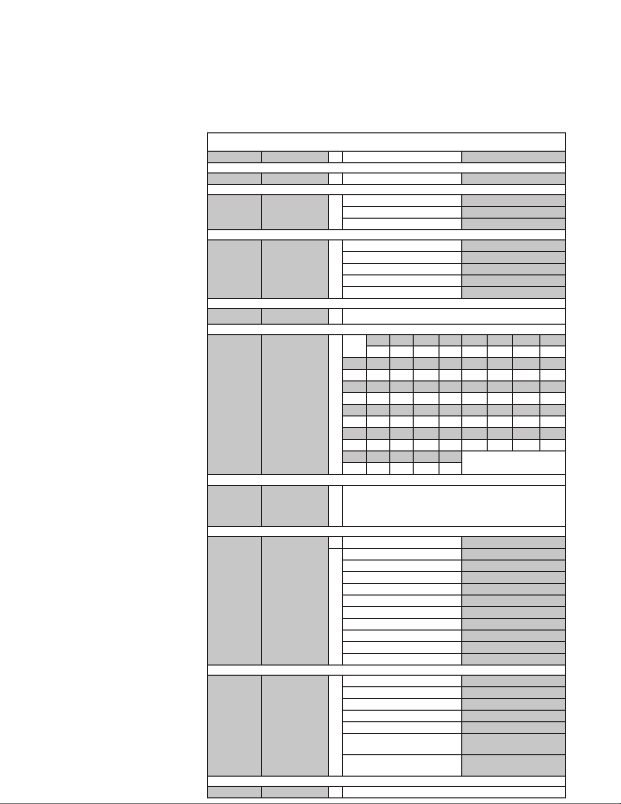
Temperature Classification
The surface temperature of DB Series pumps depends upon the temperature of the fluid that is being pumped. The following chart
lists different fluid temperatures and the corresponding pump surface temperature.
Fluid Temperature Maximum Surface
Temperature
85º F (36º C) 136º F (58º C) T6 85º C
170º F (77º C) 178º F (81º C) T5 100º C
220º F (104º C) 203º F (95º C) T4 135º
Temperature
Class
Maximum Allowable
Surface Temperature
5
Page 6
DB22 Capabilities
Maximum Working Pressure: 90psi (6.2 bar)
Maximum Temperature: Polypropylene -180º F (82º C); PVDF – 220º F (104º C)
NOTE: Maximum temperature is application dependent. Consult a chemical resistance guide
or the chemical manufacturer for chemical compatibility and temperature limits.
Solids: Maximum particle size is 100 microns for slurries and 1/64” (.4 mm) for occasional solids.
Maximum hardness is 80 HS. Maximum concentration is 10% by weight.
NOTE: If solids are being pumped, it is recommended that the pump have silicon carbide components for best results.
Pumping solids may lead to increased wear.
Minimum Allowable Flow Rate - Do not allow the flow rate to drop below 10 gallons per minute (2.3 m3/hr).
Maximum Noise Level: 80 dBA
Maximum Allowable Motor Power
Do not exceed 7.5 kW (10 horsepower) for 50 Hz, 2900 rpm applications. For 60 Hz, 3450 rpm applications, the pump is capable of
starting a 15 horsepower motor but is limited to a maximum of 13 horsepower (9.7 kW) while running. Use the information in the
chart below to determine the maximum specific gravity capabilities by impeller trim for non-overloading applications. The use of a
power monitor is strongly recommended for 60 Hz applications above 10 horsepower (7.5 kW).
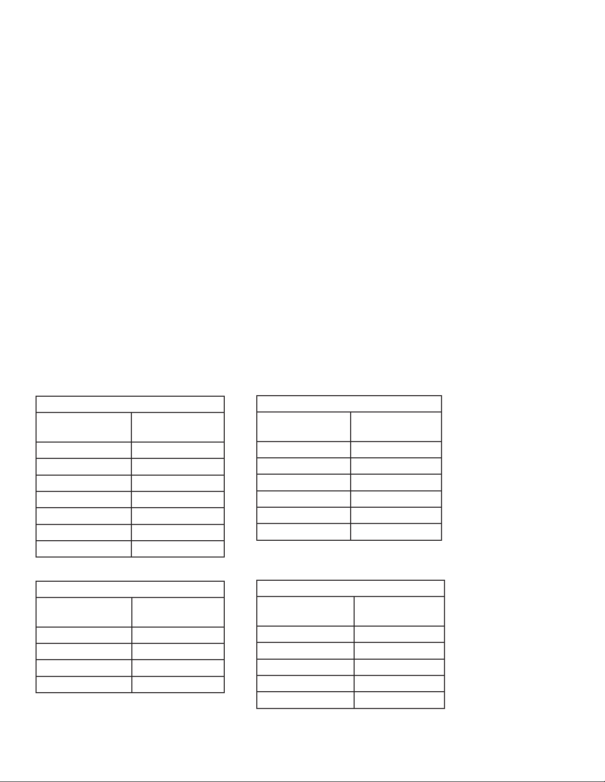
Maximum Specific Gravity for Non-Overloading Applications
3450 rpm (60 Hz)
Closed Impeller
Diameter
7.25” (184.2 mm) 1.0
7” (177.8 mm) 1.1
6.5” (165.1 mm) 1.5
6” (152.4 mm) 1.8
5.5” (139.7 mm) 1.8
5” (127.0 mm) 1.8
4.5” (114.0 mm) 1.8
3450 rpm (60 Hz)
Open Impeller
Diameter
6” (152.4 mm) 1.5
5.5” (139.7 mm) 1.8
5” (127.0 mm) 1.8
4.5” (114.0 mm) 1.8
Maximum
Specific Gravity
Maximum
Specific Gravity
Closed Impeller
Diameter
184.2 mm (7.25”) 1.35
177.8 mm (7”) 1.6
165.1 mm (6.5”) 1.8
152.4 mm (6”) 1.8
139.7 mm (5.5”) 1.8
127.0 mm (5”) 1.8
Open Impeller
Diameter
181.0 mm (7.13”) 1.35
177.8 mm (7”) 1.5
165.1 mm (6.5”) 1.75
152.4 mm (6”) 1.8
139.7 mm (5.5”) 1.8
2900 rpm (50 Hz)
Maximum
Specific Gravity
2900 rpm (50 Hz)
Maximum Specific
Gravity
6
Page 7

DB22 Assembly, Installation and Operation
Unpacking and Inspection
Unpack the pump and examine for any signs of shipping damage. If damage is detected, save the packaging and notify the
carrier immediately.
Section I - Assembly
Tools Required:
3/8” Allen wrench or ballpoint hex socket, 3/16” Allen wrench,
19 mm hex socket, metric socket set (for pumps with IEC outer
drives)
Pumps with Motors
Proceed to “Installation” Section
Pumps Without Motors
NOTE: All motors must have motor feet
1. Remove the pump, drive magnet assembly and hardware
package from the carton. For 184TC motors proceed to
step 3.
CAUTION: Keep away from metallic particles, tools and
electronics. Drive magnets MUST be free of metal chips.
WARNING: Keep the drive magnet away from the open end
of the motor adapter and barrier. Strong magnetic attraction
could allow the drive hub to enter the motor adapter resulting in injury or damage.
2. For 213/215 NEMA motors only
Install the o-ring (item 10A) in the groove in the motor
adapter. Use small amount of petroleum jelly (or silicone
grease on EPDM o-rings) to help hold the o-ring in place.
Install the larger female rabbet portion of the motor adapter
flange (item 10) on the motor face. Align the holes in the
adapter with the holes in the motor face. See figure 1.
Flange hole thread size:
90 B5 = M10 x 1.5
100/112 B5 = M12 x 1.75
132 B5 = M12 x 1.75
Torque bolts to the following:
90/100/112 B14 frame (M8) = 130 in-lb (14.7 N-m)
132 B14 (M10) frame (M10) = 240 in-lb (27.1 N-m)
90 frame B5 (M10) = 240 in-lb (27.1 N-m)
100/112/132 B5 (M12) = 480 in-lb (54.3 N-m)
Figure 1
3. Coat the motor shaft with anti-seize compound. Insert key
supplied with motor into keyway on motor shaft.
NOTE: Make sure the motor shaft is clean and free of burrs.
The outer drive is precision machined and has a bore tolerance of +.0005/-0 inch.
4. Slide the outer drive magnet assembly (item 9) onto the motor shaft until the motor shaft contacts the snap ring in the
bore of the drive. Figures 2 and 3.
For 90, 100/112, & 132 with B5 flange motors
Install flange (item 10) on motor with the side with pockets (depressions) towards the motor face. Align (4) holes
in the adapter with the holes in the motor face. Install (4)
customer supplied bolts, lock washers and flat washers through the motor adapter into the motor face.
For 90 and 132 with B14 flange & 145TC motors
Install flange (item 10) on motor with pockets (depressions) side towards the motor face. Align (4) holes in the
adapter with the holes in the motor face. Install (4) bolts,
lock washers and flat washers (items 20, 21, 22) through
the motor adapter into the motor face. See figure 1.
For 100/112 with B14 flange motors
Install flange (item 10) on motor with pockets (depressions)
towards the pump motor adapter (item 8). Align (4) holes
in the adapter with the holes in the motor face. Install
(4) bolts, lock washers and flat washers (items 20, 21,
22) through the motor adapter into the motor face.
Figure 2 Figure 3
WARNING: Be careful, magnets will try to attract tools.
Metric Motors: Secure the drive to the motor shaft using
bolt, lock washer and flat washer (items 17, 18, 19). Thread
the bolt into the end of the motor shaft (while holding the
outer drive to prevent it from turning). See figure 4.
Tighten the bolt to the following:
• 90 frame (M8) = 130 in-lb (14.7 N-m)
• 100/112 frame (M10) = 240 in-lb (27.1 N-m)
• 132 frame (M12) = 480 in-lb (54.3 N-m)
NEMA Motors: Install set screws (item 9B) into threaded
holes on the side of the outer drive magnet assembly. Using
a 3/16” Allen wrench, tighten to 228 in-lbs (25.8 N-m). See
figure 5.
7
Page 8

Figure 4
Figure 5
5. Install the pump end on the motor/drive magnet assembly.
NOTE: If the pump has the optional o-ring sealing option
(available on 184 and 215 frame pumps only), install the
o-ring (item 8B) in the groove in the motor adapter (motor end). Use small amount of petroleum jelly (or silicone
grease on EPDM o-rings) to help hold the o-ring in place.
Place the motor/drive on a flat surface with the drive and
motor face hanging over the bench surface. Secure the motor to the bench.
Firmly grab the pump and slide over the outer drive magnet
until the motor adapter is seated in the rabbet of the motor
(184TC) or the motor adapter flange. The last 4-5” (10-12
cm) will have strong magnetic attraction between the pump
and outer drive magnet. See figures 6 and 7.
NOTE: The clearance between the motor adapter and drive
magnet is tight (about .010”/.254 mm).
Section II - Installation
Mounting – Pump foot should be securely fastened to a solid
foundation. If the pump was received with plastic shipping shims,
these may be used as additional support for the motor feet.
CAUTION: The NPSH available to the pump must be
greater than the NPSH required. NPSH available should be
two feet (.6 meters) greater than NPSH required.
• Install the pump as close to the suction source as possible.
• Support the piping independently near the pump to eliminate
any strain on the pump casing. In addition, the piping should
be aligned to avoid placing stress on the pump casing.
• The suction side of the pump should be as straight and
short as possible to minimize pipe friction.
• The suction line should not have any high spots. This can
create air pockets that can reduce pump performance. The
suction piping should be level or slope slightly upward to the
pump.
• If flexible hose is preferred over pipe, use a reinforced hose
rated for the proper temperature, pressure and is chemically
resistant against the fluid being pumped.
• The suction valve must be completely open to avoid restricting the suction flow.
• When installing pumps with flanges, we recommend use
of low seating stress gaskets such as Gore-Tex or Gylon
(expanded PTFE).
Figure 6
Figure 7
6. Secure the pump to the motor using (4) 1/2” socket head
cap screws, lock washers and flat washers (items 14, 15,
16). Use 3/8” Allen wrench or 3/8” hex socket on universal
joint. See figures 8 and 9.
Figure 8
Figure 9
7. Rotate the motor fan to ensure that there is no binding in
the pump.
8. Proceed to Installation Section
Motor/Electrical
Install the motor according to NEC requirements and local electrical codes. The motor should have an overload protection circuit.
Wire the motor for clockwise rotation when facing the fan end of
the motor.
CAUTION: Do not operate the pump to check rotation until
the pump is full of liquid.
Check all electrical connections with the wiring diagram on the
motor. Make sure the voltage, frequency, phase and amp draw
comply with the supply circuit.
To verify correct rotation of the motor:
1. Install the pump into the system.
2. Fully open the suction and discharge valves.
3. Allow fluid to flow into the pump. Do not allow the pump to
run dry (ceramic, PTFE and silicon carbide bushings can’t be
run dry without damage to pump components).
4. Jog the motor (allow it to run for 1-2 seconds) and observe
the rotation of the motor fan. Refer to the directional arrow
molded into the pump casing if necessary.
NOTE: A pump running backwards will pump but at a greatly
reduced flow and pressure.
8
Page 9

Section III - Start-up and Operation
Section IV - Maintenance
Start-up and Operation
1. This pump must be filled from a flooded suction tank (gravity) or primed with liquid from an outside source. The DB22
is not self-priming.
2. Open the inlet (suction) and discharge valves completely
and allow the pump to fill with liquid.
3. Close the discharge valve.
4. Turn the pump on. Slowly open the discharge valve. Adjust
the flow rate and pressure by regulating the discharge
valve. Do not attempt to adjust the flow with the suction
valve.
Shutdown
1. Use the following procedure to shutdown the pump.
2. Slowly close the discharge valve.
3. Turn off the motor.
4. Close the suction valve.
Flush Systems
CAUTION: Some fluids react with water; use compatible
flushing fluid.
1. Turn off the pump.
2. Completely close the suction and discharge valves
3. Connect flushing fluid supply to flush inlet valve.
4. Connect flushing fluid drain to flush drain valve.
5. Open flushing inlet and outlet valves. Flush system until the
pump is clean.
Optional Drain Installation
1. Remove the impeller housing (item 1) from the pump assembly.
2. Clamp the impeller housing to a drill press table.
3. Using a 7/16” drill and the molded boss as a guide, drill
completely through the molded boss into the interior of the
impeller housing.
CAUTION: Do not tap too deep or the impeller housing may
be damaged.
4. Using a ¼” NPT tap, tap the hole in the molded boss to the
appropriate depth.
5. Install the drain plug or valve, being careful not to overtighten.
Recommended maintenance schedule
The recommended maintenance schedule depends upon the
nature of the fluid being pumped and the specific application.
If the pump is used on a clean fluid, it is recommended that the
pump be removed from service and examined after six months
of operation or after 2,000 hours of operation. If the pump is
used on fluids with solids, high temperatures or other items
that could cause accelerated wear, then this initial examination
should be sooner.
After the initial examination of the internal components and wear
items are measured, a specific maintenance schedule can be
determined. For best results, it is recommended that the pump
be removed from service annually for examination.
Disassembly
WARNING: Rotating Parts. This pump has components that
rotate while in operation. Follow local safety standards for locking out the motor from the power supply during maintenance or
service.
WARNING: Chemical Hazard. This pump is used for transferring many types of potentially dangerous chemicals. Always
wear protective clothing, eye protection and follow standard
safety procedures when handling corrosive or personally harmful
materials. Proper procedures should be followed for draining and
decontaminating the pump before disassembly and inspection of
the pump. There may be small quantities of chemicals present
during inspection.
WARNING: Magnetic force hazard. This pump should only
be disassembled and assembled using the recommended procedures. The magnetic attraction is powerful enough to rapidly
pull the motor end and the wet end together. Do not place
fingers between the mating surfaces of the motor and wet ends
to avoid injuries. Keep the drive magnet and impeller assembly
away from metal chips or particles.
Stop the pump, lock out the motor starter, close all the valves
that are connected to the pump, and drain/decontaminate the
pump.
WARNING: The pump must be thoroughly flushed of any
hazardous materials and all internal pressure relieved prior to
opening the pump. Allow the pump to reach ambient temperatures prior to performing maintenance.
1. Secure the pump/motor to the bench with the adapter foot
hanging over the edge. Remove (4) 1/2” socket head cap
screws, lock washers and flat washers (items 14, 15, 16)
securing the pump to the motor. Use 3/8” Allen wrench or
3/8” hex socket on universal joint.
9
Page 10

2. Firmly grab the motor adapter and
pull straight out to dis-engage the
motor and pump. See figure 10.
NOTE: If the pump has the
optional o-ring sealing option
(available on 184 and 215 frame
pumps only), make sure o-ring (item
Figure 10
8B) does not fall out of the motor adapter (motor end).
3. Place pump on bench with housing (item 1) facing up. Using
a 19 mm socket, remove (10) M12 hex head cap screws, lock
washers and flat washers (items 11, 12, 13). See figure 11.
4. Pull housing straight up to remove. Impeller shaft (item 5)
may be lodged in the front shaft support. Inspect housing for
signs of wear or damage. Look for signs of rubbing, cracked
thrust ring or damage to front shaft support. See figure 12.
5. Remove impeller/inner drive assembly (items 3A, 3, 4, 4A).
8. Remove the o-ring (item 6) from the barrier and inspect for
chemical attack, swelling, brittleness, cuts, etc.
9. Visually inspect the outer drive (item 9) for rubbing, damage,
corrosion or loose magnets.
NOTE: Inspect the o-ring (item 8A), for chemical attack, swelling, brittleness, cuts, etc. Both NEMA and IEC pumps have o-ring
item 8A. If the pump has the optional o-ring sealing option
(available on 184 and 215 frame pumps only), inspect o-ring
item 8B (and item 10A if 215 frame).
Outer Drive Replacement
1. Remove the setscrews (item 9B) from the side of the drive
(NEMA motors) or the bolt, lock washer and flat washer (items
17, 18, 19) from the center of the drive (metric motors).
WARNING: Be careful, tools will want to be attracted to
the magnets.
2. Remove the drive magnet from the motor shaft by gently
prying up from the bottom of the drive.
3. To reinstall the drive or a new drive follow the instructions from
“Section I – Assembly, Pumps without Motors, Steps 3 & 4”.
Figure 11
Figure 12
See figure 13. Inspect impeller and
drive for signs of wear or damage.
Look for signs of rubbing, damage
and wear to the impeller and inner
drive. Check the impeller thrust ring
and bushing for wear. See figure 14.
Figure 13
.780 max.
diameter
.020 min.
groove height
Figure 14
6. Remove the impeller shaft (item 5) from the barrier and check
for signs of cracking, chipping, scoring or wear. See figure 15.
7. Remove the barrier (item 7) from the motor adapter (item 8)
(make sure the spindle has been removed). If necessary,
gently tap on the backside of the barrier with a soft rod
(wood, plastic, etc). Inspect the inside and outside of the
barrier for signs of rubbing. See figure 16.
Thrust Ring Replacement
1. Thrust ring (item 3A) is held in-place with a snap fit ridge.
Using a razor knife or side cutters, cut a notch out of the
thrust ring. Pull ring up and out of the holder. See figures 17
and 18.
2. To reinstall, align the two flats on the thrust ring with the
flats in the bore of the impeller. Using a piece of wood press
into place using an arbor press until the thrust ring is completely seated in the impeller.
Figure 17 Figure 18
Figure 15 Figure 16
10
Page 11

Bushing Replacement
1. To remove the bushing, place the impeller/inner drive
assembly (items 3A, 3, 4, 4A) with the impeller facing up
in an arbor press. If necessary support the bottom of the
assembly with blocks to allow the bushing to fall out. Insert
a 1” (25.4mm) diameter plastic or wooden shaft through the
impeller and press bushing out. See figure 19.
2. To replace bushing, place the assembly on a flat surface
with the impeller thrust ring face down. With the slotted face
of the bushing facing the rear of the inner drive, align the
flat in the bushing with the flat in the inner drive magnet.
See figure 20. Gently push until bushing bottoms out.
5. Carefully install the impeller/inner drive assembly (items 3A,
3, 4, 4A) by sliding it over the impeller shaft in the barrier.
It is normal for the impeller/inner drive to pop up a slight
amount due to magnetic forces. See figures 22 and 23.
Figure 22
Figure 23
6. Install the impeller housing (item 1). Make sure the discharge is in the correct orientation in relation to the motor
adapter pump foot. Align the shaft in the barrier with the
front shaft support in the impeller housing. Press down to
push the impeller/inner drive magnet assembly into position.
Holding the impeller housing with one hand, install and finger-tighten two bolts lock washers and flat washers (items
11, 12, 13) in opposite locations. See figure 24.
Figure 19
Figure 20
Impeller Replacement
1. To remove the impeller from the inner drive magnet, gently
pry off by hand or lightly tap on the back of the impeller.
2. To install a new impeller, place the inner drive magnet assembly face up. Line up the patterns on the impeller with
the ones on the inner drive magnet so they match and press
into place by hand. An arbor press can also be used to press
the impeller on the inner drive. Place a piece of wood over
the top of the impeller thrust ring and push down on the
impeller until it is completely seated in the inner drive.
Reassembly
1. Lubricate the o-ring (item 8A) with a chemically compatible
lubricant and install in the groove in the motor adapter.
2. Install the barrier (item 7) into the motor adapter (item 8).
Press firmly to ensure that the barrier is completely seated.
7. Install the remaining bolts, lock
washers and flat washers finger
tight.
8. Using a 19 mm socket, tighten
all the bolts evenly using a star
pattern. Tighten to 240 in-lb
(27.1 N-m)
9. Reinstall the pump on the motor/
Figure 24
drive magnet following instructions from “Section I – Assembly, Pumps without Motors,
Steps 5 & 8”.
3. Install o-ring (item 6) in groove in
barrier.
4. Install impeller shaft (item 5) into
barrier by aligning flats on the
shaft with the ones in the barrier.
Make sure it is completely seated.
See figure 21.
Figure 21
11
Page 12
DB22 PART NUMBER EXPLANATION
NOTE: Pump end includes wetted components, drive magnet and motor adapter; wet end includes wetted components only.
Part Number Explanation
Base model number contains standard components. Where standard components aren’t suitable, add the alternative component
code letter after the base model number to substitute components. Example: DB22P-E-U-21 is constructed of the listed base model
components except it has an EPDM O-ring, union connections, and a 213TC motor adapter.
Alternative Components Price Adders
Component Base Alternative Code
The model number is on the serial number label
located on the motor adapter. The model number
contains a base model that features certain standard components. Compare the model number
on the pump to the adjacent chart to determine
if the pump contains any alternate components.
Model numbers containing “P” have primary
components molded from polypropylene. Model
numbers containing “V” have primary components molded from PVDF.
Base Model Numbers: DB22P, DB22V
Bushing Carbon
O-ring Viton
Connection NPT
Impeller Style Closed
Impeller
Note: Impellers 1-7 are closed (50 and 60 Hz); 8-11 are open (60 Hz); 12-16 are open (50 Hz)
Magnet
(Upgrade for
specific gravity
corrections)
1 (60 Hz)
7.25”
8-pole
Up to 13 HP (60 Hz);
7.5 kW (50 Hz)
or PTFE T
EPDM E
or
or
Open - see 8-16 below (8-11 60 Hz/ 12 - 16 50 Hz)
3C 4 4A 4b 4C 5 5A 5B 5C
6.13” 6.00” 5.88” 5.75: 5.63” 5.50” 5.38” 5.25” 5.13”
6 6A 6B 6c 7 8 8A 8B 8C
5.00” 4.88” 4.75” 4.63” 4.50” 6.00” 5.88” 5.75” 5.63”
or
9 9A 9B 9C 10 10A 10B 10C 11
5.50” 5.38” 5.25” 5.13” 5.00” 4.88” 4.75” 4.63” 4.50”
12 13 13A 13B 13C 14 14A 14B 14C
7.13” 7.00” 6.88” 6.75” 6.63” 6.50” 6.38” 6.25” 6.13”
15 15A 15B 15C 16
6.00” 5.88” 5.75” 5.63” 5.50”
or No Upgrade Available.
Simriz S
Kalrez K
BSP B
Union U
Steel Enforced Flange Fs
2” x 2” FRP flange Ff
3” x 2” FRP flange 3 x 2
1A 2 2A 2B 2C 3 3A 3B
7.13” 7.00” 6.88” 6.75” 6.63” 6.50” 6.38” 6.25”
Motor Adaptor
Specials Not Standard
Motor Not Standard
182-184TC NEMA
145TC NEMA 145
213-215TC NEMA 21
IEC 90/B14 94
IEC 100/B14 04
IEC 112/B14 24
or
SiC bushing/impeller thrust ring/shaft Si
12
Contact factory or distributor
IEC 132/B14 34
IEC 90/B5 95
IEC 100/B5 05
IEC 112/B5 25
IEC 132/B5 35
Gas engine mounting Ge
SiC bushing/shaft Ss
Hastelloy shaft Hs
Titanium Hardware Ti
Non-sparking ring Ns
O-ring vapor protection kit Viton
(NEMA)
O-ring vapor protection kit EPDM
(NEMA)
Vv
Ve
Page 13

DB22 EXPLODED VIEW PARTS DIAGRAM
13
Page 14

DB22 Spare Parts List
Item Qty Description
Housing
NPT threads & ceramic ring 106403 106403-1
BSP threads & ceramic ring 106403-2 106403-3
FRP flanges 2"x2" & ceramic ring 106478 106478-1
FRP flanges 3"x2" & ceramic ring 107115 107115-1
Steel flanges 2"x2" & ceramic ring 106478-2 106478-3
1
3A
4A
8A
1
2
1
3
1
1
4
1
1
5
1
6
1
7
1
8
1
1
Unions & ceramic ring 106481 106481-1
NPT threads & SiC ring (optional) 106471 106471-1
BSP threads & SiC ring (optional) 106471-2 106471-3
FRP flanges 2"x2" & SiC ring (optional) 106748 106748-1
FRP flanges 3"x2" & SiC ring (optional) 108033 108033-1
Steel flanges 2"x2" & SiC ring (optional) 106748-2 106748-3
Unions & SiC Ring (optional) 106755 106755-1
Discharge O-ring (BSP housings only)
EPDM
FKM
Simriz
Kalrez
Impeller Assembly with Thrust Ring
Impeller Thrust Ring Only
Closed impeller - Fluorosint
Closed impeller - SiC (optional)
Open impeller - Fluorosint
Open impeller - SiC (optional)
Impeller Drive Assembly
w/ carbon bushing (standard)
w/ PTFE bushing (optional)
w/ SiC bushing (optional)
Impeller Bushing Only
Carbon (standard)
Filled PTFE (optional)
Ceramic (optional)
SiC (optional)
Impeller Shaft
Ceramic (standard)
SiC (optional)
Hastelloy C (optional)
Housing O-ring
FKM (standard)
EPDM (optional)
Simriz (optional)
Kalrez (optional)
Barrier
Motor Adapter
Standard
ATEX
Front Motor Adapter O-Ring
Buna
EPDM
FKM
Pump Material
Polypropylene PVDF
105084
105083
106948
106947
See DB22 Impeller Assemblies Table
J103899
J104170
J101460
J101460-1
106476 106476-1
106476-2 106476-3
106476-4 106476-5
J103917-1
106757
106757-2
106757-1
106450
106450-1
106450-2
106764
106765
106767
106766
106400 106400-1
106414-1 106414-2
106794 106794-1
106844
106845
106846
14
Page 15

DB22 Spare Parts List - con’t
Item Qty Description
Rear Motor Adapter O-Ring (NEMA motors only)
8B
1
Buna 106847
EPDM 106848
FKM
Outer Drive Magnet Assembly with Retaining Ring
182/184TC frame (includes set screws) 106453
143/145TC frame(includes set screws) 106457-3
9
1
213/215TC frame (includes set screws)
90 frame
100/112 frame
132 frame
Retaining Ring Only
182/184TC frame
143/145TC frame
9A
1
213/215TC frame
90 frame
100/112 frame
132 frame
9B
2
Set Screws
NEMA motor only
Motor Adapter Flange
213/215TC frame
90 B14 frame
10
1
90 B5 frame
100/112 B14 and 143/145TC frame
100/112 B5 frame
132 B14 frame
132 B5 frame
Motor Adapter Flange O-Ring (NEMA 213/215 Frame Motors Only)
10A
1
Buna
EPDM
FKM
Pump Material
Polypropylene PVDF
106849
106453-1
106457
106457-1
106457-2
105710
105709
106454
105712
105710
106468
J101084
106775 106775-1
106781 106781-1
106780 106780-1
106777 106777-1
106776 106776-1
106779 106779-1
106778 106778-1
108165
108166
108167
15
Page 16

Hardware- All DB22 Models
Item Qty Description Stainless Steel Titanium
11
12
13
Housing Bolt
10
Housing Lock Washer
10
Housing Flat Washer
10
106501
106503 106504
106505
Motor Adapter Bolt
14
15
16
4
All frame sizes except 213/215TC
213/215TC
Motor Adapter Lock Washer
4
Motor Adapter Flat Washer
4
106495 106498
106511 106512
J101023 105762
106497 106500
Drive Bolt (IEC Only)
17
1
90 frame
100/112 frame
132 frame
105770 105771
105774 105775
106507 106508
Drive Lock Washer (IEC Only)
18
1
90 frame
100/112 frame
132 frame
J102282 J103847
105757 105758
106503 106504
Drive Flat Washer (IEC Only)
19
1
90 frame
100/112 frame
132 frame
105722 105772
J101360 106200
106509 106510
Motor Adapter Flange Bolt (for IEC with B14 flange and 143/145TC Frames Only)
108029 106513
105589 106514
105774 105775
J101000 107740
20*
90 frame
4
100/112 frame
132 frame
143/145TC frame
Motor Adapter Lock Washer (for IEC with B14 flange only)
21*
4
90 frame
100/112 frame
132 frame
J102282 J103847
J102282 J103847
105757 105758
Motor Adapter Flat Washer (for IEC with B14 flange only)
22*
4
90 frame
100/112 frame
132 frame
*Customer must supply motor adapter flange bolt, lock washer and flat washer for IEC frame pumps with B5 flanges.
J101293 J103845
J101293 J103845
N/A N/A
106502
106506
16
Page 17

Thrust
Ring
PTFE
SiC
Thrust
Ring
PTFE
SiC
Thrust
Ring
PTFE
SiC
Thrust
Ring
PTFE
SiC
Thrust
Ring
PTFE
SiC
DB22 Impeller Assemblies
Closed Style
Impeller
Material
Polypro 106472 106472-14 106472-2 106472-16 106472-18 106472-20 106472-4 106472-22 106472-24 106472-26 106472-6 106472-28
PVDF 106472-1 106472-15 106472-3 106472-17 106472-19 106472-21 106472-5 106472-23 106472-25 106472-27 106472-7 106472-29
Polypro 106473 106473-14 106473-2 106472-16 106473-18 106473-20 106473-4 106473-22 106473-24 106473-26 106473-6 106473-28
PVDF 106473-1 106473-15 106473-3 106472-17 106473-19 106473-21 106473-5 106473-23 106473-25 106473-27 106473-7 106473-29
Impeller
Material
Polypro 106472-30 106472-32 106472-8 106472-34 106472-36 106472-38 106472-10 106472-40 106472-42 106472-44 106473
PVDF 106472-31 106472-33 106472-9 106472-35 106472-37 106472-39 106472-11 106472-41 106472-43 106472-45 106472-13
Polypro 106473-30 106473-32 106473-8 106473-34 106473-36 106473-38 106473-10 106473-40 106473-42 106473-44 106473-12
PVDF 106473-31 106473-33 106473-9 106473-35 106473-37 106473-39 106473-11 106473-41 106473-43 106473-45 106473-13
Impeller
Material
Polypro 106469-6 106469-25 106469-28 106469-30 106469-8 106469-32 106469-34 106469-36 106469-10 106469-38 106469-40 106469-42
PVDF 106469-7 106469-27 106469-29 106469-31 106469-9 106469-33 106469-35 106469-37 106469-11 106469-39 106469-41 106469-43
Polypro 106470-6 106470-26 106470-28 106470-30 106470-8 106470-32 106470-34 106470-36 106470-10 106470-38 106470-40 106470-42
PVDF 106470-7 106470-27 106470-29 106470-31 106470-9 106470-33 106470-35 106470-37 106470-11 106470-39 106470-41 106470-43
Impeller
Material
Polypro 106469-12 106469 106469-2 106469-14 106469-16 106469-18 106469-4 106469-20 106469-22 106469-24 106469-6 106469-26
PVDF 106469-13 106469-1 106469-3 106469-15 106469-17 106469-19 106469-5 106469-21 106469-23 106469-25 106469-7 106469-27
Polypro 106470-12 106470 106470-2 106470-14 106470-16 106470-18 106470-4 106470-20 106470-22 106470-24 106470-6 106470-26
PVDF 106470-13 106470-1 106470-3 106470-15 106470-17 106470-19 106470-5 106470-21 106470-23 106470-25 106470-7 106470-27
Impeller
Material
Polypro 106469-28 106469-30 106469-8
PVDF 106469-29 106469-31 106469-9
Polypro 106470-28 106470-30 106470-8
PVDF 106470-29 106470-31 106470-9
#1 #1A #2 #2A #2B #2C #3 #3A #3B #3C 4 #4A
7.25" 7.13" 7.00" 6.88" 6.75" 6.63" 6.50" 6.38" 6.25" 6.13" 6.00" 5.88"
#4B #4C #5 #5A #5B #5C 6 #6A #6B #6C 7
5.75" 5.63" 5.50" 5.38" 5.25" 5.13" 5.00" 4.88" 4.75" 4.63" 4.50"
Open Style
#8 #8A #8B #8C #9 #9A #9B #9C #10 #10A #10B #10C
6.00" 5.88" 5.75" 5.63" 5.50" 5.38" 5.25" 5.13" 5.00" 4.88" 4.75" 4.63"
#11 #12 #13 #13A #13B #13C #14 #14A #14B #14C #15 #15A
4.50" 7.13" 7.00" 6.88" 6.75" 6.63" 6.50" 6.38" 6.25" 6.13" 6.00" 5.88"
#15B #15C #16
5.75" 5.63" 5.50"
17
Page 18

Troubleshooting
Excessive Power Consumption
General Notes:
• Do not pump liquids containing ferrous metal fines.
• If magnets decouple, stop pump immediately. Operating the
pump with the magnets decoupled will eventually weaken
the magnets.
• Contact our Technical Service Department If you have any
questions regarding product operation or repair:
Phone: 1-800-888-3743
E-mail: techservice@finishthompson.com
No or Insufficient Discharge
• Air leaks in suction piping
• Pump not primed
• System head higher than anticipated
• Closed valve
• Viscosity or specific gravity too high
• Motor too large for magnet coupling rating (magnets uncoupled)
• Suction lift too high or insufficient NPSH
• Clogged suction line or impeller vanes
• ·Motor rotation incorrect (correct rotation when viewed from
the fan end is clockwise)
Insufficient Pressure
• Air or gas in liquid
• Impeller diameter too small
• System head lower than anticipated
• Motors speed insufficient (too low) or motor rotation incorrect (correct rotation when viewed from the fan end is
clockwise)
Loss of Prime
• Leak in suction piping
• Foot valve or suction opening not submerged enough
• Foot valve too small or leaking
• Air or gas in liquid
• Foreign matter in impeller
• Leaking valve. Suction lift too high or insufficient NPSHa.
• Head lower than rating
• Excessive flow
• Specific gravity or viscosity too high.
Vibration/Noise
• Loose magnet
• Drive magnet rubbing
• Pump cavitating from improper suction or feed
• Motor or piping not properly secured
• Foreign object in impeller
Section V - Warranty
Finish Thompson, Inc (manufacturer) warrants this pump product
to be free of defects in materials and workmanship for a period
of five years from date of purchase by original purchaser. If a
warranted defect, which is determined by manufacturer’s inspection, occurs within this period, it will be repaired or replaced
at the manufacturer’s option, provided (1) the product is submitted with proof of purchase date and (2) transportation charges
are prepaid to the manufacturer. Liability under this warranty is
expressly limited to repairing or replacing the product or parts
thereof and is in lieu of any other warranties, either expressed
or implied. This warranty does apply only to normal wear of the
product or components. This warranty does not apply to products or parts broken due to, in whole or in part, accident, overload, abuse, chemical attack, tampering, or alteration. The warranty does not apply to any other equipment used or purchased
in combination with this product. The manufacturer accepts no
responsibility for product damage or personal injuries sustained
when the product is modified in any way. If this warranty does
not apply, the purchaser shall bear all cost for labor, material and
transportation.
Manufacturer shall not be liable for incidental or consequential
damages including, but not limited to process down time, transportation costs, costs associated with replacement or substitution
products, labor costs, product installation or removal costs, or
loss of profit. In any and all events, manufacturer’s liability shall
not exceed the purchase price of the product and/or accessories.
Ordering Spare Parts
Spare parts can be ordered from your local distributor. Always
refer to the pump model to avoid error.
Literarture I.D. No. FT08-1023H
Part Number 106782, Rev 12, 4-15-13
 Loading...