

Page 1
1
Page 2

EU Declaration of Conformity
Finish Thompson Inc. hereby declares that the following machine(s) fully comply with the
applicable health and safety requirements as specied by the EC Directives listed. The product
may not be taken into service until it has been established that the drive motor for the centrifugal
pump complies with the provisions of all relevant EC Directives. The complete product complies
with the provisions of the EC Directive on machinery safety provided motors carry CE marking.
This declaration is valid provided that the devices are fully assembled and no modications are
made to these devices.
Type of Device:
Centrifugal Pumps
Models:
AC/AK/AV - 400/500/600/800 DB-3/4/5/5.5/6/6H/7/ GP-11/22/32
8/9/10/11/15/22
KC-3/4/5/5.5/6/6H/8/10/11/22/32 MSKC MSVKC
SP-10/11/15 UC-1516/1518/326 VKC-5.5/6/6H/7/8/10
EC Directives:
Machinery Safety (2006/42/EC)
Applied Harmonized Standards:
EN ISO 12100 Part 1
EN ISO 12100 Part 2
EN 809
Manufacturer:
Finish Thompson Inc.
921 Greengarden Road
Erie, Pennsylvania 16501-1591 U.S.A
Signed,
President
January 1, 2012
2
Page 3

TABLE OF CONTENTS
Description
Important Information ............................................................................................................ 4
Chemical Reaction Disclaimer ................................................................................................ 4
Safety Precautions ................................................................................................................. 4
Installation/Operation Precautions ......................................................................................... 4
Safety Precautions ...............................................................................................................4-5
Temperature Classifications ................................................................................................... 5
DB11/15 Capabilities .............................................................................................................. 5
DB11/15 OIM Section I - Assembly ........................................................................................ 6
DB11/5 OIM Section II - Installation....................................................................................... 7
DB11/15 OIM Section III - Start-up and Operation ................................................................. 8
DB11/15 OIM Section IV - Maintenance ................................................................................. 8
DB11/15 OIM Section V - Disassembly ................................................................................8-11
DB11/15 OIM Section VI - Reassembly ...............................................................................11-12
Part Number Explanation ...................................................................................................... 13
Page Number
DB11/15 OIM Exploded View - Parts Drawing....................................................................... 14
DB11/15 OIM Parts Table ....................................................................................................15-18
DB11/15 OIM Section VII - Troubleshooting ......................................................................... 19
DB11/15 OIM Section VIII - Warranty ................................................................................... 19
NOTE: When you see this icon in the following instructions, click on it to view the
online instructions which are available at www.finishthompson.com.
3
Page 4
IMPORTANT INFORMATION - READ ME FIRST
Model Number and Serial Number
Record the model number and serial number below for future reference. This is important information when ordering replacement parts or when technical
assistance is required. The numbers are found on a label located on the motor adapter.
MODEL NUMBER ___________________________ SERIAL NUMBER __________________________
IMPORTANT NOTICE
U.S. Export Administration Regulations, pursuant to ECCN 2B350, prohibit the export or reexport to certain enumerated countries of sealless centrifugal pumps in
which all wetted materials are constructed from fluoropolymers without first applying for and obtaining a license from the U.S. Bureau of Industry and Security
(BIS). This affects all Finish Thompson magnetic-drive pumps constructed from PVDF or lined with ETFE. Please contact the BIS (www.bis.doc.gov) or Finish
Thompson with questions regarding the Regulations or a list of the countries to which they apply.
Chemical Reaction Disclaimer
The user must exercise primary responsibility in selecting the product’s materials of construction which are compatible with the fluid(s) that come(s) in contact
with the product. The user may consult Finish Thompson, Inc. (Manufacturer) and a manufacturer’s representative/distributor agent to seek a recommendation of
the product’s material of construction that offers the optimum available chemical compatibility.
However neither manufacturer nor agent shall be liable for product damage or failure, injuries, or any other damage or loss arising out of a reaction, interaction or any chemical effect that occurs between the materials of the product’s construction and fluids that come into contact with the product’s components.
Safety Precautions
WARNING: READ THIS MANUAL COMPLETELY BEFORE INSTALLING AND OPERATING THIS UNIT. FAILURE TO FOLLOW THESE PRECAUTIONS CAN RESULT
IN SERIOUS INJURY OR DEATH.
WARNING: Magnetic field hazard. This pump contains powerful magnets. Exposed magnets (pump not connected to motor) produce powerful mag-
netic fields. Individuals with cardiac pacemakers, implanted defibrillators, other electronic medical devices, metallic prosthetic heart valves, internal
wound clips (from surgery), metallic prosthetic devices or sickle cell anemia must not handle or be in the proximity of the magnets contained inside the
pump. Consult a health care provider for specific recommendations before working with this pump.
WARNING: Magnetic force hazard. This pump should only be disassembled and assembled using the recommended procedures. The magnetic at
traction is powerful enough to rapidly pull the motor end and the wet end together. Do not place fingers between the mating surfaces of the motor and
wet ends to avoid injuries. Keep the drive magnet and impeller assembly away from metal chips or particles.
WARNING: When pumping flammable or combustible liquids with a DB Series pump it is important to follow these guidelines:
1. You must use a PVDF pump. PVDF has conductive carbon fibers added which allow it to be grounded when installed in a properly grounded piping
system or when a properly installed grounding strap is attached to a housing bolt. If PVDF is not compatible with the liquid being pumped, you
should consider an ETFE lined UC Series magnetic drive pump.
2. You must select the non-sparking (Ns) bronze bump ring option. The non-sparking ring is pressed into the clamp ring or motor adapter and prevents sparking should the motor bearings fail and the outer mag drive assembly runs out of round.
3. You must select an explosion-proof FTI motor or provide your own explosion-proof motor.
When pumping non-flammable or non-combustible liquids in a hazardous area using a DB Series pump, it is important to take these guidelines:
1. You must select the non-sparking (Ns) bronze bump ring option. The non-sparking ring is pressed into the clamp ring or motor adapter and pre-
vents sparking should the motor bearings fail and the outer mag drive assembly runs out of round.
2. You must select an explosion-proof FTI motor or provide your own explosion-proof motor.
WARNING: Hot surfaces. DB Series pumps are capable of handling liquids with temperatures as high as 220ºF (104ºC). This may cause the outer areas
of the pump to become hot as well and could cause burns.
WARNING: Rotating Parts. This pump has components that rotate while in operation. Follow local safety standards for locking out the motor from the
power supply during maintenance or service.
WARNING: Chemical Hazard. This pump is used for transferring many types of potentially dangerous chemicals. Always wear protective clothing, eye protection
and follow standard safety procedures when handling corrosive or personally harmful materials. Proper procedures should be followed for draining and decon
taminating the pump before disassembly and inspection of the pump. There may be small quantities of chemicals present during inspection.
WARNING: The pump and associated components are heavy. Failure to properly support the pump during lifting and movement could result in serious
injury or damage to the pump and components.
WARNING: Never run pump at less than minimum flow or with the discharge valve closed. This could lead to pump failure.
Installation/Operation Precautions
CAUTION: This pump should never be operated without liquid in the casing. It is recommended that run dry protection be used. Optional electronic
power monitors are available to help protect against run dry. If the pump has a PTFE, ceramic or silicon carbide bushing, IT CANNOT BE RUN DRY WITH-
4
Page 5
OUT CAUSING DAMAGE TO THE PUMP. However, the pump can operate without liquid in the casing if the pump has a carbon bushing. The exact length
of time the pump can operate dry with a carbon bushing varies with operating conditions and environment.
CAUTION: Never start or operate with a closed suction valve. Never operate with a closed discharge valve.
CAUTION: Always provide adequate NPSHa (net positive suction head available). It is recommended to provide at least 2 feet (61 cm) above the NPSHr
(net positive suction head required).
CAUTION: If pump is used on variable speed drive, do not exceed the frequency for which the pump was designed (for example, if the pump is a 50 Hz
model, do not exceed 50 Hz)
.
CAUTION: Use of a power monitor is strongly recommended for pumps with ceramic, PTFE or silicon carbide bushings. The power monitor will stop
the pump and help prevent damage if the pump should run dry. ATEX certified pumps MUST use a power monitor
.
Safety Precautions for ATEX Pumps
CAUTION: Proper o-ring material must be chosen for the fluid being pumped. Improper material selection could lead to swelling and be a possible source
of leaks. This is the responsibility of the end user.
WARNING: The pump must be checked for leaks on a regular basis. If leaks are noticed, the pump must be repaired or replaced
immediately.
WARNING: The pump must be cleaned on a regular basis to avoid dust buildup greater than 5 mm.
WARNING: ATEX pumps must use a power monitor, flow switch, pressure switch or similar device to help protect against dry running, closed discharge
valve and decoupling. Any of these conditions could lead to a rise in surface temperature of the pump.
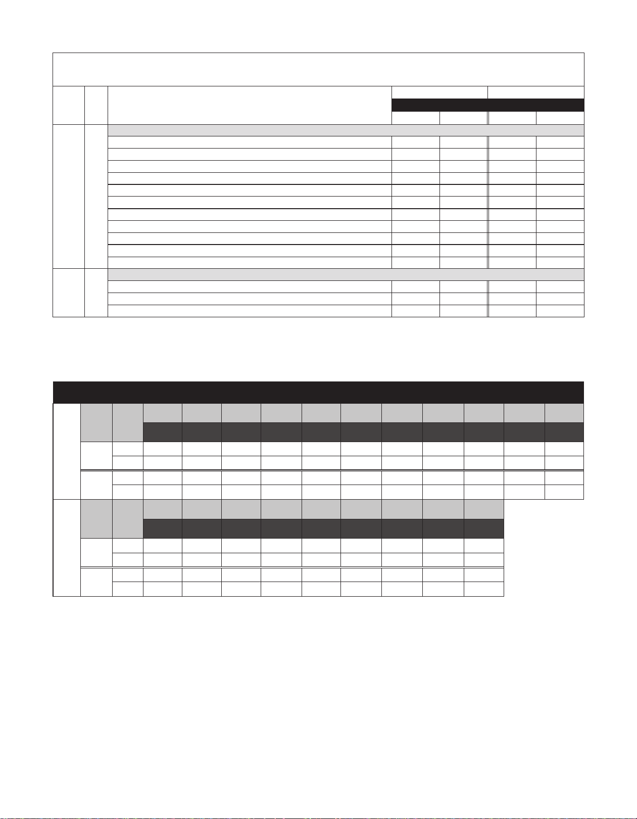
Temperature Classification
The surface temperature of the DB Series pumps depends upon the temperature of the fluid that is being pumped. The following chart lists different fluid
temperatures and the corresponding pump surface temperature.
Fluid Temperature Maximum Surface
Temperature
70º F (27º C) 131º F (55º C) T6 85º C
170º F (85º C) 168º F (76º C) T5 100º C
220º F (104º C) 183º F (84º C) T4 135º C
Temperature
Class
Maximum Allowable
Surface Temperature
DB11/15 Capabilities
Maximum Working Pressure: 90 psi (6.2 bar) (models with o-ring)
Maximum Working Pressure: 50 psi (3.5 bar) (models with Gylon
Maximum Viscosity: 150 cP
Maximum Temperature: Polypropylene -180º F (82º C); PVDF – 220º F (104º C)
Note: Maximum temperature is application dependent.
Consult a chemical resistance guide or the chemical manu facturer for chemical compatibility and temperature limits.
Maximum Noise Level: 78 dBA (pump only)
Solids: Maximum particle size is 100 microns for slurries and 1/64” (.4 mm) for infrequent particles. Maximum hardness is 80 HS. Maximum concentration
is 10% by weight. If solids are being pumped, it is recommended that the pump have either ceramic or for best results, silicon carbide components. Pumping
solids may lead to increased wear.
Minimum Allowable Flow Rate:
Do not allow the flow rate to drop below the minimum flow rate listed in the chart below:
Model 3450 rpm 1725 rpm 2900 rpm 1450 rpm
DB11 4 gpm (.9 m3/hr) 2 gpm (.5 m3/hr) .76 m3/hr (3.4 gpm) .38 m3/hr (1.7 gpm)
DB15 5 gpm (1.1 m3/hr) 2.5 gpm (.6 m3/hr) .95 m3/hr (4.2 gpm) .48 m3/hr (2 gpm)
®
gasket)
Maximum Allowable Motor Power:
Do not exceed the maximum power rating for the pump coupling.
Standard coupling for the DB11 is 6-pole; standard coupling for the DB15 is 8-pole.
6-pole coupling = 2 horsepower (1.5 kW)
8-pole coupling = 3 horsepower (2.2 kW)
10-pole coupling = 5 horsepower (4 kW)
5
Page 6
DB11/15 ASSEMBLY, INSTALLATION & OPERATION
Unpacking and Inspection
Unpack the pump and examine for any signs of shipping damage.
If damage is detected, save the packaging and notify the carrier
immediately.
Section I - Assembly
Pumps with Motors
Proceed to “Installation” Section.
Pumps Without Motors
NOTE: 184TC and 100/112 frame motors must have feet.
Tools Required - Metric socket or wrench set, 9/16” socket
or wrench and 3/16” Allen Wrench (NEMA motors only).
1. Remove the pump, drive magnet assembly and hardware
package from the carton. Do not remove the shipping
plug until after the pump has been installed on the motor.
CAUTION: Keep away from metallic particles, tools, and
electronics. Drive magnets MUST be free of metal chips.
WARNING: Keep the drive magnet away from the open
end of the motor adapter and barrier. Strong magnetic
attraction could allow the drive hub to enter the motor
adapter resulting in injury or damage.
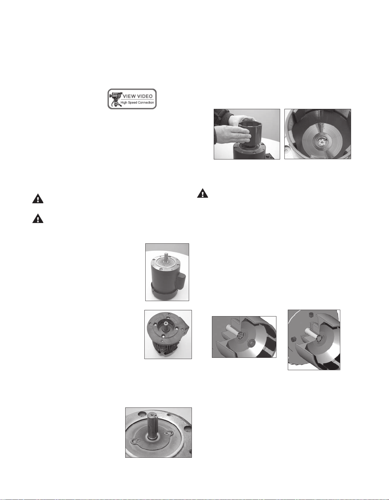
2. Place motor on the fan end. For
56C/145TC and B5 frame motors go to
step 4. See figure 1.
Figure 1
3. For 184 NEMA and IEC motors only -
install the motor adapter flange (item
10) on the motor face using bolts, lock
washers and flat washers (items 21,
22, 23). See figure 2.
NOTE: Make sure the motor shaft is clean and free of
burrs. The outer drive is precision machined and has a
bore tolerance of +.0005/-0 inch.
5. Slide the outer drive magnet assembly (item 9) onto the
motor shaft until the motor shaft contacts the snap ring
in the bore of the drive. Figures 4 and 5.
Figure 4 Figure 5
6. Secure the drive on the motor shaft.
WARNING: Be careful, magnets will try to attract tools.
Metric Motors: Secure the drive to the motor shaft using
bolt, lock washer and flat washer (items 18, 19, 20).
Thread the bolt into the end of the motor shaft (while
holding the outer drive to prevent it from turning). See
figure 6.
Tighten the bolt to the following:
80 frame (M6) = 90 in-lb (10.2 N-m)
90 frame (M8) = 130 in-lb (14.7 N-m)
100/112 frame (M10) = 240 in-lb (27.1 N-m)
NEMA Motors: Install set screws (item 9A) into threaded
holes on the side of the outer drive magnet assembly. Using
a 3/16” Allen wrench, tighten to 228 in-lbs. (25.8 N-m).
See figure 7.
Figure 7 - NEMA Drive
Torque bolts to the following:
80 frame (M6) = 90 in-lb (10.2
N-m)
90/100/112 frame (M8) = 130 in-lb (14.7 N-m)
184 NEMA (1/2”) = 300 in-lb (33.9 N-m)
Note: Apply anti-seize compound on threads of the bolts.
4. Coat the motor shaft with
anti-seize compound. Insert
key supplied with motor into
keyway on motor shaft. See
figure 3.
Figure 3
Figure 2
Figure 6 - IEC Drive
7. For NEMA 56C and 145TC frame motors:
Install o-ring (item 8E) in the groove on the back of the motor
adapter (item 8D). Use petroleum jelly to hold the o-ring in
place during installation. Note: 184TC and metric adapters
do not use this o-ring
6
Page 7
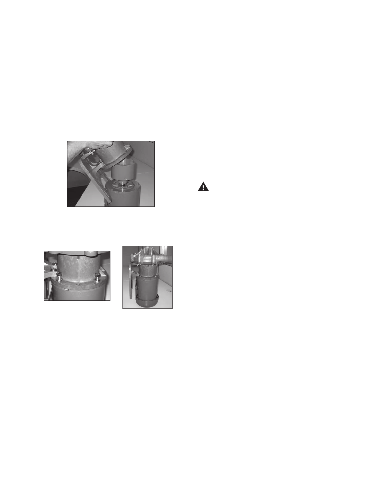
Install the pump end on the motor/drive magnet assembly. With
the motor facing upright, align the pump feet so that the
motor feet and pump feet are on the same side.
Tip the pump end at an angle (discharge is approximately
45º) so that it is just touching the edge of the outer
drive magnet assembly. See figure 8.
Carefully lower the pump onto the drive magnet assembly
by tipping discharge forward to 90º and dropping straight
down. The last 3-4 inches (8-10 cm) before the pump
reaches the motor will have STRONG magnetic attraction
between the pump and outer drive magnet assembly.
Figure 8
8. Secure the pump to the motor with (4) 3/8” bolts, lock washers
and flat washers (items 15,16,17). See figures 9 and 10.
NOTE: Apply anti-seize compound on threads of bolts.
` (3) Use the shorter M6 bolts, lock washers and flat washers
(items 24, 25 and 26) for the rear bolt holes towards the
motor face. Note: Nuts (item 30) are glued into the rear
the motor adapter to help with the installation of the rear
bolts. Make sure the nuts are still in place. See figure 35
on page 10. Tighten bolts to 5 ft-lbs.
9. Rotate the motor fan to ensure there is no binding in the
pump.
10. Proceed to Installation Section
Section II - Installation
Mounting
Pump foot should be securely fastened to a solid foundation.
If the pump was received with plastic shipping shims, these
shims may be used as additional support for the motor feet
(though not required).
Piping
CAUTION: The NPSH available to the pump must be
greater than the NPSH required. Filters, strainers and any
other fittings in the suction line will lower the NPSH avail
able and should be calculated into the application.
• Install the pump as close to the suction source as
possible.
• Support the piping independently near the pump to elimi-
nate any strain on the pump casing. Also, the piping should
be aligned to avoid placing stress on the pump casing.
Figure 9
Figure 10
For NEMA 184 and IEC 80, 90, 100, 112-B14 frame pumps:
NOTE: B5 motors with clearance holes will require customer
supplied hardware. B5 pumps with 100/112 frame do not in clude a pump foot.
Pumps shipped without motors in the above referenced frame
sizes are shipped with the pump foot (item 11) uninstalled
to allow the motor to be connected to the pump.
The pump foot will be installed after the pump has been at-
tached to the motor. Follow pump mounting instructions from
#7 above. Proceed to the foot installation instructions below.
Foot Installation:
(1) Place the pump and motor in an upright position on the
motor fan shroud.
(2) Install the plastic foot (item 11) on to the motor adapter
(item 8D). Use the longer M6 bolts, lock washers and flat
washers (items 24A, 25, and 26) for the front bolt holes
towards the clamp ring. See figure 34 on page 10.
• The suction side of the pump should be as straight and
short as possible to minimize pipe friction.
• Keep bends and valves at least ten pipe diameters away
from the suction and discharge.
• The suction line should be at least as large as the suction
inlet port or one pipe size larger so that it does not affect
the NPSHa. Do not reduce the suction line size.
• The suction line should not have any high spots. This can
create air pockets. The suction piping should be level or
slope slightly upward to the pump.
• A check valve and control valve (if used) should be
installed on the discharge line. The control valve is used
for regulating flow. An isolation valves on the suction and
discharge are used to make the pump accessible for
maintenance. The check valve helps prevent the pump
against damage from water hammer. This is particularly
important when the static discharge head is high.
• If flexible hose is preferred, use a reinforced hose rated
for the proper temperature, pressure and chemical
resistance against the fluid being pumped.
• The suction valve must be completely open to avoid
restricting the suction flow.
7
Page 8

• FTI advises installing a flush system in the piping to allow
the pump to be flushed before it is removed from service.
NOTE: The pump is provided with a provision for a
customer installed ¼” drain in the impeller housing. See
the Drain Installation Section for details.
• For units in a suction lift system, install appropriate piping
in the discharge to allow priming of the pump (DB11/15
models are not self-priming).
• When installing pumps with flanges, we recommend use of
low seating stress gaskets such as Gore-Tex® or Gylon®
(expanded PTFE).
Motor/Electrical
Install the motor according to NEC requirements and local
electrical codes. The motor should have an overload pro-
tection circuit.
Do not attempt to adjust the flow with the suction valve.
5. Use of a power monitor is strongly recommended for pumps
with ceramic, PTFE or silicon carbide bushings. The power
monitor will stop the pump and help prevent damage if the
pump should run dry. ATEX certified pumps MUST use a
power monitor.
Shutdown
Use the following procedure to shutdown the pump.
1. Slowly close the discharge valve.
2. Turn off the motor.
3. Close the suction valve.
Flush Systems
CAUTION: Some fluids react with water; use compatible
flushing fluid.
Wire the motor for clockwise rotation when facing the fan end
of the motor.
CAUTION: Do not operate the pump to check rotation until
the pump is full of liquid.
Check all electrical connections with the wiring diagram on
the motor. Make sure the voltage, frequency, phase and amp
draw comply with the supply circuit.
If utilized, verify that the power monitor has been properly
installed according to the manufacturers instructions.
To verify correct rotation of the motor:
1. Install the pump into the system.
2. Fully open the suction and discharge valves.
3. Allow fluid to flow into the pump. Do not allow the pump
to run dry (ceramic, PTFE and silicon carbide bushings
can’t be run dry without damage to pump components).
4. Jog the motor (allow it to run for 1-2 seconds) and
observe the rotation of the motor fan. Refer to the direc-
tional arrow molded into the pump casing if necessary.
NOTE: A pump running backwards will pump but at a greatly
reduced flow and pressure.
1. Turn off the pump.
2. Completely close the suction and discharge valves.
3. Connect flushing fluid supply to flush inlet valve.
4. Connect flushing fluid drain to flush drain valve.
5. Open flushing inlet and outlet valves. Flush system until
the pump is clean.
Optional Drain Installation
1. Remove the impeller housing from the pump assembly.
2. Clamp the impeller housing to a drill press table.
3. Using a 7/16” drill and the molded boss as a guide, drill
completely through the molded boss into the interior of
the impeller housing. De-burr the hole on the inside of the
impeller housing.
CAUTION - Do not tap too deep or the impeller housing may
be damaged.
4. Using a 1/4” NPT tap, tap the hole in the molded boss
to the appropriate depth.
5. Install the drain plug or valve, being careful not to
overtighten.
Section IV - Maintenance
Recommended maintenance schedule
Section III - Start-up and Operation
1. This pump must be filled from a flooded suction tank (gravity)
or primed with liquid from an outside source. The DB11/15 is
not self-priming.
2. Open the inlet (suction) and discharge valves completely and
allow the pump to fill with liquid.
3. Close the discharge valve.
4. Turn the pump on. Slowly open the discharge valve. Adjust
the flow rate and pressure by regulating the discharge valve.
8
The recommended maintenance schedule depends upon the nature of the fluid being pumped and the specific application. If the
pump is used on a clean fluid, it is recommended that the pump
be removed from service and examined after six months of
operation or after 2,000 hours of operation. If the pump is used
on fluids with solids, high temperatures or other items that could
cause accelerated wear, then this initial examination should be
sooner.
After the initial examination of the internal components and wear
items are measured, a specific maintenance schedule can be
determined. For best results, it is recommended that the pump be
removed from service annually for examination.
Page 9
Section V - Disassembly
WARNING: Rotating Parts. This pump has components
that rotate while in operation. Follow local safety stand-
ards for locking out the motor from the power supply
during maintenance or service.
WARNING: Chemical Hazard. This pump is used for trans-
ferring many types of potentially dangerous chemicals.
Always wear protective clothing, eye protection and follow
standard safety procedures when handling corrosive or per sonally harmful materials. Proper procedures should be fol lowed for draining and decontaminating the pump before
disassembly and inspection of the pump. There may be small
quantities of chemicals present during inspection.
WARNING: Magnetic force hazard. This pump should only
be disassembled and assembled using the recommended
procedures. The magnetic attraction is powerful enough to
rapidly pull the motor end and the wet end together. Do not
place fingers between the mating surfaces of the motor and
wet ends to avoid injuries. Keep the drive magnet and impeller
assembly away from metal chips or particles.
1. Stop the pump, lock out the motor starter, close all the
valves that are connected to the pump, and drain/decon-
taminate the pump.
tors 3 HP (2.2 kW) or larger, place the pump and motor
on the floor. Remove the (4) bolts, lock washers and flat
washers (items 15,16,17) securing the pump to the mo-
tor. See figure 9. Make sure the motor is on the fan end
with the pump facing up. Pull straight up to remove the
pump from the motor. See figure 12.
Figure 12
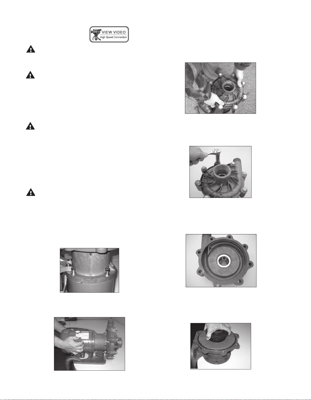
3. Place pump on bench with housing facing up. Remove
(8) 10 mm housing bolts, lock washers and flat washers
(items 12, 13, 14). See figure 13.
WARNING: The pump must be thoroughly flushed of any
hazardous materials and all internal pressure relieved prior
to opening the pump. Allow the pump to reach ambient
temperatures prior to performing maintenance.
2. For pumps with motors 2 horsepower (1.5 kW) or smaller,
securely clamp the pump feet to the bench. Remove the
(4) bolts, lock washers and flat washers (items 15,16,17)
securing the pump to the motor. See figure 9.
Figure 9
Firmly grab the motor and pull straight back to disengage
the motor and pump. See figure 11. For pumps with mo
Figure 13
4. Pull housing (item 1) straight up to remove. Inspect
housing for signs of wear or damage. Look for signs of
rubbing, cracking on thrust ring, or damage to front shaft
support. See figure 14.
Figure 14
5. Remove impeller/inner drive assembly (items 4A, 4, 5, 5A).
Inspect impeller and drive for signs of wear or damage.
Look for signs of rubbing or damage and wear to the im-
peller and inner drive. See figure 15.
Figure 11
Figure 15
9
Page 10

Check the impeller thrust ring and bushing for wear. See
figure 16.
Figure 16
Figure 19
3. To reinstall the drive or a new drive follow the instructions
from Section I - Assembly, Pumps without Motors, steps
4-6.
6. Remove the impeller shaft (item 6) from the barrier and
check for signs of cracking, chipping, scoring or wear.
See figure 17.
Figure 17
7. Remove the barrier (item 7) from the motor adapter (item
8). Make sure the spindle has been removed. Pry the
barrier out with your hand. Inspect the inside and outside
of the barrier for signs of rubbing. See figure 18.
Figure 18
8. Remove the o-ring (item 2) from the barrier and inspect for
chemical attack, swelling, brittleness, cuts, etc.
9. Visually inspect the outer drive (item 9) for rubbing,
damage, corrosion or loose magnets.
Outer Drive Replacement
1. Remove the setscrews (item 9A) from the side of the
drive (NEMA motors) or the bolt, lock washer and flat
washer (items 18, 19, 20) from the center of the drive
(metric motors).
Thrust Ring Replacement
1. Thrust ring (item 4A) is held in-place with a snap fit with a
ridge. Using a razor knife or side cutters, cut a notch out of
the thrust ring. Pull ring up and out of the holder. See
figures 20-21.
Figure 20
Figure 21
2. To reinstall, align the two flats on the thrust ring with the
flats in the bore of the impeller. Using a piece of wood,
press into place using an arbor press until the thrust ring is
completely seated in the impeller.
Bushing Replacement
1. To remove the bushing, place the impeller/inner drive
assembly in an arbor press. Insert a 3/4” diameter plastic
or wood shaft through the eye of the impeller and press
the bushing out.
2. To replace the bushing (item 5A), place the top of the
impeller on an arbor press with the thrust ring face down.
Insert the front of the bushing (figure 22) into the center
of the impeller/inner drive magnet assembly, aligning the
flat on the bushing with the flat in the bore of the inner
drive magnet. Using a soft arbor, press into place until the
bushing reaches the shoulder molded into the inner drive
(figures 23 and 24).
WARNING: Be careful, tools will want to be attracted to
the magnets.
2. Remove the drive magnet from the motor shaft by gently
prying up from the bottom of the drive. See figure 19.
10
Figure 22
Figure 23
Figure 24
Page 11
Impeller Replacement
Caution: Do not damage the outer surface of the inner drive
magnet during impeller replacement.
Using the two slots provided, insert a flat blade screw driver
into them and pry the impeller (items 4, 4A) up from the
body of the inner drive magnet (items 5, 5A). Once a gap has
been established, work around the perimeter to evenly increase
the gap until the impeller can be removed. See figure 25.
Figure 25
To install a new impeller, place the inner drive magnet assem bly face up (splines facing up) on an arbor press. Align the
spines in the impeller with the ones in the bore on the inner
drive magnet. Place a piece of wood over the top of the
impeller thrust ring. Using an arbor press, push down on the
impeller until it is completely seated in the inner drive.
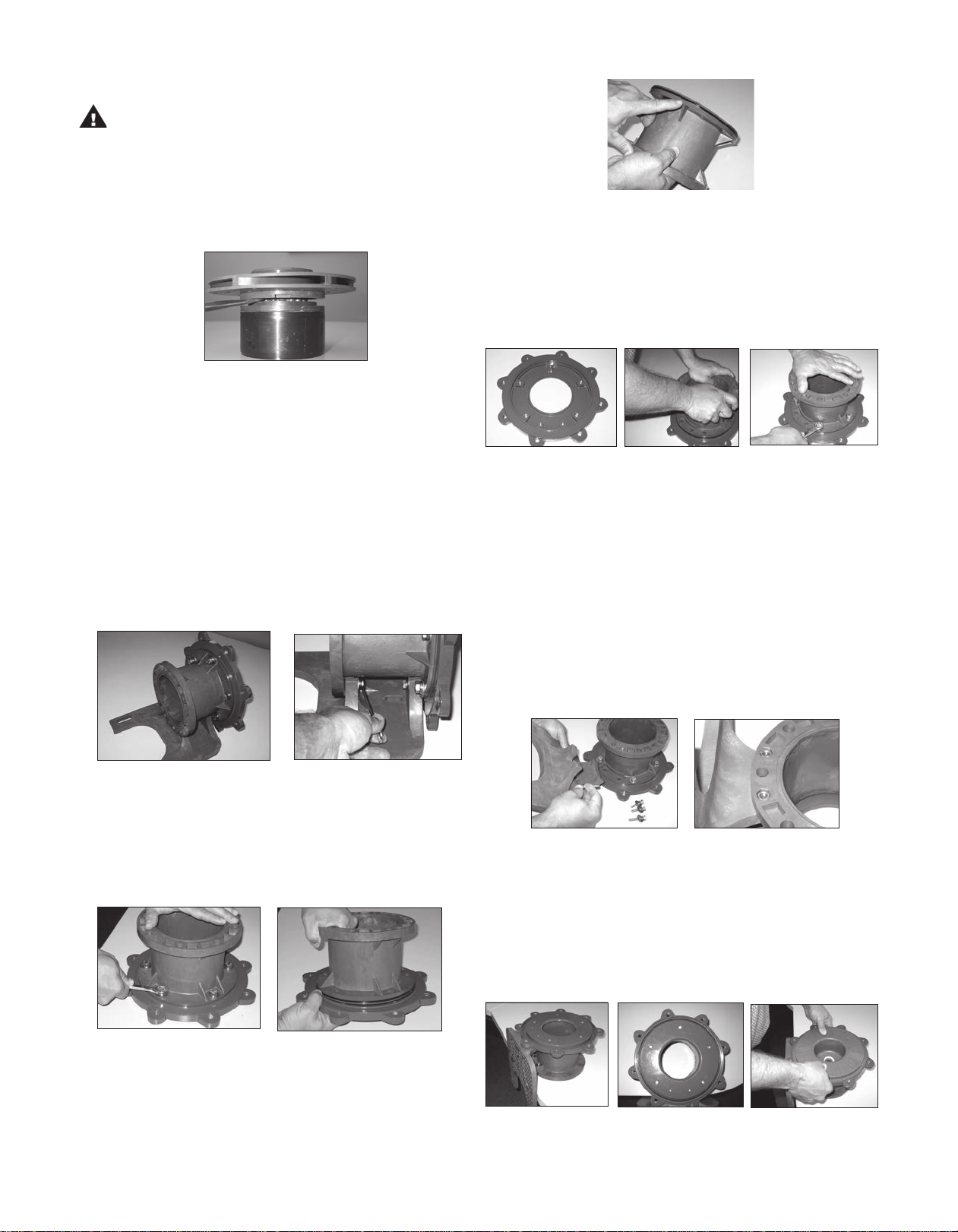
Section VI - Clamp Ring Replacement & Reassembly
1. Inspect the clamp ring. If clamp ring requires replacement, it
is recommended to remove the plastic foot (Item 11) first.
Note: 100/112 frame B5 adapters do not use the foot. See figures
26 & 27. Remove the 4-M6 bolts (items 24 & 24A).
Figure 30
4. Install the new clamp ring. Place the clamp ring on a flat surface.
See figure 31. Align the bolt holes (5 motor adapter and 2 foot bolt
holes) on the clamp ring with the bolt holes on the motor adapter.
Push the motor adapter straight down onto the clamp ring to
seat the o-ring. See figure 32. Install (5) M8 bolts, lock washers
and flat washers (items 29, 28 and 27), and tighten in a star pat tern to 130 in-lb (14.7 N-m). See figure 33.
Figure 31
Figure 32 Figure 33
5. For 56C, 145TC and 80 frame B14, re-install the plastic foot
(item 11) to the motor adapter (item 8D). Use the longer M6
bolts, lock washers and flat washers (items 24A, 25 and 26)
for the front bolt holes towards the clamp ring. See figure
34. use the shorter M6 bolts, lock washers and flat washers
(items 24, 25 and 26) for the rear bolt holes towards the mo tor face. Note: Nuts (item 30) are glued into the rear of the
motor adapter to help with the installation of the rear bolts.
Make sure the nuts are still in place. See figure 35. Tighten
bolts to 5 ft-lbs. (6.7 N-m). For 184 frame, IEC 90, 100/112
frame B14 and 80/90 frame B5, leave the foot off until the mo tor adapter is installed on the motor. This will allow easer ac cess to the bottom bolt hole in the motor adapter.
Figure 26
Figure 27
2. Remove the (5) M8 bolts, lock washers & flat washers (items
29, 28 & 27) from the clamp ring (item 8B). See figure 28.
Remove the clamp ring from the motor adapter. There is a
snug fit between the clamp ring & motor adapter due to the
vapor protection o-ring (item 8C). Carefully pull the two parts
apart. See figure 29.
Figure 28
Figure 29
3. Inspect the motor adapter o-ring (item 8C). If damaged,
replace. If reusable, lubricate it with a chemically compatible
lubricant. See figure 30.
Figure 34 Figure 35
6. Position the motor adapter assembly on a flat surface. If the
foot is installed, allow the feet to hang over the edge. See fig ure 36. Install the o-ring (item 8A) into the groove on the
clamp ring. Lubricate the o-ring with a compatible lubricant.
See figure 37. Install the barrier (item 7) into the clamp ring
motor adapter assembly (items 8A, 8B, 8C, 8D, 27, 28, and
29). Push the barrier straight down until it seats in the clamp
ring. See figure 38.
Figure 36
11
Figure 37 Figure 38
Page 12

7. Install o-ring (item 2). See figure
39.
8. Install impeller shaft (item 6) into
barrier by aligning the flats
on the shaft with the ones in
the barrier. Make sure it is
completely seated. See figure 39.
Figure 39
9. Carefully install the impeller/inner drive assembly (items 4,
4A, 5, 5A) by sliding it over the impeller shaft in the barrier. It is
normal for the impeller /inner drive to pop up a slight amount
due to magnetic forces. See figures 40 and 41.
Figure 40
Figure 41
10. Install the impeller housing (item 1). Make sure the dis
charge is in the correct orientation in relation to pump foot.
Align the shaft in the barrier with the front shaft support in
the impeller housing. Press down to push the impeller/in
ner drive magnet assembly into position. Holding the
impeller housing with one hand, install and finger-tighten
two bolts, lock washers and flat washers (items 12, 13, 14)
in opposite locations. See figure 42.
Figure 42
11. Install the remaining bolts, lock washers and flat washers
finger tight.
12. Tighten all the bolts evenly using a star pattern. Tighten to
20 foot-lbs (27 N-m).
13. Reinstall the pump on the motor/drive magnet following
instructions found in “Assembly, Pumps Without Motors,”
steps 7-10.
12
Page 13

PART NUMBER EXPLANATION
1. Select Base Model (Example: DB11P) *
2. If Standard Components aren’t suitable, enter symbol(s) of alternative components in any order.
Base Model - - - - -
DB11P - E - U - 14
3. Alternative Components - select from below
*The model number is on the serial
number label located on the motor
adapter. The model number contains
a base model that features certain
standard components. Compare the
model number on the pump to the
chart below to determine if the pump
contains any alternate components.
Model numbers containing “P” have
primary components molded from
polypropylene. Model numbers
containing “V” have primary components molded from PVDF.
(Example: DB11P-E-U-14 is a DB11P with EPDM o-ring, unions and 145TC motor adapter.)
Base Model Numbers: DB11P, DB11V,
DB15P, DB15V
13
Page 14

DB11 / DB15 Exploded View - Parts Diagram
14
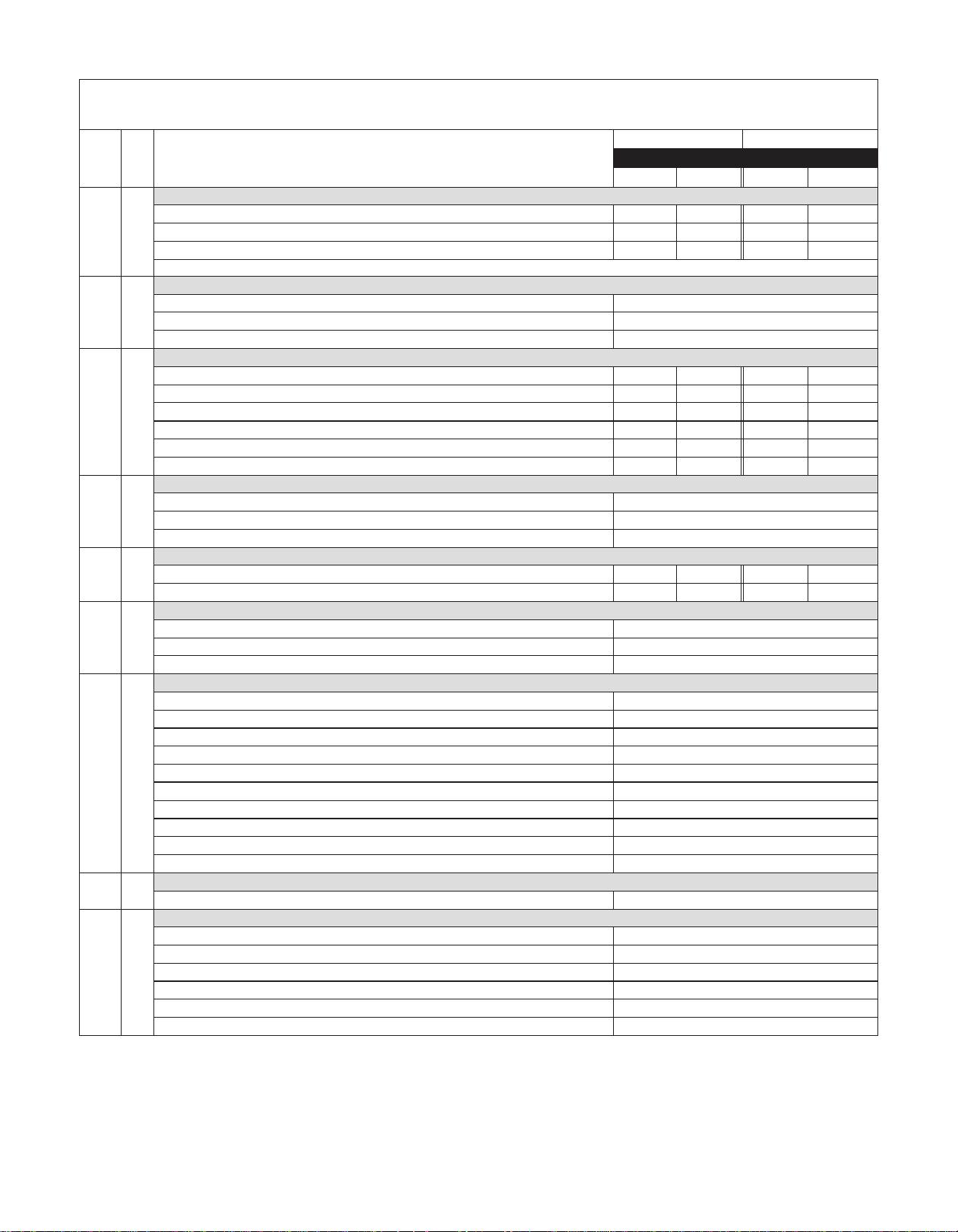
Page 15

Item Qty Description
Standard Housing with Ring
NPT threads & standard alumina ceramic ring 105688-1 105688-3 105739-1 105739-3
BSP threads & standard alumina ceramic ring 105688-5 105688-7 105739-5 105739-7
Steel flanges & standard alumina ceramic ring 105744-1 105744-2 105745-1 105745-2
Fiberglass flanges & standard alumina ceramic ring 105744-5 105744-6 105745-5 105745-6
1 1
2 1
3 1
4 1
4A 1
5 1
5A 1
6 1
7 1
Union & standard alumina ceramic ring 105746-1 105746-3 105747-1 105747-3
NPT threads & optional SiC ring 105903 105903-1 105904 105904-2
BSP threads & optional SiC ring 105903-4 105903-5 105904-4 105904-6
Steel flanges & optional SiC ring 105905 105905-1 105924 105924-1
Fiberglass flanges & optional SiC ring 105905-4 105905-5 105924-4 105924-5
Unions & optional SiC ring 105906 105906-2 105923 105923-2
Housing O-ring
EPDM (optional) 105717
FKM (standard) 105716
Kalrez (optional) 105718
Simriz (optional) 105719
Discharge O-ring (BSP Threaded Housings Only)
EPDM (optional) 105918
FKM (standard) 105919
Kalrez (optional) 105920
Simriz (optional) 105921
Impeller Assembly with Thrust Ring
Impeller Thrust Ring Only
Filled PTFE (standard) 105694-1
Silicon Carbide (optional) 105694-3
Impeller Drive Assembly
6-pole w/ carbon bushing 105913 105913-3 105913 105913-3
8-pole w/ carbon bushing 105913-1 105913-4 105913-1 105913-4
10-pole w/ carbon bushing 105913-2 105913-5 105913-2 105913-5
6-pole w/ PTFE bushing 105913-6 105913-9 105913-6 105913-9
8-pole w/ PTFE bushing 105913-7 105913-10 105913-7 105913-10
10-pole w/ PTFE bushing 105913-8 105913-11 105913-8 105913-11
6-pole w/ alumina ceramic bushing 105913-12 105913-15 105913-12 105913-15
8-pole w/ alumina ceramic bushing 105913-13 105913-16 105913-13 105913-16
10-pole w/ alumina ceramic bushing 105913-14 105913-17 105913-14 105913-17
6-pole w/ silicon carbide bushing 105913-18 105913-21 105913-18 105913-21
8-pole w/ silicon carbide bushing 105913-19 105913-22 105913-19 105913-22
10-pole w/ silicon carbide bushing 105913-20 105913-23 105913-20 105913-23
Impeller Bushing Only
Carbon (standard) J100977
Filled PTFE (optional) 106386
Alumina Ceramic (optional) 106386-2
Silicon Carbide (optional) 106386-1
Impeller Shaft
Alumina Ceramic (standard) 105811-1
Silicon Carbide (optional) 105811-2
Hastelloy C (optional) 105811-3
Barrier
DB11/15 Spare Parts List
DB11 DB15
Pump Material Pump Material
Polypro PVDF Polypro PVDF
See DB11/15 Impeller Assemblies Table on pg 17
105689-1 105689-2 105689-1 105689-2
15
Page 16
DB11/15 Spare Parts List - cont.
Item Qty Description
Motor Adapter Kits (includes items 8A - 8E plus hardware)
Standard motor adapter - all frame sizes 107405 107406 107405 107406
8 1
8A 1
8B 1
8C 1
8D 1
8E 1
9 1
9A 2
9B 1
Standard motor adapter w/ non-sparking ring - all frame sizes 107407 107408 107407 107408
ATEX motor adapter w/ PVDF motor adapter & non-sparking ring - all frame sizes N/A 107413 N/A 107413
Note: 182/184TC & all IEC frames MAY need to order motor adapter flange (item 10) and hardware (items 15-17 & 21-23)
Barrier/Clamp O-ring
Buna 107281
FKM 107279
EPDM 107280
Clamp Ring
Painted cast iron (Standard)
Painted cast iron with non-sparking ring
Painted cast iron (ATEX)
Stainless steel
Stainless steel with non-sparking ring
Stainless steel (ATEX)
Clamp Ring/Motor O-ring
Buna 107282
FKM 107283
EPDM 107284
Motor Adapter Column
Standard 106890 106890-1 106890 106890-1
ATEX N/A 106890-2 N/A 106890-2
Motor Adapter Column/Motor O-ring (NEMA 56C/143/143/145TC motors only)
Buna 106549
FKM 106374
EPDM 106373
Drive Magnet Assembly with Snap Ring
6-pole 56C frame (includes set screws) 105878
8-pole 56C frame (includes set screws) 105878-1
6-pole 143/145TC frame (includes set screws) 105878-3
8-pole 143/145TC frame (includes set screws) 105878-4
10-pole 182/184TC frame (includes set screws) 105730-9
6-pole 80 frame 105882
8-pole 80 frame 105882-1
6-pole 90 frame 105882-3
8-pole 90 frame 105882-4
10-pole 100/112 frame 105730-18
Set Screws
NEMA motor frames only J101084
Snap Ring
56C frame 105708
143/145TC frame 105709
182/184TC frame 105710
80 frame 105711
90 frame 105712
100/112 frame 105710
DB11 DB15
Pump Material Pump Material
Polypro PVDF Polypro PVDF
107228 107228-1 107228 107228-1
107321 107321-1 107321 107321-1
N/A 107321-1 N/A 107321-1
108600 108600 108600 108600
108599-1 108599-1 108599-1 108599-1
N/A 108599-1 N/A 108599-1
*Cast iron motor adapters have been upgraded to polypropylene effective August 2009. To upgrade, order one of the options in item 8 above. For IEC 80, 90, 100 & 112 B5 frames, you
will also need one of the options in item 10.
16
Page 17
DB11/15 Spare Parts List - cont.
Item Qty Description
Motor Adapter Flange
182/184TC frame 105751-1 105751-2 105751-1 105751-2
80 frame B14 105724-1 105724-2 105724-1 105724-2
90 frame B14 105725-1 105725-2 105725-1 105725-2
100/112 frame B14 105726-1 105726-2 105726-1 105726-2
10 1
11 1
80/90 frame B5 106274 106274-1 106274 106274-1
100/112 frame B5 107315 107315-1 107315 107315-1
80 frame B14 ATEX N/A 105724-3 N/A 105724-3
90 frame B14 ATEX N/A 105725-3 N/A 105725-3
100/112 frame B14 ATEX N/A 105726-3 N/A 105726-3
80/90 frame B5 ATEX N/A 106274-2 N/A 106274-2
100/112 frame B5 ATEX N/A 107315-1 N/A 107315-1
Foot (Pumps with 100/112-B5 frames and flange do not come with a foot)
All frames sizes except 100/112 105691-1 105691-4 105691-1 105691-4
100 frame with B14 flange only 105691-3 105691-6 105691-3 105691-6
112 frame with B14 flange only 105691-2 105691-5 105691-2 105691-5
DB11 DB15
Pump Material Pump Material
Polypro PVDF Polypro PVDF
Thrust
Impeller
Ring
PTFE
SiC
Thrust
Ring
PTFE
SiC
Material
Polypro 105911 105911-4 105911-6 105911-8 105911-10 105911-2 105911-14 105911-16 105911-18 105911-20 105911-22
PVDF 105911-1 105911-5 105911-7 105911-9 105911-11 105911-3 105911-15 105911-17 105911-19 105911-21 105911-23
Polypro 105915 105915-4 105915-6 105915-8 105915-10 105915-2 105915-14 1205915-16 105915-18 105915-20 105915-22
PVDF 105915-1 105915-5 105915-7 105915-9 105915-11 105915-3 105915-15 105915-17 105915-19 105915-21 105915-23
Impeller
Material
Polypro 105911-12 105916 105916-4 105916-6 105916-8 105916-1 105916-10 105916-12 105916-14
PVDF 105911-13 105916-2 105916-5 105916-7 105916-9 105916-3 105916-11 105916-13 105916-15
Polypro 105915-12 105917 105917-4 105917-6 105917-8 105917-1 105917-10 105917-12 105917-14
PVDF 105915-13 105917-2 105917-5 105917-7 105917-9 105917-3 105917-11 105917-13 105917-15
Material
DB11
Material
DB15
All impeller diameters listed in inches.
4.63" 4.38" 4.13" 3.88" 3.63" 5.25" 5.00" 4.75" 4.50" 4.25" 4.00"
5.13" 5.00" 4.75" 4.50" 4.25" 5.75" 5.50" 5.25" 5.00"
DB11/15 Impeller Assemblies
#1 #2 #3 #4 #5 #6 #7 #8 #9 #10 #11
#1 #2 #3 #4 #5 #6 #7 #8 #9
17
Page 18

HARDWARE - ALL DB11-15 MODELS
Item Qty Description Stainless Steel Titanium
12 8
13 8
14 8
15 4
16 4
17 4
18 1
19 1
20 1
21* 4
22* 4
23* 4
24 2
24A 2
25 4
26 4
27 5
28 5
29 5
30 2
*For IEC B5 frame pumps: Hardware is to be supplied by customer due to variations in B5 frame motors.
Housing Bolt
105755 105756
Housing Lockwasher
105757 105758
Housing Flat Washer
105722 105773
Motor Adapter Bolt
All frames except 100/112 B5 J103118 105752
100/112 B5 frames only J100114 106311
Motor Adapter Lockwashers
J100115 J104206
Motor Adapter Flatwashers
J100128 J104207
Drive Bolt (IEC Frames Only)
80 frame IEC 105765 105766
90 frame IEC 105770 105771
100/112 frame IEC 105774 105775
Drive Lock Washer (IEC Frames Only)
80 frame IEC J100672 J104203
90 frame IEC J102282 J103847
100/112 frame IEC J100115 J104206
Drive Flat Washer (IEC Frames Only)
80 frame IEC 105767 105768
90 frame IEC 105722 105773
100/112 frame IEC J101360 106200
Motor Adapter Flange Bolts
182/184TC frame J103782 105761
80 frame with B14 flange J103780 105764
90 frame with B14 flange 105770 105771
100/112 frame with B14 flange 105770 105771
Motor Adapter Flange Lock Washer
182/184TC frame J101023 105762
80 frame with B14 flange J100672 J104203
90 frame with B14 flange J102282 J103847
100/112 frame with B14 flange J102282 J103847
Motor Adapter Flange Flat Washer
182/184TC frame J103851 105763
80 frame with B14 flange J100113 J104204
90 frame with B14 flange J101293 J103845
100/112 frame with B14 flange J101293 J103845
Rear Foot Bolt
J103968 107288
Front Foot Bolt
107289 107290
Foot Lock Washer
J100672 J104203
Foot Flat Washer
J100113 J104204
Clamp Ring Flat Washer
J101293 105768
Clamp Ring Lock Washer
J102282 J103847
Clamp Ring Bolt
J103662 107285
Nut
For rear foot bolt 107286 107287
18
Page 19

Section VII - Troubleshooting
General Notes:
• Do not pump liquids containing ferrous metal fines.
• If magnets decouple, stop pump immediately. Operating the
pump with the magnets decoupled will eventually weaken
the magnets.
• Power monitors are required and must be used with all
ATEX certified pumps.
• Do not use mismatched drive magnet assemblies (differ-
ent number of magnets on inner and outer drive magnet
assemblies).
• Contact our Technical Service Department -
Phone: 1-800-888-3743
Email: techservice@finishthompson.com
if you have any questions regarding product operation
or repair.
No or Insufficient Discharge
• Air leaks in suction piping
• Pump not primed
• System head higher than anticipated
• Closed valve
• Viscosity or specific gravity too high
• Motor too large for magnet coupling rating (magnets
uncoupled)
• Suction lift too high or insufficient NPSH
• Clogged suction line or impeller vanes
• Motor rotation incorrect (correct rotation when viewed
from the fan end is clockwise)
Insufficient Pressure
• Air or gas in liquid
• Impeller diameter too small
• System head lower than anticipated
• Motors speed insufficient (too low) or motor rotation
incorrect (correct rotation when viewed from the fan end is
clockwise)
Loss of Prime
• Leak in suction piping
• Foot valve or suction opening not submerged enough
• Foot valve too small or leaking
• Air or gas in liquid
• Foreign matter in impeller
• Leaking valve. Suction lift too high or insufficient NPSHa
Excessive Power Consumption
• Head lower than rating
• Excessive flow
• Specific gravity or viscosity too high.
Vibration/Noise
• Loose magnet
• Drive magnet rubbing
• Pump cavitating from improper suction or feed
• Motor or piping not properly secured
• Foreign object in impeller
Section VIII - Warranty
Finish Thompson, Inc (manufacturer) warrants this pump product
to be free of defects in materials and workmanship for a period of
five years from date of purchase by original purchaser. If a warranted defect, which is determined by manufacturer’s inspection,
occurs within this period, it will be repaired or replaced at the
manufacturer’s option, provided (1) the product is submitted with
proof of purchase date and (2) transportation charges are prepaid to
the manufacturer. Liability under this warranty is expressly limited
to repairing or replacing the product or parts thereof and is in lieu
of any other warranties, either expressed or implied. This warranty
does not apply to normal wear of the product or components. This
warranty does not apply to products or parts broken due to, in whole
or in part, accident, overload, abuse, chemical attack, tampering, or
alteration. The warranty does not apply to any other equipment used
or purchased in combination with this product. The manufacturer
accepts no responsibility for product damage or personal injuries
sustained when the product is modified in any way. If this warranty
does not apply, the purchaser shall bear all cost for labor, material
and transportation.
Manufacturer shall not be liable for incidental or consequential
damages including, but not limited to, process down time, transportation costs, costs associated with replacement or substitution
products, labor costs, product installation or removal costs, or loss
of profit. In any and all events, manufacturer’s liability shall not
exceed the purchase price of the product and/or accessories.
Ordering Spare Parts
Spare parts can be ordered from your local distributor. Always refer
to the pump model to avoid error.
19
Part Number 107403 R12, 2/14/14
Order fax: 814-459-3460
Tech Service: 800-888-3743
Lit. ID No. FT09-1092
 Loading...