

Page 1
Page 2

Page 3

DESCRIPTION:
Introduction
The CQC-HD (
handling equipment. This portable unit safely drains and refills larger engine-cooling systems in a
fraction of the time it takes for conventional methods. When properly operated, this unit induces no air
and less than 5 psi pressure into the engine’s cooling system. No hose cutting or tee is required – the
CQC-HD fill pump and the engine’s own water pump perform the service.
YOUR RESPONSIBILITY:
The
user
of a CQC-HD is solely responsible for all environmental and safety concerns or laws
pertaining to the use and disposal of antifreeze/coolant handled or produced by this equipment.
Do your part for the environment. Recover, recycle when possible, and dispose of wastes in a proper
manner. Finish Thompson also manufactures high quality vacuum distillation equipment for use in
recycling antifreeze. For more information on this product, call Finish Thompson at 800-934-9384.
Coolant Quick Changer-Heavy Duty)
is a time saving member of FTI’s family of coolant
Table of Contents
Introduction ........................................................................................................................................ 1
Safety Precautions .............................................................................................................................. 2
Assembly ............................................................................................................................................ 3
Sequence of Operation ....................................................................................................................... 4
Performing a Quick Change
Prepare for Operation .................................................................................................................. 6
Use of Drain Pump ...................................................................................................................... 7
Connecting to the Vehicle............................................................................................................ 8
Coolant Exchange Operation ....................................................................................................... 9
Draining the Waste Coolant Drum ............................................................................................. 10
Performing a Quick Change through the Heater Hose ............................................................... 11
Maintenance Schedule ...................................................................................................................... 13
Warranty ........................................................................................................................................... 13
Helpful Hints ................................................................................................................................14-15
Common Spare Parts ....................................................................................................................... 16
1.
Page 4

Safety Precautions
!
CAUTION:
FAILURE TO FOLLOW THE PROCEDURES AND PRECAUTIONS AS OUTLINED IN THE
OPERATION MANUAL CAN RESULT IN DAMAGE TO THE ENGINE, VEHICLE OR
EQUIPMENT AND IS NOT SUPPORTED OR WARRANTED IN ANY WAY.
WARNING:
!
FAILURE TO FOLLOW THESE PRECAUTIONS CAN RESULT IN SERIOUS INJURY
OR DEATH.
• Read and understand the operation manual completely before operating this unit.
• Always wear proper eye and skin protection when operating and maintaining this equipment.
• Hazardous voltages present. Use only with a grounded electrical outlet (GFI Circuit recommended)
and grounded extension cords. Do not remove the ground prong from the plug.
• Take precautions to keep clothing, hair, hands, hoses, etc. away from all moving parts on the vehicle.
• Cooling systems can be under pressure and extremely hot. Allow the cooling system to
cool down and use extreme caution when removing caps and hoses.
• Antifreeze/coolants are poisonous to people and animals and are also corrosive. Clean up any spills
immediately.
• Continuous monitoring of the quick-change process is required. Leaving the vehicle unattended
while operating this equipment can result in damage to the engine, vehicle, and/or equipment.
• Check for proper operation of quick-change pump and bypass loop. Failure of pump or bypass loop
to operate properly could lead to engine damage.
• Unit is supplied with two locking casters. Make sure they are in the locked position when operating
the equipment.
2.
Page 5
Assembly
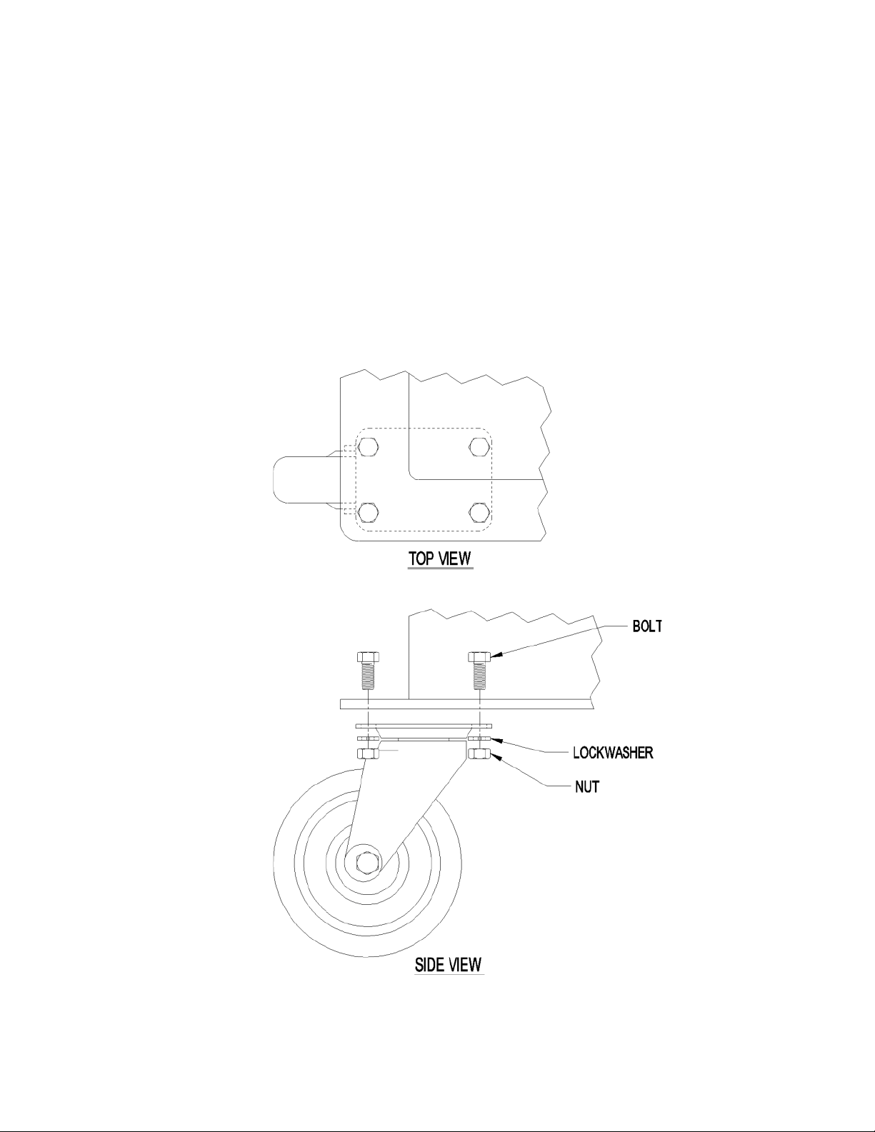
INSTALLATION OF SWIVEL CASTERS:
Locate the 4 swivel casters and bag of hardware that was shipped with the unit.
Have a helper tilt the unit on its bottom edge to install each caster. Insert the bolt from the top, with
the washer and nut on the bottom. Tighten with a 1/2” wrench or socket.
3.
Page 6

Sequence of Operation
This section is a brief overview of the operation of this equipment. The CQC-HD is a machine designed
to perform quick and simple engine coolant changes on larger trucks, tractor-trailers and construction
equipment, forklifts, pickup trucks and automobiles. When properly operated, this quick change can
be accomplished in as little as ten minutes. The following is the normal sequence of operation for a
CQC-HD. Refer to the “Performing a Quick Change” section of this manual for complete instructions
before operating your unit.
PREPARE FOR THE QUICK CHANGE - A vehicle (with engine still warm to hot) is pulled
into the service area and the CQC-HD is positioned. An appropriate amount of new or recycled coolant
is mixed and then pumped into the CQC-HD fill container. Check the vehicle’s operator manual for
cooling system capacity information. Fill the container with the correct amount of coolant.
USE THE DRAIN PUMP - Waste coolant is removed from the vehicle’s overflow container using
the CQC-HD red suction hose and drain pump.
CONNECTING THE
The green fill hose attaches to the neck of the radiator and the black drain hose is attached to the
vehicle’s cooling system through the open end of the upper radiator hose. No hose cutting or tees are
required.
PERFORMING THE QUICK CHANGE – Open the fill valve on the green hose. Leave the
drain valve on the black drain hose closed. Turn the fill pump on. The level in the fill container will
drop, then stop dropping. Close the fill valve and stop the fill pump. Open the vehicle thermostat by
starting the engine and raising the RPMs to running speed for 3-5 minutes. Open the drain and fill
valves and start the fill pump. When the amount of clean coolant drops to the predetermined setting of
the coolant system capacity level, the process is complete.
Note: A special bypass loop is connected to the discharge of the fill pump and prevents the over pressurization of
the engine cooling system. A pre-set pressure relief valve in the bypass loop allows coolant to re-circulate back to
the fill container if the thermostat is closed or partially open. The maximum pressure applied to the engine’s cooling
system is 5 psi.
DISCONNECT THE CQC HD – The CQC-HD is disconnected from the vehicle and the vehicle’s
radiator hose is reattached.
CQC-HDCQC-HD
CQC-HD – Remove the upper radiator hose from the neck of the radiator.
CQC-HDCQC-HD
TOP OFF - The radiator and overflow bottle are filled to proper levels using the green fill hose and
fill pump. The engine is started to check for leaks.
4.
Page 7

CQC-HD Quick Change Process
Color Code Chart
HOSE TYPE PURPOSE
RED Evacuation pump/hose Removes old coolant from radiator and reservoir. Can also be
used to pump out waste coolant from 30 gallon holding tank to
customer supplied 55 gallon drum or tank.
GREEN Fill/Quick change hose In the fill position, fills new coolant into fill container from
customer’s 55 gallon drum of new antifreeze. In the quick-change
position, fills the vehicle’s coolant system with new antifreeze.
BLACK Drain hose Drains old waste coolant from the radiator and engine block into
the 30 gallon waste coolant drum
5.
Page 8

Performing A Quick Change
Following these guidelines will perform a quick change on most vehicles. Due to the variety of diesel
and heavy duty cooling system designs, slight variations of this procedure may be necessary.
PREPARE FOR OPERATION:
1. A quick change works best on a warm vehicle. Allow vehicle to run at an idle for several minutes
prior to initiating a quick change.
WARNING:
!
Wear proper eye and skin protection such as safety glasses and industrial work gloves. Metal
quick-disconnect fittings can become hot to the touch when disconnecting the hoses after
completion of coolant exchange process.
2. Determine the total cooling system capacity of the vehicle. (Refer to the vehicle’s owners manual for
this information). Fill the fill container with a mixture of new or recycled antifreeze and water equal
to the system capacity. If required, add the correct amount of supplemental cooling additive (SCA)
at this time. This could also be mixed in the fill container.
See HELPFUL HINTS for additional information.
3. Place the coolant fill hose, located in the rear of the unit, completely into the
new coolant container and position the 3-way valve, located on the side of the
unit, to the container fill position (see figure 1). Turn the CQC-HD fill pump on
(the switch is located on the front-left side of the unit), until the proper amount
of coolant is pumped into the CQC-HD fill container. Turn the fill pump off and
turn the 3-way valve back to the quick-change position. Return the coolant fill
hose to its hose clip.
Figure 1
NOTE: Most engine manufacturers recommend a mixture of 50% antifreeze
and 50% water. Use distilled or de-mineralized water to prevent scale and
mineral build-up.
4. Check the level in the used coolant drum in the rear of the CQC-HD to verify
that it is not too full to hold another coolant change. See page 9 for instructions on emptying used coolant drum.
5. Pull the warm vehicle into the service area. Set the vehicle’s heater controls to
the highest temperature setting and turn off the heater fan. (This ensures the
exchange of coolant in the heater core)
6. SHUT OFF THE VEHICLE’S ENGINE and open the hood.
7. Verify that the fill valve on the green fill hose and the drain valve on the black
drain hose of the CQC-HD are both in the closed position.
CAUTION:
!
Immediately clean up any spills. Damage to the vehicle and equipment can
result from the corrosiveness of the coolant.
8. Wheel the CQC-HD to the front of the vehicle and plug the electric cord into a
115-volt, 60 Hz, grounded receptacle. Use a 16-gauge (minimum) grounded
extension cord if necessary. A GFI (Ground Fault Interrupter) circuit is recommended.
6.
Page 9

USE OF THE DRAIN PUMP:
CAUTION:
!
The CQC-HD has a high center of gravity and could tip over. Use caution when moving the CQC HD with the fill container full.
!
WARNING:
Large vehicle cooling systems can be under pressure and extremely hot. Allow the vehicle’s
cooling system to cool down and use extreme caution when removing caps and hoses. Consult
the vehicle manufacturer for recommended procedure on removing the radiator cap.
1. Squeeze the vehicle’s upper radiator hose to determine the amount of pressure in the system. If the
hose is hot and hard, allow the cooling system to cool down before proceeding.
2. Carefully remove the cap of the vehicle’s overflow bottle. In many cooling systems there is one cap
for both the radiator and the overflow container. Using a clamp or locking pliers, carefully pinch the
flexible overflow tube closed to prevent fluid leakage during coolant exchange.
3. Insert the plastic wand on the red suction hose into the overflow bottle. Turn on the CQC-HD
drain pump (the switch is located on the front right side of the unit) and remove the liquid from the
overflow container. Turn off the drain pump and replace the cap to the overflow bottle.
Hint: If the overflow bottle contains sludge, loosen it with water sprayed with
a hose.
4. Remove the vehicle’s radiator cap. Insert the plastic wand from the red
suction hose into the radiator (see figure 2). Turn on the CQC-HD drain pump
(the switch that is located on the right-front side of the unit) and remove liquid
from the radiator until the level is below the upper radiator hose. Turn off the
drain pump. Replace the radiator cap.
Note: If the radiator has no cap, locate the radiator drain. Open the drain valve
and collect liquid from the radiator in a drain receptacle until the level is below
the upper radiator hose and level of the thermostat. You may be able to utilize
the red evacuation pump/wand to assist in the drain process. Place the plastic wand on the end of the
petcock valve. Turn the petcock drain valve and the evacuation pump on. After completion of this
step, close the radiator drain valve.
CAUTION:
!
Do not remove too much liquid from the radiator. Allowing air to enter the lower radiator hose
can result in damage to the vehicle’s engine.
Figure 2
!
CAUTION:
Never allow the CQC-HD pumps to operate without liquid. Running the pumps dry will cause
premature wear or damage to the pump and is not covered under warranty.
7.
Page 10

Connecting the CQC-HD to the Vehicle
HINT: It may save time on the coolant exchange process if you attach the CQC-HD drain and fill
hose connections to the vehicle’s radiator while the engine is cold. Keep both valves on the hoses
closed at this point.
CAUTION:
!
Prior to connecting the CQC-HD to the vehicle, check for proper operation of the fill pump.
With the three-way valve on the side of the CQC-HD cabinet set to “quick change” and the
valve on the end of the green fill hose closed, turn on the CQC-HD fill pump (switch located
on the front left side of the cabinet). Check to see that the pump is pumping liquid through
the bypass loop (clear hose) into the fill container. If so, proceed with attachment to the
vehicle. If not, see the maintenance section for maintenance to pump and/or check valve.
1. Loosen the hose clamp that holds the upper radiator hose to the neck of the radiator. Use a nutdriver, screwdriver, or hose clamp pliers (depending on the type of clamp)
to loosen the clamp.
2. Remove the upper radiator hose from the neck of the vehicle’s radiator
(Figure 3). Be careful not to damage the radiator inlet or hose while
removing.
Figure 3
3. Determine the proper flex-hose size for the vehicle’s radiator. Choose the
correct quick disconnect/step adapter (hard gray plastic) and couple the
flex hose to the step adapter. Attach the black drain hose from the CQCHD to the removed, open end of the upper radiator hose by inserting its
hard plastic step adapter into the upper radiator hose. With a hose
clamp, seal the upper radiator hose tightly to the best fit step on the
step adapter.
Figure 4
HINT: In some cases, the size difference between the upper radiator hose and the step adapter
may seem too large. It is okay to tighten down the hose clamp to seal up to a 1/4 inch gap.
A worm gear-type clamp tightened with a nut driver works best.
4. Attach the “best fit” flexible hose adapter to the neck of the radiator’s inlet and secure it tightly
using the supplied hose clamp. Be careful not to damage the radiator’s inlet.
5. Determine the proper flex-hose size for the vehicle’s radiator. Choose the correct quick disconnect/
step adapter (hard gray plastic) and couple the flex hose to the step adapter. Attach the green fill
hose from the CQC-HD by inserting its hard plastic step adapter into the open end of the flexible
hose adapter. With a hose clamp, seal the flexible hose adapter tightly to the “best fit” step on the
hard plastic step adapter. Connections should look similar to figure 4.
!
CAUTION:
Check and assure that all hoses, rags, tools, or other objects will be clear from moving parts of
the vehicle.
8.
Page 11

Coolant Exchange OperationCoolant Exchange Operation
Coolant Exchange Operation
Coolant Exchange OperationCoolant Exchange Operation
WARNING:
!
Keep clothing, hair, hands, etc. away from all moving parts of the vehicle.
CAUTION:
!
Continuous monitoring of the quick-change process is required. Leaving the vehicle unattended
while operating this equipment can result in damage to the engine, vehicle, and/or equipment.
1. Verify that the 3-way valve located on the side of the unit is in the quickchange position (Figure 5).
2. Open the fill valve on the green fill hose and turn the fill pump on. The level
in the fill container will begin to drop, then stop. Close the fill valve on the
green fill hose and turn the pump off. Keep the drain valve on the
black drain hose closed at this time.
3. Start the engine of the vehicle.
4. The coolant change can occur only if the vehicle’s thermostat is open. To get
the vehicle up to normal operating temperature, it will be necessary to raise the
RPMs of the engine to running speed. Do this for approximately 3 to 5 minutes, or until engine reaches normal operating temperature.
5. Open both, the drain hose valve on the black drain hose and the fill valve on
the green fill hose, turn on the fill pump. Watch the level in the fill container
(Fig. 6). The level in the fill container should drop and used coolant should
drain into the waste coolant drum.
If new coolant level does NOT drop or stops dropping, close both valves and stop fill pump.
Repeat step 4. Continue steps 4 and 5 until level in the fill container reaches approximately 2 gallons.
6. Close the fill valve on the green fill hose and turn off the fill pump when the two gallons remain
in the fill container
7. Allow the engine to run for 10 seconds after closing the fill valve; then turn the engine off. This
lowers the coolant level in the radiator to help prevent coolant spilling when re-attaching the
upper radiator hose.
Figure 5
Figure 6
CAUTION:
!
Failure to turn vehicle’s engine off ten seconds after closing fill valve can result in damage
to the vehicle.
9.
Page 12

!
CAUTION:
Never allow the fill pump to operate without liquid. Running the pump dry will cause premature
wear or damage to the pump and is not covered under warranty.
8. It is highly sugested that the operator wear industrial work gloves when disconnecting the CQC-HD
from the vehicle. Close the drain valve on the black drain hose after the engine is turned off.
9. Disconnect the CQC-HD from the vehicle. Carefully reconnect the upper radiator hose to the
radiator and securely clamp.
10. Remove the vehicle’s radiator cap and/or overflow bottle cap. Remove clamp from the flexible
overflow tube. Top off the radiator and overflow bottle using the remaining coolant in the fill
container. Turn the fill pump on, and while holding the green fill hose over
the radiator’s opening, slowly open the fill valve to allow the top off coolant
to flow. Also, fill the vehicle’s coolant overflow bottle to the proper level.
Return both caps and secure.
11. Start the engine of the vehicle and check for leaks.
Draining the Waste Coolant Drum
1. Remove the red hose from the waste coolant drum (located in the back of
the machine) and place it into a receiving container (Figure 8).
2. Insert the red drain hose (wand attachment) into the opening on the waste
coolant drum until it reaches the bottom (Figure 9).
3. Turn on the drain pump (located on the front right side of the unit).
4. Allow the pump to run until all liquid is removed from the waste coolant drum.
5. Turn off the drain pump and return the red hoses to their original positions.
CAUTION:
!
Never allow the pump to operate without liquid. Running the pump dry will cause premature
wear or damage the pump and is not covered under warranty.
Figure 8
Figure 9
10.
Page 13

PerPer
forfor
Per
PerPer
ming A Quick-Change thrming A Quick-Change thr
for
ming A Quick-Change thr
forfor
ming A Quick-Change thrming A Quick-Change thr
ough the Heater Hoseough the Heater Hose
ough the Heater Hose
ough the Heater Hoseough the Heater Hose
Many heavy-duty diesel engines have heater hoses running to and from the engine block below the
thermostat location through a fuel pre-heat exchanger and then on to a cab heater on the firewall. On
many diesel engines these hoses are more accessible than the upper radiator hoses. On this type of
engine configuration, it is possible to conduct the coolant exchange process with the CQ-HD through
these heater hoses. The advantage to this method is that you do not have to have the engine running
to complete the coolant exchange process. Listed below are the steps to conduct a coolant exchange
through the heater hose.
Prepare for Operation
1. Repeat steps 2-4 listed on page 6
2. Pull the vehicle into the service area, in this case it does not have to be warm.
3. Repeat steps 6-8 listed on page 6
4. Locate the heater line between the engine block and the fuel pre-heater
Connecting the CQC-HD to the Heater Hose
6. Loosen the hose clamp that holds the most accessible heater hose (a high point is suggested to
minimize spillage) to its inlet. Use a nut driver, screwdriver or hose pliers (depending upon clamp
type) to loosen the clamp.
7. Remove the heater hose from the connection. Be careful not to damage the connection or hose
while removing.
8. Attach the black drain hose from the CQC-HD to the removed open end of the heater hose by inserting the best fit quick disconnect/step adapter coupling into the heater hose. Using a hose clamp,
seal the heater hose tightly with the “best fit” step on the quick disconnect/step adapter.
HINT: In some cases the size difference between the heater hose and quick disconnect step adapter
may seem too large. It is okay to tighten down the hose clamp to seal up the ¼ inch gap. A worm
gear-type clamp tightened with a nut driver works best.
9. Attach the “best fit” flexible hose adapter to the connection where the heater hose was removed and
secure it tightly using the supplied hose clamp. Be careful not to damage the connection.
10. Attach the green hose from the CQC-HD by inserting the quick disconnect/step adapter into the
open end of the flexible hose adapter. With a hose clamp, seal the flexible hose adapter tightly to
the “best fit” step on the quick disconnect /step adapter.
11.
Page 14

Coolant Exchange Operations for Heater Hose
11. Verify that the three way valve located on the side of the CQC-HD is in the quick-change position
12. Open the fill valve on the green hose and turn the fill pump on. The vehicle’s engine does not
have to be turned on.
13. Open the drain valve on the black hose. The new coolant will fill the engine block and the old
coolant will drain into the 30-gallon waste tank in the back of the CQC-HD.
14. Fill the engine block until about 60% of the coolant in the fill container is gone (40% remaining)
and then turn off the fill valve on the green hose and turn the fill pump off.
NOTE: Actual ratios of engine coolant capacity to radiator capacity can vary.
15. Turn off the drain valve on the black hose.
16. Disconnect the CQC-HD from the vehicle. Carefully reconnect the heater hose to its original position and securely clamp.
17. Remove the vehicle’s radiator cap and/or overflow bottle cap. Insert the plastic wand on the red
suction hose into the overflow bottle. Turn on the CQC-HD drain pump (the switch is located on
the front right side of the unit) and remove the liquid from the overflow container. Turn off the
drain pump.
Hint: If the overflow bottle contains sludge, loosen it with water sprayed with a hose.
18. Drain the coolant from the radiator by opening the drain valve and collecting the coolant in a
receptacle. You may be able to utilize the red evacuation pump/wand to assist in the drain
process. Place the plastic wand on the end of the petcock valve. Turn the petcock drain valve
and the evacuation pump on. After completion of this step, close the radiator drain valve.
19. Fill the radiator and the overflow bottle using the remaining coolant in the CQC-HD’s upper fill
bucket. Turn the fill pump on, and while holding the green fill hose over the radiator’s opening,
slowly open the fill valve to allow the top off coolant to flow. Also, fill the vehicle’s coolant
overflow bottle to the proper level. Return both caps and secure.
20. Start the engine of the vehicle, allow it to run for a few minutes, then check for leaks.
12.
Page 15

Maintenance Schedule
EVERY USE:
CLEANUP ANY SPILLS – Antifreeze/coolants can be corrosive to the unit’s painted finish. Immediately
wipe, rinse and dry any spills thoroughly.
AS REQUIRED:
FLUSH THE DRAIN PUMP – Dirt and grit from waste coolant can cause premature wear on the drain
pump’s impeller. Periodically flush the pump by pumping 5 gallons of cool, clean water through the
red hose.
REPLACE PUMP IMPELLER – Replace impeller if loss of pump performance is noticed due to pump
being run dry, wear, or damage from foreign objects.
1. Disconnect power.
2. Remove cover plate from the pump head
(held in place with four phillip’s head screws).
3. Pull out old impeller.
4. Lubricate the new impeller with petroleum jelly.
5. Push the impeller onto the motor shaft at the same time twisting in a clockwise direction. This will
bend the blades in the direction for proper rotation.
6. Replace the pump’s cover using a new gasket. Tighten all screws evenly and snugly. Do not over
tighten the screws.
PRESSURE RELIEF VALVE – Replace the pressure relief valve if it appears to be stuck in an open or
closed position.
Warranty
Finish Thompson, Inc (manufacturer) warrants this product to be free of defects in materials and workmanship for a period
of 1 year from date of purchase by original purchaser. If a warranted defect, which is determined by manufacturer’s
inspection, occurs within this period, it will be repaired or replaced at the manufacturer’s option, provided (1) the product
is submitted with proof of purchase date and (2) transportation charges are prepaid to the manufacturer. Liability under this
warranty is expressly limited to repairing or replacing the product of parts thereof and is in lieu of any other warranties, either
expressed or implied. This warranty does apply only to normal wear of the product or components. This warranty does not
apply to products or parts broken due to, in whole or in part, accident, overload, abuse, chemical attack, tampering, or
alteration. The manufacturer accepts no responsibility for product damage or personal injuries sustained when the product
is modified in any way. If this warranty does not apply, the purchaser shall bear all cost for labor, material and transportation.
Manufacturer shall not be liable for incidental or consequential damages including, but not limited to process down time,
transportation costs, costs associated with replacement or substitution products, labor costs, product installation or
removal costs, or loss of profit. In any and all events, manufacturer’s liability shall not exceed the purchase price of the
product and/or accessories.
TECHNICAL SERVICE HOTLINE: 800-888-3743
13.
Page 16

Helpful Hints
• It is recommended that during initial operation the drain and fill pumps be primed. To do this, pour
approximately one gallon of water into the upper fill container.
FILL PUMP - place the valve in “container fill” position and turn on fill pump until flow is observed
through the bypass loop. Turn off the fill pump.
EVACUATION PUMP - place wand in fill container and turn on evacuation pump. Water flows into
waste coolant drum. Turn off evacuation pump when fill container is empty.
• The CQC-HD was shipped with four spare impellers. Keep these in a known location for future use.
• Do not let the pump run dry for more than 20 seconds. Damage to the flexible impeller can occur if
run dry for a longer period.
• Do not suck up undiluted “sludge” from the radiator overflow bottle. Use a hose to loosen and dilute
the “sludge” with water first.
• Do not allow the operator to leave the machine unattended during the process.
• Vehicles with pressurized overflow bottles hook up the same way as non-pressurized designs.
• If steam is noticed coming out of the 30-gallon drum during the process and no new coolant is
flowing in, turn the vehicle off and leave both the fill and drain valves open and the fill pump
on. Wait a few minutes until the level in the fill container starts to drop, then start the vehicle and
complete the process normally.
• If you notice fluid draining from the radiator reservoir bypass, it means that your thermostat has not
opened sufficiently. Shut off the fill pump, fill and drain valves, and rev the engine for 3 to 4
minutes to open the thermostat. Start the fill pump, open the fill and drain valves and complete the
process as you would normally.
• Fill container can be filled in any one of several methods. Use the coolant fill hose to pump from a
55-gallon drum, buckets, or single gallon containers. A mixture of antifreeze coolant and water can
be made up into a clean 55-gallon drum or concentrated antifreeze can be pumped into the fill
container followed by the appropriate amount of clean water. Be sure to add the appropriate amount
of SCA’s (Supplemental Coolant Additives) if required. Fill container has a large 3” threaded opening
at the top that can be utilized to manually pour fluid into the container.
• In cold winter months, mixing warm water with antifreeze can help the coolant change faster by
helping to keep the thermostat open.
• Keep an eye on the temperature gauge to make sure the vehicle is not overheating
14.
Page 17

Helpful Hints (continued)
• It is possible to connect the drain and fill hoses on the CQC-HD to the engine while it is
cold. It is important to keep both valves on the hoses closed at this time.
(see steps 1 - 5 on page 8)
• It is possible to fill an empty cooling system (after water pump replacement, engine overhaul, radia-
tor replacement, etc.) by using the heater hose quick change procedures (see page 11).
CAUTION:
!
Do not allow the liquid temperature in the fill container to exceed 130ºF/55ºC.
• If the process is not working, the vehicle may have a defective thermostat. Abort the process.
Remove and test the thermostat or refer the customer to a service facility capable of thermostat
replacement.
15.
Page 18

Common Spare Parts
Coolant Quick Changer:
7
8
1
4
3
14
11
2
5
6
Item Description Part Number
1 On/Off Switches J101704
2 Fill Container M102175
3 1st Step Adapter (up to hose sizes 2-3/4”) M102169
4 Ball Valve J101629
5 Plastic Wand for RED Hose M101271
6 RED Pump Hose M101270
7 GREEN Fill Hose M101269
8 BLACK Drain Hose M101268
9* Pump Impeller Kit J101775
10* Evacuation Pump & Motor Assembly A101591
11 Bypass Check Valve J103686
12* Fill/Quick Change Pump and Motor Assembly A103128
13* 2-Way Ball Valve J101629
14 2nd Step Adapter (up to hose sizes 1-3/4”) M101273
15* Quick Disconnect Coupling J103745
* Items not shown on drawing
16.
Page 19

Tech Service 1-800-888-3743
Literature ID No. FT00-794A, 12/03
 Loading...