

Page 1
OPERATION
&
iNSTALLATION
MANUAL
pART nO. J101747, version 3.2, rev. 3
1
Page 2

Introduction
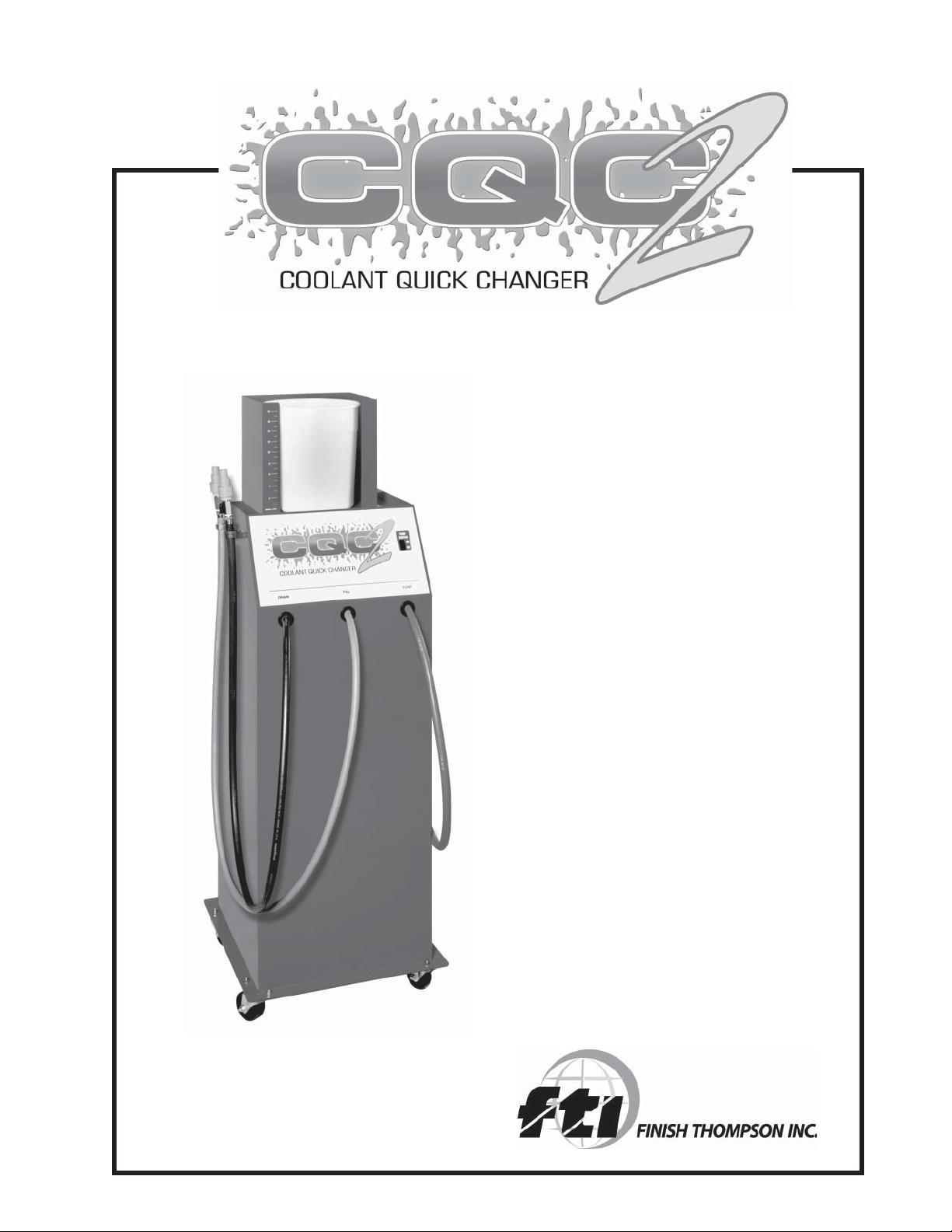
DESCRIPTION:
The Coolant Quick Changer is a time saving members of FTI’s family of coolant handling equipment. This
portable unit safely drains and refills automotive engine cooling systems in a portion of the time it takes for
conventional methods. When properly operated, this unit induces no air or pressure into the engine’s cooling
system. No hose cutting or tee is required - gravity and the engine’s own water pump perform the service.
YOUR RESPONSIBILITY:
The user of a CQC2 is solely responsible for all environmental and safety concerns, or laws pertaining to the
use and disposal of antifreeze/coolant handled or produced by this equipment.
Do your part for the environment. Recover, recycle when possible, and dispose of wastes in a proper manner.
Table of Contents
Introduction .................................................................................................................................................. 2
Safety Precautions ...................................................................................................................................... 3
Assembly ..................................................................................................................................................... 4
Sequence of Operations .............................................................................................................................. 5
Performing a Quick Change ......................................................................................................................... 6
Use of Evacuation Pump ...................................................................................................................... 6-7
Attach CQC2 to Vehicle ......................................................................................................................... 7
Attach CQC2 - Special Cooling Systems .............................................................................................. 7
Performing A Quick Change .................................................................................................................. 8
Draining the Waste Coolant Drum ......................................................................................................... 9
Maintenance Schedule ........................................................................................................................ 9-10
Helpful Hints ............................................................................................................................................... 10
Common Spare Parts ................................................................................................................................. 11
2
Page 3

Safety Precautions
WARNING:
FAILURE TO FOLLOW THESE PRECAUTIONS CAN RESULT IN SERIOUS INJURY OR
DEATH.
· Read and understand the operation manual completely before operating this unit.
· Always wear proper eye and skin protection when operating and maintaining this equipment.
· Hazardous voltages present. Use only with a grounded electrical outlet and grounded extension cords. Do
not remove the ground prong from the plug.
· Take precautions to keep clothing, hair, hands, hoses, etc. away from all moving parts on the vehicle.
· Automotive cooling systems can be under pressure and extremely hot. Allow the cooling system to cool
down and use extreme caution when removing caps and hoses.
· Antifreeze/coolants are poisonous to people and animals and are also corrosive. Clean up any spills
immediately.
CAUTION:
FAILURE TO FOLLOW THE PROCEDURES/ PRECAUTIONS AS OUTLINED IN THE OPERATION MANUAL
CAN RESULT IN DAMAGE TO THE ENGINE, VEHICLE OR EQUIPMENT AND WILL NOT BE SUPPORTED
OR COVERED UNDER WARRANTY.
· Do not allow waste coolant drum to overflow. Immediately clean up any coolant or reinhibitor spills. Damage
to the vehicle and equipment can result from the corrosiveness of coolants and reinhibitors.
· Continuous monitoring of the Quick Change process is required. Leaving the vehicle unattended while
operating this equipment can result in damage to the engine, vehicle, and/or equipment.
3
Page 4
Assembly
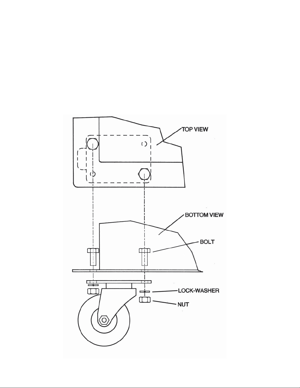
INSTALLATION OF SWIVEL CASTERS:
Locate the 4 swivel casters and bag of hardware that was shipped in the fill bucket on the top of the unit. Verify that
the hardware bag contains 8 bolts, 8 lock-washers, and 8 nuts.
Have a helper tilt the unit on its bottom edge to install each caster. Insert the bolt from the top, with the washer and
nut on the bottom. Tighten with a 1/2” wrench or socket.
4
Page 5

Sequence of Operation
The CQC2 is a device designed to perform quick
and simple engine coolant changes on automobiles and light trucks. When properly operated,
this quick change can be accomplished in as
little as ten minutes. The following is the normal
sequence of operation for a CQC. Refer to the
“Performing A Quick Change” section of this
manual for complete instructions before operating your unit.
PREPARE FOR THE QUICK CHANGE - A
vehicle is pulled into the service area and the
CQC is positioned. An appropriate amount of
new or recycled coolant is mixed in the CQC fill
bucket.
USE THE EVACUATION PUMP - Waste coolant
is removed from the vehicle’s radiator and
overflow bottle using the CQC2 RED suction
hose.
ATTACH THE CQC2 - The GREEN fill hose and
BLACK drain hose are attached to the vehicle’s
cooling system through a removed upper
radiator hose. No hose cutting or tees are
required.
PERFORM THE QUICK CHANGE - While the drain valve on the BLACK drain hose is closed, the Fill Valve on the
GREEN fill hose is opened and the vehicle’s engine is started. The upper house drain valve is opened, and the level in
the fill bucket will drop as the new coolant displaces the waste coolant. The waste coolant drains through the BLACK
drain hose and into the Waste Coolant Drum in the rear of the unit. When only two quarts of new coolant remain in the
CQC2 new coolant bucket, the fill and drain valves are closed, and the vehicle’s engine is turned off.
DISCONNECT THE CQC2 - The CQC2 is removed from the vehicle and the vehicle’s radiator hose is reattached.
TOP OFF - The radiator and overflow bottle are filled to proper levels using the GREEN fill hose. The engine is started
to check for leaks.
5
Page 6

Performing A Quick Change
Following these procedural guidelines will perform a Quick Change on most vehicles. Due to the variety of automobile, SUV and light truck cooling system designs, slight variations of this procedure may be necessary.
PREPARE FOR OPERATION:
1. Pull the vehicle into the service area. Set the vehicle’s heater controls to the highest temperature setting and
turn off the heater fan.
2. SHUT OFF THE VEHICLE’S ENGINE and raise the hood.
3. Verify that the fill valve on the green fill hose and the drain valve on the black drain hose of the CQC2 are both
in the CLOSED position.
WARNING: Wear proper eye and skin protection such as safety glasses and gloves.
4. Determine the total cooling system capacity of the vehicle. Prepare a mixture of new or recycled antifreeze
and water equal to the system capacity. Pour the mixture into the fill bucket. Place the lid onto the fill bucket.
NOTE: Most engine manufacturer’s recommend a mixture of 50% antifreeze and 50% water. Use distilled or
demineralized water to prevent scale and mineral build-up.
HINT: In cold winter months, mixing warm water with the antifreeze can help the coolant change occur more
quickly by helping to keep the engine’s thermostat open.
5. Check the level in the used coolant rum in the rear of the CQC2 to
verify that it is not too full to hold another coolant change.
CAUTION: Immediately clean up any spills. Damage to the
vehicle and equipment can result from the corrosiveness of the
coolant.
6. Wheel the CQC2 to the front of the vehicle and plug the electric
cord into a 115 volt, 60 Hz, grounded receptacle. Use a 16 gauge
(minimum) grounded extention cord if necessary.
NOTE: The CQC2 relies on gavity to fill the vehicle’s cooling system.
The TOP of the vehicle’s radiator must be LOWER than the BOTTOM
of the Fill Bucket on the CQC2 for the coolant change to occur.
USE OF THE EVACUATION PUMP:
WARNING: Automotive cooling systems can be under pressure and extremely hot. Allow the vehicle’s cooling
system to cool down and use extreme caution when removing caps and hoses. Consult the vehicle manufacturer for
recommended procedure on removing the radiator cap.
1. Squeeze the vehicle’s upper radiator hose to determine the amount of pressure in the system. If the hose is hot
and hard, allow the cooling system to cool down before proceeding.
2. Carefully remove the vehicle’s radiator cap.
3. Insert the Plastic Wand on the RED suction hose into the radiator. Turn on the CQC2 evacuation pump (the
6
Page 7

CAUTION: Never allow the evacuation pump to operate without liquid. Running the pump dry will cause
premature wear or damage to the pump and is not covered under warranty.
4. Locate the vehicle’s coolant overflow bottle and remove its cap. Insert the plastic wand on RED suction hose
into the overflow bottle, turn on the evacuation pump, and remove as much liquid as possible. Turn off the
pump and return the RED suction hose to its hose clip. Replace the cap on the overflow bottle.
HINT: If the overflow bottle contains sludge, loosen it with water sprayed from a hose.
ATTACH THE CQC2 TO THE VEHICLE - CONVENTIONAL COOLING SYSTEMS:
1. Loosen the hose clamp that holds the UPPER radiator hose to the radiator.
Use a nut-driver, screwdriver, or hose clamp pliers (depending on the type
of clamp) to loosen the clamp.
2. Pull loose and remove the UPPER radiator hose from the vehicle’s
radiator. Be careful not to damage the radiator inlet or hose while
removing.
3. Attach the BLACK drain hose from the CQC2 to the removed,
open end of the UPPER radiator hose by inserting its step adapter
into the UPPER radiator hose. With a hose clamp, seal the UPPER
radiator hose tightly to the “best fit” step on the step adapter.
HINT: In some cases, the size difference between the UPPER
radiator hose and the step adapter may seem too large. It is OK
to tighten down the hose clamp to seal up to a 1/4" gap. A “wormgear” type clamp tightened with a nut driver works best.
4. Attach the “best fit” flexible hose adapter to the radiator’s inlet and
secure it tightly using the supplied hose clamp. Be careful not to
damage the radiator’s inlet.
5. Attach the GREEN Fill Hose from the CQC2 by inserting its step
adapter into the open end of the flexible hose adapter. With a
hose clamp, seal the flexible hose adapter tightly to the “best fit”
step on the step adapter.
CAUTION: Check and assure that all hoses, rags, tools, or other objects will be clear from moving parts of the
vehicle.
ATTACH THE CQC2 TO THE VEHICLE - SPECIAL COOLING SYSTEMS:
HINT: Some vehicles with non-conventional cooling systems require a different procedure for attaching the
CQC2. Some examples are:
• Mid or rear engine vehicles with the radiator in the front of the vehicle.
• Radiators that do not allow access to the upper radiator hose.
• Pressurized overflow systems where the overflow bottle is capped, not the radiator.
1. Loosen the hose clamp that holds the UPPER radiator hose to the thermostat housing on the engine. Use a
nut-driver, screwdriver, or hose clamp pliers (depending on the type of clamp) to loosen the clamp.
2. Pull loose and remove the UPPER radiator hose from the vehicle’s thermostat housing inlet. There may be
liquid in the hose - place a supply of rags under the hose to catch any spilled coolant. Be careful not to damage radiator hose while removing.
3. Attach the GREEN fill hose from the CQC2 to the removed, open end of the UPPER radiator hose by inserting
its Step Adapter into the UPPER radiator hose. With a hose clamp, seal the UPPER radiator hose tightly to the
“best fit” step on the step adapter.
7
Page 8

HINT: In some cases, the size difference between the UPPER radiator hose and the step adapter may seem too
large. It is OK to tighten down the hose clamp to seal up to a 1/4" gap. A “worm-gear” type clamp tightened with a
nut driver works best.
4. Attach the “best fit” flexible hose adapter to the thermostat housing’s inlet and secure it tightly using the sup
plied hose clamp.
5. Attach the BLACK drain hose from the CQC2 by inserting its step adapter into the open end of the flexible
hose adapter. With a hose clamp, seal the flexible hose adapter tightly to the “best fit” step on the step adapter.
CAUTION: Check and assure that all hoses, rags, tools, or other objects will be clear from moving parts of the
PERFORMING THE QUICK CHANGE:
WARNING: Keep clothing, hair, hands, etc. away from all moving parts of the vehicle.
CAUTION: Continuous monitoring of the quick change process is required.
Leaving the vehicle unattended while operating this equipment can result in
damage to the engine, vehicle, and/or equipment.
1. OPEN the Fill Valve on the GREEN fill hose. The level in the fill bucket
will begin to drop, then stop. Keep the drain valve on the black drain hose
closed at this time.
2. Start the engine of the vehicle.
3. OPEN the drain valve on the black drain hose. Watch the level in the fill bucket. If the level does not drop, or
stops dropping, CLOSE the drain valve. After approximately 30 to 60 seconds, RE-OPEN the drain valve.
Repeat this procedure until two quarts remain in the fill bucket.
NOTE: Opening and closing the drain valve as described will protect vehicles
with the thermostat located ahead of the water pump (“reverse flow” cooling
systems). This procedure prevents the old coolant from being pumped out of the
engine block prematurely when the new coolant is restricted by a closed thermostat.
HINT: The coolant change can occur only if the vehicle’s thermostat is open.
To help get the vehicle up to normal operating temperature, it may be neces
sary to raise the RPM’s of the engine to warm it up before the level in the Fill
Bucket will continue to drop.
4. CLOSE the fill valve on the green fill hose.
5. Allow the engine to run for 10 seconds after closing the fill valve, then TURN THE
ENGINE OFF. This lowers the coolant level in the radiator to help prevent coolant
spilling when reattaching the UPPER radiator hose.
CAUTION: Failure to turn vehicles engine off ten seconds after closing Fill Valve
can result in damage to the vehicle.
6. CLOSE the Drain Valve on the BLACK Drain Hose.
7. Remove the CQC2 from the vehicle. Reconnect the UPPER radiator hose to the radiator (or the thermostat
housing for “Special” cooling systems) and clamp securely.
8. Remove the vehicle’s radiator cap and top off the radiator using the remaining coolant in the fill bucket. While
holding the GREEN fill hose over the radiator’s opening, SLOWLY open the fill valve to allow the top off coolant
to flow. Also, open the vehicle’s coolant overflow bottle and fill to the proper level. Return both caps and
secure.
9. Start the engine of the vehicle and check for leaks.
8
Page 9

DRAINING THE WASTE COOLANT DRUM:
1. Remove the BLACK hose from the large opening of the waste
coolant drum (located in the back of the machine) and place it into a
receiving container.
2. Insert the wand from the RED hose into the large opening on the
waste coolant drum until it reaches the bottom.
3. Turn ON the evacuation pump (switch located on the front bevel of
the unit).
4. Allow the pump to run until all liquid is removed from the waste
coolant drum.
5. Turn OFF the evacuation pump and return BLACK and RED hoses
to their original positions.
CAUTION: Never allow the pump to operate without liquid. Running
the pump dry will cause premature wear or damage the pump and is
not covered under warranty.
MAINTENANCE SCHEDULE
EVERY USE:
CLEANUP ANY SPILLS - Antifreeze/coolants can be corrosive to the unit’s painted finish. Thoroughly wipe, rinse and
dry any spills immediately.
AS REQUIRED:
FLUSH THE EVACUATION PUMP - Dirt and grit from waste coolant can cause premature wear on the Evacuation
Pump’s impeller. Periodically flush the pump by pumping 5 gallons of cool, clean water through the RED hose.
REPLACE PUMP IMPELLER - If loss of pump performance is noticed due to pump being run dry, wear or damage
from foreign objects, replace impeller.
1. Disconnect power, Remove the CQC2’s rear panel.
2. Remove cover plage from the pump head (held in place with four Phillips head screws).
3. Pull out old impeller.
4. Lubricate the new impeller with petroleum jelly.
9
Page 10

MAINTENANCE SCHEDULE (continued)
5. Push the impeller onto the motor shaft and at the same time twist in a clockwise direction. This will bend the
blades in the direction for proper operation.
6. Replace the pump’s cover using a new gasket, tightening all screws evenly and snugly. Do not over tighten the
screws. Replace the rear panel on the CQC2.
WARRANTY
Finish Thompson, Inc (manufacturer) warrants this product to be free of defects in materials and workmanship for a period of 1
year from date of purchase by original purchaser. If a warranted defect, which is determined by manufacturer’s inspection,
occurs within this period, it will be repaired or replaced at the manufacturer’s option, provided (1) the product is submitted with
proof of purchase date and (2) transportation charges are prepaid to the manufacturer. Liability under this warranty is expressly
limited to repairing or replacing the product of parts thereof and is in lieu of any other warranties, either expressed or implied.
This warranty does apply only to normal wear of the product or components. This warranty does not apply to products or parts
broken due to, in whole or in part, accident, overload, abuse, chemical attack, tampering, or alteration. The manufacturer accepts
no responsibility for product damage or personal injuries sustained when the product is modified in any way. If this warranty
does not apply, the purchaser shall bear all cost for labor, material and transportation.
Manufacturer shall not be liable for incidental or consequential damages including, but not limited to process down time,
transportation costs, costs associated with replacement or substitution products, labor costs, product installation or removal
costs, or loss of profit. In any and all events, manufacturer’s liability shall not exceed the purchase price of the product and/or
accessories.
HELPFUL HINTS
TECHNICAL SERVICE HOT LINE: 800-888-3743
The CQC2 shipped with two spare impellers. Keep these in a known location for future use.
• Do not let the pump run dry for more than 20 seconds. Damage to the flexible impeller can occur if run dry for
a longer period.
• Do not suck up undiluted “muck” from the radiator overflow bottle. Use a hose to loosen and dilute the “muck”
with water first.
• Do not allow the operator to leave the machine unattended during the process.
• Vehicles with pressurized overflow bottles hook up the same way as non-pressurized designs.
• If you notice steam coming out of the 15 gallon drum during the process and no new coolant is flowing in, turn
the vehicle off and leave both the fill valve and the drain valves open. Wait a few minutes until the level in the
fill bucket starts to drop, then start the vehicle and complete the process normally.
• Inlet thermostat designs (where the thermostat is located before the water pump) can cause the process to
take longer than normal. On inlet thermostat designs, use hot water/antifreeze in the fill bucket if possible.
This can help to keep the thermostat open and speed up the process.
CAUTION: Do not allow the liquid temperature in the fill bucket to exceed 130oF(55oC).
• If the process is not working, the vehicle may have a defective thermostat. Abort the process. Remove and
test the thermostat or refer the customer to a service facility capable of thermostat replacements.
• If the vehicle has coolant bleed screws, bleed any air that is potentially trapped after the coolant exchange is
complete.
• If the machine is not going to be used for an extended period (more than a couple of weeks), lubricate the
pump impeller with petroleum jelly before storing.
10
Page 11

COMMON SPARE PARTS
COOLANT QUICK CHANGER2
Item Description Part Number
1 On/off switch J101704
2 Fill bucket M101267
3 Step adapter M101273
4 Ball valve J101629
5 Plastic wand for red hose M101271
6 Red pump hose M101270
7 Black drain hose M101268
8 Green fill hose M101269
9* Pump Impeller Kit A102100
10* Evacuation Pump & Motor Ass’y. A101591
* Items are not shown on drawing.
11
Page 12

SERVICE 1-800-888-3743
Literature ID No. FT01-839, 12/03
12
 Loading...