

Page 1
7
s
COOLANT RECYCLING SYSTEM
BE-55C
Instruction Manual
For unit
Serial # number
0660A96
or newer
Version
July
2014
Page 2
BE-55C Instruction Manual
~ Introduction ~
Congratulations on your purchase of the BE-55C Coolant Recycling System. The BE-55C is designed
to recycle used ethylene or propylene glycol-based engine coolants utilizing vacuum distillation
technology (the same process used in the manufacture of new anti-freeze). The recycled product
meets or exceeds original equipment specifications. The process is completely automatic, requiring
minimal operator involvement. When properly operated and maintained, the BE-55C can provide years
of trouble-free service and reduce new antifreeze purchases and waste disposal. Recycling is also
good for the environment.
~ Table of Contents ~
RECORD YOUR SERIAL NUMBER HERE: ________________________________
Safety Precautions 2
Parts Description and Terminology 3
Start-Up and Installation 4
Supplied Parts and Accessories 4
Choosing a Location 4
Fill and Drain Assembly 5
Pressure Relief Valve 5
Air Connections 5
Electrical Connections 6
Priming the Circulation Pump 6
Sequence of Operations 7
Operating the BE-55C 8-9
Reinhibitor Information 10
Maintenance Schedule 11
Trouble Shooting Guide 14 - 34
Specifications 35
Common Spare Parts 35
Parts Location Diagram 36
Hose Layout Diagram 37
Electrical Schematic 38
Warranty 39
1
Page 3
~ Safety Precautions ~
WARNING: READ THIS MANUAL COMPLETELY BEFORE
INSTALLING AND OPERATING THIS UNIT. FAILURE TO FOLLOW
THESE PRECAUTIONS CAN RESULT IN SERIOUS INJURY OR
DEATH.
A QUALIFIED ELECTRICIAN SHOULD PERFORM ELECTRICAL WIRING.
WEAR PROPER EYE AND SKIN PROTECTION WHEN OPERATING THIS
EQUIPMENT.
DO NOT OPEN THE FILL VALVE OR DRAIN VALVE WHILE THE UNIT IS
PROCESSING.
ALLOW A MINIMUM OF TWO HOURS TO COOL BEFORE DRAINING OR
RE-FILLING.
WARNING: PROCESS GLYCOL-BASED ENGINE COOLANTS
ONLY. NEVER PROCESS FLAMMABLE OR COMBUSTIBLE
LIQUIDS, OR ENGINE COOLANTS CONTAMINATED WITH
FLAMMABLES OR COMBUSTIBLES.
WARNING: STORE AND KEEP ALL FLAMMABLES AND
COMBUSTIBLES A SAFE DISTANCE FROM THE UNIT. A MINIMUM
OF 20 FEET IS REQUIRED.
2
Page 4

~ Part Descriptions and Terminology ~
Antifreeze - A cooling medium base composed of ethylene glycol or propylene glycol, corrosion
inhibitors and other additives, and dye.
Aspirator - An internally tapered, plastic tubular attachment to the Vacuum/circulation pump used to
create Vacuum.
Condenser - A shell and tube heat exchanger. The vapors pass through the tubes as cooling water
circulates through the shell to recondense the vapors into a purified liquid. Part of the Distillate Piping.
Coolant - A mixture of Antifreeze and water (usually a 50/50 ratio). Used for heat removal in engines.
Distillate Piping - The plumbing from the top of the Process Tank to the discharge hoses.
Divert Solenoid Valve - (Divert Valve) An electrically operated, 3-way mechanical valve used to
control Vacuum and allow the Processed Water and Recycled Glycol to drain into separate
containers. Part of the Distillate Piping.
Drain Valve - Where the Residue is drained from the Process Tank after the process is complete.
Inhibitor – Finish Thompson’s Premium Inhibitor restores critical corrosion protection agents to
Recycled Glycol allowing it to meet or exceed new antifreeze standards.
Level Control Boards – Electronic circuit boards used to control the automatic fill and automatic cycle
completion functions of the unit.
Level Control Probe - A device used to detect the presence of liquid in the Process Tank.
Processed Water - The distilled water product that is separated from the waste coolant.
Process Tank - The main 55-gallon vessel where the waste coolant is heated and vaporized.
Pump Reservoir - A five-gallon, square plastic tub that acts as a priming and coolant reservoir for the
Vacuum/circulation Pump.
Recycled Glycol - The distilled glycol product that is separated from the waste coolant.
Residue - The wastes from the used coolant that remain after processing.
TAS2 - Temperature Actuated Switch used as an overtemp sensor for the Process Tank. “Normally
Closed” until 385°.
TAS3 - Temperature Actuated Switch used to control the Divert Solenoid Valve. “Normally Open” until
280°.
TAS4 - Temperature Actuated Switch used as an overtemp sensor for the Distillate Piping. “Normally
Closed” until 180°.
Vacuum - Negative pressure used to reduce the boiling point of the Glycol for processing at a safer,
lower temperature.
Vacuum/circulation Pump – A centrifugal pump located in the pump reservoir. It is used to circulate
fluid through the unit’s cooling system and is connected to the Aspirator to create vacuum.
Waste Coolant - The dirty antifreeze/coolant before the recycling process.
3
Page 5
~ Installation & Start-up ~
SUPPLIED PARTS AND ACCESSORIES:
The BE-55C comes equipped with most everything required for operation. A box of parts is located
inside the cabinet. Reinhibitor is required and is available in 5-gallon or 55-gallon containers. Optional
pump primer is also available to initially fill the pump reservoir. The user must supply their own
receiving and storage drums, electrical wiring, air hose to the unit, and piping for the pressure relief
system. Processed Glycol and Processed Water drums should be plastic or coated steel to prevent
corrosion. Residue drum must be metal to withstand heat.
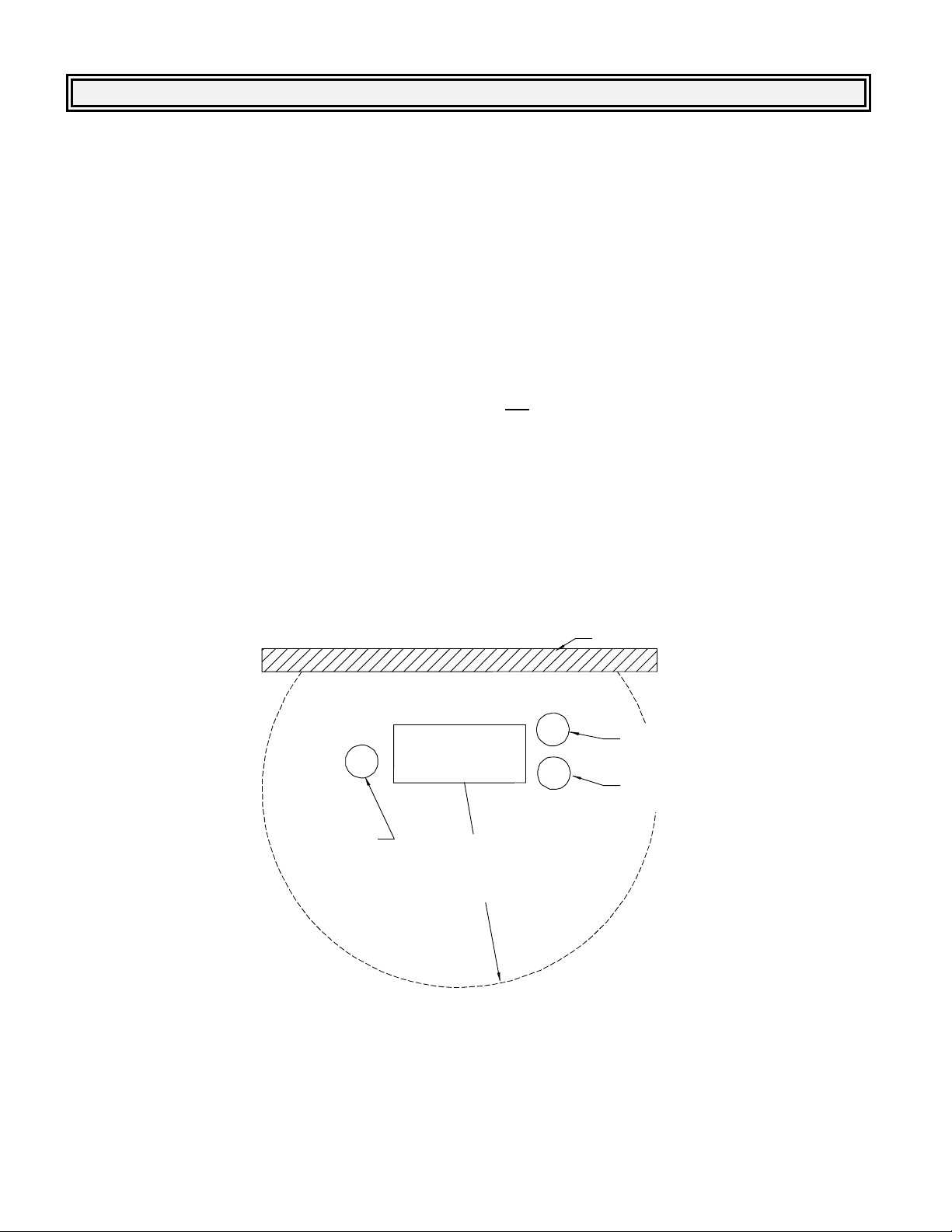
CHOOSING A LOCATION:
Locate the BE-55C in a cool, ventilated area. The unit is not weatherproof, must be installed in a
sheltered area and protected from freezing. The maximum allowable ambient temperature for operation
is 100F (38ºC). The unit produces approximately 42,000 BTU’s per hour of heat. Adequate ventilation
must be provided to insure that the ambient temperature does not exceed 100ºF (38ºC).
Make sure there is sufficient space behind the unit (12 inches minimum) to allow proper air circulation
through the heat exchangers. Space for two drums is required on both sides of the BE-55C. Also
verify that there are no flammables or combustibles used or stored within 20 feet of the unit (see Safety
Precautions section of this manual). It’s a good idea to keep the BE-55C mounted to it’s shipping skid
in the event that the unit needs to be moved or transported to a different location.
WASTE COOLANT
DRUM
TOP VIEW
INSTALL
12 INCHES MINIMUM
FROM WALL
BE-55C
DO NOT USE
OR STORE
FLAMMABLES OR
COMBUSTIBLES WITHIN
20 FEET OF UNIT
WALL
PROCESSED
WATER DRUM
PROCESSED
GLYCOL DRUM
4
Page 6
FILL & DRAIN ASSEMBLY:
p
Remove the plugs from the Fill Port and the Drain Port on the left side of the BE-55C. Assemble and
install the Fill Pipe Assembly onto the Fill Port and the Drain Pipe Assembly onto the Drain Port.
The Drain Pipe Assembly consists of two parts. Thread the part with the tee onto the nipple of the
drain port, and the second part (with the flare fitting) into the top of the tee. Turn the parts as
necessary to allow the valves to operate freely.
Use plumber’s Teflon tape and a pipe wrench to ensure tight, leak-free connections. Refer to the
“Parts Location Diagram” for the piping configurations.
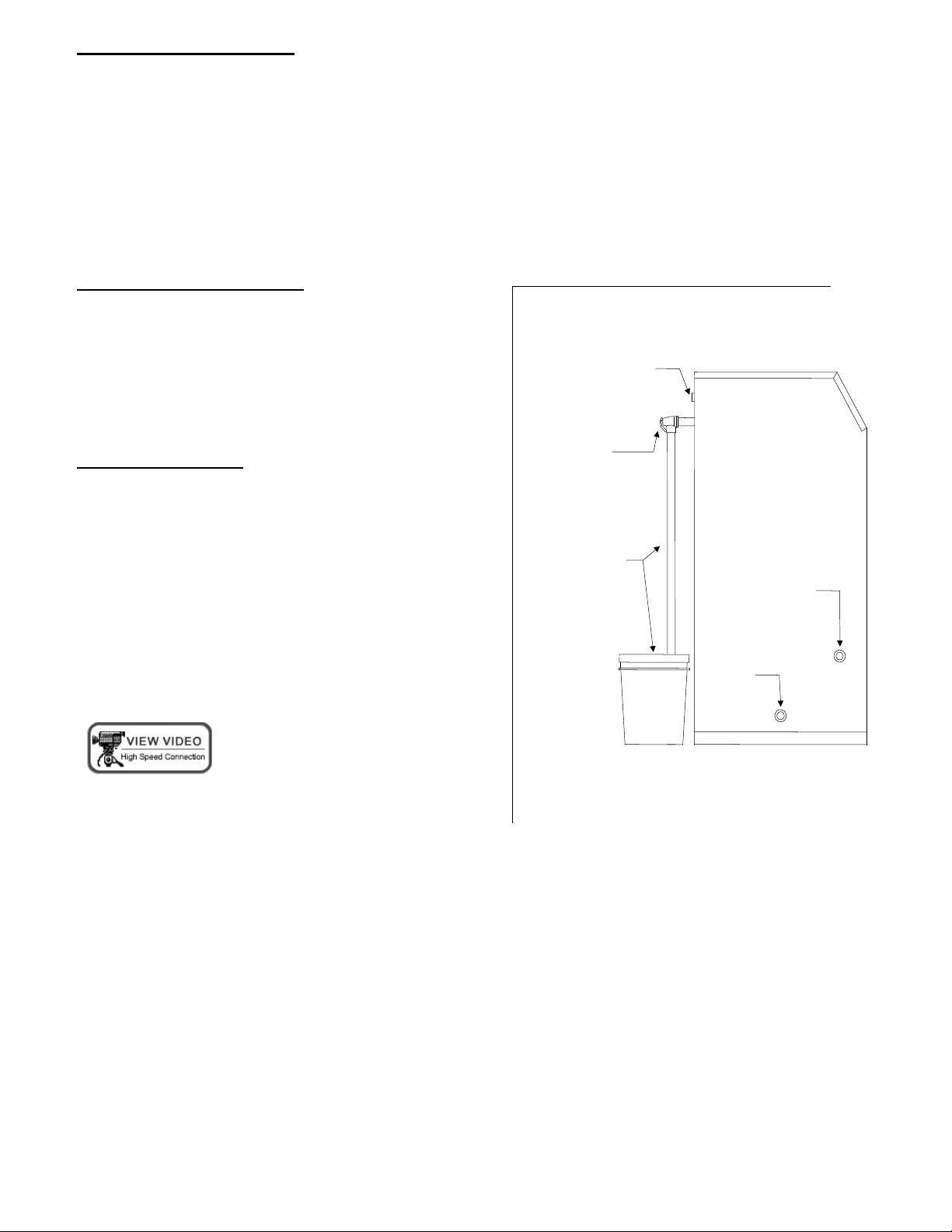
PRESSURE RELIEF VALVE:
Screw the pressure relief valve onto the connection on
the back of the cabinet. Use piping capable of handling
temperatures up to 400F. This piping should be
routed into a receiving container capable of holding 5
AIR CONNECTION
gallons of hot liquid (e.g., a 5 gallon metal pail with a
bung opening in the lid).
AIR CONNECTIONS:
Connect a filtered air supply to the BE-55C via the 1/4-
INST ALL
PRESSURE
RELIEF VALVE
HERE
inch FNPT connector located on the rear panel of the
unit. Maximum allowable inlet pressure is 125 psi. An
internal regulator is installed to reduce the air supply to
10 psi. Air is used for the Drain Assist feature for the
Process Tank.
CUSTOMER
SUPPLIED
CUSTOMER
1”NPT x 3 1/2’
SUPPLIED
PIPING AND
PIPING AND
5-GALLON
BUCKET
BUCKET
FILL PORT
NOTE: Do not change factory setting on internal
regulator.
DRAIN
PORT
BE-55C Installation and
eration
O
LEFT SIDE VIEW
5
Page 7
ELECTRICAL CONNECTIONS:
The BE-55C requires a 208-240 volt, 3 phase, 60 Hz (special 50 Hz units are available) and 40-amp
electrical service with ground. Process times are longer at voltages less than 240V (up to 25% longer
when incoming voltage is 208V). Electrical connections should be performed by a qualified electrician
and in accordance with local codes. A minimum of 10 gauge copper wire must be used.
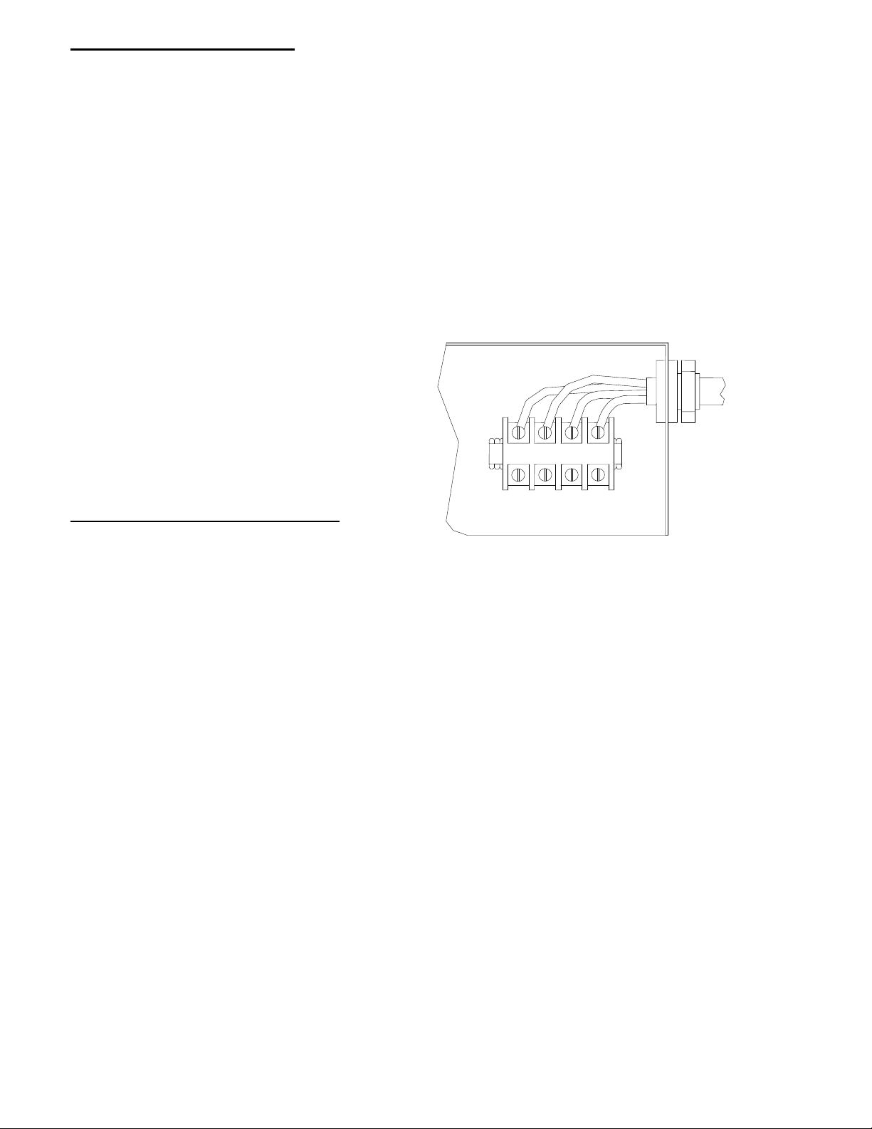
1. Remove the front panel of the BE-55C. Remove the cover from the circuit box.
2. Run the wiring through the grommetted hole in the rear panel of the unit and into the BE-55C’s
circuit box. Bring the wire into the Circuit Box and secure the wire with the strain relief.
3. Connect the wiring to the upper terminal block connections labeled “L1”, “L2”, “L3”, and “G”. Be
certain that the connections are correct and solidly attached to the terminal block.
NOTE: The BE-55C’s circuitry incorporates
a “phase control relay” (orange colored
device in circuit box) that will not allow the
unit to operate if the field connections are
incorrect. This prevents the three phase
motors from rotating in the wrong direction.
INCOMING
POWER
If “phase control relay” light is not lit, switch
any two incoming power wires to correct
phasing.
L1 L2 L3 G
PRIMING THE CIRCULATION PUMP:
1. Locate and remove the square access
panel in the top of the BE-55C.
2. Remove the lid from the Pump Reservoir tank, and fill with 5 gallons of FTI pump primer. Be careful
not to splash when pouring. Ensure that the liquid level in the pump reservoir is maintained at all
times.
3. Replace the Pump Reservoir lid and access panel cover when finished.
NOTE: If a Start-up Kit was not purchased, water can be substituted for the FTI Pump Primer but will
result in slightly diluted Processed Coolant for the first run.
6
Page 8

~ Sequence of Operation ~
The BE-55C requires minimal operator involvement. Once the unit is filled with waste coolant and
started, the unit can operate virtually unattended until the process is complete. Following is the normal
sequence of operation for a waste coolant run in the BE-55C.
FILL - The Fill Hose is inserted into a 55-gallon waste coolant drum. A Fill Switch on the BE-55C
starts a vacuum pump. As a vacuum is formed in the process tank, the Fill Valve is opened to draw
in the waste coolant. When the drum is emptied, the operator switches the Fill Switch off. An
overfill sensor prevents more than 55 gallons from entering the tank.
WATER PROCESS - The BE-55C Process On/off Switch is depressed, starting the heaters and the
heat-exchanger circulating pump. As the water is heated and vaporizes, it passes through a
condenser and reforms into a distilled water product. This distilled water product gravity drains into
the processed water receiving drum.
GLYCOL PROCESS - When most of the water has been processed, the temperature inside the
process tank will begin to rise. When this temperature reaches 280F, a switch closes, energizing
the divert solenoid valve and creating a vacuum. At this point, the upper heaters de-energize and
remain off for the remainder of the cycle. During this portion of the process, the glycol is vaporized
under a vacuum (reducing its boiling point).
AUTO SHUTDOWN - The BE-55C will automatically terminate the process when the liquid in the
process tank reaches a low level (approximately 5-7 gallons). This low level sensor de-activates
the Process On/off Switch, shutting the unit off.
DRAIN ASSIST - After the cycle is complete, and the residue in the tank has cooled for two to three
hours, the residues must be drained into a residue collection container. The Drain Assist Switch is
depressed (activating the air supply solenoid) and the Drain Valve is opened until the residues stop
flowing.
REINHIBIT - After the process is complete, the Processed Glycol can be mixed with Processed
Water or low mineral content tap water to obtain the desired freeze/boil protection and reinhibited
with FTI’s “BE-Series Engine Coolant Treatment” to re-make engine coolant.
MAINTENANCE - As recommended by this manual, periodic flushing and fluid level checks should
be performed as outlined to insure proper operation and continued quality of recycled product.
7
Page 9
~ Operating the BE-55C ~
CAUTION: ALWAYS WEAR SAFETY GOGGLES, PROTECTIVE CLOTHING, AND GLOVES
WHEN OPERATING THIS UNIT.
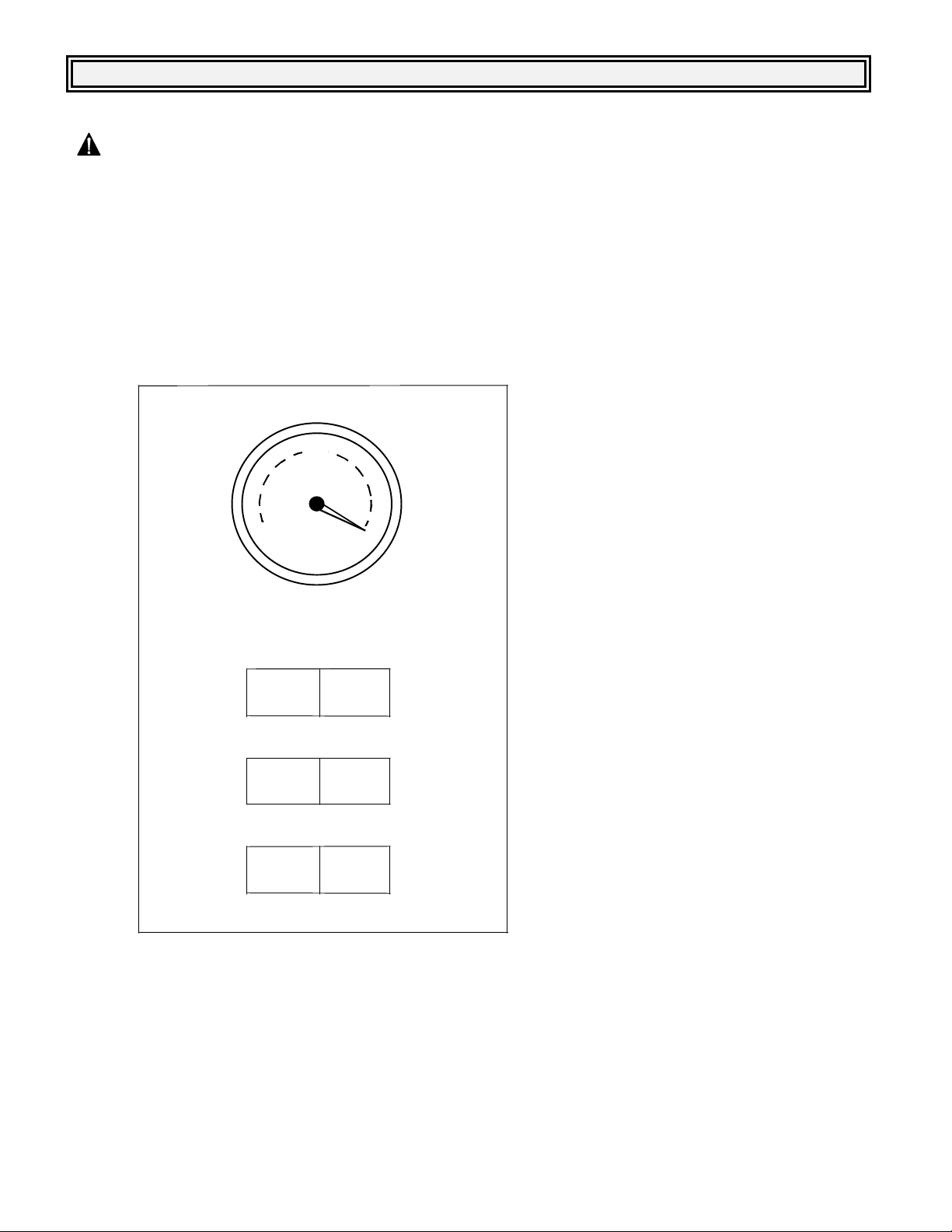
1. Position your two collection drums to the right of the BE-55C and insert the unit’s hoses into the
drums. Take care to not allow the level of the processed liquid to cover these hoses to prevent
over-pressure or liquid from being drawn back into the process tank.
2. Insert the clear, braided Fill Hose into your waste coolant drum.
3. Close both the Fill Valve and the Drain Valve.
4. Depress the Fill Switch. The vacuum will begin to register on the Vacuum Gage. When the
vacuum reaches -10” to - 15” Hg.,
open the Fill Valve to allow the waste
coolant to be drawn into the process
15
30
0
VACUUM GAUGE
PROCESS
OFF
ON
FILL
OFF
ON
DRAIN ASSIST
OFF ON
5. Depress the Process Switch to the ON position. The switch’s light will illuminate, the cycle begins,
and will now function automatically. When the process is complete (usually less than 20 hours), the
Process Switch will move to the OFF position, and the light will go out.
NOTE: If the Fill Switch illuminates during the process while it is in the OFF position, the distillate
overtemp switch has activated. This indicates that the unit is in a cool-down mode. The process will
resume when the distillate temperature cools. See “TAS4 keeps tripping due to cooling system
problems” on page 22.
tank. The Fill Switch will
automatically disengage when
approximately 55 gallons is drawn
into the tank. Close the Fill Valve. If
less than 55 gallons is to be
processed, manually disengage the
Fill Switch when the waste coolant
drum is empty and close the Fill
Valve.
NOTE: Do not over-fill the process tank.
Fill only from a 55-gallon drum.
Processing batches less than 55 gallons
can result in inconsistent yields.
NOTE: The BE-55C is not designed to
process motor oils. Every attempt must
be made to prevent oil and debris from
entering the Process Tank. Failure to do
so will result in poor quality product and
could damage the BE-55C.
8
Page 10

6. The Processed Water and Processed Glycol are now ready for mixing and reinhibiting (refer to the
Adding Reinhibitors/Freeze Point Check instructions at the end of the manual). The Processed
Glycol normally contains approximately 10-20% water.
7. Allow the BE-55C to cool for at least two to three hours.
NOTE: Warm residues flow easier than cold residues, allowing the tank to be more completely
drained of residue.
8. Use the Drain Assist to remove the residues from the process tank to a waste container.
CAUTION: LIQUID DRAINED FROM THE PROCESS TANK CAN REMAIN VERY HOT FOR
MANY HOURS. USE EXTREME CARE WHEN DRAINING.
Place the Black Drain Hose into a metal waste container. Depress the Drain Assist Switch and
carefully open the Drain Valve. Air will begin to push the residue into your waste container. When
residue no longer is flowing, and only air is coming out of the hose, close the Drain Valve and push
the Drain Assist Switch to the “off” position. Open the manual drain valve and allow any remaining
liquid to flow into a catch pan, and then close the valve.
NOTE: Use only the special high temperature Black Drain Hose on the air assisted residue drain.
Other hose types may burst due to high temperature.
9. Dispose of residue properly in accordance with Federal, State and Local regulations.
10. Perform maintenance as outlined in the “Maintenance Schedule” section of this manual.
NOTE: Residue must be drained after every run. Failure to do so will result in poor quality product
and will damage the BE-55C.
NOTE: If less than 5 gallons of residue is drained, or the material is the consistency of tar, a
cleaning cycle must be performed before attempting another waste coolant cycle (refer to the
“Maintenance Schedule” section of this manual).
NOTE: Never re-run residue or mix residue with waste coolant to re-run. Doing so will result in
poor quality product and will damage the BE-55C.
9
Page 11

Finish Thompson Premium Inhibitor Blending Instructions
Finish Thompson’s Premium Inhibitor is a fully formulated antifreeze inhibitor package designed to
restore critical corrosion protection agents to glycol recycled with BE Series distillation systems. When
properly inhibited, the recycled glycol meets and exceeds various performance specifications including
ASTM D-3306, D-4985, D-6210 and TMC RP-329.
This one part formula is easy to use and economical. Because it works on all engine types, it eliminates
the need to have more than one formula for automotive and heavy-duty engines. In addition, it can be
used on either ethylene or propylene glycol.
When used with diesel engines, no pre-charge dose of supplemental coolant additives is required
(normal SCA maintenance is required).
Blending Instructions:
Use only ethylene or propylene glycol recycled using the BE Series distillation process.
Glycol must be between 50º and 100º Fahrenheit (10º and 38º Celsius) to be properly inhibited.
Begin mixing the glycol and slowly pour 2 ½ fluid ounces of Finish Thompson Premium Inhibitor for
every gallon of concentrated glycol produced by the BE Series distillation system. Continue to mix for
approximately fifteen minutes to ensure complete blending.
If a 50/50 mixture of glycol and water is desired, add the appropriate amount of low mineral content or
distilled water until the freeze point is –34º F (-37ºC). Use a high quality device such as a refractometer
to verify freeze point.
Note: Glycol produced by the BE Series distillation process can contain 10-20% water, do not mix 50%
water with the distilled glycol.
Store Finish Thompson Premium Inhibitor above 40º Fahrenheit (5º Celsius)
Use part number J104016 to reorder additional five-gallon pails of inhibitor
If you have any questions concerning Finish Thompson Premium Inhibitor, contact FTI sales by
telephone at 814-455-4478, by fax at 814-455-8518 or by e-mail at fti@finishthompson.com
10
Page 12

~ Maintenance Schedule ~
CAUTION: ALWAYS WEAR SAFETY GOGGLES, PROTECTIVE CLOTHING, AND GLOVES
WHEN WORKING ON OR WITH THIS UNIT.
CAUTION: NEVER WORK ON OR WITH THIS UNIT WHILE IT IS HOT. ALLOW A MINIMUM
OF TWO HOURS COOL-DOWN TIME.
EVERY CYCLE:
DRAIN RESIDUES - Evacuate all residues from the process tank before attempting a waste coolant
run. If less than 5 gallons of residue drains, perform a cleaning cycle (see “FLUSH” procedure in
the “Weekly” section of the “Maintenance Schedule”). Failure to do so will result in damage to the
BE-55C.
WEEKLY OR EVERY FIVE (5) WASTE COOLANT RUNS:
FLUSH - Perform the following flush cycle in order to maintain quality product and to prevent a
build-up of material on the inside of the Process tank. Failure to do so will result in damage to the
BE-55C. For best results, perform a “detergent flush” to help remove oily deposits.
1. By gravity draining, remove as much residue as possible from the Process Tank.
2. Fill the Process Tank with 25 gallons of clear water (follow the filling procedure outlined in the
“Operating the BE-55C” section of this manual). To perform a “detergent flush”, dissolve 4-6 cups
of non-sudsing automatic dishwasher detergent such as Cascade
in the 25 gallons of clear water
before filling the process tank.
3. Depress the Process Switch to the ON position and allow the unit to run for two hours. Then turn
the unit off.
NOTE: Do not allow this cycle to run longer than two hours for the cleaning process. Doing so can
damage the BE-55C.
4. Allow the BE-55C to cool for at least 1/2 hour.
5. Place the Black Drain Hose into a metal waste container. Depress the Drain Assist Switch and
carefully open the Drain Valve. Air will begin to push the residues into your waste container. When
residue no longer is flowing, and only air is coming out of the hose, close the Drain Valve and push
the Drain Assist Switch to the “off” position. Open the manual drain valve and allow any remaining
liquid to flow into a catch pan, and then close the valve.
NOTE: If the drained water is heavy with particulate matter or brown to black in color, the cleaning
process must be repeated until the water begins to drain somewhat clear. Failure to do so will
damage the BE-55C.
CHECK LIQUID LEVELS - Verify that the liquid in the Pump Reservoir is filled to the proper level
(refer to “Priming the Circulation Pump” section of this manual). If low, top off with clear water or
processed glycol.
11
Page 13

BI-MONTHLY:
HEAT EXCHANGERS (radiators) - Clean the finned-tube surfaces of the heat exchangers by
carefully blowing compressed air through the fins from the outside to the inside. Be careful not to
allow the compressed air to bend the fins. Use a shopvac on the inside to help collect the dust.
ANNUALLY:
PUMP RESERVOIR - Drain and clean the Pump Reservoir. On the bottom of the Pump Reservoir
is a drain valve and drain hose. Place a five gallon bucket under the reservoir, insert the drain hose
into the bucket, open the drain valve and drain the glycol from the Pump Reservoir. Close the drain
valve. Wipe off any oily residues from the tank surfaces and pump. Re-fill with processed glycol
(water can be substituted, but will result in diluted processed glycol for the next run).
PROCESS TANK - Clean out the bottom of the Process Tank by removing the Heater Assembly
and scooping out any accumulated residues, see “BE-55C Heater Replacement/Tank Access” on
page 34.
INTERMITTENT USE AND STORAGE:
Take additional precautions if the BE unit is used intermittently (less than once per week) or is placed in
storage (more than one month). Residues left in mechanical components can become “sticky”, liquid
levels can evaporate, and metal parts can corrode. Perform the following maintenance to help prevent
problems with intermittent use and storage:
Intermittent use:
DRAIN RESIDUES - Do not allow the residues to sit in the Process Tank for any length of time.
Drain according to the “Maintenance Schedule” section of this manual.
FLUSH - Flush out any residual residues and clean the Distillate Piping by performing a flush
according to the “Maintenance Schedule” section of this manual.
Before restarting with intermittent use:
CHECK LIQUID LEVELS - Verify that the liquid in the Pump Reservoir is filled to the proper level.
If low, top off with Pump Primer, Recycled Glycol, or clear water until the reservoir overflows out of
the Recycled Glycol hose.
12
Page 14

Storing the BE unit:
PREPARE THE COOLING SYSTEM - Drain and clean the Pump Reservoir per the instructions in
the “Maintenance Schedule” section of this manual. Re-fill the Pump Reservoir with a 50/50 mix of
water and new antifreeze or recycled antifreeze that contains reinhibitor. This will help to
protect the radiator and piping from corrosion (the antifreeze will be circulated through the cooling
system during the next step). Replace the cover to the Pump Reservoir.
CLEAN THE PROCESS TANK - Drain all residues. Perform a “detergent flush” of the Process
Tank per the instructions in the “Maintenance Schedule” section of this manual.
DISCONNECT POWER - Turn off the electrical power (at the main circuit breaker) for the BE unit.
If other equipment is connected to the same circuit, disconnect the wiring to the BE unit.
Before restarting after storage:
RECONNECT POWER - Return the electrical power supply to the BE unit.
HEAT EXCHANGER - Clean the finned-tube surfaces of the heat-exchangers by carefully blowing
compressed air through the fins from the outside to the inside.
PREPARE THE COOLING SYSTEM - Drain the antifreeze from the Pump Reservoir. Refill the
reservoir with Pump Primer, Recycled Glycol, or clear water until the reservoir overflows out of the
Recycled Glycol hose. The antifreeze is removed so that the newly Recycled Glycol does not
become too rich in inhibitors once the reinhibitor package is added. Replace the cover to the Pump
Reservoir.
13
Page 15

~ Troubleshooting ~
The following are a few tips for diagnosing some problems you may experience during the use
of your BE-55C. If the following suggestions do not pinpoint the cause of your problem, contact
FTI’s toll-free “Service Hotline” from 8 a.m. to 5 p.m. EST. 1-800-888-3743
CAUTION: ALWAYS WEAR SAFETY GOGGLES, PROTECTIVE CLOTHING, AND GLOVES
WHEN WORKING ON OR WITH THIS UNIT.
CAUTION: NEVER WORK ON OR WITH THIS UNIT WHILE IT IS HOT. ALLOW A MINIMUM OF
TWO HOURS COOL-DOWN TIME.
CAUTION: A QUALIFIED ELECTRICIAN SHOULD PERFORM ANY ELECTRICAL TESTS
PERFORMED ON THIS UNIT.
~ Table of Contents ~
Unit will not turn on 15
Circuit Breaker at power main keeps tripping 17
Autofill not functioning 17
Low vacuum readings after divert (less than -19” Hg.) 19
Premature Shutdown 20
Unit runs longer than 24 hours with nothing or little produced 22
Discolored Recycled Glycol 23
Water in processed Glycol 24
Glycol in processed Glycol 24
All distillate go into the Processed Water drum 24
All distillate go into the Recycled Glycol drum 25
Unit will not drain or less than 7-gallons of residue drained 25
Pressure Relief Valve Keeps Discharging 28
Divert Valve Repair or Replacement 29
Vacuum / Circulation Pump Servicing 32
Pump and Motor Disassembly 33
Heater Replacement / Tank Access 35
Specifications 36
Common Spare Parts 36
Parts Location Diagram 37
Hose Layout Diagram 38
Electrical Schematic 39
14
Page 16

PROBLEM: UNIT WILL NOT TURN ON.
Possible Cause 1: No or Improper Electrical Power.
No power to the unit, check main circuit breaker. If tripped, verify correct wiring and electrical
supply to the BE unit (see pg. 6 for electrical connections).
Verify that the LED on the phase control relay is illuminated. If not, interchange any two of the three
phase wires.
Unit has not cooled down sufficiently from the previous batch. Allow unit to cool.
If the wiring to the unit is as above and correct, refer to the “Problem: Circuit breaker keeps tripping” in
the “Troubleshooting Tests and Repairs” section of this manual.
Possible cause 2: Safety overtemp sensor(s) activated
CAUTION: Disconnect electrical power to the BE unit at the main breaker before performing
tests on the temperature activated Switches (TAS)
Check TAS2 for continuity. This is a “normally closed” switch, threaded into the front of the process
tank behind the heaters covers. It is a 1/2” diameter white ceramic sensor with a brass hex base and
two wires (#1L1 and #10) connected to it. Check for continuity between these wires. See “Parts
Location Diagram” on page 36.
If there is continuity between the two terminals of TAS2, the switch is O.K.
If there is not continuity between the two terminals of TAS2, the sensor has tripped.
These units’s use a switch rated for 385ºF. This will be indicated by “L385” written on the sensor. This
sensor should reset at 285ºF. If the process tank is cool and this sensor has not reset, then replace
TAS2.
If TAS2 has tripped, this indicates that the process tank is overheating. This can occur if there is a
residue build-up in the tank, or if the low-level control system does not turn off the unit with 5-7 gallons
of liquid left in the Process Tank. Perform a “detergent flush” and check the low-level control system.
See “Low Level Control Probe is shorted to ground” on page 26.
Check TAS4 for continuity. This is a “normally closed” switch threaded into the Distillate Piping between
the Condenser and the Divert Solenoid Valve. It is a 1/2” diameter white ceramic sensor with a brass
hex base and two wires (#18A and #18) connected to it. See “Parts Location Diagram” on page 36.
If there is continuity between the two terminals of TAS4, the switch is O.K.
If there is not continuity between the two terminals of TAS4, the sensor has tripped.
TAS4 is a switch rated for 180ºF. This will be indicated by “L180” written on the sensor. This sensor
should reset at 100ºF. If TAS4 has tripped, this indicates that the Distillate Piping has overheated. One
way this can occur is if the operator attempts to fill the Process Tank when the unit is still hot. The
uncooled steam created can trip TAS4, which will prevent the unit’s heaters from turning on (fans will
still run and the Autofill switch (SW2) will be illuminated in the off position). If the unit is cool TAS4
should have reset, if it has not reset, TAS4 is defective and must be replaced.
15
Page 17

Possible Cause 3: Low Level control system not satisfied.
Insufficient liquid level in Process Tank. Verify that the Process tank has been filled (minimum
8-gallons).
Check the red LED on the Low Level Control Board (located in the upper left corner of the BE’s circuit
box, this will be the second board). When liquid touches the Level Probe, it grounds the probe and
lights the LED on the Level Control Board.
If the LED is lit, proceed to Possible Cause 4.
If the LED is not lit, and technician is certain that liquid is in the Process Tank, the unit is not
sensing the liquid.
Check the Level Probes wiring. Touch the probe’s wire (#23) to the probe’s pipe. If the LED lights,
remove the probe and check for a clog in the pipe that would prevent liquid from reaching the probe.
Also check continuity between the probe’s wire terminal and the probe’s rod. If there is no continuity,
the Level Probe is defective and must be replaced.
If the LED still does not light, check the Process Tank’s ground wire connection. This wire is attached to
the Process Tank with a screw (behind the heaters cover). This connection can become corroded and
not allow the Level Control to function. Remove the screw, file the metal clean, and re-attach the wire
with a new screw and new crimp connector. If the screw is too corroded to remove, drill and tap a new
hole for the ground into the same metal slab, next to the old screw.
CAUTION: Do not drill a hole into or through the Process Tank.
Drill into the welded metal slab only.
Maximum drill depth is 1/4”.
If everything above checks out O.K, then check for voltage (240V) across wires #26 and L2 to the
on/off switch, if no voltage is present, then the Level Control Board is defective and must be replaced.
Possible Cause 4: On/Off Switch is Defective
WARNING: Electrical shock hazard present. A qualified electrician should perform
electrical servicing.
With power on to the unit, first check if 240 volts are present at the switch (across wires #26 and
#L2). If voltage is present, depress the On/Off switch to the on position and check for 240 volts
across wires #13 and #18A.
If no voltage is present at wire #13 and #18A with the switch in the on position and there is voltage
at wires #26 and #L2, then the switch is defective and must be replaced.
16
Page 18

PROBLEM: CIRCUIT BREAKER AT POWER MAIN KEEPS TRIPPING
Possible Cause 1: Wiring short to ground
Check all wires for continuity to ground.
CAUTION: Disconnect electrical power to the BE unit before performing continuity tests on
the circuitry of the BE unit.
Systematically, check every wire connection for continuity to ground. The majority of the wires are
terminated in the circuit box inside the unit. Also check the wires on the On/Off switch and all TAS’s.
The only wires in the entire electrical circuitry of the BE unit that should be grounded are wires
#22 and #23 from the Level Control Boards. Any other problems or electrical shorts to ground must
be eliminated or damage to electrical components will reoccur.
PROBLEM: AUTOFILL NOT FUNCTIONING
Possible Cause 1: The tank is already full.
Check the status of the LED on the High Level Control Board.
If LED is lit, the unit is full or the High Level Control Boards probe has become grounded. Unplug
wire #22, the LED should turn off:
1. If it doesn’t, the High Level Control Board is bad.
2. If it does, the unit is already full or the level probe in the top of the tank is sensing liquid (the probe
could be bad or debris could cause it to have a ground path to the tank).
Possible Cause 2: Tripped Switch
CAUTION: Disconnect electrical power to the BE unit before performing tests on
the temperature activated Switches (TAS)
Check if the overload on the Pump and Fans motor overload is tripped (red pin), if so, reset.
Check to see if TAS2 (System Over-Temp) has tripped, this is a “normally closed” switch. If the
switch is tripped, refer to the “Process Tank Overheating” section on page 20-21.
Check to see if TAS4 (Distillate Over-Temp) has tripped, this is a “normally closed” switch. If the
switch is tripped, refer to “TAS4 keeps tripping due to cooling problems” section on page 22.
Possible Cause 3: Low or no vacuum being created.
Refer to the PROBLEM: “Low Vacuum Reading” section on page 19.
Possible Cause 4: Not allowing adequate time for vacuum to build up before opening the
ball valve in the fill line.
Allow vacuum to build up to at least –10 in. Hg before opening the ball valve. Allow a couple of
minutes for the vacuum to create flow.
17
Page 19

Possible Cause 5: Stuck/Faulty Divert Solenoid Valve.
Determine whether the Divert Valve is stuck between two positions. During normal operation, the
Distillate Piping is open and at atmospheric pressure during the process. Once the fill process begins,
the Divert Valve switches positions to allow the Distillate Piping and the Process Tank to be under
vacuum.
If the unit “belches” while filling the Process Tank or reads a partial vacuum during the water
process, the Divert Solenoid Valve is stuck between two positions. A stuck Divert Valve can allow
air to enter through the process Water Hose during the vacuum portion of the cycle.
Refer to the “Service Procedures: Divert Valve Repair or Replacement” section on page 29 for further
instruction on servicing the Divert Valve.
Possible Cause 6: Fill Control Relay is Defective
When the Auto-Fill switch (SW2) is depressed it should energize the fill control relay (CR2) causing
relay contacts CR2-3 to close, which in turn will activate contactor C3. This will turn on the pump and
fan motors.
Activate the Auto-Fill switch repeatedly and visually inspect CR2 for proper operation. The opening
and closing of the relay contacts should be noticeable. If the relay appears to be operating, check
for 240V between wires #12 and #18 at relay CR2. If the relay does not operate or the voltage is not
detected, replace the relay.
PROBLEM: LOW VACUUM READING (LESS THAN –19”Hg)
Possible Cause 1: Pump Reservoir is Low
The reservoir only needs to be about 1/2” low to diminish coolant flow through the Aspirator. Fill
pump reservoir with either FTI pump primer or water until the fluid overflows from the Processed
Glycol Hose.
Possible Cause 2: Vacuum Hose Leaking or Deteriorated
Three hoses are subjected to the vacuum generated by the circulation pump. One (red) is for the
vacuum gage and the other two (black) transmit the vacuum from the aspirator to the divert valve
and then to the condenser. These hoses should be inspected for cracks, wear, or weakness
periodically. If there are leaks or if the hoses collapse under vacuum, lower than acceptable
vacuum will result. Replace any suspect hoses. The two black hoses are special reinforced heater
hoses, please call the factory for part numbers if they need to be replaced.
18
Page 20

Possible Cause 3: Debris in Aspirator
Check for foreign matter logged in the Aspirator. The Aspirator is a 2” diameter plastic “tube”
attached to the Circulation Pump’s elbow. Restriction of liquid or airflow will cause low vacuum.
1. Drain the Pump Reservoir of all liquid through the petcock on the bottom of the reservoir.
2. Tilt the pump’s motor to the side to expose the Circulation Pump and the Aspirator.
3. Remove the hose that is attached to a barbed hose fitting on the Aspirator.
4. Remove the Aspirator by unthreading it from the pump’s elbow.
5. Clean out the inside taper of the Aspirator and the three orifices inside (at this time check for any
noticeable signs of corrosion to the brass orifice insert).
6. Remove the barbed hose fitting from the side of the Aspirator. Carefully clean out the tiny hole
under the barbed fitting – a paper clip works well.
7. Reassemble the Aspirator to the pump’s elbow, reconnect all fittings and hoses and refill the Pump
Reservoir to the proper level.
Possible Cause 4: Stuck/Faulty Divert Solenoid Valve.
Refer to possible cause “Autofill Not Functioning” section on page 18.
Possible Cause 5: Faulty Vacuum Gage
The vacuum gage can show inaccurate vacuum levels if it receives shock or is subject to excessive
moisture or temperature. One sign of problems would be if the gage sticks or does not return to
zero. Replace gage if found to be faulty.
PROBLEM: PREMATURE SHUTDOWN (MORE THAN 8 GALLONS IN PROCESS TANK)
Possible Cause 1: Electrical power outage.
If power to the unit is interrupted (even for a second), the unit will shut off. The cycle can be restarted
by pressing the On/off Switch to the ON position (the unit may have to cool before it will restart).
Possible Cause 2: Divert Valve is not diverting.
To check if the divert valve is diverting, turn power off at the main breaker, jump wires #13 and #14 at
TAS3 together and restore power to the unit. At this point, restart the unit, if the vacuum gage does not
register vacuum:
The divert valve solenoid is bad and will need to be replaced, or
It is mechanically stuck in the condensed water position, which will cause the distillation tank to
activate the systems overtemp switch (TAS2), which will shut the unit down leaving more than 8
gallons left in distillation tank. A quick way to check this is by putting your hand over the processed
hose and feel for suction, if you feel suction, the valve is stuck and will need to refer to the
instructions for cleaning it.
If vacuum is created, the divert valve is operating correctly, proceed to check TAS3.
19
Page 21
CAUTION: Disconnect electrical power to the BE unit before performing tests on
the temperature activated Switches (TAS)
Check TAS3. This is a “normally open” switch threaded into the front of the Process Tank behind the
access panel in the insulation. It is a 1/2” diameter white ceramic sensor with a brass hex base and
two wires (#13 and #14) connected to it; it will be the switch on the left hand side. This switch closes
when the process tank reaches 280ºF, which energizes the divert solenoid and upper heater dropout
relay (CR1).
If TAS3 is closed (while the units temperature is above 280ºF), then proceed to Possible
Cause 3. The most accurate method of checking the temperature is to remove TAS3 from its
mount and insert a temperature probe in its place; the use of an infrared gun may also be used.
If TAS3 is open (while the units temperature is above 280ºF), it is defective and needs replaced.
Possible Cause 3: Distillate Piping has overheated from improper cooling.
Refer to the “TAS4 keeps tripping due to cooling problems” on page 22 of this manual.
Possible Cause 4: Process Tank overheating.
CAUTION: Disconnect electrical power to the BE unit before performing tests on
the temperature activated Switches (TAS)
Check TAS2. This is a “normally closed” switch threaded into the front of the Process Tank behind the
access panel in the insulation. It is a 1/2” diameter white ceramic sensor with a brass hex base and
two wires (#1L1 and #10) connected to it. This switch opens if the Process Tank reaches 385F. The
most accurate method of checking the Process Tanks temperature is to remove TAS2 from its mount
and insert a temperature probe in its place; the use of an infrared gun may also be used.
If TAS2 is closed, the switch is O.K.
If TAS2 is open, and the Process Tanks temperature is less than 385ºF, then TAS2 is too sensitive.
Replace TAS2.
If TAS2 is open, and the Process Tanks temperature is greater than 385ºF, a possible cause may
be Residue build-up in the Process Tank, refer to heater plate pull out procedure on page 35.
Causes of Residue Build up
1. Improper maintenance. If the Process Tank is not drained after every run and the Residues are
slow to drain, most likely there is a Residue build-up. Proper maintenance is the key to preventing
a build-up in the Process Tank.
2. Large concentrations of solids in the waste coolant.
3. Oil or transmission fluid is present in the waste coolant. When this is the case, the residue is less
likely to be flushed away with the “Flush” procedure during maintenance.
20
Page 22
Possible Cause 5: Intermittent ground on Process Tank.
Verify that there is more than 7-8 gallons of liquid in the Process Tank and check the red LED on the
Low Level Control Board (located in the upper left corner, second level control board in the BE’s circuit
box).
If the LED is not lit, check the Process Tank’s ground wire connection. This wire is attached to the
Process Tank with a screw (behind the small access panel in the tank’s insulation). This
connection can become corroded and not allow the Level Control to function. Remove the screw,
file the metal clean, and re-attach the wire with a new screw and new crimp connector.
If the screw is too corroded to remove, drill and tap a new hole for the ground into the same metal
slab, next to the old screw.
CAUTION: Do not drill a hole into or through the Process Tank.
Drill into the welded metal slab only. Maximum drill depth is 1/4”.
If the LED on the Level Control Board is lit, the unit should turn on (if the Distillate Piping is cool).
An intermittent connection can be difficult to detect. Watch for flickering of the LED, or attempt to
check the LED as soon as the unit shuts off (prematurely).
PROBLEM: A BATCH TAKES LONGER THAN 24 HOURS TO PROCESS.
Possible Cause 1: High Water Content
Higher than 50% water concentration in the waste coolant. Measure the freeze point of the waste
coolant to verify (-34F / -37ºC freeze point equals 50% water/glycol mixture).
Possible Cause 2: Lower than 240-volt power supply (under load)
Use a buck/boost transformer (autotransformer) to raise the voltage to 240 volts.
Possible Cause 3: TAS4 keeps tripping due to cooling system problems
CAUTION: Disconnect electrical power to the BE unit before performing tests on
the temperature activated Switches (TAS)
Check TAS4. This is a “normally closed” switch threaded into the Distillate Piping between the
Condenser and the Divert Solenoid Valve. It is a 1/2” diameter white ceramic sensor with a brass hex
head base and two wires (#18A and #18) connected to it (it may be covered with a black plastic
sheath), check continuity between these two wires.
NOTE: If the Fill Switch illuminates during the process while it is in the OFF position, the distillate
overtemp switch (TAS4) has activated. This indicates that the unit is in a cool-down mode. The
process will resume when the distillate temperature cools.
If the unit is cool and there is continuity between the two terminals of TAS4, then the switch is o.k.
If the unit is cool and there is not continuity between the two terminals of TAS4, the switch has
tripped and hasn’t reset (replace).
21
Page 23

TAS4 is a switch rated for 180ºF. This will be indicated by “L180” written on the sensor. The sensor
should reset at 100ºF. If TAS4 has tripped, this indicates that the Distillate Piping has overheated. This
can occur if the operator attempts to fill the Process Tank when the BE unit is still hot. The uncooled
steam created can trip TAS4, preventing the unit from turning on. If the unit is cool, TAS4 should have
reset, if not, TAS4 is defective and must be replaced. Other reasons TAS4 will trip:
Pump Reservoir is low. This is the most common cause. The reservoir only needs to be about a
1/2” low to cause poor coolant circulation through the condenser. Top off the reservoir until it
overflows from the Processed Glycol Hose.
Unit installed in too warm of an area. If the ambient temperature around the unit gets above 100ºF,
then the unit can overheat. Verify good, cool ventilation in the installation area. Avoid installations in
small-enclosed rooms or near space heaters and heated parts washers.
Improper air circulation. Clean the finned-tube surfaces of the Radiator by carefully blowing
compressed air through the fins from the inside to the outside. Clean the fins with a degreaser if
necessary. Verify that the rear of the unit is installed a minimum of one foot from a wall. Also be
sure that objects are not stacked around the rear of the Radiator (that will impede air circulation).
Radiator blocked internally from debris or scale. One hint that the Radiator is restricted would be if
the air blown through by the fan does not feel warm (after the machine has been running for
awhile). Perform a flush of the Pump Reservoir and Radiator as outlined in the “Maintenance –
Semi-annually” section. If the low flow or blockage persists, perform a radiator flush using a
commercially available flushing system. Also, worn, kinked, or deteriorated hoses can restrict flow.
Replace any suspect hoses with standard 1/2” automotive heater hose.
PROBLEM: DISTILLATE APPEARS DIRTY OR DISCOLORED.
Possible Cause 1: No problem. This can be normal
Recycled Glycol from the BE unit will have various tints - colorless or green, amber, orange or
brown. This color comes from small amounts of dyes and does not affect the performance of the
product once properly reinhibited.
Possible Cause 2: Oil in Waste Coolant Feed.
Recycled Glycol that is dark brown with a film floating on the top (and a foul odor) is due to
excessive oil in the waste feed. All attempts must be made to eliminate any oil-type contaminates.
Allow the waste coolant to settle in your storage drum, use oil-absorbent pads, and pump the waste
coolant from the center of the storage container, taking care to not pump out the top and the
bottom. A 5-micron pre-filter may also be helpful.
The oily residue will contaminate the process tank and the pump reservoir. Both need to be flushed and
cleaned according to the “maintenance: Semi-annually” section of this manual.
22
Page 24

Possible Cause 3: Residue build-up in Process Tank
If proper maintenance procedures are not strictly adhered to, a build-up of residues can accumulate
inside of the process tank. As the residue bakes to the sides and bottom of the tank, it can breakdown
and smoke from the heat, causing discoloration and a foul odor to the recycled products. This build-up
will eventually cause improper operation of the unit and ultimately damage the heater.
Perform a “detergent flush” of the process tank according to the “Maintenance: Semi-annually” section
of the manual as well as conforming to all recommended procedures in the “Maintenance” section of
this manual. Severe residue build-up may require removal of the heater assembly.
Possible Cause 4: Unit running with low vacuum after divert
If the vacuum level after divert is lower than –19’’Hg, the glycol will be processed at higher than normal
temperatures. This can cause thermal breakdown of the glycol and some of the contaminates.
Return the vacuum performance to its normal levels, refer to “Problem: Low Vacuum Reading”
section of this manual for further instructions.
PROBLEM: WATER IN RECYCLED GLYCOL.
Possible Cause 1: Normal
It is normal to have approximately 10% to 20% water in the Processed Coolant. This will have no
adverse effect on the quality of recycled coolant (water is normally added to antifreeze to obtain the
desired freeze/boil protection). Be certain to account for this water when mixing any additional water
and reinhibitors. Higher than 20% water content can be the result from processing coolant that is low in
glycol content in the first place. Another cause is premature tripping of TAS3.
PROBLEM: GLYCOL IN PROCESSED WATER.
Possible Cause 1: Normal
It is normal to have up to 10% glycol in the Processed Water. Use this Processed water to mix back
into your Processed Coolant to obtain the freeze/boil protection desired.
PROBLEM: ALL DISTILLATE GOES INTO THE PROCESSED WATER DRUM.
Possible Cause 1 & 2: Loose wire on TAS3 or TAS3 is defective or
Stuck/Faulty Divert Solenoid Valve
CAUTION: Disconnect electrical power to the BE unit before performing tests on
the temperature activated Switches (TAS)
Check the wire connections on TAS3. This is a “normally open” switch threaded into the front of the
Process Tank behind the heater access panel. This switch closes when the Process Tank reaches
280ºF. This is supposed to activate the Divert Solenoid Valve to begin processing the glycol. Proceed if
connections are good.
23
Page 25
1. Place a jumper wire between wires #13 and #14. Verify that no wires are touching any metal parts.
2. Restore power to the unit. After about 6 seconds you should hear a click. Depress the Process
Switch (with the TAS3 jumper installed). Wait approximately 10 minutes.
3. Watch the Vacuum Gage. If the unit begins to show vacuum, see how high it goes. It should reach
–19”Hg to 24”Hg. If it does, replace TAS3. If no vacuum forms, the Divert Solenoid Valve is stuck in
the water position. Refer to the Divert Valve Repair or Replacement section of this manual for
further instructions.
PROBLEM: ALL DISTILLATE GOES INTO THE RECYCLED GLYCOL DRUM
Possible Cause 1 & 2: Wire/Terminals on TAS3 are touching or TAS3 is defective or
Stuck/Faulty Divert Valve Solenoid
CAUTION: Disconnect electrical power to the BE unit before performing tests on
the temperature activated Switches (TAS)
The first sign this is going to occur is if the Vacuum Gage begins to show vacuum as soon as the unit is
turned on.
Check TAS3. This is a “normally open” switch threaded into the front of the heater panel behind its
access panel. This switch is supposed to activate the Divert Solenoid Valve to begin processing the
glycol, it should close only when the Process Tank reaches 280ºF.
Check for continuity between TAS3’s two leads. If the Process Tank is cold, and TAS3 is closed,
replace TAS3. If TAS3 is open, then the Divert Solenoid Valve is stuck or faulty. Refer to the service
procedures “Divert Valve Repair or Replacement” section of this manual for further instructions.
PROBLEM: UNIT WILL NOT DRAIN OR LESS THAN 7 GALLONS OF RESIDUE DRAINED.
CAUTION: Do not open the fill valve or drain valve during operation or while the
unit is still hot. Allow a minimum of two hours for cooling before draining or
refilling.
CAUTION: Wear proper eye and skin protection when working with this equipment.
Possible Cause 1: Air Supply not Connected
Air supply not connected. Verify proper air supply hook-up (see “Installation and Start-up” section of
this manual)
Possible Cause 2: Drain Assist Switch is Defective
With power on to the unit, first check for 240 volts at the switch (across wires #7 and #L2), if voltage
is present depress the drain assist switch and check for 240 volts across wires #19 and #20, if no
voltage is present then the switch is defective.
24
Page 26

Possible Cause 3: Clogged Drain Valve
Check for residues or debris blocking the drain valve. This can occur if there were solids or sediment
sucked into the unit with the waste coolant. This can also occur if residue is processed more than once
(which is not recommended) or if residues are continuously remixed into the waste coolant.
1. Place a drain pan (capable of handling hot liquids) under the drain valve and open the valve.
Insert and rotate a stiff wire (like a coat hanger) into the drain valve to attempt to break the clog
free. Use extreme caution, the residues may break loose and rush out. It may be necessary to
remove the drain valve and insert the wire directly into the process tank.
2. Another way that has been proven to be successful is to close all valves and depress the Fill Switch
until a vacuum level of -10” Hg. is reached. Open and close the drain valve rapidly to allow
incoming air to pass through blockage. Fill process tank with 5 gallons of water to dilute residue to
drain.
If blockage does not relieve, remove heater tube assembly and clean out the tank and piping
manually (call factory for further instructions).
After the clog has been cleared, perform a “detergent flush” as outlined in the “Maintenance: Semi-
annually” section of this manual.
Possible Cause 4: Low Level Control Probe is shorted to ground
If the Low Level Control Probe has shorted to ground, the unit will continue running after the residues of
the waste coolant have dropped below the recommended low level. This will allow the unit to continue
heating until all or most of the liquid has evaporated. Check the Low Level Control Probe and it’s wiring
for shorts to ground.
If the Low Level Control Boards LED is not lit, proceed to Possible Cause 5.
If the Process Tank is empty, and the LED is lit, there is a short to ground with the Low Level Probe
or its wiring.
1. Locate the Low Level Probe. It is towards the bottom, right side of the process tank, it is inserted
into a pipe, connected to the tank (the top of the probe resembles a spark plug, there will be a white
wire (#23) attached to the top of it).
2. Remove wire #23 from the probe and check the LED on the Low Level Control Board. If the LED
goes out, then the probe itself is making contact to ground. This can be confirmed by checking
continuity between the terminal on the top of the probe and the pipe.
3. If there is continuity, remove the probe from the pipe, and thoroughly clean the probe and the inside
of the pipe. Residue build-up can form a “bridge” between the probe and the pipe. Check whether
the probe is straight. If the probe is slightly bent, it may touch the side of the pipe. Straighten if
necessary, reinstall the probe and recheck for continuity.
25
Page 27

Possible Cause 5: Low Level Control Board Failure
Caution: Disconnect electrical power to the BE unit before performing tests on the
Low Level Control Board.
If the Low Level Control Board is defective or a false ground has occurred, the unit will continue running
after the waste coolant drops below the recommended low level. This will allow the unit to continue
heating until all or most of the liquid has evaporated. With power to the unit off, check continuity
between wires #18 and 26
if there is no continuity, this part of the system is O.K.
if there is continuity, you will need to check the low level probe. Locate the Low Level Probe. It is
towards the bottom, right side of the process tank, it is inserted into a pipe, connected to the tank
(the top of the probe resembles a spark plug, there will be a white wire (#23) attached to the top of
it).
If there is continuity, remove the probe from the pipe, and thoroughly clean the probe and the inside
of the pipe. Residue build-up can form a “bridge” between the probe and the pipe. Check whether
the probe is straight. If the probe is slightly bent, it may touch the side of the pipe. Straighten if
necessary, reinstall the probe and recheck for continuity.
Possible Cause 6: Air or Water Solenoid is Defective
The air solenoid (SOL3) is “normally closed” and should open when the drain assist switch is
depressed, allowing air pressure to enter the tank (should be regulated at 10psi).
The water solenoid (SOL1) is “normally open” and should close when the drain assist switch is
depressed, preventing the pressurized air from coming out of the processed water hose.
A simple way to check these solenoids is listen for a clicking noise at the solenoid when the switch
is depressed. Furthermore, to check the water solenoid, check to see if air is coming out of the
discharge hose (you would hear a “whooshing” sound), if you do, the valve is not closing and may
need cleaned or replaced.
PROBLEM: PRESSURE RELIEF VALVE KEEPS DISCHARGING
Possible Cause 1: Stuck/Faulty Divert Solenoid Valve.
Determine whether the Divert Valve is stuck between two positions. During normal operation, the
Distillate Piping is open and at atmospheric pressure during the process. Once the glycol process
begins, the Divert Valve switches positions to allow the Distillate Piping and the Process Tank to be
under up to 28” Hg. of vacuum.
If the unit “belches” while filling the Process Tank or reads a partial vacuum during the water
process, the Divert Solenoid Valve is stuck between two positions. A stuck Divert Valve can allow
air to enter through the process Water Hose during the vacuum portion of the cycle.
Refer to the “Service Procedures: Divert Valve Repair or Replacement” section of this manual for
further instruction on servicing the Divert Valve.
26
Page 28

Possible Cause 2: Debris, weak or improper Pressure Relief Valve.
If foreign matter or debris accumulates inside the seat area of the Pressure Relief Valve the valve may
become too sensitive. Further, after time, continuous exposure to vapors from exceptionally acidic
Waste Coolant vapors can degrade and corrode metal parts in the valve, thereby weakening it.
Remove and inspect the Pressure Relief Valve and look for any signs of debris or corrosion. Attempt to
clean the internals of the valve and reinstall. If there are signs of corrosion or damage, replace the
valve. Always replace the Pressure Relief Valve with one rated with identical specifications. A “water
heater” is not acceptable – their temperature rating is too low for the operation of a BE unit. The valve
must be rated for 15 psi and the temperature of at least 425ºF. If in doubt, use a Pressure Relief Valve
supplied by FTI.
Possible Cause 3: Clog in Distillate Piping.
The Pressure Relief Valve is installed to protect the Process Chamber and Distillate Piping from
overpressure in the event of blockage within the piping.
The more likely areas for debris buildup and blockage are in the Distillate Piping before the Divert Valve
or the Condenser. An accumulation of debris can also occur where the Distillate Piping attaches to the
Process Tank.
Attempt to back-flush the blockage out through the Process Tank’s drain.
1. Drain the Process Tank of all liquids.
2. Place a drain pan under the Drain Valve and open the Drain Valve.
3. Attach a water source to the Processed Water Hose (e.g., a garden hose with a nozzle).
4. Turn on the water supply and allow the water to drain into your pan.
If the flushing water seems to be restricted, a teardown and cleaning of the Distillate Piping may be
necessary. Start with the Divert Valve and work your way back to the Process Tank, cleaning out
each component they are removed. Also clean out the opening in the Process Tank. Reassemble
the piping and components using Teflon plumber’s tape to ensure tight, leak-free connections.
DIVERT VALVE REPAIR OR REPLACEMENT:
CAUTION: Disconnect electrical power to the BE unit before repairing or
replacing the Divert Solenoid Valve.
Repairing the Divert Valve:
1. Find the Divert Valve in the piping of the unit. It is brass in color and has a large hex nut on one
side. If you are agile enough, you may be able to reach the Divert Valve through the access hole in
the top panel of the BE unit or from underneath the front opening. Otherwise, remove the top panel
from the unit. Be careful—there are four wires and a hose attached. Set the top on its right side on
top of a crate or other support near the right front corner of the unit.
2. Locate and remove the coil portion of the valve. It is a black box attached to the valve and is held
on with a yellow or silver clip. Remove the clip and slide the coil off of the “stem” of the Divert Valve
and set aside. Do not unwire the coil—replacement of the coil is rarely necessary. However, it’s a
good idea to verify that the wire connections are secure. To check the wire connections, remove the
small screw that holds on the coil’s cover, exposing the wire nuts.
27
Page 29

3. At the base of the Divert Valve’s stem, there will be a large hex nut. Loosen this nut, and carefully
remove the stem. Be careful—there will be a plunger assembly (with spring), and a plastic spring
seat inside the stem.
4. Most likely the plastic spring seat has melted. Remove the plastic spring seat—the Divert Valve
can work without it. Also, clean the rest of the inside of the Divert Valve. There will be two small
metal rods in the valve’s body. Clean them and make sure they move freely. Once re-inserted, the
rods should spring back when pushed into the body. Also clean and dry the inside of the stem.
5. Reassemble the valve. Tighten the hex base of the stem onto the valve body to 175 lb-in. Place the
coil and clip back into position. Set the lid back on the cabinet (if removed) and check that the wires
and hose attached to the lid are not loose or kinked.
6. Test the operation of the repaired Divert Valve by placing a jumper wire between the terminals of
TAS3. Restore power to the BE unit. Verify that there is at least 8 gallons of liquid in the Process
Tank and that the Pump Reservoir is properly filled.
7. Turn the BE unit ON and watch for vacuum on the Vacuum Gage. The vacuum level should begin
to rise until it reaches at least -19”Hg.
If OK, disconnect power, unjump TAS3, put everything back together and try a real recycle run.
If low or no vacuum, hold your finger over the Processed Water Hose. Does the vacuum go up?
If so, replace the Divert Valve body, Part number - J101885.
28
Page 30

SPRING SEAT
PLUNGER ASSEMBLY
PINS
CLIP
SOLENOID COIL
STEM ASSEMBLY
VALVE BODY
DISC
DISC SPRING
HEX CAP
DIVERT SOLENOID VALVE
EXPLODED VIEW
29
Page 31

Replacing the Divert Valve:
1. Find the Divert Valve in the piping of the unit. It is brass in color and has a large hex nut on one
side. If you are agile enough, you may be able to reach the Divert Valve through the access hole in
the top panel of the BE unit or from underneath the front opening. Otherwise, remove the top panel
from the unit. Be careful—there are four wires and a hose attached. Set the top on its right side on
top of a crate or other support near the right front corner of the unit.
2. Locate and remove the coil portion of the valve. It is a black box attached to the valve and is held
on with a yellow or silver clip. Remove the clip and slide the coil off of the “stem” of the Divert Valve
and set aside. Do not unwire the coil—replacement of the coil is rarely necessary. However, its a
good idea to verify that the wire connections are secure. To check the wire connections, remove the
small screw that holds on the coil’s cover, exposing the wire nuts.
3. Remove the two hoses attached by loosening the hose clamps and pulling/cutting them off the
barbed fittings.
4. Unthread and remove the Divert Valve. A 1/4”x close nipple connects the valve body to the Distillate
piping. Remove the nipple and the two barb hose fittings from the old valve.
5. Thread the removed parts onto the new valve body. Use plumber’s Teflon tape to ensure a tight,
leak-free fit. Notice that each port on the new Divert Valve is numbered: Attach the 1/4”x close
nipple to port 1. Attach the two barb hose fittings to port 2 and port 3.
6. Install the Divert Valve onto the Distillate Piping. Position the valve body so that port 2 is facing
straight down and the valve’s stem faces the rear.
7. Reattach the hoses to the barb fittings using the hose clamps. At this time, inspect each hose and
replace any hose that appears weak, worn, or damaged. Use standard 1/2” automotive reinforced
heater hose.
IMPORTANT: It is critical that the proper hoses are attached to the proper ports: Port 2 hose (points to
the right and is in line with the Distillate Piping) leads to the Aspirator in the Pump Reservoir. Port 3
hose (points straight down at 90° from the Distillate Piping) leads out the rear of the BE unit and
becomes the Processed Water Hose.
8. Place the coil and clip back into position. Set the lid back on the cabinet (if removed) and check that
the wires and hose attached to the lid are not loose or kinked.
9. Test the operation of the new Divert Valve by placing a jumper wire between the terminals of TAS3.
Restore power to the BE unit. Verify that there are at least 8 gallons of liquid in the Process Tank
and that the Pump Reservoir is properly filled.
10. Turn the BE unit ON and watch for vacuum on the Vacuum Gage. The vacuum level should begin
to rise until it reaches at least -19”Hg.
If OK, disconnect power, unjump TAS3, put everything back together and try a real recycle run.
If the vacuum does not reach proper level within twenty minutes, check all Distillate Piping connections
for possible leaks. Refer to the “Troubleshooting Tests and Repairs: Low vacuum reading after divert”
section of this manual.
30
Page 32

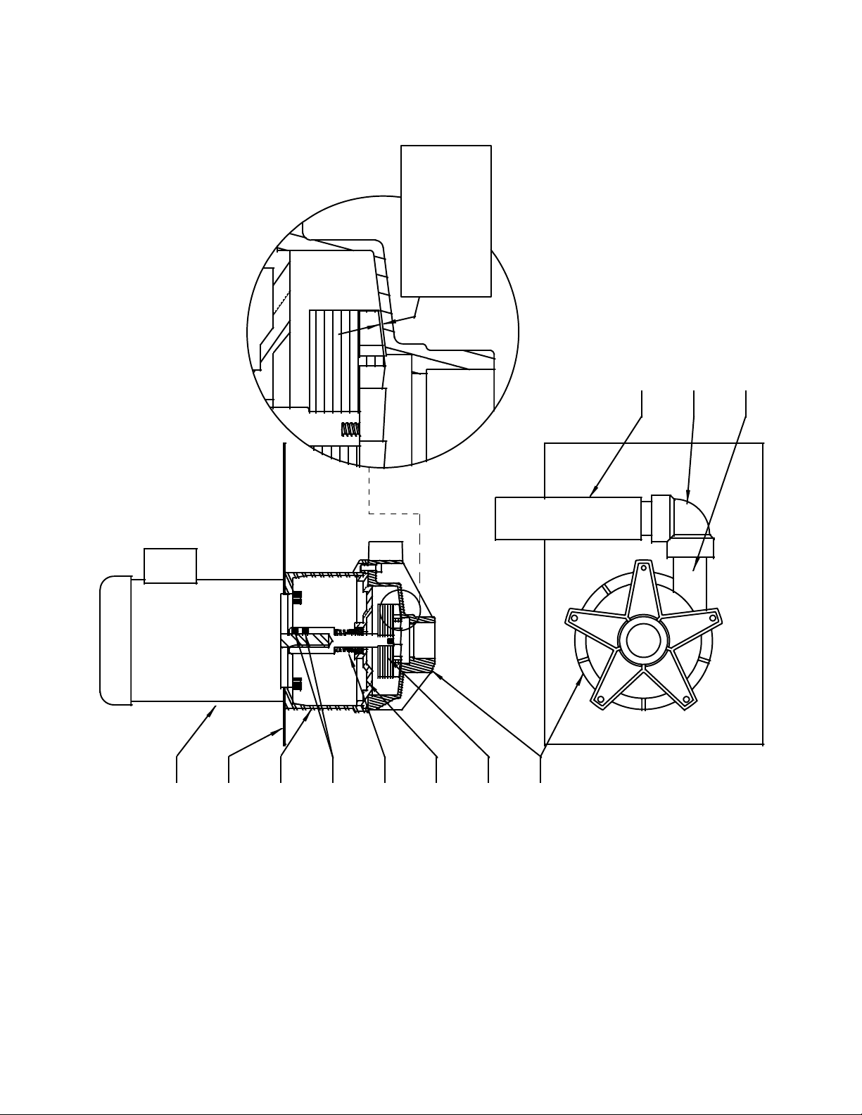
VACUUM/CIRCULATION PUMP SERVICING:
The Vacuum/circulation Pump is located on top of the Pump Reservoir. This centrifugal-type pump is
powered by a close-coupled TEFC electric motor rated at 1/2 hp, 3450 rpm, 230 volt, 3 phase, 60 hertz.
The motor is wired for clock-wise rotation when facing the motor’s fan.
CAUTION: Disconnect electrical power to the BE unit before working on
or repairing the Vacuum/circulation Pump and motor.
PUMP AND MOTOR REMOVAL AND RE-INSTALLATION:
1. Remove the front panel and top panel of the BE unit and set aside. Be careful—there are four
wires and a hose attached to the top panel. Set the top panel on its right side on top of a crate or
other support near the right front corner of the unit. If desired, remove the hose and wires from the
top panel, noting and tagging the proper wire locations for the On/off switch.
2. Open the electrical connection box on the side of the motor. Disconnect the BE unit’s wires #1T1,
1T2 and 1T3 from the motor’s wiring (they are connected with wire nuts). Loosen the plastic
conduit from the motor’s connection box (there is a plastic nut holding the conduit inside the
connection box) and pull the BE unit’s three wires and conduit away from the motor, noting and
tagging the proper wire locations for each lead (if the leads are not connected as they were, it is
possible that the motor will run in the wrong rotation and possibly spin the pumps impeller off its
shaft).
3. Tilt the pump’s motor to the side to expose the Circulation Pump and the Aspirator. Loosen the
hose clamps and remove the two hoses from the pump’s elbow and the Aspirator. Pull the
removed hoses out from the motor’s mounting plate. Also pull the third “open” hose from the
motor’s mounting plate. Lift the entire pump and motor assembly from the Pump Reservoir and set
it on a workbench for further disassembly.
4. After repairs are performed on the pump and
T1
T7
T2
T8
T3
T9
T4
T5 T6
motor, the re-installation of the pump and motor
assembly are the same as the removal, but in the
opposite order.
IMPORTANT: Proper re-wiring of the motor (for
clockwise rotation when facing the motor fan) is
critical. Refer to the motor wiring diagram to the
right for details. Note: If motor rotates in a
counter-clockwise rotation, change any two of the
1T1
1T2
1T3
incoming power supply leads 1T1, 1T2, or 1T3 in
motor conduit box.
PUMP MOTOR WIRING
CLOCKWISE RO TATION
(FACING FAN)
IMPORTANT: Proper reinstallation of the
hoses is critical:
The hose that attaches to the pump’s elbow leads to the radiators.
The hose that attaches to the Aspirator leads to port 2 of the Divert Valve.
The “open” hose leads to the top of the Radiator.
Refer to the “Pump and motor disassembly and reassembly” sections that follow for details on further
servicing the pump and motor.
31
Page 33

PUMP AND MOTOR DISASSEMBLY:
1. Set the pump and motor assembly onto the motor fan cover so that the pump is facing upright on
the workbench.
2. Remove the five socket-head bolts that hold on the pump’s housing and remove the pump housing.
The nuts for the bolts are recessed into the tabs of the motor adapter. Also remove the housing oring.
IMPORTANT: Take note of the orientation of the pump’s discharge (where the elbow is attached) to
allow proper reassembly after repairs.
3. Turn the pump’s impeller until one pair of the impeller shaft’s set screws become visible through the
slots in the motor adapter. Loosen that pair of set screws, then turn the impeller again to locate and
loosen the second pair of set screws.
4. Pull the impeller and impeller shaft away from the motor’s shaft (an assembly of the impeller,
impeller shaft, housing cover, and seal will be removed together).
NOTE: The impeller shaft may be difficult to pull loose from the motor. Attempt to pry on the base of the
impeller shaft with a flat screwdriver through the slots in the motor adapter. Take care to not damage
any pump components while prying.
5. Loosen the four socket-head bolts to remove the motor adapter and motor from the motor mounting
plate.
6. Inspect all parts and replace any parts that appear worn, melted, or corroded.
PUMP AND MOTOR REASSEMBLY:
1. Bolt the motor and motor adapter to the motor mounting plate using the four socket-head bolts.
2. Coat the motor’s shaft with an anti-seize compound. Install the impeller, impeller shaft, housing
cover, and seal assembly onto the motor shaft. DO NOT tighten the impeller shaft’s set screws at
this time.
3. Place the housing o-ring into position on the housing cover. Bolt the housing cover into position
with the pump’s discharge in the same position as it was originally. The nuts for the bolts will insert
into the tabs of the motor adapter.
4. Set the gap between the impeller vanes and the inside of the housing cover to the proper tolerance.
Insert a .020” feeler gage into the suction of the pump’s housing (remove the suction screen if so
equipped). Position the feeler gage on top of one of the impeller’s vanes. Pry up on the base of the
impeller’s shaft (use a flat screwdriver through the slot in the motor adapter) until the feeler gage is
sandwiched between the vane and the housing. Tighten the four set screws in the impeller shaft,
and remove the feeler gage. Re-insert the suction screen (if equipped).
IMPORTANT: It is critical for performance that the gap between the impeller’s vanes and the inside
of the housing cover be set to the proper distance. A gap of .020” +/- .005 is required.
Re-install the pump and motor as outlined in the preceding section, “Pump and motor removal and reinstallation”.
32
Page 34
PUMP & MOTOR
VACUUM/CIRCULATION
R
E
E
!
B
L
E
L
T
C
E
S
N
P
U
A
T
S
I
D
L
A
C
I
T
I
R
C
5
M
I
0
M
0
.
N
G
-
/
E
N
+
I
E
"
S
0
W
U
2
T
O
0
E
.
H
B
D
P
N
A
A
G
R
O
T
A
R
I
P
S
A
W
O
B
L
E
E
G
R
A
H
C
S
I
D
P
M
U
P
R
O
T
O
M
E
T
A
L
P
G
N
I
T
N
U
O
M
R
O
T
O
R
O
T
P
A
D
A
R
O
T
O
M
S
W
E
R
C
S
T
E
S
L
A
E
S
R
E
V
O
C
G
N
I
S
U
O
H
R
E
L
L
E
P
M
I
G
N
I
S
U
O
H
P
M
U
P
M
33
Page 35

BE-55C Heater Replacement/Tank Access: Units with serial number 04532I94 to current
WARNING: Electrical wiring, troubleshooting and repairs should be performed by a qualified
electrician.
Drain residues and flush with clean water.
Allow unit to cool before attempting repair or accessing tank interior.
Disconnect electrical power to the unit before performing these procedures.
1. Remove three screws from the right side of the door located on the front of the unit and open the
door.
2. Remove the two nuts attached to the protective cover and remove the cover from the unit. The
protective cover is located on the lower front portion of the process tank.
3. Note wire numbers and locations on heater elements before removing any wires.
4. Remove wires from heater elements.
5. Note wire numbers and locations on two temperature switches before removing any wires.
6. Remove wires from temperature switches.
7. Remove ground wire.
8. Remove nuts and washers holding stainless steel heater retaining plate in-place.
9. Carefully slide heaters out of tubes.
10. Test each heater for continuity and resistance. Proper resistance is 29-30 ohms.
11. Remove any failed heaters by loosening the brass nut on the face of the heater retaining plate.
Install new heaters and reassemble in reverse order.
12. To access the process tank for cleaning purposes, remove the bolts from the flange/tube assembly.
Remove the flange/tube assembly by pulling it straight out.
13. After the tank has been cleaned, reassemble in reverse order. Do not over tighten flange/tube
assembly bolts.
14. Leave the protective cover off for one run to check for leaks around the gasket. Retighten bolts if
necessary and reinstall the protective cover.
34
Page 36
~ Appendix ~
SPECIFICATIONS:
MODEL: BE-55C
DIMENSIONS:
SHIPPING WEIGHT:
ELECTRICAL REQUIREMENTS:
POWER CONSUMPTION:
48” wide x 30” deep x 63” tall
600 lb
208-240 VAC / 3 phase / 60 hertz / 40 amps
12.8 kilowatts during atmospheric portion of process
6.8 kilowatts during vacuum portion of process
PROCESS TIME:
NORMAL YIELDS:
16-20 hours (55 gallons of 50/50 antifreeze/water @ 240 volts)
31 gallons of Processed Water
18 gallons of Recycled Glycol
6-8 gallons of waste Residue (from 55 gallons of 50/50 mix)
BE-55C COMMON SPARE PARTS:
PART #
DESCRIPTION
PART # DESCRIPTION
J102107 Heater Element (1pc. – 2000 watt) J101486 Contactor
J102200 Heater Plate Gasket (20 holes) J101584 Control Relay
J101558 Heat Exchanger Fan Motor J102540 Vacuum Pump Motor
J101888 Level Control Board J101484 Pressure Relief Valve
J101482 Phase Control Relay J101913 Condenser
J101621
J101119
J102149
TAS2 - 385 Over-temp Switch - N/C
TAS3 - 280 Divert Switch - N/O
TAS4 - 180 Distillate Over-temp Switch – N/C
J100212 Vacuum Gage
J101889 Drain/Fill Hose
J101210 Heat Exchanger (Radiator) J101480 2-Way Air Solenoid
J101481 2-Way Water Solenoid J102263 2-Way Fill Solenoid – N/C
J101892 3-Way Divert Valve w/Solenoid J101890 On/Off Switch
J103141 Drain Assist Switch
105378 2-Way Water Solenoid Repair Kit M101768 Upper Level Probe
M101769 Low Level Probe A102018 Fill Hose w/Wand
A101307 Vacuum Pump Assembly (w/ Motor) M101800 Pump Mounting Plate
108248 Vacuum Pump Assembly (less Motor)
35
Page 37
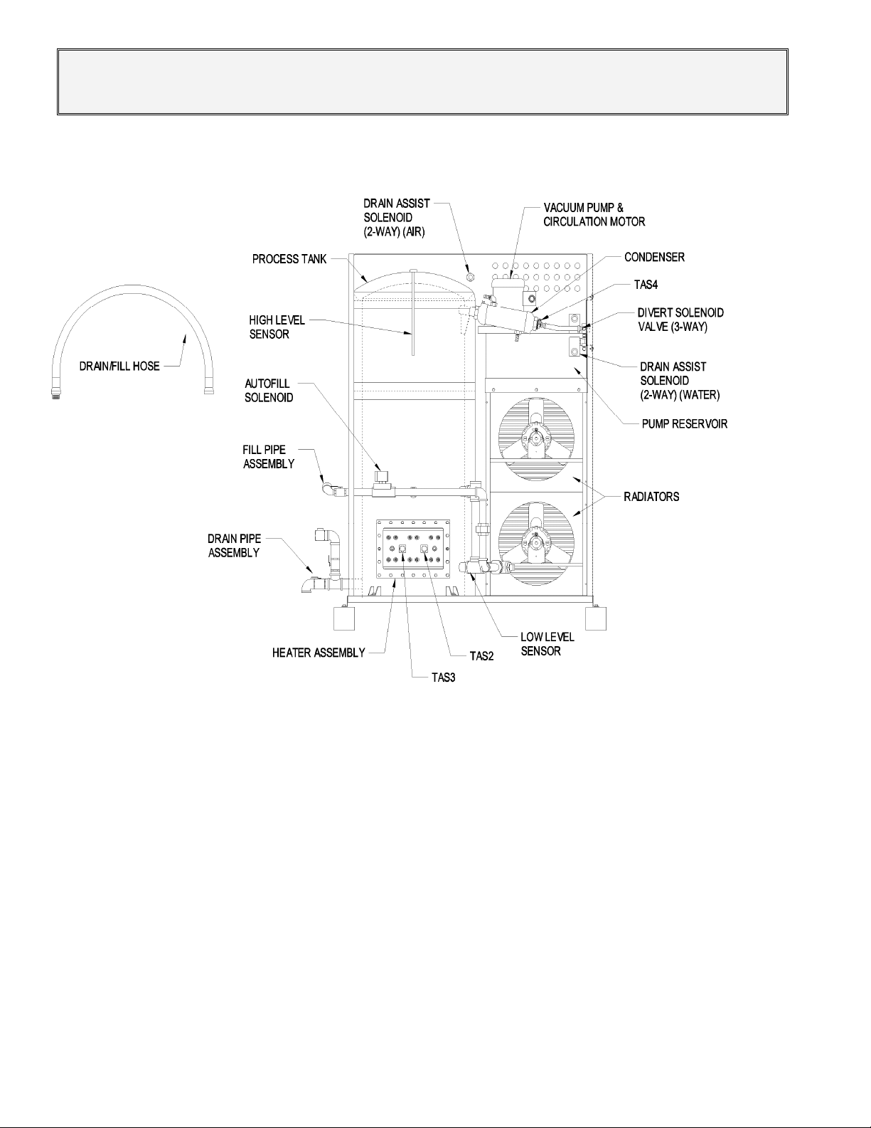
~ BE-55C PARTS LOCATION DIAGRAM ~
36
Page 38
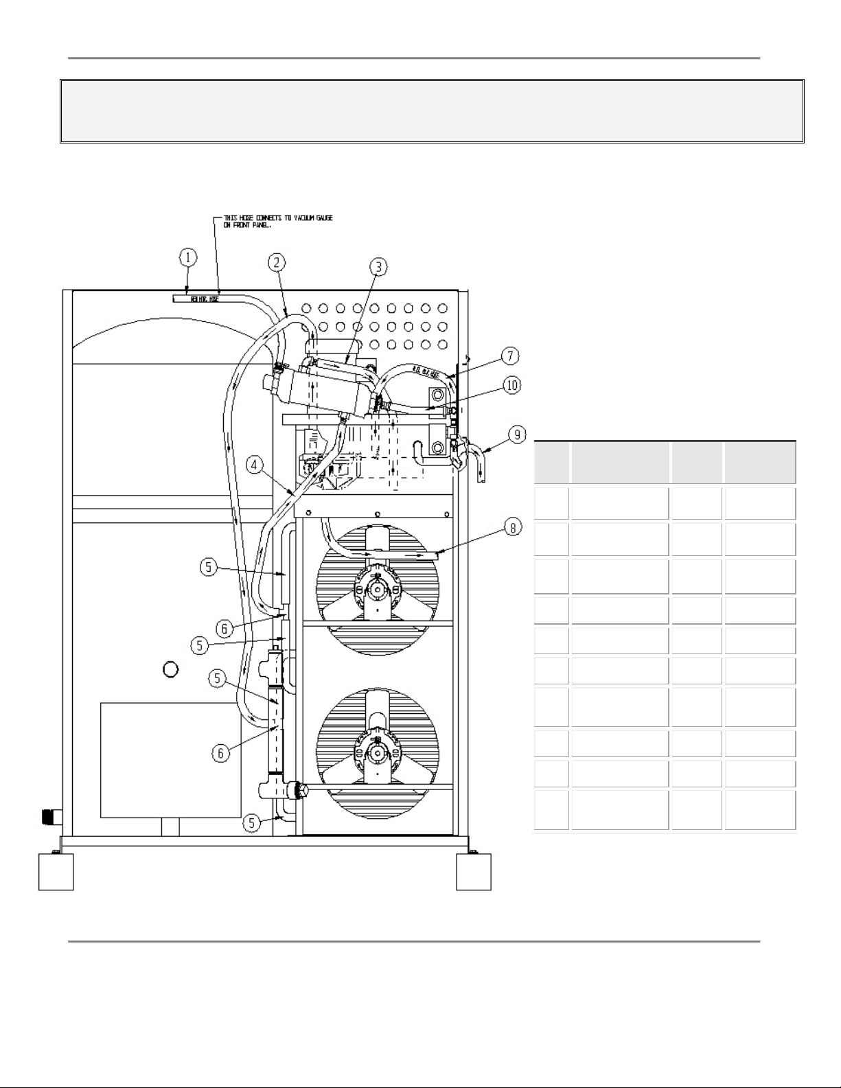
~ BE-55C HOSE LAYOUT DIAGRAM ~
I.D.
#
1 1/4’’ Red
2 1/2’’ Black
3 1/2’’ Black
4 1/2’’ Black
5 1/2’’ Black
6 1/2’’ Nylon Barb
7 1/2’’ Black
8 1/2’’ Black
9 1/2’’ Black
10 1/2’’ Black
Description Length
Vacuum Hose
Heater Hose
Heater Hose
Heater Hose
Heater Hose
Tee Fitting
Heavy-Duty
Heater Hose
Heater Hose
Heater Hose
Heavy-Duty
Heater Hose
Part
Number
36’’ M101740
62” M101735
32” M101736
28” M101736-
14’’ M101738
N/A J101491
36’’ M101202
36’’ M101782
38-
1/2’’
4’’ M101770
1
M101781
37
Page 39

~ BE-55C ELECTRICAL SCHEMATIC ~
38
Page 40

~ Warranty ~
CHEMICAL REACTION DISCLAIMER
The user must exercise primary responsibility in selecting the product's material of construction, which
are compatible with the fluid(s) that come(s) in contact with the product. The user may consult Finish
Thompson, Inc. (manufacturer) and a manufacturer's representative/distributor agent to seek a
recommendation of the product's material of construction that offers the optimum available chemical
compatibility.
However neither Manufacturer nor agent shall be liable for product damage or failure, injuries, nor any
other damage or loss arising out of a reaction, interaction or any chemical effect that occurs between
the materials of the products construction and fluids that come into contact with the product's internals.
WARRANTY
Finish Thompson, Inc (manufacturer) warrants this product to be free of defects in materials and
workmanship for a period of 1 year from date of purchase by original purchaser. If a warranted defect,
which is determined by manufacturer's inspection, occurs within this period, it will be repaired or
replaced at the manufacturer's option, provided (1) the product is submitted with proof of purchase date
and (2) transportation charges are prepaid to the manufacturer. Liability under this warranty is
expressly limited to repairing or replacing the product of parts thereof and is in lieu of any other
warranties, either expressed or implied. This warranty does apply only to normal wear of the product or
components. This warranty does not apply to products or parts broken due to, in whole or in part,
accident, overload, abuse, chemical attack, tampering, or alteration. The manufacturer accepts no
responsibility for product damage or personal injuries sustained when the product is modified in any
way. If this warranty does not apply, the purchaser shall bear all cost for labor, material and
transportation.
Manufacturer shall not be liable for incidental or consequential damages including, but not limited to
process down time, transportation costs, costs associated with replacement or substitution products,
labor costs, product installation or removal costs, or loss of profit. In any and all events, manufacturer’s
liability shall not exceed the purchase price of the product and/or accessories.
Finish Thompson Inc.
921 Greengarden Road
Tech Service Hotline
800-888-3743
Erie, PA 16501-1591 USA
Ph. 814-455-4478
Fax 814-455-8518
Email fti@finishthompson.com
J101485
Rev 7, 7/15/14
39
 Loading...