

Page 1
S
G
N
I
L
C
Y
C
E
R
T
N
A
L
O
O
C
BE-15/15C
Service Manual
Y
S
T
E
M
C
r
o
f
n
i
a
r
o
f
u
n
a
m
m
o
r
f
p
OBSOLETE
n
o
i
t
a
m
s
t
i
n
u
l
l
a
f
1
e
r
d
e
r
u
t
c
o
t
1
9
9
!
t
n
e
s
1
Version 1.3
Octo ber 2005
e
t
e
l
p
m
o
Page 2

“BE SERIES” BE-15/15C SERVICE MANUAL
Version 1.3
Introduction
This service manual and troubleshooting guide for the BE-15/15C takes the technician through an orderly
routine to determine the trouble areas and/or the cause of a problem. In many cases, damaged or defective
parts are the result of failures from other components. This guide’s goal is to get to the root of a problem.
Table of Contents
Safety Precautions
Getting Started
Sequence of Operation
Model Determination
Part Descriptions and Terminology
History of Design Changes
Maintenance Schedule
Minimum Requirements
Intermittent Use and Storage
Troubleshooting Chart
Service Procedures
Troubleshooting Tests and Repairs
Level Control Board Replacement
Divert Valve Repair or Replacement
Heater Band Replacement
Vacuum/circulation Pump Servicing
Location Diagrams and Parts Lists
Electrical Schematics
2
3
3
4
4
5
6
6
7
9
10
10
30
31
34
37
40
47
2
Page 3
Safety Precautions
WARNING:
READ, UNDERSTAND, AND FOLLOW THIS SERVICE MANUAL AND
THE “BE SERIES” OPERATION MANUAL COMPLETELY BEFORE
INSTALLING, OPERATING, TROUBLESHOOTING, OR SERVICING A
“BE” UNIT. FAILURE TO FOLLOW THESE PRECAUTIONS CAN
RESULT IN SERIOUS INJURY OR DEATH.
ELECTRICAL WIRING, TROUBLESHOOTING, OR REPAIRS SHOULD BE
PERFORMED AND CHECKED BY A QUALIFIED ELECTRICIAN.
WEAR PROPER EYE AND SKIN PROTECTION WHEN WORKING WITH THIS
EQUIPMENT.
DO NOT OPEN THE FILL VALVE OR DRAIN VALVE DURING OPERATION OR
WHILE HOT. ALLOW A MINIMUM OF ONE-HALF TO TWO HOURS FOR
COOLING BEFORE DRAINING OR REFILLING.
WARNING:
STORE AND KEEP ALL FLAMMABLES AND COMBUSTIBLES A SAFE
DISTANCE FROM THE UNIT. A MINIMUM OF 20 FEET IS REQUIRED.
WARNING:
PROCESS GLYCOL-BASED ENGINE COOLANTS ONLY. NEVER
PROCESS FLAMMABLE OR COMBUSTIBLE LIQUIDS, OR ENGINE
COOLANTS CONTAMINATED WITH FLAMMABLES OR
COMBUSTIBLES.
WARNING:
ANTIFREEZE/COOLANTS AND REINHIBITORS ARE POISONOUS TO
PEOPLE AND ANIMALS AND ARE ALSO CORROSIVE. CLEAN UP
ANY SPILLS IMMEDIATELY.
3
Page 4

Getting Started
SEQUENCE OF OPERATION:
of the operational sequence is necessary. Below is an outline of the operation:
1. FILL - The operator pours or pumps 15 gallons of waste antifreeze/coolant into the Process Tank through
the Fill Funnel. A Level Control Probe senses the presence of liquid, activating a relay on the Level
Control Board (a slight “click” will be heard).
2. START - The On/off Switch is depressed, energizing the Heater Band and Pump Motor.
3. WATER PROCESS - As the water is heated and vaporizes, it passes through the tubes of the Condenser.
Coolant is circulated through the shell of the Condenser, reforming the vapors into a distilled water
product. This distilled water product gravity drains out of the Processed Water Hose. It takes
approximately an hour for the water to begin processing, and eight to ten hours to complete the water
cycle.
4. GLYCOL PROCESS - When most of the water has been processed, the temperature inside the process
tank will begin to rise. When this temperature reaches 280F, a switch closes, energizing the coil on the
Divert Solenoid Valve. During this portion of the process, the glycol is vaporized under a vacuum
(reducing it’s boiling point). The Recycled Glycol is drawn into the Pump Reservoir. The Pump
Reservoir fills with the reclaimed glycol, then gravity drains out of the Processed Glycol Hose. The
glycol process takes approximately four to six hours.
5. AUTO SHUTDOWN - The BE unit will automatically terminate the process when the liquid in the
process tank reaches a low level (approximately 3 1/2 gallons). This low level sensor de-activates the
Process On/off Switch, shutting the unit off. The entire processing cycle takes approximately 14 hours.
6. DRAIN RESIDUES - After each cycle is complete (and the residue in the tank has cooled for two hours),
the residues must be drained into a collection pan. This residue is stored for future processing.
As necessary:
RESIDUE RUN - After 12 to 15 gallons of residues have accumulated, it is processed like waste
antifreeze. Little to no water will process, and the residue run can yield up to 11 gallons of Recycled
Glycol. The Process Tank is drained, and this residue should be disposed of according to local, state, and
federal regulations. Under no circumstances should residues be processed a second time or mixed
back into the waste antifreeze.
MAINTENANCE - Flush the Process Tank by filling the unit with 5 to 7 gallons of clean water and
turning the unit on. Allow the unit to process the water and automatically shut down after a couple of
hours. The remaining water is drained from the Process Tank. This flushing process is repeated until the
drained water is somewhat clear (see maintenance schedule on page 6).
REINHIBIT - After the process is complete, the Recycled Glycol can be mixed with processed water to
obtain the desired freeze/boil protection and reinhibited with FTI’s “BE-Series Engine Coolant
Treatment” to re-make engine coolant.
To better service a BE-Series coolant reclaimer, understanding each step
4
Page 5

MODEL DETERMINATION:
The first step is to determine the model of the unit. This depends on the type of cooling system used.
There are three varietiesknowing which one you're dealing with is vital to proper troubleshooting.
1. BE-15 “Water-cooled” uses tap water (or an external cooling system) to recondense vapors.
2. BE-15C “Chiller” is the original design of BE-15C and uses a refrigeration/Freon cooling system.
3. BE-15C “Air-cooled” is the last design (and most common) and uses a fan-cooled radiator.
PART DESCRIPTIONS AND TERMINOLOGY:
Antifreeze - A cooling medium base. Composed of
ethylene glycol, corrosion inhibitors and other
additives, and dye.
Aspirator - An internally tapered, plastic tubular
attachment to the Vacuum/circulation pump used to
form Vacuum.
Condenser - A shell and tube heat exchanger. The
vapors pass through the tubes as cooling water
circulates through the shell to recondense the vapors
into a purified liquid. Part of the Distillate Piping.
Coolant - A mixture of Antifreeze and water (usually a
50/50 ratio). Used for heat removal.
Distillate Piping - The plumbing from the top of the
Process Tank to the discharge hoses.
Divert Solenoid Valve - (Divert Valve) An electrically
operated, 3-way mechanical valve used to control
Vacuum and allow the Processed Water and
Recycled Glycol to drain into separate containers.
Part of the Distillate Piping.
Drain Valve - Where the Residue is drained from the
Process Tank after the process is complete.
Fill Funnel - Where the waste coolant is poured into the
Process Tank. On the left side of a BE unit.
Heater Band - An externally mounted resistive-type
heating element strapped to the bottom of the
Process Tank.
Level Control Board - An electronic circuit board used
to control the start and end of the recycling process
depending on the liquid level in the Process Tank.
Level Control Probe - A device used to detect the
presence of liquid in the Process Tank.
Processed Water - The distilled water product that is
separated from the waste coolant after the recycling
process.
Process Tank - The main fifteen-gallon vessel where
the waste coolant is heated and vaporized. The Fill
Funnel and Drain Valve are attached to the left of
the tank.
Pump Reservoir - A five-gallon, square plastic tub that
acts as a priming and coolant reservoir for the
Vacuum/circulation Pump.
Recycled Glycol - The reclaimed glycol portion from
the waste coolant that is the result of the recycling
process.
Reinhibitor - A chemical package containing corrosion
inhibitors, buffers, and dyes that is added to
Recycled Glycol to make Antifreeze.
Residue - The wastes from the used coolant that remain
after processing.
Residue Run - The processing of the Residue drained
from the Process Tank to extract any remaining
Glycol.
TAS1 - Temperature Actuated Switch used to control
cooling water flow on water-cooled and refrigerated
models. Normally open until 180°.
TAS2 - Temperature Actuated Switch used as an
overtemp sensor for the Process Tank. Normally
closed until 385°.
TAS3 - Temperature Actuated Switch used to control
the Divert Solenoid Valve. Normally open until
280°.
TAS4 - Temperature Actuated Switch used as an
overtemp sensor for the Distillate Piping. Normally
closed until 150° or 180°.
Vacuum - Negative pressure used to reduce the boiling
point of the Glycol for processing at a safer, lower
temperature. A BE unit uses a level of -24” to -28”
Hg.
Vacuum/circulation Pump - A centrifugal pump that
sets into the Pump Reservoir. This pump circulates
glycol for cooling and is used to form Vacuum.
Waste Coolant - The dirty antifreeze/coolant before the
recycling process.
Water Solenoid Valve - An electrically operated, 2-way
mechanical valve used to control water flow on
water-cooled models.
5
Page 6
HISTORY OF DESIGN CHANGES:
Take special note of the serial number of the unit. This number can be found on a nameplate located on
the left side panel (a five digit sequence number, a letter corresponding to a month, then the year built). It is
vital to know the design vintage of your “BE” unit. Older units used 120 VAC controls while later design
units use 240 VAC controls. Replacement parts and voltage readings will differ between the two designs.
Following is a brief overview of the update history for these units:
Date
Code
E91 External Level Control Probe
E91
F91
J91
350 Temp Switch removed
180 Temp Switch (TAS1) added
150 Temp Switch (TAS4)
added
K91 “Chiller” system eliminated
F92 240 VAC control system
J92 Stainless steel pins in Divert
Solenoid Valve
K92
Changed 410 Temp Switch
(TAS2)
J93 Changed Level Control Board
L93 Changed Condenser
I94 Changed Divert Temp Switch
(TAS3)
L95
Change 150 Temp Switch
(TAS4) to 180°.
E96 Added a support bracket for the
condenser.
K96 Changed Condenser
Design Change
or Modification
Description of Change
or Noteworthy Information
Previous units had the probe mounted in the top of the Process
Tank. The probe was relocated into piping next to Fill Funnel.
Safety shutdown system was omitted eliminating a snap switch,
relay, and reset switch.
This was added to turn on the water flow or compressor once the
tank reached 180. This helped to prevent excessive
condensation on the piping inside the cabinet. TAS1.
This temp sensor was added to the distillate piping near the divert
valve to shut the unit down in the event of improper cooling.
TAS4.
The refrigeration cooling system was replaced by the air-cooled
radiator. Most of the earlier built “Chiller” systems have been
refitted with an air-cooled system.
The original 120 VAC controls were changed to 240 VAC.
Components changed were the on/off switch, contactor, level
control board, and coils for solenoid valves.
Original valve used plastic pins that melted if the unit overheated.
The stainless steel variety is more reliable.
The tank overtemp switch was changed to an auto-reset 385 snap
switch. The 410 version was a manual reset switch. TAS2.
Changed from a “Series 16” to a “Series 26” board.
The all copper “Champ” condenser was replaced with a
CuNi “Sendure”. More corrosion resistant.
Original type used soldered connections for the wires, and had a
metal casing. The new version is ceramic and uses push-on
connectors. The 280 temp rating is unchanged. TAS3.
The distillate piping overtemp switch has been changed to a 180
version, allowing units in warmer climates to operate a little
warmer.
A bracket was hung from the top panel and bolted to the divert
valve to help prevent condenser breakage.
Changed to an all-braised construction condenser capable of
handling higher temperatures.
6
Page 7
Maintenance Schedule
MINIMUM MAINTENANCE REQUIREMENTS:
Regular maintenance and upkeep is the key to preventing problems with “BE Series” equipment. Keeping
the Process Tank clean is the single-most important preventive maintenance requirement. Avoid the
processing of heavily contaminated used coolant and do not process coolants containing oil, transmission
fluid, or gasoline. When antifreeze/coolant is spilled or splashed, clean it up immediately.
Antifreeze/coolant is poisonous, and will corrode the paint and cabinet of the BE unit.
CAUTION:
Wear proper eye and skin protection when working with this equipment.
CAUTION:
Do not open the fill valve or drain valve during operation or while hot.
Allow a minimum of one-half to two hours for cooling before draining or refilling.
Every cycle:
DRAIN RESIDUES - Evacuate all residues from the process tank before attempting a waste coolant run.
If less than 3 1/2 gallons of residue drains, perform a cleaning cycle (see “FLUSH” procedure in the
“Weekly” section of the “Maintenance Schedule”). Failure to do so will result in damage to the BE unit.
Weekly or every five (5) waste coolant runs:
FLUSH - Perform the following flush cycle in order to maintain quality product and to prevent a build-up
of material on the inside of the Process tank. Failure to do so will result in damage to the BE unit. This
is especially important after a residue run.
1. By gravity draining, remove as much residue as possible from the Process Tank.
2. Fill the Process Tank with 5 to 7 gallons of clear water.
3. Depress the On/off Switch to the ON position and allow the unit to run until it automatically shuts off.
This usually takes 2 to 3 hours.
4. Allow the BE unit to cool for at least 1/2 to 2 hours.
5. Place a drain pan (suitable for hot liquid) under the Drain Pipe Assembly and open the Drain Valve.
NOTE: If the drained water is heavy with particulate matter or brown to black in color, the cleaning
process must be repeated until the water begins to drain somewhat clear. Failure to do so can damage
the BE unit.
CHECK LIQUID LEVELS - Verify that the liquid in the Pump Reservoir is filled to the proper level. If
low, top off with Pump Primer, Recycled Glycol, or clear water until the reservoir overflows out of the
Recycled Glycol hose.
7
Page 8

Semi-annually:
HEAT EXCHANGER - Clean the finned-tube surfaces of the radiator by blowing compressed air through
the fins from the inside to the outside.
LEVEL PROBE - Remove the Level Control Probe (disconnect the white wire and unthread the probe
with a spark-plug socket). Wipe the probe’s metal rod with a shop rag to remove any build-up of
residues. Take care not to bend the rod. Reinstall the probe; making sure that the rod does not make
contact with the inside of the pipe.
PUMP RESERVOIR - Drain and clean the Pump Reservoir (there is a petcock on the bottom of the
reservoir). Wipe off any oily residues from the tank surfaces and pump. Flush the radiator by forcing
water through its upper hose (attach a garden hose to the loose/open hose inside the Pump Reservoir).
Re-fill with Pump Primer or Recycled Glycol. Water can be used as a primer, but will result in slightly
diluted Recycled Glycol for the next batch.
PROCESS TANK - Perform a “detergent flush” of the Process Tank to help remove oily deposits.
Dissolve a non-sudsing detergent into 5 to 7 gallons of water (2 cups of automatic dishwasher detergent
such as Cascade
can be used). Pour this detergent solution into the Process Tank and allow the unit to
run until it automatically shuts off (this usually takes 2 to 3 hours). Drain the remaining liquid, and rinse
out the Process Tank with clean water.
PRESSURE RELIEF VALVE - The Pressure Relief Valve is mounted to the top of the Process Tank.
Check for proper operation by lifting its lever. If the lever will not lift, replace the valve.
INTERMITTENT USE AND STORAGE:
Take additional precautions if the BE unit is used intermittently (less than once per week) or is placed in
storage (more than one month). Residues left in mechanical components can become “sticky”, liquid levels
can evaporate, and metal parts can corrode. Perform the following maintenance to help prevent problems
with intermittent use and storage:
Intermittent use:
DRAIN RESIDUES - Do not allow the residues to sit in the Process Tank for any length of time. Drain
according to the “Maintenance Schedule” section of this manual.
FLUSH - Flush out any residual residues and clean the Distillate Piping by performing a flush according
to the “Maintenance Schedule” section of this manual.
Before restarting with intermittent use:
CHECK LIQUID LEVELS - Verify that the liquid in the Pump Reservoir is filled to the proper level. If
low, top off with Pump Primer, Recycled Glycol, or clear water until the reservoir overflows out of the
Recycled Glycol hose.
8
Page 9

Storing the BE unit:
PREPARE THE COOLING SYSTEM - Drain and clean the Pump Reservoir per the instructions in the
“Maintenance Schedule” section of this manual. Re-fill the Pump Reservoir with a 50/50 mix of water
and new antifreeze or recycled antifreeze that contains reinhibitor. This will help to protect the
radiator and piping from corrosion (the antifreeze will be circulated through the cooling system during the
next step). Replace the cover to the Pump Reservoir.
CLEAN THE PROCESS TANK - Drain all residues. Perform a “detergent flush” of the Process Tank per
the instructions in the “Maintenance Schedule” section of this manual.
DISCONNECT POWER - Turn off the electrical power (at the main circuit breaker) for the BE unit. If
other equipment is connected to the same circuit, disconnect the wiring to the BE unit.
Before restarting after storage:
RECONNECT POWER - Return the electrical power supply to the BE unit.
HEAT EXCHANGER - Clean the finned-tube surfaces of the heat-exchangers by blowing compressed air
through the fins from the inside to the outside.
PREPARE THE COOLING SYSTEM - Drain the antifreeze from the Pump Reservoir. Refill the
reservoir with Pump Primer, Recycled Glycol, or clear water until the reservoir overflows out of the
Recycled Glycol hose. The antifreeze is removed so that the newly Recycled Glycol does not become too
rich in inhibitors once the reinhibitor package is added. Replace the cover to the Pump Reservoir.
9
Page 10
Troubleshooting Chart
This troubleshooting section will list a Problem with the Possible Causes. The Possible Causes will be in the
recommended order that the items should be checked. “Troubleshooting Tests and Repairs” are outlined in
the “Service Procedures” section of this manual.
NOTE: Some of the troubleshooting tips will not be accurate for units D91 or older.
Problem Possible Causes
Unit will not turn on. 1. No or improper electrical power.
2. Level control system not satisfied.
3. Safety overtemp sensor(s) activated.
4. On/off Switch is defective.
5. Level Control Board’s relay not closing.
Premature Shutdown. 6. Electrical power outage.
7. Distillate Piping has overheated from improper cooling.
8. TAS4 is too sensitive.
9. Process Tank overheating.
10. TAS2 is too sensitive.
11. Intermittent ground on Process Tank.
All 11 gallons of distillate go into the
Processed Water drum.
All 11 gallons of distillate go into the
Recycled Glycol drum.
Less than 3 1/2 gallons of Residue drains
after processing.
Unit keeps running after the On/off Switch
is OFF.
Unit runs longer than 24 hours with nothing
or little produced (unit doesn’t shut down).
Circuit Breaker at power main keeps
tripping.
Low vacuum readings after divert (less than
-24” Hg.)
Pressure Relief Valve keeps discharging. 32. Stuck/faulty Divert Solenoid Valve.
Discolored Recycled Glycol. 35. No problem. This can be normal.
12. Loose wire on TAS3 or TAS3 is defective.
13. Divert Solenoid Valve is stuck or faulty.
14. Wires/terminals on TAS3 are touching or TAS3 is
defective.
15. Divert Solenoid Valve is stuck or faulty.
16. Clogged Drain Valve.
17. Level Control Probe is shorted to ground.
18. Level Control Board failure.
19. Improper electrical hook-up.
20. Contactor stuck in engaged position.
21. Faulty On/off Switch.
22. Contactor not engaging or defective.
23. Loose or shorted wire.
24. Heater Band failure.
25. Wiring short to ground.
26. Heater Band is defective.
27. Pump Reservoir is low.
28. Debris in Aspirator.
29. Vacuum hose leaking or deteriorated.
30. Faulty Vacuum Gage.
31. Stuck/faulty Divert Solenoid Valve.
33. Debris in, weak, or improper Pressure Relief Valve.
34. Clog in Distillate Piping.
36. Oil in Waste Coolant feed.
37. Residue build-up in Process Tank.
38. Unit running with low vacuum after divert.
10
Page 11

Service Procedures
IMPORTANT: If performing troubleshooting procedures and an electrical component is found to be
defective, it is important to find out what caused the component(s) to fail. Most electrical failures occur as a
result of other defective components, power fluctuations, or a wire “grounding out”. The only wires in the
entire electrical circuitry of the BE unit that should be grounded are wires #21 and #22 from the Level
Control Board. Any other problems or electrical shorts to ground must be eliminated, or damage to
electrical components will reoccur.
Parts are dependent upon serial number of your unit. Be careful to order and replace the correct part.
Consult the “Parts List and Location Diagrams” for specifics on part numbers and component locations.
Electrical parts are voltage sensitive. Always check that the same voltage components are being replaced.
Installing the improper voltage of a part can be difficult to troubleshoot when problems continue to occur.
Read and follow the “Safety Precautions” section of this manual before proceeding.
TOOLS REQUIRED: Volt/ohm meter (VOM), screwdriver set, crimping pliers, wire cutter/stripper, jumper
wires (a 16 gauge or larger wire with alligator clips on each end), various wrenches (crescent, pipe, hex, allen,
etc.) A temperature probe or thermometer can be helpful.
TROUBLESHOOTING TESTS AND REPAIRS:
Unit will not turn on
Premature Shutdown
All 11 gallons of distillate go into the Processed Water drum
All 11 gallons of distillate go into the Recycled Glycol drum
Less than 3 1/2 gallons of Residue drains after processing
Unit keeps running after the On/off Switch is OFF
Unit runs longer than 24 hours with nothing or little produced
Circuit Breaker at power main keeps tripping
Low vacuum readings after divert (less than -24” Hg.)
Pressure Relief Valve keeps discharging
Discolored Recycled Glycol
11
14
19
20
21
23
24
25
26
28
29
11
Page 12

PROBLEM: UNIT WILL NOT TURN ON.
Possible Cause 1: No or Improper Electrical Power.
WARNING:
Electrical shock hazard present.
Electrical servicing should be performed by a qualified electrician.
Check main circuit breaker. If tripped, verify correct wiring and electrical supply to the BE unit.
F92 and newer units require a 3-wire (L1, L2, and Ground) 240 VAC, single-phase electrical supply.
No neutral wire should be used or connected to the terminal strip in the BE’s circuit box.
E92 or older units require a 4-wire (L1, L2, Neutral, and Ground) 240 VAC, single-phase electrical
supply. If a neutral wire is not available, connect the Ground to the “G” and the “N” position of the
terminal strip in the BE’s circuit box.
If the wiring to the unit is as above and correct, refer to the “Problem: Circuit breaker keeps tripping” in the
“Troubleshooting Tests and Repairs” section of this manual.
Possible Cause 2: Level control system not satisfied.
Verify that there is more than 3 1/2 gallons of liquid in the Process Tank. Verify by attempting to pour
additional coolant into the Process Tank.
Check the red LED on the Level Control Board (located in the lower right corner of the BE’s circuit box).
When liquid touches the Level Probe, it grounds the probe and lights the LED on the Level Control Board.
If the LED is lit, proceed to Possible Cause 3.
If the LED is not lit, and it is verified that there is more than 3 1/2 gallons of liquid in the Process
Tank, the unit is not sensing the liquid.
Check the Level Probe and its wiring. Touch the probe’s wire (#21) to the probe’s pipe. If the LED lights,
remove the probe and check for a clog in the pipe that would prevent liquid from reaching the probe.
Also check continuity between the probe’s wire terminal and the probe’s rod. If there is no continuity,
the Level Probe is defective and must be replaced.
If the LED still does not light, check the Process Tank’s ground wire connection. This wire is attached to
the Process Tank with a screw (behind the small access panel in the tank’s insulation). This connection
can become corroded and not allow the Level Control to function. Remove the screw, file the metal
clean, and re-attach the wire with a new screw and new crimp connector.
If the screw is too corroded to remove, drill and tap a new hole for the ground into the same metal slab,
next to the old screw.
CAUTION:
Do not drill a hole into or through the Process Tank.
Drill into the welded metal slab only. Maximum drill depth is 1/4”.
12
Page 13

If the LED on the Level Control Board still does not light, place a jumper wire between wire #21 and wire
#22 on the Level Control Board. If the LED lights, then replace wire #21 from the Level Control Board
to the Level Probe. If the LED does not light, the board is defective and must be replaced.
Possible Cause 3: Safety overtemp sensor(s) activated.
CAUTION:
Disconnect electrical power to the BE unit before performing tests
on the Temperature Actuated Switches.
Check TAS2. This is a “normally closed” switch threaded into the front of the Process Tank behind the
access panel in the insulation. It is a 1/2” diameter white ceramic sensor with a brass hex base and two wires
(#1L1 and #25 for units K91 or newer, #11 and #12 for E91 or older) connected to it.
If there is continuity between the two terminals of TAS2, proceed to “Check TAS4”.
If there is not continuity between the two terminals of TAS2, the sensor has tripped.
Remove the switch and attempt to reset. Take care not to twist off its stud or to drop the sensor.
Units J92 and earlier had a switch rated for 410F. This will be indicated by “L410” written on the
sensor. This sensor should reset at 32F (place it in the freezer for a while). If the sensor will not reset,
then replace TAS2 with the latest version (385F).
Units K92 and newer use a switch rated for 385F. This will be indicated by “L385” written on the
sensor. This sensor should reset at 285F. If the Process Tank is cool, and this sensor has not reset, then
replace TAS2.
If TAS2 has tripped, this indicates that the Process Tank is overheating. This can occur if there is a
residue build-up in the tank, or the Level Control System does not turn off the unit with 3 1/2 gallons of
liquid left in the Process Tank. Perform a “detergent flush” and check the Level Control System.
Check TAS4 (units J91 or newer). This is a “normally closed” switch threaded into the Distillate Piping
between the Condenser and Divert Solenoid Valve. It is a 1/2” diameter white ceramic sensor with a brass
hex base and two wires (#10 and #25) connected to it (it may be covered with a black plastic sheath).
If there is continuity between the two terminals of TAS4, proceed to Possible Cause 4 & 5.
If there is not continuity between the two terminals of TAS4, the sensor has tripped.
Remove the switch and attempt to reset. Take care not to twist off its stud or to drop the sensor.
TAS4 is a switch rated for 150F. This will be indicated by “L150” written on the sensor. This sensor
should reset at 100F. If the piping is cool, and this sensor has not reset, then replace TAS4 with the
latest version (180F).
If TAS4 has tripped, this indicates that the Distillate Piping has overheated. This can occur if the
operator attempts to fill the Process Tank when the BE unit is still hot. The uncooled steam created can
trip TAS4 and prevent the unit from turning on. If the unit is cool, TAS4 should have reset.
13
Page 14

Possible Cause 4 & 5: On/off Switch is defective and/or
Level Control Board’s relay not closing.
There is a small relay mounted to the Level Control Board. The terminals for this relay’s output are located
on the lower right corner of the board and labeled “NO”, “COM”, and “NC”. Whenever the board’s red LED
is lit, the contacts between “NC” and “COM” should close and energize the coil on the On/off Switch. This
can be checked by measuring for voltage at the On/off Switch.
WARNING:
Electrical shock hazard present.
Be careful when performing voltage measurements on live electrical circuits.
If TAS2 and TAS4 have checked OK, measure for voltage at the On/off Switch. For units E91 through E92,
there should be 120V between wires #10 and #24. For units F92 or newer, there should be 240V between
wires #26 and 1L2.
If there is proper voltage at the on/off switch, and all other tests have passed, the On/off Switch is
defective and must be replaced.
If there is not proper voltage at the On/off Switch, disconnect power to the BE unit and temporarily
bypass the Level Control Board. The board is bypassed by connecting a jumper wire between the
wires connected to the “NO” and “COM” terminals. Restore electrical power. If the unit turns on,
the Level Control Board must be replaced.
If the BE unit still will not turn on, then the On/off Switch and Level Control Board are defective and
must both be replaced.
If the On/off Switch or Level Control Board are defective, check all electrical connections for shorts to
ground. See the “Important” note in the beginning of this “Service Procedure” section.
14
Page 15

PROBLEM: PREMATURE SHUTDOWN.
Possible Cause 1: Electrical power outage.
If power to the unit is interrupted (even for a second), the unit will shut off. The cycle can be restarted by
pressing the On/off Switch ON (the unit may have to cool before it will restart).
Possible Cause 2: Distillate Piping has overheated from improper cooling.
CAUTION:
Disconnect electrical power to the BE unit before performing tests
on any of the Temperature Actuated Switches.
Check TAS4 (units J91 or newer). This is a “normally closed” switch threaded into the piping between the
Condenser and Divert Solenoid Valve. It is a 1/2” diameter white ceramic sensor with a brass hex base and
two wires (#10 and #25) connected to it (it may be covered with a black plastic sheath). This switch opens if
the Distillate Piping reaches 150 to 180F.
If TAS4 is closed, then proceed to Possible Cause 4.
If TAS4 is open (while unit is still hot), then check for problems in the cooling system. Proceed to
the section for your model (refer to the “Model Determination” section of this manual if unsure).
Cooling system problems with a BE-15 Water-cooled:
1. No, low, or improper water flow. The BE-15 requires a minimum cooling water flow rate of 1/2
gallons per minute. Water temp cannot exceed 80F. Verify that water is turned on to this flow rate.
Warmer climates will require a higher flow rate, usually about 1 gallon per minute.
Also check for scale or mineral deposits at the water inlet and outlet connections on the left side of the BE
unit and at the Condenser’s water connections. Use a commercially available cleansing solution to
remove any deposits. If the build-up is severe, the Condenser may require replacement.
2. Water Control System is faulty. Verify the water supply to the unit. A Water Solenoid Valve
controls water flow through the Condenser.
For units E91 or older, water should flow as soon as the unit is turned on. If it does not, disassemble
and clean the Water Solenoid Valve, or simply replace the valve.
For units F91 or newer, the Water Solenoid Valve is controlled by TAS1. When the tank reaches
180F, the sensor closes, energizing a coil to open the Water Solenoid Valve and allow the water to
flow. This usually takes about one hour. TAS1 is located on the top of the Process Tank (it is a 1/2”
diameter white ceramic sensor with a brass hex base and two wires #13 and #15 or #13 and #19
connected to it) is a “normally open” switch.
Place a jumper wire across TAS1. If the Process Tank is over 180, and the water begins to flow, replace
TAS1. If water still does not flow, attempt to disassemble and clean the Water Solenoid Valve, or
simply replace the valve.
15
Page 16

1. Vacuum/circulation Pump motor is not coming on.
For units E91 or older, the motor is supposed to run as soon as the unit is turned on.
For units F91 to E92, the motor is supposed to run after the Process Tank reaches 180 and TAS1
has closed (usually about one hour after starting the unit).
Check the pump motor’s contactor in the unit’s circuit box (upper right contactor). There should be 240
volts at wires #8 and #9 when the contactor is engaged. If the contactor is not engaged, verify there is
120 volts to the coil (wires #18 and #19). If so, the coil is defective, and the contactor needs replaced.
If there is no power to the coil, TAS1 has not closed.
If the pump motor’s contactor is functioning, determine whether the pump motor is defective. Attempt to
turn the motor’s fan with a screwdriver’s blade. If the fan won’t turn, the motor’s bearings may have
seized. Replace the motor or have it rebuilt. Refer to the “Vacuum/circulation Pump Servicing”
section of this manual.
For units F92 or newer, the motor is supposed to run as soon as the unit is turned on.
Check the contactor in the unit’s circuit box. There should be 240 volts at wires #8 and #9 when the
contactor is engaged. If the contactor is not engaged, verify there is 240 volts to the coil (wires #13
and #18). If so, the coil is defective, and the contactor needs replaced. A defective contactor would
also prevent the unit from heating.
If the pump motor’s contactor is functioning, determine whether the pump motor is defective. Attempt to
turn the motor’s fan with a screwdriver’s blade. If the fan won’t turn, the motor’s bearings may have
seized. Replace the motor or have it rebuilt. Refer to the “Vacuum/circulation Pump Servicing”
section of this manual.
Cooling system problems with a BE-15C Chiller:
1. Pump Reservoir is low. This is the most common cause. The reservoir only needs to be about 1/2”
low to cause poor coolant circulation through the Condenser. Top off the reservoir until it overflows
from the Processed Glycol Hose.
2. Unit installed in too warm of an area. If the ambient temp around the BE unit gets above 100F, then
the unit can overheat. Verify good, cool ventilation in the installation area.
3. Freon is low or leaking. Locate the sight glass on the compressor. Determine whether there is
moisture in the system by the color indicator. Also check for air bubbles passing through the sight
glass while the unit is running. The “Chiller” should maintain the liquid in the Pump Reservoir to a
temperature no higher than 110°. If signs of trouble exist, have a qualified HVAC technician service
the compressor. This unit requires four pounds of R-22 Freon.
16
Page 17

4. Cooling control system may be faulty (units F91 through I91). The TAS1 temperature sensor is
located on the top of the Process Tank (It is a 1/2” diameter white ceramic sensor with a brass hex
base and two wires #13 and #19 connected to it) is a “normally open” switch. When the tank reaches
180F, the sensor closes, energizing the coil on the Chiller/pump contactor. This allows the cooling
water to flow through the Condenser.
Hint: If the pump’s motor turns on, TAS1 is operating OK.
Place a jumper wire across TAS1. If the Process Tank is over 180, and the Chiller and pump
motor start, replace TAS1.
If the Chiller and pump motor do not start after jumping TAS1, check for a faulty contactor in the
unit’s circuit box. The contactor is the upper right component. Determine whether the coil is
open (check for resistance between wires # 18 and #19) or if the contacts are bad. Replace the
contactor if necessary.
Cooling system problems with a BE-15C “Air Cooled”:
1. Pump Reservoir is low. This is the most common cause. The reservoir only needs to be about 1/2”
low to cause poor coolant circulation through the Condenser. Top off the reservoir until it overflows
from the Processed Glycol Hose.
2. Unit installed in too warm of an area. If the ambient temp around the BE unit gets above 100F, then
the unit can overheat. Verify good, cool ventilation in the installation area. Avoid installations in
small enclosed rooms or near space heaters and heated parts washers.
3. Improper air circulation. Clean the finned-tube surfaces of the Radiator by blowing compressed air
through the fins from the inside to the outside. Clean the fins with a degreaser if necessary. Also
verify that the rear of the unit is installed a minimum of one foot from a wall. Also be sure that
objects are not stacked around the rear of the Radiator (that will impede air circulation).
4. Radiator blocked internally from debris or scale. One hint that the Radiator is restricted would be if
the air blown through by the fan does not feel warm (after the machine has been running for a while).
Perform a flush of the Pump Reservoir and Radiator as outlined in the “Maintenance - Semiannually” section. If the low flow or blockage persists, perform a Radiator flush using a
commercially available flushing solution. Also, worn, kinked, or deteriorated hoses can restrict flow.
Replace any suspect hoses with standard 1/2” automotive heater hose.
5. Vacuum/circulation pump not circulating the liquid properly. While the unit is off, tilt the motor and
pump out of the Pump Reservoir. There is supposed to be a gray elbow attached to the pump’s
discharge. The Aspirator is attached to this elbow, as well as a hose. Verify that the elbow has not
come loose from the pump, and that the hose is attached to the elbow as well and not kinked or worn.
Replace any suspect or worn hoses.
17
Page 18

6. Vacuum/circulation Pump motor is not coming on.
For units E91 to E92, check the pump motor’s contactor in the unit’s circuit box (upper right
contactor). There should be 240 volts at wires #8 and #9 when the contactor is engaged. If the
contactor is not engaged, verify there is 120 volts to the coil (wires #18 and #19). If so, the coil is
defective, and the contactor needs replaced.
If the pump motor’s contactor is functioning, determine whether the pump motor is defective. Attempt to
turn the motor’s fan with a screwdriver’s blade through the motor’s fan cover. If the fan will not turn,
the motor’s bearings may have seized. Replace the motor or have it rebuilt. Refer to the
“Vacuum/circulation Pump Servicing” section of this manual.
For units F92 or newer, check the contactor in the unit’s circuit box. There should be 240 volts at
wires #8 and #9 when the contactor is engaged. If the contactor is not engaged, verify there is 240
volts to the coil (wires #13 and #18). If so, the coil is defective, and the contactor needs replaced. A
defective contactor would also prevent the unit from heating.
If the pump motor’s contactor is functioning, determine whether the pump motor is defective. Attempt to
turn the motor’s fan with a screwdriver’s blade. If the fan won’t turn, the motor’s bearings may have
seized. Replace the motor or have it rebuilt. Refer to the “Vacuum/circulation Pump Servicing”
section of this manual.
Possible Cause 3: TAS4 is too sensitive.
Check whether the temperature of the Distillate Piping and the liquid in the Pump Reservoir. The most
accurate method of measuring the piping temperature is to remove TAS4 from its mount and insert a
temperature probe in its place.
If TAS4 has opened the piping temperature is less than 150 and the liquid temperature is and less
than 110, TAS4 is too sensitive. Either replace or desensitize TAS4. Insert a nylon or ceramic
washer (capable of handling temperatures up to 200) under the hex base of TAS4 before re-installing
to act as an insulator—then only the stud will sense the temperature.
If TAS4 has opened and the temperatures are higher than allowable, re-check Possible Cause 2.
Possible Cause 4: Process Tank overheating.
Check TAS2. This is a “normally closed” switch threaded into the front of the Process Tank behind the
access panel in the insulation. It is a 1/2” diameter white ceramic sensor with a brass hex base and two wires
(#1L1 and #25 for units K91 or newer, #11 and #12 for E91 or older) connected to it. This switch opens if
the Process Tank reaches 385F.
If TAS2 is closed, then proceed to Possible Cause 4.
If TAS2 is open (while the unit is still hot), check for Residue build-up in the Process Tank.
18
Page 19

1. Improper maintenance. If the Process Tank is not drained after every run and the Residues are slow
to drain, most likely there is a Residue build-up. Proper maintenance is the key to preventing a buildup in the Process Tank.
2. Large concentrations of solids in the waste coolant or in the Residue during a Residue Run.
3. Oil or transmission fluid is present in the waste coolant. When this is the case, the residue is less
likely to be flushed away with the “Flush” procedure during maintenance.
Possible Cause 5: TAS2 is too sensitive.
Check whether the temperature of the Process Tank. The most accurate method of measuring the piping
temperature is to remove TAS2 from its mount and insert a temperature probe in its place.
If TAS2 has opened the Process Tank’s temperature is less than 385, then TAS2 is too sensitive.
Replace TAS2.
If TAS2 has opened and the temperatures are higher than allowable, re-check Possible Cause 4.
Possible Cause 6: Intermittent ground on Process Tank.
Verify that there is more than 3 1/2 gallons of liquid in the Process Tank and check the red LED on the
Level Control Board (located in the lower right corner of the BE’s circuit box).
If the LED is not lit, check the Process Tank’s ground wire connection. This wire is attached to the
Process Tank with a screw (behind the small access panel in the tank’s insulation). This connection
can become corroded and not allow the Level Control to function. Remove the screw, file the metal
clean, and re-attach the wire with a new screw and new crimp connector.
If the screw is too corroded to remove, drill and tap a new hole for the ground into the same metal
slab, next to the old screw.
CAUTION:
Do not drill a hole into or through the Process Tank.
Drill into the welded metal slab only. Maximum drill depth is 1/4”.
If the LED on the Level Control Board is lit, the unit should turn on (if the Distillate Piping is cool).
An intermittent connection can be difficult to detect. Watch for flickering of the LED, or attempt to
check the LED as soon as the unit shuts off (prematurely).
19
Page 20

PROBLEM: ALL 11 GALLONS OF DISTILLATE GO INTO THE PROCESSED WATER DRUM.
Possible Cause 1 & 2: Loose wire on TAS3 or TAS3 is defective or
Stuck/faulty Divert Solenoid Valve.
CAUTION:
Disconnect electrical power to the BE unit before performing tests
on the Temperature Actuated Switches.
Check the wire connections on TAS3. This is a “normally open” switch threaded into the front of the
Process Tank behind the access panel in the insulation (it may be slightly hidden under the insulation near the
top of the opening). This switch closes if the Process Tank reaches 280F. This is supposed to activate the
Divert Solenoid Valve to begin processing the glycol.
For units H94 or older, TAS3 will be a 1/2” diameter silver and black sensor and have two wires (#13 and
#14) attached to it. Verify that the solder connections are holding, and that neither of the wires are
touching the metal part of TAS3. Re-solder any loose connections with a high-temp solder. A loose wire
could prevent the activation of the Divert Solenoid Valve.
1. Follow wires #13 and #14 out--each will lead to a wad of tape. Remove the tape (it will probably be
hardened, use a razor knife to remove if needed) to expose the nut and bolt connecting each set of
wires. Place a jumper wire between the two sets of wires. Verify that no wires are touching any
metal parts (or anyone).
2. Restore power to the unit. After 6 seconds, you should here a click. Then turn on the machine (with
the TAS3 jumper installed).
3. Watch the Vacuum Gage. If the unit begins to show a vacuum, see how high it goes. It should reach
-24 to -28 in. If it does, replace TAS3. If no vacuum forms, the Divert Solenoid Valve is stuck in the
water position. Refer to the “Service Procedures: Divert Valve Repair or Replacement” section of
this manual for further instruction.
For units I94 or newer units, TAS3 is a 1/2” diameter white ceramic sensor with a brass hex base, push-on
connectors, and “F280” written on it. Verify that the push-on connectors are crimped securely.
1. Remove wires #13 and #14 from TAS3 and connect a jumper wire between them. Verify that no
wires are touching any metal parts (or anyone).
2. Restore power to the unit. After 6 seconds, you should here a click. Then turn on the machine (with
the TAS3 jumper installed).
3. Watch the Vacuum Gage. If the unit begins to show a vacuum, see how high it goes. It should reach
-24 to -28 in. If it does, replace TAS3. If no vacuum forms, the Divert Solenoid Valve is stuck in the
water position. Refer to the “Service Procedures: Divert Valve Repair or Replacement” section of
this manual for further instruction.
20
Page 21

PROBLEM: ALL 11 GALLONS OF DISTILLATE GO INTO THE RECYCLED GLYCOL DRUM.
Possible Cause 1 & 2: Wires/terminals on TAS3 are touching or TAS3 is defective or
Stuck/faulty Divert Solenoid Valve.
CAUTION:
Disconnect electrical power to the BE unit before performing tests
on the Temperature Actuated Switches.
The first sign that this is going to occur is if the unit “belches” when pouring waste coolant into the Fill
Funnel. Also, the Vacuum Gage will begin to show vacuum on as soon as the unit is turned on.
Check TAS3. This is a “normally open” switch threaded into the front of the Process Tank behind the access
panel in the insulation (it may be slightly hidden under the insulation near the top of the opening). This switch
is supposed to activate the Divert Solenoid Valve to begin processing the glycol closes only once the Process
Tank reaches 280F.
For units H94 or older, TAS3 will be a 1/2” diameter silver and black sensor and have two wires (#13 and
#14) attached to it.
1. Verify that the solder connections are holding, and that neither of the wires or tabs are touching each
other. This would cause the activation of the Divert Solenoid Valve. Re-solder any loose connections
with a high-temp solder.
2. If the wires and tabs are OK, check continuity between the two tabs of TAS3. If the Process Tank is
cold, and TAS3 is closed, replace TAS3. If TAS3 is open, then the Divert Solenoid Valve is stuck or
faulty. Refer to the “Service Procedures: Divert Valve Repair or Replacement” section of this
manual for further instruction.
For units I94 or newer units, TAS3 is a 1/2” diameter white ceramic sensor with a brass hex base, push-on
connectors, and “F280” written on it. Verify that the push-on connectors are crimped securely.
Check continuity between the two tabs of TAS3. If the Process Tank is cold, and TAS3 is closed, replace
TAS3. If TAS3 is open, then the Divert Solenoid Valve is stuck or faulty. Refer to the “Service
Procedures: Divert Valve Repair or Replacement” section of this manual for further instruction.
21
Page 22

PROBLEM: LESS THAN 3 1/2 GALLONS OF RESIDUE DRAINS AFTER PROCESSING.
Possible Cause 1: Clogged Drain Valve.
CAUTION:
Do not open the fill valve or drain valve during operation or while hot.
Allow a minimum of one-half to two hours for cooling before draining or refilling.
CAUTION:
Wear proper eye and skin protection when working with this equipment.
Check for Residue or debris blocking the Drain Valve. This can occur if there were solids or sediment
poured into the Fill Funnel with the waste coolant. This can also occur if Residue is processed more than
once, or if Residues are continuously remixed into the waste coolant in an attempt to reduce disposable
wastes.
1. Place a drain pan (capable of handling hot liquids) under the Drain Valve and open the valve.
2. Insert and rotate a stiff wire (like a coat hanger) into the Drain Valve to attempt to break the clog free.
Use extreme caution, the residues may break loose and rush out. It may be necessary to remove the Drain
Valve and insert the wire directly into the Process Tank.
3. Perform a “detergent flush” as outlined in the “Maintenance: Semi-annually” section of this manual.
Possible Cause 2: Level Control Probe shorted to ground.
Check the Level Control Probe and its wiring for shorts to ground. The probe is inserted into a pipe on the
left side of the Process Tank. Once 3 1/2 gallons of liquid is poured into the tank, it touched the Level Probe
and activates the Level Control Board. This is designed to prevent the unit from running without liquid in the
Process Tank.
If the Level Control Board’s LED it is not lit, proceed to Possible Cause 3.
If the Process Tank is empty, and the LED on the Level Control Board is lit, there is a short to ground
with the Level Probe or its wiring.
1. Remove the cover for the Level Control Probe located on the left side of the unit’s cabinet. The top of the
probe resembles a spark plug. There will be a white wire (#21) attached to the top of it.
2. Remove wire #21 from the probe and check the LED on the Level Control Board.
If the LED stays lit, the wire is shorting to ground. A likely place is where the wire enters through
the cabinet. A rubber grommet is supposed to be protecting the wire. Look for cuts in the wire’s
insulation. It may be necessary to replace this wire if the location of the short cannot be determined.
22
Page 23

If the LED goes out, then the probe itself is making contact to ground. This can be confirmed by
checking continuity between the terminal on the top of the probe and the pipe.
If there is continuity, remove the probe from the pipe, and thoroughly clean the probe and the inside
of the pipe. Residue build-up can form a “bridge” between the probe and the pipe. Check whether
the probe is straight. If the probe is slightly bent, it may touch the side of the pipe. Straighten if
necessary, reinstall the probe and recheck for continuity.
Possible Cause 3: Level Control Board failure.
CAUTION:
Disconnect electrical power to the BE unit before performing tests
on the Level Control Board.
Check the contacts
on the Level Control Board.
Check for continuity between the “NO” and “COM” terminals on the lower right corner of the Level Control
Board. There should not be contact between them when there is no liquid in the Process Tank or no power to
the unit.
If there is continuity, the Level Control Board is defective and must be replaced. If this has occurred, check
all electrical wiring for shorts. See the “Important” note in the beginning of the “Service Procedures” section.
23
Page 24

PROBLEM: UNIT KEEPS RUNNING AFTER THE ON/OFF SWITCH IS OFF.
WARNING:
Electrical servicing should be performed by a qualified electrician.
Possible Cause 1: Improper electrical hook-up.
Verify that the power supply leads are correct from the main circuit. If the colors of the wire leads are
Electrical shock hazard present.
misinterpreted, “hot” leads or “neutral” leads can be connected incorrectly causing power to be fed back
through the electrical system of the unit.
For a three-wire 208-240 VAC system, the black and white wires should be “hot” (L1 and L2) and
the green should be “ground” (G). No “neutral” should be present.
For a four-wire 208-240 VAC system, the black or red wires should be “hot” (L1 and L2), the white
wire should be “neutral” (N), and the green should be “ground” (G).
Check main power supply and wiring to the unit.
E92 or older units require a 4-wire (L1, L2, Neutral, and Ground) 240 VAC, single-phase electrical
supply. If a neutral wire is not available, connect the Ground to the “G” and the “N” position of the
terminal strip in the BE’s circuit box.
F92 and newer units require a 3-wire (L1, L2, and Ground) 240 VAC, single-phase electrical supply.
No neutral wire should be used or connected to the terminal strip in the BE’s circuit box.
If the power supply and wiring to the unit is as above and correct, proceed to Possible Cause 2.
Possible Cause 2 & 3: Contactor stuck in engaged position or On/off Switch is faulty.
Determine whether a Contactor is mechanically stuck or fused into the engaged position. Contactors are
located in the Circuit Box inside the BE unit. This can occur if the unit is subject to over-voltage or a surge.
Even if there is only 240 volts between the “hot” leads to the Contactor, uneven loads or miswiring in the
main electrical system can cause an imbalance of potential from “hot” to “neutral” or “ground”. One of the
“hot” leads may have a much higher voltage than the other and can exceed the rating of the Contactor.
E92 or older units use two Contactors—one controls the fan and pump motors, and the other controls the
Heater Band. Determine whether there is 120 volts to the coil of each Contactor (between wires #13 and
#18). If there is no voltage and the Contactor is engaged, replace the Contactor. This can be verified by
disconnecting power to the BE unit and checking whether the contacts are still physically engaged. If
there is voltage, the problem lies elsewhere such as a faulty On/off Switch.
F92 and newer units use one Contactor to control the fan motor, pump motor, and Heater Band.
Determine whether there is 240 volts to the coil of the Contactor (between wires #13 and #18). If there is
no voltage and the Contactor is engaged, replace the Contactor. This can be verified by disconnecting
power to the BE unit and checking whether the contacts are still physically engaged (the gray button
should spring left then return when pushed). If there is voltage, the problem lies elsewhere such as a
faulty On/off Switch.
24
Page 25

PROBLEM: UNIT RUNS LONGER THAN 24 HOURS WITH NOTHING OR LITTLE PRODUCED.
WARNING:
Electrical shock hazard present.
Electrical servicing should be performed by a qualified electrician.
Possible Cause 1: Contactor not engaging or defective.
Determine whether the Heater Band’s Contactor has engaged. While the BE unit is turned on, check for
voltage to the Contactor’s coil (wires #13 and #18). If there is proper voltage between these two wire and the
contactor has not engaged, the Contactor should be replaced.
For units E92 and older, there are two Contactors. The Heater Band’s Contactor is the upper-left
component in the circuit box inside the unit. The coil is rated for 120 volts.
For units F92 or newer, there is only one Contactor for all motors and the Heater Band. Its coil is rated
for 240 volts. Hint: If the fan and pump motors are not running, the Contactor has not engaged.
Possible Cause 2 & 3: Loose/shorted wire or Heater Band failure.
Make sure the Heater Band’s wires are secured to the Heater Band’s Contactor. Also determine whether
there is proper resistance between the Heater Band’s terminals.
CAUTION:
Disconnect electrical power to the BE unit before performing tests
on the Heater Band.
Locate wires #6 and #7 from the Heater Band’s Contactor and measure the resistance between them. There
should be 19 of resistance through the Heater Band. Also check each wire (#6 and #7) for continuity to
ground. There should not be any continuity to ground.
If there is not 19, or is continuity to ground, the Heater band is defective and must be replaced.
This can be verified by checking the wires attached to the Heater Band for possible shorts. The Terminals for
the Heater Band are located on the rear bottom of the Process Tank under the insulation. Refer to the
“Service Procedures: Heater Band Replacement” section of this manual for further details.
25
Page 26

PROBLEM: CIRCUIT BREAKER AT POWER MAIN KEEPS TRIPPING.
Possible Cause 1: Wiring short to ground.
Check all wires for continuity to ground.
CAUTION:
Disconnect electrical power to the BE unit before performing
continuity tests on the circuitry of the BE unit.
Systematically, check every wire connection for continuity to ground. The majority of the wires are
terminated in the circuit box inside the unit. Also check the wires on the On/off switch and all TAS’s. The
only wires in the entire electrical circuitry of the BE unit that should be grounded are wires #21 and
#22 from the Level Control Board. Any other problems or electrical shorts to ground must be eliminated,
or damage to electrical components will reoccur.
Possible Cause 2: Heater Band is defective.
Determine whether there is a fault within the Heater Band.
CAUTION:
Disconnect electrical power to the BE unit before performing tests
on the Heater Band.
Locate wires #6 and #7 from the Heater Band’s Contactor and measure the resistance between them. There
should be 19 of resistance through the Heater Band. Also check each wire (#6 and #7) for continuity to
ground. There should not be any continuity to ground.
If there is not 19, or is continuity to ground, the Heater band is defective and must be replaced.
This can be verified by checking the wires attached to the Heater Band for possible shorts. The Terminals for
the Heater Band are located on the rear bottom of the Process Tank under the insulation. Refer to the
“Service Procedures: Heater Band Replacement” section of this manual for further details.
26
Page 27

PROBLEM: LOW VACUUM READINGS AFTER DIVERT (LESS THAN -24” Hg.)
Possible Cause 1: Pump Reservoir is low.
Check whether the Pump Reservoir is low on fluid. This is the most common cause. The reservoir only
needs to be about 1/2” low to diminish coolant flow through the Aspirator. Top off the reservoir with water
or Recycled Glycol until it overflows from the Recycled Glycol Hose.
Possible Cause 2: Vacuum hose leaking or deteriorated.
Two hoses are subjected to the vacuum generated by the Circulation Pump. One is for the Vacuum Gage
and the other transmits the vacuum from the Aspirator to the Divert Solenoid Valve. These hoses should be
inspected for cracks, wear, or weakness periodically. If there are leaks or if the hoses collapse under vacuum,
lower than acceptable vacuum will result. Replace any suspect hoses. Standard automotive reinforced heater
hose can be used.
Possible Cause 3: Debris in Aspirator.
Check for foreign matter lodged in the Aspirator. The Aspirator is a 2” diameter plastic “tube” attached to
the Circulation Pump’s elbow. Restriction of liquid or airflow will cause low vacuum.
1. Drain the Pump Reservoir of all liquid through the petcock on the bottom of the reservoir.
2. Tilt the pump’s motor to the side to expose the Circulation Pump and the Aspirator.
3. Remove the hose that is attached to a barbed hose fitting on the Aspirator.
4. Remove the Aspirator by unthreading it from the pump’s elbow.
5. Clean out the inside taper of the Aspirator. Take care not to damage or distort the shape of the taper.
6. Remove the barbed hose fitting from the side of the Aspirator. Carefully clean out the tiny hole under
the barb fitting—a paper clip works well.
7. Reassemble the Aspirator to the pump’s elbow, reconnect all fittings and hoses, and refill the Pump
Reservoir to the proper level.
Possible Cause 4: Faulty Vacuum Gage.
The Vacuum Gage can show inaccurate vacuum levels if it receives shock or is subject to excessive
moisture or temperature. One sign of problems would be if the gage sticks or does not return to zero.
Liquid can accumulate in the Vacuum Gage’s hose. Remove the hose from the Distillate Piping and allow
any liquid to drain. Early models had the hose connected to the bottom of the cross in the piping. The cross
in the piping should be turned 180° so that the gage’s hose is at the top of the cross to help prevent liquid
from entering into the hose.
27
Page 28

Possible Cause 5: Stuck/faulty Divert Solenoid Valve.
Determine whether the Divert Valve is stuck between two positions. During normal operation, the Distillate
Piping is open and at atmospheric pressure during the water process. Once the glycol process begins, the
Divert Valve switches positions to allow the Distillate Piping and the Process Tank to be under up to -28” Hg.
of vacuum.
If the unit “belches” while filling the Process Tank or reads a partial vacuum during the water process, the
Divert Solenoid Valve is stuck between two positions. A stuck Divert Valve can allow air to enter
through the Processed Water Hose during the vacuum portion of the cycle.
Refer to the “Service Procedures: Divert Valve Repair or Replacement” section of this manual for further
instruction on servicing the Divert Valve.
28
Page 29

PROBLEM: PRESSURE RELIEF VALVE KEEPS DISCHARGING.
Possible Cause 1: Stuck/faulty Divert Solenoid Valve.
Determine whether the Divert Valve is stuck between two positions. During normal operation, the Distillate
Piping is open and at atmospheric pressure during the water process. Once the glycol process begins, the
Divert Valve switches positions to allow the Distillate Piping and the Process Tank to be under up to -28” Hg.
of vacuum.
If the unit “belches” while filling the Process Tank or reads a partial vacuum during the water process, the
Divert Solenoid Valve is stuck between two positions. A stuck Divert Valve allows pressure to build up
in the Process Tank, which blows the Pressure Relief Valve.
Refer to the “Service Procedures: Divert Valve Repair or Replacement” section of this manual for further
instruction on servicing the Divert Valve.
Possible Cause 2: Debris in, weak, or improper Pressure Relief Valve.
If foreign matter or debris accumulates inside the seat area of the Pressure Relief Valve the valve may
become too sensitive. Further, after time, continuous exposure to vapors from exceptionally acidic Waste
Coolant vapors can degrade and corrode metal parts in the valve, thereby weakening it. Remove and inspect
the Pressure Relief Valve and look for any signs of debris or corrosion. Attempt to clean the internals of the
valve and reinstall. If there are signs of corrosion or damage, replace the valve.
Always replace the Pressure Relief Valve with one rated with identical specifications. A “water heater” type
is not acceptable—their temperature rating is too low for the operation of a BE unit. The valve must be rated
for 30 psi and a temperature of at least 425°F. If in doubt, use a Pressure Relief Valve supplied by FTI.
Possible Cause 3: Clog in Distillate Piping.
The Pressure Relief Valve is installed to protect the Process Chamber and Distillate Piping from overpressure in the event of blockage within the piping.
The more likely areas for debris buildup and blockage are in the Distillate Piping before the Divert Valve or
the Condenser. An accumulation of debris can also occur where the Distillate Piping attaches to the Process
Tank.
Attempt to back-flush the blockage out through the Process Tank’s drain.
1. Drain the Process Tank of all liquids.
2. Place a drain pan under the Drain Valve and open the Drain Valve.
3. Attach a water source to the Processed Water Hose (e.g., a garden hose with a nozzle).
4. Turn on the water supply and allow the water to drain into your drain pan.
If the flushing water seems to be restricted, a teardown and cleaning of the Distillate Piping may be
necessary. Start with the Divert Valve and work your way back to the Process Tank, cleaning out each
component as they are removed. Also clean out the opening in the Process Tank. Reassemble the piping
and components using PTFE plumber’s tape to ensure tight, leak-free connections.
29
Page 30

PROBLEM: DISCOLORED RECYCLED GLYCOL.
Possible Cause 1: No problem. This can be normal.
Recycled Glycol from a BE unit will have a variety of tints—colorless to green, blue, amber, red, or brown.
This can be completely normal and will have no adverse effect on the performance of the finished product
once properly reinhibited.
Possible Cause 2: Oil in Waste Coolant feed.
Recycled Glycol that is dark brown with a film floating on the top (and a foul odor) is due to excessive oil
in the Waste Coolant feed. All attempts must be made to eliminate any oil-type contaminants. Allow the
Waste Coolant to settle in your storage drum, use oil-absorbent pads, and pump the Waste Coolant from the
center of the storage container, taking care to not pump out the top and the bottom. A 5-micron pre-filter may
also be helpful.
The oily residue will contaminate the Process Tank and the Pump Reservoir. Both need to be flushed and
cleaned according to the “Maintenance: Semi-annually” section of this manual.
Possible Cause 3: Residue build-up in Process Tank.
If proper maintenance procedures are not strictly adhered to, a build-up of residues can accumulate inside of
the Process Tank. As they bake to the sides of the tank, they residues can breakdown and smoke from the
heat, causing discoloration and a foul odor to the recycled products. This build-up will eventually cause
improper operation of the unit and ultimately, damage to the Heater Band.
Perform a “detergent flush” of the Process Tank according to the “Maintenance: Semi-annually” section of
this manual as well as conforming to all recommended procedures in the “Maintenance” section of this
manual.
Possible Cause 4: Unit running with low vacuum after divert
If the vacuum level after divert is lower than -24” Hg., the glycol will be processed at higher than normal
temperatures. This can cause thermal breakdown of the glycol and some of the contaminants.
Return the vacuum performance to its normal levels by following the guidelines in the “Service Procedures:
Low vacuum readings after divert” section of this manual.
30
Page 31

LEVEL CONTROL BOARD REPLACEMENT:
CAUTION:
Disconnect electrical power to the BE unit before replacing
the Level Control Board.
When replacing a Level Control Board take care to install the proper wires onto the proper terminals. If any
of the wire’s push-on connectors seem loose or corroded, replace the connectors as well. Two “Series” of
Level Control Boards with two different voltage ratings have been used:
For units E91 to E92, the replacement Level Control Board and is a 120-volt version and is identical to
the original part (Series 16). No wiring changes or modifications are required.
For units F92 to I93, the replacement Level Control Board is a 240-volt version and will be slightly
different (Series 16 to Series 26). Minor wiring changes are required—see diagram below.
For units J93 to present, the replacement Level Control Board is a 240-volt version and is identical to the
original part (Series 26). No wiring changes or modifications are required.
SERIES 16
WIRE L1
L1
G
WIRE #22
SERIES 16
W
H
COM
NO
L2
WIRE N
WIRE #21
L
NC
WIRE N
WIRE #24
WIRE L1
WIRE #22
SERIES 16
L1
W
G
LEVEL CONTROL BOARD - 120 VOLT
SERIES 16
L2
H
L
NC
COM
NO
WIRE L2
WIRE #21
WIRE #10
WIRE #26
WIRE L1
L1
WIRE #21
LEVEL CONTROL BOARD - 240 VOLT
31
SERIES 26
SERIES 26
W
L
L
C
O
RESET
COM
L2
WIRE L2
G
NC
NO
WIRE #22
WIRE #10
WIRE #26
Page 32

DIVERT VALVE REPAIR OR REPLACEMENT:
CAUTION:
Disconnect electrical power to the BE unit before repairing or
replacing the Divert Solenoid Valve.
Repairing the Divert Valve:
1. Find the Divert Valve in the piping of the unit. It is brass in color and has a large hex nut on one side. If
you are agile enough, you may be able to reach the Divert Valve through the access hole in the top panel
of the BE unit or from underneath the front opening. Otherwise, remove the top panel from the unit. Be
careful—there are four wires and a hose attached. Set the top on its right side on top of a crate or other
support near the right front corner of the unit.
2. Locate and remove the coil portion of the valve. It is a black box attached to the valve and is held on with
a yellow or silver clip. Remove the clip and slide the coil off of the “stem” of the Divert Valve and set
aside. Do not unwire the coil—replacement of the coil is rarely necessary. However, its a good idea to
verify that the wire connections are secure. To check the wire connections, remove the small screw that
holds on the coil’s cover, exposing the wire nuts.
3. At the base of the Divert Valve’s stem, there will be a large hex nut. Loosen this nut, and carefully
remove the stem. Be careful—there will be a plunger assembly (with spring), and a plastic spring seat
inside the stem.
4. Most likely the plastic spring seat has melted. Remove the plastic spring seat—the Divert Valve can
work without it. Also, clean the rest of the inside of the Divert Valve. There will be two small metal rods
in the valve’s body. Clean them and make sure they move freely. Once re-inserted, the rods should
spring back when pushed into the body. Also clean and dry the inside of the stem.
5. Reassemble the valve. Tighten the hex base of the stem onto the valve body to 175 lb-in. Place the coil
and clip back into position. Set the lid back on the cabinet (if removed) and check that the wires and hose
attached to the lid are not loose or kinked.
6. Test the operation of the repaired Divert Valve by placing a jumper wire between the terminals of TAS3.
Restore power to the BE unit. Verify that there is at least 3 1/2 gallons of liquid in the Process Tank and
that the Pump Reservoir is properly filled.
7. Turn the BE unit ON and watch for vacuum on the Vacuum Gage. The vacuum level should begin to rise
until it reaches at least -24” Hg.
If OK, disconnect power, unjump TAS3, put everything back together and try a real recycle run.
If low or no vacuum, hold your finger over the Processed Water Hose. Does the vacuum go up? If
so, replace the Divert Valve body, part number J101885.
32
Page 33

SPRING SEAT
PLUNGER ASSEMBLY
PINS
CLIP
SOLENOID COIL
STEM ASSEMBLY
VALVE BODY
DISC
DISC SPRING
HEX CAP
DIVERT SOLENOID VALVE
EXPLODED VIEW
33
Page 34

Replacing the Divert Valve:
1. Find the Divert Valve in the piping of the unit. It is brass in color and has a large hex nut on one side. If
you are agile enough, you may be able to reach the Divert Valve through the access hole in the top panel
of the BE unit or from underneath the front opening. Otherwise, remove the top panel from the unit. Be
careful—there are four wires and a hose attached. Set the top on its right side on top of a crate or other
support near the right front corner of the unit.
2. Locate and remove the coil portion of the valve. It is a black box attached to the valve and is held on with
a yellow or silver clip. Remove the clip and slide the coil off of the “stem” of the Divert Valve and set
aside. Do not unwire the coil—replacement of the coil is rarely necessary. However, its a good idea to
verify that the wire connections are secure. To check the wire connections, remove the small screw that
holds on the coil’s cover, exposing the wire nuts.
3. Remove the two hoses attached by loosening the hose clamps and pulling them off the barbed fittings.
4. Unthread and remove the Divert Valve. A 1/4”x close nipple connects the valve body to the Distillate
piping. Remove the nipple and the two barb hose fittings from the old valve.
5. Thread the removed parts onto the new valve body. Use plumber’s PTFE tape to ensure a tight, leak-free
fit. Notice that each port on the new Divert Valve is numbered:
Attach the 1/4”x close nipple to port 1.
Attach the two barb hose fittings to port 2 and port 3.
1. Install the Divert Valve onto the Distillate Piping. Position the valve body so that port 2 is facing straight
down and the valve’s stem faces the rear.
2. Reattach the hoses to the barb fittings using the hose clamps. At this time, inspect each hose and replace
any hose that appears weak, worn, or damaged. Use standard 1/2” automotive reinforced heater hose.
IMPORTANT: It is critical that the proper hoses are attached to the proper ports:
Port 2 hose (points to the right and is in line with the Distillate Piping) leads to the Aspirator in the
Pump Reservoir.
Port 3 hose (points straight down at 90
° from the Distillate Piping) leads out the rear of the BE unit
and becomes the Processed Water Hose.
1. Place the coil and clip back into position. Set the lid back on the cabinet (if removed) and check that the
wires and hose attached to the lid are not loose or kinked.
2. Test the operation of the new Divert Valve by placing a jumper wire between the terminals of TAS3.
Restore power to the BE unit. Verify that there are at least 3 1/2 gallons of liquid in the Process Tank and
that the Pump Reservoir is properly filled.
3. Turn the BE unit ON and watch for vacuum on the Vacuum Gage. The vacuum level should begin to rise
until it reaches at least -24” Hg.
If OK, disconnect power, unjump TAS3, put everything back together and try a real recycle run.
If the vacuum does not reach proper level within twenty minutes, check all Distillate Piping
connections for possible leaks. Refer to the “Troubleshooting Tests and Repairs: Low vacuum
reading after divert” section of this manual.
34
Page 35

HEATER BAND REPLACEMENT:
Parts Required:
Quantity Part Number Description
1 J101104 Heater Band
1 J101499 Heater Band Strap, upper
1 J102319 Heater Band Strap, lower with loop
Procedure:
CAUTION:
Disconnect electrical power to the BE unit before working with
or replacing the Heater Band.
1. Drain all liquid from the processing tank. Remove the front panel and top panel of the BE unit and set
aside. Be careful—there are four wires and a hose attached to the top panel. Set the top panel on its right
side on top of a crate or other support near the right front corner of the unit. If desired, remove the hose
and wires from the top panel, noting and tagging the proper wire locations for the On/off switch.
2. Remove the side plastic skin surrounding the Process Tank. There is a seam located on the left side,
which should peel apart. This will reveal the tank's insulation.
3. Carefully remove the bottom outside insulation by cutting the plastic holding straps that hold the
insulation. This should reveal the metal tank and the heater band insulation. Carefully remove the heater
band insulation. Be careful—do not damage any electrical wires when removing the insulation.
4. Remove the two electrical wires from the old Heater Band. If the wires are attached at the rear of the
tank, cut the metal straps and loosen the old Heater Band. Carefully turn the old band clockwise to reveal
the Ceramic Terminal Caps and wire terminals. Remove the old band and straps and discard.
5. Thoroughly clean the metal surface of the Process Tank with a wire brush, steel wool, etc. to remove any
baked-on heat transfer grease and/or oxidation. Wipe the tank clean, being sure that the tank's surface is
free from dirt, oily residues, or moisture.
6. At this time, inspect TAS2 and TAS3 for damage due to overheating. Replace any parts or wires that are
suspected to be damaged.
7. Place the new Heater Band onto the tank by sliding it down over the top of the Process Tank.
IMPORTANT: Do not pull the Heater Band open too far. This may damage it internally.
8. Rest the Heater Band on the base of the unit and loosely install the new Heater Band Straps. Be sure that
the strap with the "loop" goes on the bottom of the heater, centering the Heater Band’s terminal within the
"loop" of the strap.
35
Page 36

9. Position the Ceramic Terminal Caps over the studs on the Heater Band and reconnect the electrical wires
(it is not critical which wire goes on which stud). Make sure the connections are good and tight.
IMPORTANT: It is critical that the metal bands NEVER make contact with the electrical terminals during
operation of the BE unit.
10. Rotate the Heater Band so that the weld seam on the Process Tank is between the opening of the Heater
Band (the tank’s weld seam will either be centered in the front or the rear). Position the height so that the
bottom of the band is 3 inches from the base, and NOT resting on the drain pipe (on the left of the Process
Tank).
11. Tighten the Heater Band Straps by tightening the band’s bolts. Adjust the Heater Band for a flat fit
against the Process Tank. The metal straps should be positioned against the "lips" on the outside edges of
the Heater Band.
IMPORTANT: The better the Heater Band’s contact on the Process Tank is, the more efficient the heat
transfer will be.
12. Confirm that the electrical connections have no contact to ground. Use a VOM and check for no
continuity between each electrical terminal and the tank surface (wire #6 to ground and wire #7 to ground
at the Contactor in the BE unit’s circuit box). If there is continuity, check for the Heater Band Straps
making contact with the electrical terminals or wires. Also check the wire connections to TAS2 and
TAS3, making sure they are secure and not grounding out to the Process Tank.
13. Install the heater insulation snugly around the heater band. Use 1/2-inch filament tape to hold the heater
insulation in place. Wrap the tape around the heater insulation in three places—at both edges and the
middle. Next install the bottom outside insulation in the same manner, being careful not to leave a gap
between the bottom insulation and the insulation above it. Reinstall the side plastic skin around the tank.
14. Replace the top and front panels, making sure that the wires and hose are reconnected properly.
15. Restore electrical power to the BE unit and perform a water flush of the Process Tank as outlined in the
“Maintenance: Weekly” section of this manual. After the BE unit has been running for about two hours,
a gallon of distilled water should have processed.
16. Allow the unit to cool, and drain the residue from the water flush. If the drainings look dirty and
discolored, continue the flushing procedures until water drains clear. This may take several flushes or a
“detergent flush” as outlined in the “Maintenance: Semi-annually” section of this manual.
IMPORTANT: It is critical that the inside of the Process Tank be cleaned. A build-up of Residues can be the
cause of failure of the Heater Band. Proper maintenance procedures of the BE unit must be followed.
17. After the inside of the Process Tank is clean, attempt a normal recycle run during a time that the unit can
be periodically observed for any operational irregularities.
36
Page 37

)
P
O
O
L
H
T
I
W
(
P
A
R
T
S
R
E
P
P
U
D
N
A
B
R
E
T
A
E
H
S
T
L
O
B
P
A
R
T
S
P
A
R
T
S
R
E
W
O
L
7
#
D
N
A
6
#
S
E
R
I
W
DETAIL OF PROC ESS TANK
AND HEATER BAND
N
I
K
S
C
I
T
S
A
L
P
K
N
A
T
S
S
E
C
O
R
P
M
A
E
S
D
L
E
W
N
O
I
T
A
L
U
S
N
I
K
N
A
T
E
N
D
O
I
I
S
T
T
A
U
L
U
O
S
M
N
I
O
T
T
O
B
N
D
O
N
I
A
T
B
A
L
R
U
E
S
T
N
A
I
E
H
37
Page 38

VACUUM/CIRCULATION PUMP SERVICING:
The Vacuum/circulation Pump is located on top of the Pump Reservoir. This centrifugal-type pump is
powered by a close-coupled TEFC electric motor rated at 1/2 hp, 3450 rpm, 230 volt, 1 phase, 60 hertz. The
motor is wired for clock-wise rotation when facing the motor’s fan.
CAUTION:
or repairing the Vacuum/circulation Pump and motor.
Pump and motor removal and re-installation:
1. Remove the front panel and top panel of the BE unit and set aside. Be careful—there are four wires and a
hose attached to the top panel. Set the top panel on its right side on top of a crate or other support near
the right front corner of the unit. If desired, remove the hose and wires from the top panel, noting and
tagging the proper wire locations for the On/off switch.
2. Open the electrical connection box on the side of the motor. Disconnect the BE unit’s wires #8 and #9
from the motor’s wiring (they are connected with wire nuts). Loosen the plastic conduit from the motor’s
connection box (there is a plastic nut holding the conduit inside the connection box) and pull the BE
unit’s two wires and conduit away from the motor.
3. Tilt the pump’s motor to the side to expose the Circulation Pump and the Aspirator. Loosen the hose
clamps and remove the two hoses from the pump’s elbow and the Aspirator. Pull the removed hoses out
from the motor’s mounting plate. Also pull the third “open” hose from the motor’s mounting plate. Lift
the entire pump and motor assembly from the Pump Reservoir and set it on a workbench for further
disassembly.
4. After repairs are performed on the pump and
motor, the re-installation of the pump and motor
assembly are the same as the removal, but in the
opposite order.
IMPORTANT: Proper re-wiring of the motor (for
clockwise rotation when facing the motor fan) is
critical. Refer to the motor wiring diagram to the
right for details.
IMPORTANT: Proper reinstallation of the hoses
is critical:
The hose that attaches to the pump’s elbow
leads to the Condenser.
The hose that attaches to the Aspirator leads to
port 2 of the Divert Valve.
The “open” hose leads to the top of the Radiator.
Refer to the “Pump and motor disassembly and reassembly” sections that follow for details on further
servicing the pump and motor.
Disconnect electrical power to the BE unit before working on
P1 P2 T5 T3 T2 T8 T4
8
PUMP MOTOR WIRING
CLOCKWISE ROTATION
(FACING F AN)
9
38
Page 39

Pump and motor disassembly:
1. Set the pump and motor assembly onto the motor fan cover so that the pump is facing upright on the
workbench.
2. Remove the five socket-head bolts that hold on the pump’s housing and remove the pump housing. The
nuts for the bolts are recessed into the tabs of the motor adapter. Also remove the housing o-ring.
IMPORTANT: Take note of the orientation of the pump’s discharge (where the elbow is attached) to allow
proper reassembly after repairs.
3. Turn the pump’s impeller until one pair of the impeller shaft’s setscrews becomes visible through the slots
in the motor adapter. Loosen that pair of setscrews, and then turn the impeller again to locate and loosen
the second pair of setscrews.
4. Pull the impeller and impeller shaft away from the motor’s shaft (an assembly of the impeller, impeller
shaft, housing cover, and seal will be removed together).
NOTE: The impeller shaft may be difficult to pull loose from the motor. Attempt to pry on the base of the
impeller shaft with a flat screwdriver through the slots in the motor adapter. Take care to not damage any
pump components while prying.
5. Loosen the four socket-head bolts to remove the motor adapter and motor from the motor mounting plate.
6. Inspect all parts and replace any parts that appear worn, melted, or corroded.
Pump and motor reassembly:
1. Bolt the motor and motor adapter to the motor mounting plate using the four socket-head bolts.
2. Coat the motor’s shaft with an anti-seize compound. Install the impeller, impeller shaft, housing cover,
and seal assembly onto the motor shaft. Do NOT tighten the impeller shaft’s setscrews at this time.
3. Place the housing o-ring into position on the housing cover. Bolt the housing cover into position with the
pump’s discharge in the same position as it was originally. The nuts for the bolts will insert into the tabs
of the motor adapter.
4. Set the gap between the impeller vanes and the inside of the housing cover to the proper tolerance. Insert
a .020” feeler gage into the suction of the pump’s housing (remove the suction screen if so equipped).
Position the feeler gage on top of one of the impeller’s vanes. Pry up on the base of the impeller’s shaft
(use a flat screwdriver through the slot in the motor adapter) until the feeler gage is sandwiched between
the vane and the housing. Tighten the four setscrews in the impeller shaft, and remove the feeler gage.
Re-insert the suction screen (if equipped).
IMPORTANT: It is critical for performance that the gap between the impeller’s vanes and the inside of the
housing cover is set to the proper distance. A gap of .020” +/- .005 is required.
Re-install the pump and motor as outlined in the preceding section, “Pump and motor removal and reinstallation”.
39
Page 40

PUMP & MOTOR
VACUUM/CIRCULATION
R
E
E
!
B
L
E
L
T
C
E
S
N
P
U
A
T
S
I
D
L
A
C
I
T
I
R
C
5
M
I
0
M
0
.
N
G
-
/
E
N
+
I
E
"
S
0
W
U
2
T
O
0
E
.
H
B
D
P
N
A
A
G
R
O
T
A
R
I
P
S
A
W
O
B
L
E
E
G
R
A
H
C
S
I
D
P
M
U
P
R
O
T
O
M
E
T
A
L
P
G
N
I
T
N
U
O
M
R
O
T
O
R
O
T
P
A
D
A
R
O
T
O
M
S
W
E
R
C
S
T
E
S
L
A
E
S
R
E
V
O
C
G
N
I
S
U
O
H
R
E
L
L
E
P
M
I
G
N
I
S
U
O
H
P
M
U
P
M
40
Page 41

Location Diagrams and Parts Lists
This section provides a comprehensive list of most replaceable parts on a BE unit. Since this model has been
discontinued in the year 2000 some replacement part are no longer available (see notes in parts list).
The index below will pinpoint the proper parts list or parts location diagram. Many of the parts are illustrated
and labeled to assist in the parts selection.
It is critical to consult the proper “serial-number-sensitive” chart for any replacement parts ordered. This
listing is the most up-to-date and accurate guide to part numbers, and supersedes the parts list found in the
“BE Series Operation Manual” (at the time of printing).
NOTE: For units D91 or older, some aspects of the diagrams and lists may not be exactly as represented.
BE-15/15C Parts Cutaway
Circuit Box/Electrical Components: 120 Volt Units E91 thru E92
Circuit Box/Electrical Components: 240 Volt Units F92 and Newer
BE-15 “Water-cooled” Distillate Piping and Hose Layout
BE-15C “Air-cooled” Distillate Piping and Hose Layout
BE-15/15C Parts List: units A91 thru E92
BE-15/15C Parts List: units F92 and newer
41
42
43
44
44
45
46
41
Page 42

E
V
L
A
V
E
D
I
G
O
A
N
G
R
M
E
U
S
U
N
C
E
A
D
V
N
O
O
C
T
N
I
K
S
C
I
T
S
A
L
P
E
D
I
S
R
E
O
L
T
O
O
S
M
T
R
P
E
M
V
U
I
P
D
R
I
O
V
R
E
S
E
R
P
4
S
M
A
U
T
P
E
S
O
H
L
O
C
Y
L
X
G
O
D
B
E
L
T
I
C
U
Y
C
C
R
I
E
C
R
R
O
R
T
O
O
T
A
M
I
/
D
N
A
A
R
F
Y
A
W
A
T
N
I
K
S
C
I
T
S
A
L
P
P
O
T
U
C
S
T
R
A
P
C
5
1
/
5
1
E
B
E
V
L
A
V
F
E
I
L
E
R
E
R
U
S
S
E
R
P
N
K
N
O
O
I
I
T
T
A
A
L
L
U
U
S
S
N
N
I
I
K
K
N
N
A
A
T
T
P
O
T
E
N
B
A
O
T
R
P
S
S
L
E
O
C
R
O
T
R
N
P
O
C
L
E
V
E
L
E
3
L
V
E
L
N
A
N
V
U
L
F
L
I
L
F
L
I
F
2
S
A
T
D
S
N
A
U
T
O
R
G
K
N
A
T
N
N
O
O
I
I
T
T
A
A
L
L
U
U
S
S
N
N
I
I
E
R
D
E
I
T
S
A
T
E
U
H
O
M
O
T
T
O
B
D
E
V
N
L
A
A
B
V
R
N
E
I
T
A
A
R
E
D
H
42
Page 43

D
R
A
O
B
H
C
S
R
O
T
C
A
T
N
O
C
T
I
W
S
F
F
O
/
N
O
P
I
R
T
S
L
A
N
I
M
R
E
T
L
O
R
T
N
O
C
L
E
V
E
L
E
)
R
S
U
A
T
D
T
(
A
E
R
T
H
E
A
C
P
U
T
I
T
M
W
C
E
T
S
A
:
S
T
N
E
N
O
P
M
O
C
L
A
C
I
R
T
C
E
L
E
/
X
O
B
T
I
U
2
9
E
U
R
H
T
1
9
E
S
T
I
N
U
T
L
O
V
0
2
1
C
R
I
C
43
Page 44

D
R
A
O
B
P
I
R
R
O
T
C
A
T
N
O
C
T
S
L
A
N
I
M
R
E
T
H
C
T
I
W
S
F
F
O
/
N
O
L
O
R
T
N
O
C
L
E
V
E
L
E
)
R
S
U
A
T
D
T
(
A
E
R
T
H
E
A
C
P
U
T
I
T
M
W
C
E
T
S
A
:
S
T
N
E
N
O
P
M
O
C
L
A
C
I
R
T
C
E
L
E
/
X
O
B
T
I
U
R
E
W
E
N
R
O
2
9
F
S
T
I
N
U
T
L
O
V
0
4
2
C
R
I
C
44
Page 45
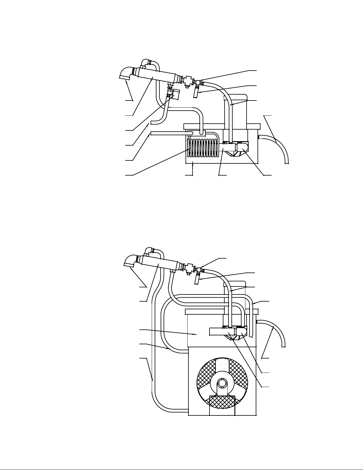
DIVERT VALVE
TO PROCESSED WAT E R HOSE
FROM PROCESS TANK
CONDENSER
WATER SOLENOID VALVE
WATER IN
WATER OUT
COOLING COIL
BE-15 "WATER-COOLED" DISTILLATE PIPING AND HOSE LAYOUT
PUMP RESERVOIR
ASPIRATOR
DIVERT VALVE
VACUUM HOSE
RECYCLED GLYCOL HOSE
ELBOW
TO PROCESSED WATER HOSE
FROM PROCESS TANK
CONDENSER
PUMP RESERVOIR
RADIATOR OUT
RADIATOR IN
VACUUM HOSE
BE-15C "AIR-COOLED" DISTILLATE PIPING AND HOSE LAYOUT
RETURN FROM RADIATOR
RECYCLED GLYCOL HOSE
ELBOW
ASPIRATOR
45
Page 46

BE-15/15C PARTS LIST: UNITS A91 THRU E92
Part # Description Notes
M100860 Aspirator
J101135 Barbed Hose Fitting For 1/2” hoses. 1/4” NPT threads.
J100634 Condenser Shell and tube heat exchanger.
J101108 Contactor
A101104 Cooling Coil
M100864 Cooling Coil Gasket
J101114 Divert Solenoid Valve Divert Valve and 120-volt solenoid coil.
J101885 Divert Valve only
A101179 Fan Blade assembly
J101558 Fan Motor 1/8 hp, TEAO motor for fan.
J101300 Fill Funnel
J101721 Fill or Drain Valve Ball valve in fill or drain piping.
J101104 Heater Band Exterior heater for Process Tank.
J101498 Heater Band Ceramic Terminal Caps
J102319 Heater Band Strap, lower with loop Holds bottom of Heater Band, has loop.
J101499 Heater Band Strap, upper Holds top of Heater Band in place.
A101103 Hose Kit
M100991 Insulation, bottom outside
M100988 Insulation, Heater Band
M100987 Insulation, Process Tank sides
M100990 Insulation, Process Tank top
J101130 Level Control Board
J101129 Level Control Probe Senses liquid level in Process Tank.
J101105 On/off Switch 120-volt coil, circuit breaker type.
J101140 Petcock Drain Plug
M100985 Plastic Skin, side
M100986 Plastic Skin, top
J101111 Pressure Relief Valve Protects Process Tank. Pops at 30 psi.
J101210 Radiator For Air-cooled units only.
J102467 Tape, 1/2” wide filament
J101131 TAS1
J101621 TAS2 – N/C 385° F Process Tank overtemp switch.
J101119 TAS3 – N/O 280° F Divert control switch.
J102149 TAS4 – N/C 180° F Distillate Piping overtemp switch.
J101139 Terminal Strip block
J100212 Vacuum Gage Measure vacuum from 0 to -28” Hg.
M100959 Vacuum/circulation Pump Elbow, Air-cooled Attaches to pump, hole for barb fitting.
J101514 Vacuum/circulation Pump Elbow, Water-cooled
M101626 Vacuum/circulation Pump Housing Outside cover for pump.
M100862 Vacuum/circulation Pump Housing Cover Inside cover for housing and impeller.
J102774 Vacuum/circulation Pump Housing O-ring O-ring to seal housing to housing cover.
A101678 Vacuum/circulation Pump Impeller Plastic impeller for pump, less shaft.*
M100958 Vacuum/circulation Pump Impeller Shaft Stainless steel impeller shaft for pump.
J101444 Vacuum/circulation Pump Motor 1/2 hp, 3450 rpm, 230V, TEFC, C-face.
J101256 Vacuum/circulation Pump Seal Seal for pump.
A101193 Vacuum/circulation Pump, Air-cooled Whole pump assembly with motor.
A101109 Vacuum/circulation Pump, Water-cooled
NO LONGER OFFERED
NO LONGER OFFERED
NO LONGER OFFERED
NO LONGER OFFERED
NO LONGER OFFERED
NO LONGER OFFERED
NO LONGER OFFERED
NO LONGER OFFERED
NO LONGER OFFERED
NO LONGER OFFERED
NO LONGER OFFERED
NO LONGER OFFERED
NO LONGER OFFERED
NO LONGER OFFERED
NO LONGER OFFERED
NO LONGER OFFERED
NO LONGER OFFERED
NO LONGER OFFERED
NO LONGER OFFERED
NO LONGER OFFERED
NO LONGER OFFERED
NO LONGER OFFERED
*Specify 3-1/2” diameter.
46
Page 47

BE-15/15C PARTS LIST: UNITS F92 AND NEWER
Part # Description Notes
M100860 Aspirator
J101135 Barbed Hose Fitting For 1/2” hoses. 1/4” NPT threads.
J100634 Condenser Shell and tube heat exchanger.
J101486 Contactor
A101104 Cooling Coil
M100864 Cooling Coil Gasket
J101892 Divert Solenoid Valve Divert Valve and 240-volt solenoid coil.
J101885 Divert Valve only
A101179 Fan Blade assembly
J101558 Fan Motor 1/8 hp, TEAO motor for fan.
J101300 Fill Funnel
J101721 Fill or Drain Valve Ball valve in fill or drain piping.
J101104 Heater Band Exterior heater for Process Tank.
J101498 Heater Band Ceramic Terminal Caps
J102319 Heater Band Strap, lower with loop Holds bottom of Heater Band, has loop.
J101499 Heater Band Strap, upper Holds top of Heater Band in place.
A101103 Hose Kit
M100991 Insulation, bottom outside
M100988 Insulation, Heater Band
M100987 Insulation, Process Tank sides
M100990 Insulation, Process Tank top
J101888 Level Control Board 240 volt, Series 26 version.
J101129 Level Control Probe Senses liquid level in Process Tank.
M100968 Level Control Probe Cover
J101890 On/off Switch 240-volt coil, circuit breaker type.
J101140 Petcock Drain Plug
M100985 Plastic Skin, side
M100986 Plastic Skin, top
J101111 Pressure Relief Valve Protects Process Tank. Pops at 30 psi.
J101210 Radiator For Air-cooled units only.
J102467 Tape, 1/2” wide filament
J101131 TAS1
J101621 TAS2 – N/C 385° F Process Tank overtemp switch.
J101119 TAS3 – N/O 280° F Divert control switch.
J102149 TAS4 – N/C 180° F Distillate Piping overtemp switch.
J101668 Terminal Strip
M100943 Top Panel Access Cover
J100212 Vacuum Gage Measure vacuum from 0 to -28” Hg.
M100959 Vacuum/circulation Pump Elbow, Air-cooled Attaches to pump, hole for barb fitting.
J101514 Vacuum/circulation Pump Elbow, Water-cooled
M101626 Vacuum/circulation Pump Housing Outside cover for pump.
M100862 Vacuum/circulation Pump Housing Cover Inside cover for housing and impeller.
J102774 Vacuum/circulation Pump Housing O-ring O-ring to seal housing to housing cover.
A101678 Vacuum/circulation Pump Impeller Plastic impeller for pump less shaft.*
M100958 Vacuum/circulation Pump Impeller Shaft Stainless steel impeller shaft for pump.
J101444 Vacuum/circulation Pump Motor 1/2 hp, 3450 rpm, 230V, TEFC, C-face.
J101256 Vacuum/circulation Pump Seal Seal for pump.
A101193 Vacuum/circulation Pump, Air-cooled Whole pump assembly with motor.
A101109 Vacuum/circulation Pump, Water-cooled
NO LONGER OFFERED
NO LONGER OFFERED
NO LONGER OFFERED
NO LONGER OFFERED
NO LONGER OFFERED
NO LONGER OFFERED
NO LONGER OFFERED
NO LONGER OFFERED
NO LONGER OFFERED
NO LONGER OFFERED
NO LONGER OFFERED
NO LONGER OFFERED
NO LONGER OFFERED
NO LONGER OFFERED
NO LONGER OFFERED
NO LONGER OFFERED
NO LONGER OFFERED
NO LONGER OFFERED
NO LONGER OFFERED
NO LONGER OFFERED
NO LONGER OFFERED
NO LONGER OFFERED
NO LONGER OFFERED
*Specify 3-1/2” diameter.
47
Page 48

Electrical Schematics
The schematics of the electrical components and wiring are presented in a ladder configuration. The proper
schematic for a particular BE unit is dependent upon its serial number.
Explanation of symbols and terms used in the schematics:
SWITCH
CIRCUIT
BREAKER
TAS3
NORMALLY OPEN
TEMP SWITCH
TAS2
SOL1
SOLENOID
C1
COIL FOR RELAY
OR CONTACTOR
C1-1
NORMALLY OPEN
CONTACTS
C1-4
R
LAMP (RED)
HEATER
MTR
MOTOR
GND
NORMALLY CLOSED
TEMP SWITCH
NORMALLY CLOSED
CONTACTS
BE-15/15C Electrical Schematic: Units D91 and older
BE-15 Water-cooled Electrical Schematic: Units E91 thru E92
BE-15C Air-cooled Electrical Schematic: Units E91 thru E92
BE-15 Water-cooled Electrical Schematic: Units F92 and newer
BE-15C Air-cooled Electrical Schematic: Units F92 and newer
48
GROUND
48
49
50
51
52
Page 49

R
O
H
C
T
I
W
S
P
M
E
T
R
E
V
O
H
C
T
I
W
S
T
E
S
E
R
R
E
T
A
E
H
K
N
A
T
T
O
M
P
M
U
P
M
U
U
C
A
V
L
O
R
T
N
O
C
L
E
V
E
L
&
H
E
C
V
T
I
L
A
W
V
S
D
R
I
E
O
T
N
R
E
E
L
V
I
O
D
S
3
2
3
4
0
5
3
S
A
T
1
3
BOARD.
*MOST UNITS
RETROFITTED
WITH SERIES 16
LEVEL CONTROL
2
2
-
1
C
7
1
R
C
R
R
E
T
A
E
H
4
1
B
P
5
1
-
1
R
C
1
6
1
-
1
C
1
2
2
-
2
C
9
)
d
R
e
p
E
p
L
i
L
u
I
q
H
e
C
f
i
(
1
1
1
-
2
C
1
3
*
L
E
V
E
L
W
O
L
2
1
2
S
A
T
1
1
1
R
T
M
0
1
2
-
1
R
C
1
3
3
1
1
S
0
1
3
2
L
O
S
4
1
1
C
3
S
A
T
3
1
W
3
2
C
3
1
H
C
T
I
W
S
F
F
O
/
N
O
UNITS D91 AND OLDER
BE-15/15C ELECTRICAL SCHEMATIC
N
2
L
1
L
D
N
G
49
Page 50

R
O
T
O
L
M
O
P
R
E
T
A
E
H
K
N
A
T
R
M
T
U
N
P
O
M
C
U
L
U
E
V
C
E
A
L
V
H
C
T
I
W
S
F
F
O
/
N
O
E
R
V
E
L
T
A
A
V
W
D
I
G
O
N
I
N
L
E
O
L
O
O
C
S
&
H
E
C
V
T
I
L
A
W
V
S
D
R
I
E
O
T
N
R
E
E
L
V
I
O
D
S
N
2
2
L
L
1
1
2
-
1
C
7
R
E
T
A
E
H
6
1
-
1
C
1
L
1
N
2
L
1
2
-
2
C
9
1
R
T
M
2
L
1
L
8
1
-
2
C
1
1
L
L
1
1
1
2
E
B
O
R
P
O
T
H
L
G
D
N
U
O
R
G
K
N
A
T
O
T
2
2
N
.
M
C
.
O
N
C
4
2
8
8
1
1
1
L
O
S
1
1
R
S
C
4
0
2
1
.
O
.
N
4
S
A
T
2
S
A
T
R
5
2
1
L
1
5
1
1
1
S
A
T
2
C
C
3
3
1
1
BE-15 WATER-COOLED
ELECTRICAL SCHEMATIC
8
1
2
L
O
S
4
1
3
S
A
T
3
1
UNITS E91 THRU E92
2
N
1
L
D
L
N
G
50
Page 51

R
O
T
O
M
L
O
R
E
T
A
E
H
K
N
A
T
P
R
M
T
U
R
O
T
O
M
N
A
F
N
P
O
M
C
U
L
U
E
C
V
A
E
V
L
H
C
T
I
W
S
F
F
O
/
N
O
&
H
E
C
V
T
I
L
A
W
V
S
D
R
I
E
O
T
N
R
E
E
L
V
I
O
D
S
N
2
L
1
2
-
1
C
2
-
2
C
7
R
E
T
A
E
H
2
R
T
M
6
1
-
1
C
1
L
1
1
-
2
C
N
2
L
1
1
9
1
R
T
M
2
L
1
L
8
1
1
L
L
1
1
2
E
B
O
R
P
O
T
L
H
G
D
N
U
O
R
G
K
N
A
T
O
T
2
2
N
4
2
.
C
.
N
.
O
.
M
N
O
C
4
2
8
1
1
1
R
S
C
0
1
4
S
A
T
2
S
A
T
R
5
2
1
L
1
2
1
C
C
3
1
BE-15C AIR-COOLED
8
1
2
L
O
S
4
1
3
S
A
3
T
1
UNITS E91 THRU E92
ELECTRICAL SCHEMATIC
1
2
N
L
D
L
N
G
51
Page 52

R
O
T
O
M
L
O
P
R
E
T
A
E
H
K
N
A
T
R
M
T
U
N
P
O
M
C
U
L
U
E
C
V
A
E
V
L
H
C
T
I
W
S
F
F
O
/
N
O
E
R
V
E
L
T
A
A
V
W
D
I
G
O
N
I
N
L
E
O
L
O
O
C
S
&
H
E
C
V
T
I
L
A
W
V
S
D
R
I
E
O
T
N
R
E
E
L
V
I
O
S
D
2
2
L
1
3
-
1
C
7
R
E
T
A
E
H
6
1
-
1
C
1
L
1
2
L
L
1
1
4
-
1
C
9
1
R
T
M
8
2
-
1
C
1
1
L
L
1
1
2
2
D
N
U
O
R
G
K
N
A
T
O
T
.
2
G
L
1
L
L
E
B
O
R
P
O
T
.
M
C
.
O
N
C
L
C
O
4
S
A
T
2
1
2
S
A
T
2
L
1
8
2
L
O
S
3
S
A
T
ELECTRICAL SCHEMATIC
UNITS F92 AND NEWER
1
4
1
3
1
8
1
1
L
O
S
1
1
R
S
C
6
2
.
O
.
N
0
1
5
2
1
L
1
R
1
S
A
T
1
C
5
1
3
1
BE-15 WATER-COOLED
2
1
L
D
L
N
G
52
Page 53

R
O
T
O
M
L
O
R
E
T
A
E
H
K
N
A
T
P
R
M
T
U
R
O
T
O
M
N
A
F
N
P
O
M
C
U
L
U
E
C
V
A
E
L
V
H
C
T
I
W
S
F
F
O
/
N
O
E
H
V
C
L
T
A
I
V
W
D
S
I
R
O
E
N
T
E
L
R
E
O
V
S
I
D
&
2
2
L
1
3
-
1
C
7
R
E
T
A
E
H
6
1
-
1
C
1
L
1
2
L
L
1
1
4
-
1
C
9
1
2
R
R
T
T
M
M
8
2
-
1
C
1
1
L
L
1
1
2
2
D
N
U
O
R
G
K
N
A
T
O
T
2
L
1
L
L
L
E
B
O
R
P
O
T
.
G
C
O
1
2
.
C
.
M
N
O
C
0
1
4
S
A
T
2
S
A
T
2
L
1
8
1
2
L
O
1
S
C
1
1
R
S
C
R
6
2
.
O
.
N
5
2
1
L
1
BE-15C AIR-COOLED
3
S
A
T
UNITS F92 AND NEWER
ELECTRICAL SCHEMATIC
4
1
3
1
1
2
L
D
L
N
G
53
Page 54

Notes
Finish Thompson Inc.
921 Greengarden Road
Erie, PA 16501-1591 USA
Ph. 814-455-4478
Fax 814-455-8518
Technical Service Hotline
800-888-3743
or
Email: techservice@finishthompson.com
10-17-08-kc
Updated 5-21/09
54
 Loading...