

Page 1
AK / AV 4 & 5 SERIES
Metallic Vertical Centrifugal Pumps
Installation and Maintenance Instructions
ASSEMBLY
PUMPS WITH MOTORS
1. No assembly required. Simply unpack the pump and motor
and examine for any signs of shipping damage. If damage is
detected, save the packaging and notify the carrier immediately.
2. To install the pump into the system, follow the installation
instructions provided.
PUMPS WITHOUT MOTORS
1. Unpack the pump and any supplied accessories and examine
for damage. If damage is detected, save the packaging and
notify the carrier immediately.
2. Lay the motor on its side. Install the slinger ring (item 2)
onto the motor shaft. After coating the motor shaft threads
with a thread lube, thread the pump shaft (item 8) onto the
motor shaft about 3 full turns. Install the four set screws
(item 6) in the motor end of the pump shaft, but do not
tighten.
3. Gently place the motor on the fan cover so the pump shaft
points straight up. Install the mounting plate (item 1) with
the four locating tabs (these are welded on one side of the
plate) facing the motor and locating on the raised motor face.
Slide column assembly (item 7) over the pump shaft and attach to the motor with the four mounting bolts, flat washers
and lock washers (items 5,3, 4) going through the column
flange and the mounting plate.
4. Lay the pump on its side and remove the fan cover from the
motor.
8. On AK/AV 4 models, spin the fan blade and visually check
to make sure all four impeller fins are not rubbing and are
straight in relationship to the back head section of the column
assembly. Gently adjust the fins if necessary.
9. Install the impeller housing (item 16) (without the o-ring) and
hold in place with your hand. Spin the fan blade while listening and feeling for impeller rubbing. Pump shaft adjustment
can be made if necessary.
10. Replace the motor fan cover and gently place the pump on the
motor fan cover.
11. Clean the o-ring sealing area on the back head section of the
column assembly and the impeller housing. Lubricate the
o-ring (item 10) with a compatible lubricant.
12. Install the impeller housing and v-clamp (item 11). Impeller
housings with the discharge attached need to be inserted into
the hole in the mounting plate and visually aligned with the
column assembly. Snug the nut on the v-clamp.
13. The alignment for the discharge can be adjusted by tapping
the impeller housing discharge left or right with a rubber mallet. Visually check that the discharge is parallel to the column
assembly and it goes through the mounting plate straight.
14. Once the discharge alignment is correct the v-clamp nut can be
tightened.
15. Insert a 1/2” socket into the suction and spin the impeller to
check clearances.
16. Install the pump into the system following the installation
instructions provided.
INSTALLATION
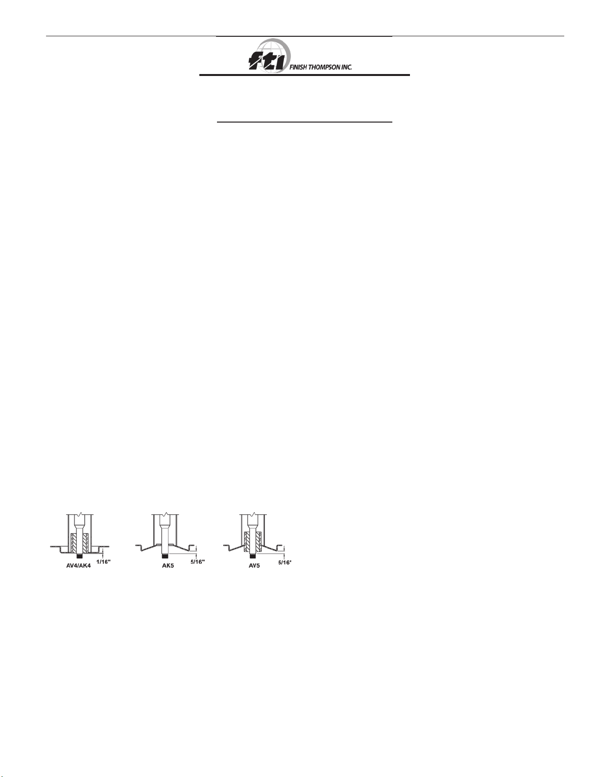
Figure 1
5. Holding the motor fan, adjust the pump shaft by threading
clockwise or counterclockwise until the pump shaft shoulder
is set correctly (see figure 1).
6. Tighten the setscrews in the pump shaft through the access
hole at the motor end of the column assembly.
7. After applying a thread lube, thread the impeller (item 12) on
until it bottoms out on the pump shaft shoulder. Install the
5/16 bolt, washer and lock washer (items 15, 13, 14) in the
impeller end of the pump shaft.
MOUNTING:
1. Base plate must be securely fastened so that there is no vibration
when the pump is running.
2. Align the piping with the pump ports. Do not connect the piping
until it is aligned properly and supported independently. Do not
pull the piping in line with the pump or support the piping with
the pump.
3. A valve should be installed in the discharge line. During initial
operation of the pump, determine the power consumed. If
necessary, throttle back the flow until the pump draws the
rated horsepower of the motor.
1
Page 2
PIPING TO AND FROM THE PUMP:
Figure 2
Always support the piping near the pump to minimize stress
and strain.
Minimize frictional losses by increasing the piping size by one
diameter.
Use a minimum number of bends, keeping any bends a mini-
mum distance of ten pipe diameters from the pump.
Install a valve on the discharge line to control the flow. Place
the valve within a distance of ten pipe diameters from the
pump.
Ensure that the pump is leak free.
Maintain a flooded suction at all times. Use a float switch to turn
off the pump at low level.
CAUTION: Suction prime must be maintained at all times.
Running the pump dry will cause damage to the pump
components. To protect the pump if prime is lost, use a
pressure switch on the discharge or a motor power monitor
to monitor motor current draw.
Note: AK4 & AK5 can be run dry without damage since they have no
lower bushing.
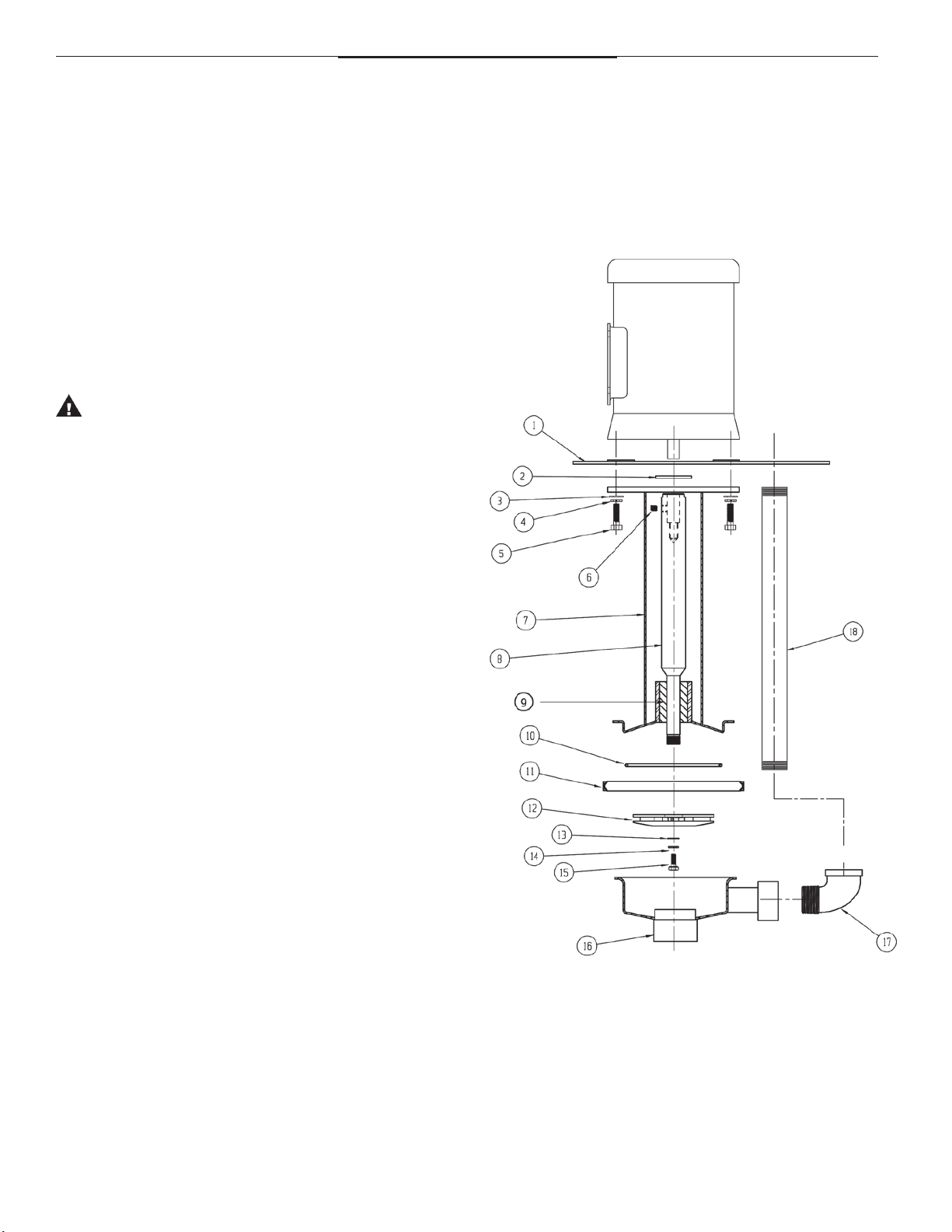
AK/AV Parts Drawing
ELECTRICAL CONNECTIONS:
1. Perform the motor wiring according to NEC requirements and
local electrical codes.
2. Wire the motor for clockwise rotation when facing the fan end
of the motor.
3. To verify correct motor rotation:
a. Install the pump into the system.
b. Fully open the suction and the discharge valves.
c. Allow fluid to flow into the pump. Do not allow the pump
to run dry, as this will cause damage to pump components.
d. Jog the motor (allow it to run for only one to two seconds)
and observe the rotation of the motor fan. Refer to the
directional arrow on the pump if needed.
Note: A pump running backwards will pump, but a greatly reduced
flow and pressure.
OPERATION
1. Partially open the discharge valves.
2. Start the pump and verify liquid is flowing. If there is no liquid
flow, refer to the “Troubleshooting” section of these instructions.
3. Adjust the flow rate and pressure by regulating the discharge
valve.
2
Page 3

AK/AV 4 & 5 PARTS LIST
3
Page 4

TROUBLESHOOTING
NO OR INSUFFICIENT FLOW:
1. No liquid in the sump
2. Closed valve.
3. Viscosity too high.
4. Discharge head higher than anticipated.
5. Suction too close to the bottom of the sump.
INSUFFICIENT PRESSURE:
1. Air or gasses in liquid.
2. Discharge head higher than anticipated.
EXCESSIVE POWER CONSUMPTION:
1. Head lower than rating.
2. Specific gravity or viscosity of liquid is too high.
EXCESSIVE VIBRATION:
1. Loose piping or bolts.
2. Suction too close to the bottom of the sump.
WARRANTY
Finish Thompson, Inc (manufacturer) warrants this pump product to be
free of defects in materials and workmanship for a period of180 days
from date of purchase by original purchaser. If a warranted defect,
which is determined by manufacturer’s inspection, occurs within this
period, it will be repaired or replaced at the manufacturer’s option,
provided (1) the product is submitted with proof of purchase date and
(2) transportation charges are prepaid to the manufacturer. Liability
under this warranty is expressly limited to repairing or replacing the
product of parts thereof and is in lieu of any other warranties, either
expressed or implied. This warranty does apply only to normal wear of
the product or components. This warranty does not apply to products
or parts broken due to, in whole or in part, accident, overload, abuse,
chemical attack, tampering, or alteration. The warranty does not apply
to any other equipment used or purchased in combination with this
product.
The manufacturer accepts no responsibility for product damage or
personal injuries sustained when the product is modified in any way. If
this warranty does not apply, the purchaser shall bear all cost for labor,
material and transportation.
Manufacturer shall not be liable for incidental or consequential damages
including, but not limited to process down time, trans-portation costs,
costs associated with replacement or substi-tution products, labor
costs, product installation or removal costs, or loss of profit. In any
and all events, manufacturer’s liability shall not exceed the purchase
price of the product and/or accessories.
CHEMICAL REACTION DISCLAIMER
The user must exercise primary responsibility in selecting the product’s
materials of construction, which are compatible with the fluid(s) that
come(s) in contact with the product. The user may consult Finish
Thompson, Inc. (manufacturer) and a manufacturer’s representative/
distributor agent to seek a recommendation of the product’s material of
construction that offers the optimum available chemical compatibility.
However neither manufacturer nor agent shall be liable for product
damage or failure, injuries, or any other damage or loss arising out
of a reaction, interaction or any chemical effect that occurs between
the materials of the product’s construction and fluids that come into
contact with the product’s internals.
ORDERING SPARE PARTS
Spare parts can be ordered from your local distributor. Always refer
to the pump model number to avoid error.
OTHER FINISH THOMPSON PRODUCTS
Finish Thompson manufactures a diverse range of pumps including
drum/barrel fluid transfer, plastic or metallic magnetic drive and
plastic or stainless steel mechanical sealed centrifugal pumps. For
more information on these products visit our web site at www.
finishthompson.com or contact your local distributor.
Call our Technical Service Hot Line, 1-800-888-3743, if you have any
questions regarding product operation or repair.
SERVICE 800-888-3743
J103017, Rev7, 4.30.12
4
 Loading...