

Page 1
AC6/6H & AC8/8H
Horizontal Metric Models
ASSEMBLY, INSTALLATION AND
OPERATION MANUAL
Part No. 108203
Page 2
Page 3

TABLE OF CONTENTS
Description Page Number
Model/Serial Number ................................................................................................. 4
Important Notice ........................................................................................................ 4
Chemical Reaction Disclaimer .................................................................................... 4
Safety Precautions ..................................................................................................... 4-5
Capabilities ................................................................................................................ 5
Maximum Working Pressure & Temperature ....................................................... 5
Solids ................................................................................................................. 5
Minimum Flow Rate ........................................................................................... 5
Section 1 - Assembly ................................................................................................. 6
Section II - Installation ................................................................................................ 7
Section III - Start-up & Operation ................................................................................ 7-8
Start-up ............................................................................................................. 7
Shutdown ........................................................................................................... 7
Flush Systems .................................................................................................... 8
Section IV - Maintenance ........................................................................................... 8
Disassembly ....................................................................................................... 8
Reassembly ........................................................................................................ 9
AC6/AC6H Exploded View Diagram ..................................................................... 10
AC6/AC6H Parts List ........................................................................................... 10
AC8/AC8H Exploded View Diagram...................................................................... 11
AC8AC8H Parts List ............................................................................................. 11
Section V - Troubleshooting ........................................................................................ 12
Section VI - Warranty ................................................................................................. 12
For factory assistance with repairs or maintenance, call 1-800-888-3743.
FTI Contacts:
Tech Service: 800-888-3743 or techservice@finishthompson.com
Order Fax: 814-459-3460 or 814-455-8518
Sales: 814-455-4478; 800-934-9384 (U.S. & Canada)
Page 4

Model Number and Serial Number
Record the model number and serial number below for future reference. This is important information when ordering replacement
parts or when technical assistance is required. The numbers are found on a label located on the motor adapter.
MODEL NUMBER ___________________________
SERIAL NUMBER __________________________
Chemical Reaction Disclaimer
The user must exercise primary responsibility in selecting the products materials of construction, which are compatible with the
fluid(s) that come(s) in contact with the product. The user may consult Finish Thompson, Inc. (manufacturer) and a manufacturer’s
representative/distributor agent to seek a recommendation of the products material of construction that offers the optimum available
chemical compatibility.
However neither manufacturer nor agent shall be liable for product damage or failure, injuries, or any other damage or loss arising
out of a reaction, interaction or any chemical effect that occurs between the materials of the products construction and fluids that
come into contact with the products components.
Safety Precautions
WARNING: READ THIS MANUAL COMPLETELY BEFORE INSTALLING AND OPERATING THIS UNIT. FAILURE TO FOLLOW THESE
PRECAUTIONS CAN RESULT IN SERIOUS INJURY OR DEATH.
WARNING: Hot surfaces. This pump is capable of handling liquids with temperatures as high as 300F (149C). This may
cause the outer areas of the pump to become hot as well and could cause burns.
WARNING: Rotating Parts. This pump has components that rotate while in operation. Follow local safety standards for locking
out the motor from the power supply during maintenance or service.
WARNING: Chemical Hazard. This pump is used for transferring many types of potentially dangerous chemicals. Always wear
protective clothing, eye protection and follow standard safety procedures when handling corrosive or personally harmful materials.
Proper procedures should be followed for draining and decontaminating the pump before disassembly and inspection of the pump.
There may be small quantities of chemicals present during inspection.
WARNING: Never run pump at less than minimum flow or with the discharge valve closed. This could lead to pump failure.
WARNING: The pump and associated components are heavy. Failure to properly support the pump during lifting and move-
ment could result in serious injury or damage to the pump and components.
CAUTION: This pump should never be started without liquid in the casing. IT CANNOT BE RUN DRY WITHOUT CAUSING DAMAGE
TO THE PUMP. It is recommended that run dry protection be used. Optional electronic power monitors are available to help protect
against run dry.
CAUTION: Never start or operate with a closed suction valve.
WARNING: Operation without priming or against a closed discharge valve can result in high temperatures that can result in
injury or damage to pump components.
CAUTION: Always provide adequate NPSHa (net positive suction head available). It is recommended to provide at least 2 feet
(61 cm) above the NPSHr (net positive suction head required).
CAUTION: If pump is used on variable speed drive, do not exceed the frequency for which the pump was designed (for example, if the pump is a 50 Hz model, do not exceed 50 Hz).
4
Page 5

Safety Precautions for ATEX Pumps
CAUTION: Proper o-ring material must be chosen for the fluid being pumped. Improper material selection could lead to swelling
and be a possible source of leaks. This is the responsibility of the end user.
WARNING: The pump must be checked for leaks on a regular basis. If leaks are noticed, the pump must be repaired or re-
placed immediately.
WARNING: The pump must be cleaned on a regular basis to avoid dust buildup greater than 5 mm.
WARNING: ATEX pumps must use a power monitor, flow switch, pressure switch or similar device to help protect against run-
ning dry or closed discharge valve. Any of these conditions could lead to a rise in surface temperature of the pump.
WARNING: The surface temperature of AC6 & 8 Series pumps is completely dependent on operating conditions. Pump will
transfer heat from the piping system, motor and fluid. These items must be considered as a system when assessing an ATEX application.
WARNING: In the event of a motor bearing failure, the ceramic stationary seal face will protect the pump shaft from making
metal on metal contact until the power monitor shuts the pump down. Pump must be fitted with a power monitor that will shut down
the pump within 3 seconds of a motor bearing failure.
AC6 & 8 Capabilities
Maximum Working Pressure: AC6 - 100psi (6.9 bar)
AC8 - 120psi (8.3 bar)
Maximum Temperature: 300°F (149°C)
NOTE: Maximum temperature is application dependent. Consult a chemical resistance guide or the chemical manufacturer for chemical compatibility and
temperature limits.
Solids: Maximum particle size is 100 microns for slurries and 1/64 (0.4 mm) for occasional solids.
Maximum hardness is 80 HS. Maximum concentration is 10% by weight.
NOTE: If solids are being pumped, it is recommended that the pump have a Silicon Carbide mechanical seal. Pumping solids may lead to increased wear.
Minimum Allowable Flow Rate: AC6 = 10 gpm (2.3 m3/hr)
3
3
3
/hr)
/hr)
/hr)
AC6H = 3 gpm (0.7 m
AC8 = 20 gpm (4.5 m
AC8H = 5 gpm (1.1 m
5
Page 6

AC6 & 8 Assembly, Installation and Operation
Unpacking and Inspection
• Unpack the pump and examine for any signs of shipping damage.
• If damage is detected, save the packaging and notify the carrier immediately.
Section I - Assembly
Tools Required: Metric box wrench set & metric deep well socket set
- Pumps with Motors
1. No assembly required. Unpack the pump and motor and examine for any signs of shipping damage. If damage is
detected, save the packaging and notify the carrier immediately.
2. Proceed to the “Installation” section of these instructions.
- Pumps without Motors - 90, 100/112, 132 & 160 frame with B5 flange: All motors must have motor feet.
Very Important: Do not remove shipping plug located in suction port of the pump until the pump is completely assembled onto the
motor.
1. Unpack the pump and examine for any signs of shipping damage. If damage is detected, save the packaging and
notify the carrier immediately.
2. Insert key into motor keyway. (See Figure 1). Visually determine key location in pump end. Align keyway slots on motor shaft and
pump impeller sleeve. Slide pump assembly over the motor shaft until the pump motor adapter (item 8 for AC6 or 22 for AC8) is
completely seated over the motor rabbet. Install 4 bolts with flat washers and lock washers (items 9, 10 &
11 for AC6 or 19, 20 & 21 for AC8) through the face of the motor & into the motor adapter. Securely tighten bolts using
the torque specifications in the table below.
3. Lubricate o-ring of self-sealing bolt (item 6) with suitable, compatible lubricant. Insert self-sealing bolt through shipping plug and
into the eye of the impeller using a deep well socket. Insert a screwdriver into the motor fan to prevent motor shaft from rotating.
Securely tighten bolt using the torque specifications in the table below.
4. Remove the shipping plug from the suction port.
5. Rotate the motor fan by hand and check for impeller rubbing. If the impeller rubs, verify that the self-sealing bolt is properly
installed.
6. Proceed to the “Installation” section of these instructions.
Flange hole thread size:
Motor Frame 90 B5 = M10 x 1.5
Motor Frame 100/112/132 B5 = M12 x 1.75
Motor Frame 160 B5 = M18 x 2.5
Torque bolts to the following:
Motor Frame 90 frame B5 (M10) = 240 in-lb (27.1 N-m)
Motor Frame 100/112/132 B5 (M12) = 480 in-lb (54.3 N-m)
Torque impeller bolt to the following:
Motor Frame 90 frame B5 (M8) = 130 in-lb (14.7 N-m)
Motor Frame 100/112 B5 (M10) = 240 in-lb (27.1 N-m)
Motor Frame 132 B5 (M12) = 480 in-lb (54.3 N-m)
Motor Frame 160 B5 (M16) = 118 ft-lb (160.3 N-m)
Fig 1
6
Page 7

Section II - Installation
Pump motor base should be securely fastened to a solid foundation.
CAUTION: The NPSH available to the pump must be greater than the NPSH required. NPSH available should be two feet (.6
meters) greater than NPSH required.
• Install the pump as close to the suction source as possible.
• Support the piping independently near the pump to eliminate any strain on the pump casing. In addition, the piping should be
aligned to avoid placing stress on the pump casing.
• The suction side of the pump should be as straight and short as possible to minimize pipe friction.
• The suction line should not have any high spots. This can create air pockets that can reduce pump performance. The suction
piping should be level or slope slightly upward to the pump.
• If flexible hose is preferred over pipe, use a reinforced hose rated for the proper temperature, pressure and is chemically resistant
against the fluid being pumped.
• The suction valve must be completely open to avoid restricting the suction flow.
• When installing pumps with flanges, we recommend use of low seating stress gaskets such as Gore-Tex or Gylon (expanded
PTFE).
Motor/Electrical
Install the motor according to NEC requirements and local electrical codes. The motor should have an overload protection circuit.
Wire the motor for clockwise rotation when facing the fan end of the motor.
CAUTION: Do not operate the pump to check rotation until the pump is full of liquid.
Check all electrical connections with the wiring diagram on the motor. Make sure the voltage, frequency, phase and amp draw
comply with the supply circuit.
To verify correct rotation of the motor:
1. Install the pump into the system.
2. Fully open the suction and discharge valves.
3. Allow fluid to flow into the pump. Do not allow the pump to run dry.
4. Jog the motor (allow it to run for 1-2 seconds) and observe the rotation of the motor fan. Refer to the directional arrow label on
pump housing if necessary.
NOTE: A pump running backwards will pump but at a greatly reduced flow and pressure.
Section III - Start-up and Operation
CAUTION: Do not run the pump dry. This pump should never be started without liquid in the casing. The fluid being transferred
by the pump lubricates the pump components. Even short periods of running the pump dry could damage the pump. It is recommended that run dry protection is used. Optional electronic power monitors are available to help protect against run dry.
1. This pump must be filled from a flooded suction tank (gravity) or primed with liquid from an outside source. The AC6 & 8 pumps
are not self-priming.
2. Open the inlet (suction) and discharge valves completely and allow the pump to fill with liquid.
3. Close the discharge valve.
4. Turn the pump on. Slowly open the discharge valve. Adjust the flow rate and pressure by regulating the discharge valve. Do not
attempt to adjust the flow with the suction valve.
Shutdown
1. Use the following procedure to shutdown the pump.
2. Slowly close the discharge valve.
3. Turn off the motor.
4. Close the suction valve.
7
Page 8
Flush Systems
CAUTION: Some fluids react with water; use compatible flushing fluid.
1. Turn off the pump.
2. Completely close the suction and discharge valves
3. Connect flushing fluid supply to flush inlet valve.
4. Connect flushing fluid drain to flush drain valve.
5. Open flushing inlet and outlet valves. Flush system until the pump is clean.
Section IV – Maintenance
Recommended maintenance schedule
The recommended maintenance schedule depends upon the nature of the fluid being pumped and the specific application. If the
pump is used on a clean fluid, it is recommended that the pump be removed from service and examined after six months of operation or after 2,000 hours of operation. If the pump is used on fluids with solids, high temperatures or other items that could cause
accelerated wear, then this initial examination should be sooner.
After the initial examination of the internal components and wear items are measured, a specific maintenance schedule can be
determined. For best results, it is recommended that the pump be removed from service annually for examination.
Disassembly
WARNING: Rotating Parts. This pump has components that rotate while in operation. Follow local safety standards for locking
out the motor from the power supply during maintenance or service.
WARNING: Chemical Hazard. This pump is used for transferring many types of potentially dangerous chemicals. Always wear
protective clothing, eye protection and follow standard safety procedures when handling corrosive or personally harmful materials.
Proper procedures should be followed for draining and decontaminating the pump before disassembly and inspection of the pump.
There may be small quantities of chemicals present during inspection.
WARNING: Stop the pump, lock out the motor starter, close all the valves that are connected to the pump, and drain/decontaminate the pump.
WARNING: The pump must be thoroughly flushed of any hazardous materials and all internal pressure relieved prior to opening
the pump. Allow the pump to reach ambient temperatures prior to performing maintenance.
Seal Replacement & Disassembly
1. Disconnect power. Remove electrical wiring.
2. Close the suction and the discharge valves. Disconnect the piping. Remove any mounting bolts.
3. For AC6 pumps - Remove the v-clamp (item 2) and the impeller housing (item 1), first apply a thread lubricant to the threaded rod
portion of the v-clamp then remove the nut. Remove the v-clamp, the housing, and the o-ring (item 3).
For AC8 pumps - Remove the 8 housing bolts and all the hardware (items 15, 16, 17, 18). Remove the impeller housing (item 1)
and the o-ring (item 3).
4. Place a screwdriver in the motor fan to prevent rotation and remove the self-sealing bolt (item 6).
Note: Do not reuse the self-sealing bolt.
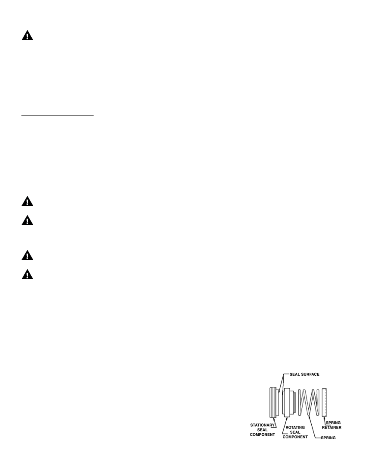
5. Remove impeller (item 4), rotating seal component, seal spring and seal spring retainer.
Discard seal components after removal. (See Figure 2).
6. Remove back head assembly (item 7) and press out the stationary seal component.
Discard stationary seal component after removal.
8
Fig 2
Page 9

Reassembly
1. Lubricate the rubber portion of the new stationary seal (item 5) with P-80 (or equivalent) or use soapy water. Do not use
petroleum products to lubricate the rubber.
Note: Keep the polished surface of the seal face clean. Use a piece of cardboard to protect the seal while pressing against the stationary face.
2. Press the stationary seal into the seal seat of the back head assembly so that the seal surface points away from the motor face.
Place the back head into the motor adapter.
3. Place the spring retainer and seal spring onto the impeller sleeve.
4. Lubricate the inside diameter of the rotating seal component with P-80 (or equivalent) or soapy water and press it over the
impeller sleeve (item 4) with the rotating face pointed away from the impeller as shown in Figure 2 (towards the stationary face).
5. Insert key into the motor keyway. Visually determine key location in impeller sleeve. Align keyway slots on motor shaft and
impeller sleeve. Slide impeller assembly over the motor shaft. Lubricate o-ring of new self-sealing bolt (item 6) with suitable,
compatible lubricant. Insert self-sealing bolt into the eye of the impeller using a deep well socket. Insert a screwdriver into the
motor fan to prevent motor shaft from rotating. Tighten the bolt to 12-ft lbs.
6. Place impeller housing (item 1) over back head (item 7) and o-ring (item 3) and make sure discharge is in the correct orientation
(usually 12 o’clock).
7. For AC6 pumps - Place the v-clamp (item 2) over the impeller housing, back head, and the
mounting plate (item 14). Make sure the discharge is level and in the correct
orientation. (See Figure 3). Tighten the nut on the v-clamp. Firmly tap
the v-clamp with a mallet in several spots, and then retighten the nut.
For AC8 pumps - Insert the mounting bolts with flat washer (items 15 &16) through the
impeller housing (item 1), the back head (item 7), and the mounting plate
(item 14), and tighten with the correct hardware (items 15, 17, & 18).
Fig 3
8. Rotate the motor fan by hand and check for impeller rubbing. If the impeller rubs, verify that the self-sealing bolt is properly
installed.
9. Reinstall the pump into the system.
9
Page 10
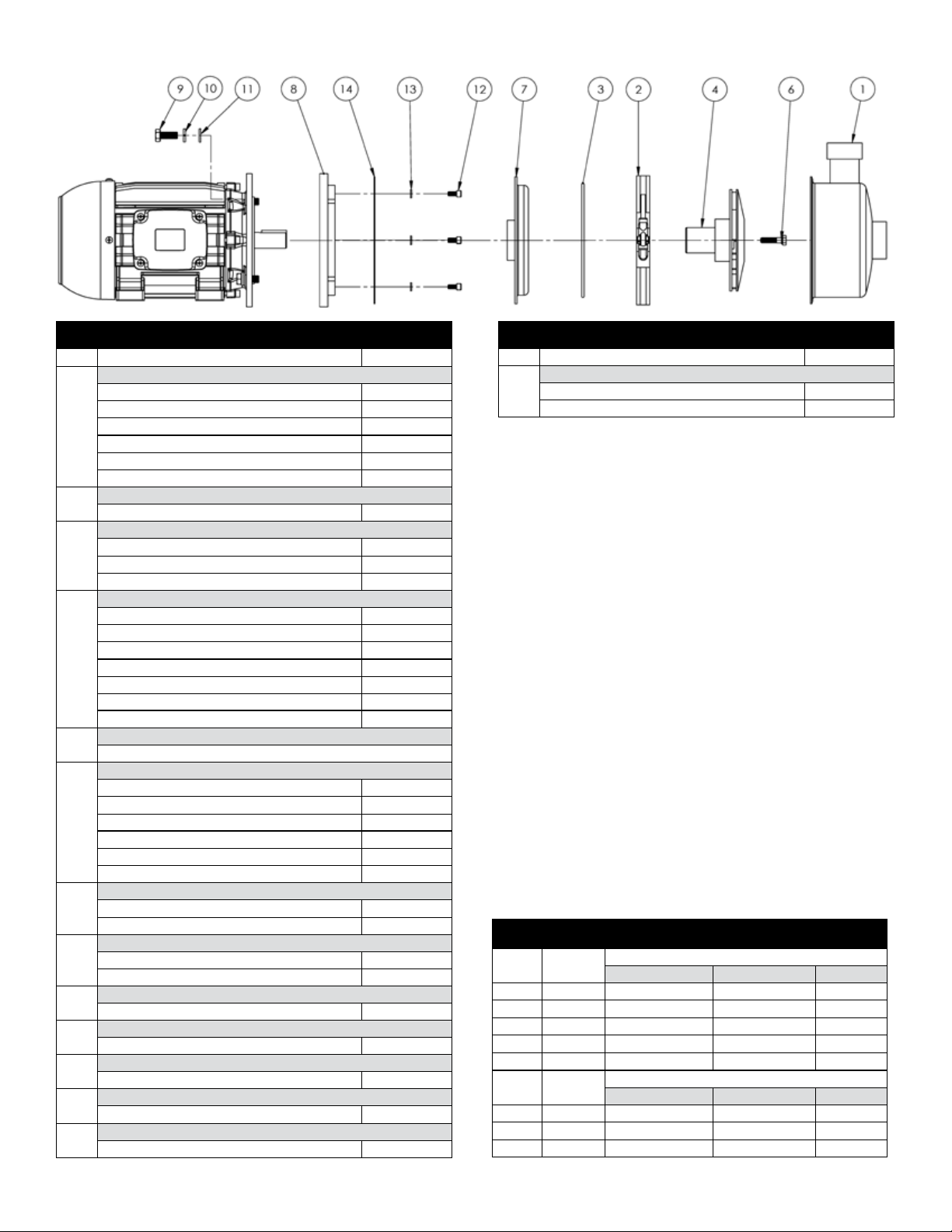
AC6/AC6H Exploded View
AC6-AC6H Spare Parts
Item Description Part No.
Impeller Housing
AC6SJS - 1-1/2" x 1-1/4" FBSP A102184-3
AC6SJS - 2" X 1-1/2" FBSP A102184-4
AC6HJS - 1-1/4" x 3/4" FBSP A102232-1
1
AC6SJS - 1-1/2" x 1-1/4" FNPT A102184-1
AC6SJS - 2" X 1-1/2" FNPT A102184-2
AC6HJS - 1-1/4" x 3/4" FNPT A102232
V Clamp
2
304 stainless steel J103090
Housing O-Ring
FKM J103084
3
EPDM J103085
PTFE encapsulated silicone J103257
Impeller 316 Stainless Steel
5.25" Standard w/ IEC 90 B5 (AC6) 106185-2
5.75" Standard w/ IEC 90 B5 (AC6) 106185-1
6.00" Standard w/ IEC 90 B5 (AC6) 106185
4
5.25" Standard w/ IEC 100/112 B5 (AC6) 105981-2
5.75" Standard w/ IEC 100/112 B5 (AC6) 105981-1
6.00" Standard w/ IEC 100/112 B5 (AC6) 105981
6.25" High Head w/ IEC 90 B5 (AC6H) A102735-4
Mechanical Seal (Not Shown)
5
See AC6 Seal Options Table on this page
Impeller Bolt w/ O-ring
with FKM for AC6/AC6H IEC 90 B5 107885
with EPDM for AC6/AC6H IEC 90 B5 107886
with PTFE for AC6/AC6H IEC 90 B5 107887
6
with FKM for AC6 IEC 100/112 B5 107251
with EPDM for AC6 IEC 100/112 B5 107252
with PTFE for AC6 IEC 100/112 B5 107268
Backhead
IEC 90 B5 316 stainless steel A102677-3
7
IEC 100/112 B5 316 stainless steel A102677-4
Cast Iron Motor Adapter
AC6SJS 106184
8
AC6HJS 106022
Hex Head Cap Screw (4 req'd.)
9
Customer to supply -
Lock Washer (4 req'd.)
10
Customer to supply -
Flat Washer (4 req’d)
11
Customer to supply -
Socket Head Cap Screw (4 req’d)
12
1/4” stainless steel J103396
Lock Washer (4 req’d)
13
1/4” stainless steel J100672
AC6-AC6H Spare Parts - cont.
Item Description Part No.
Mounting Plate
IEC 90 B5 J103389-2
14
IEC 100/112 B5 105993
AC6-AC6H Mechanical Seal Options
Option
D01 J103556 Carbon Ceramic FKM
D02 J103557 Carbon Ceramic EPDM
D04 J103560 Carbon Ceramic Kalrez®
D05 J103558 Silicon Carbide Silicon Carbide FKM
D06 J103559 Silicon Carbide Silicon Carbide EPDM
Option
D01 105995 Carbon Ceramic FKM
D02 106395 Carbon Ceramic EPDM
D05 107940 Silicon Carbide Silicon Carbide FKM
Part
Number
Part
Number
Rotating Face Stationary Face Elastomer
Rotating Face Stationary Face Elastomer
Seals for 90 Frame Only
Seals for 100/112 Frame Only
10
Page 11

AC8/AC8H Exploded View
AC8-AC8H Spare Parts
Item Description Part No.
Impeller Housing
AC8HJS - 1-1/4" x 3/4" FBSP A102528-1
AC8SJS - 2" x 1-1/2" FBSP A102747-4
AC8SJS - 2-1/2" x 2" FBSP A102747-3
1
AC8HJS - 1-1/4" x 3/4" FNPT A102528
AC8SJS - 2" x 1-1/2" FNPT A102747-1
AC8SJS - 2-1/2" x 2" FNPT A102747-2
Housing O-Ring
FKM J103087
3
EPDM J103088
PTFE encapsulated silicone J103258
Impeller 316 Stainless Steel
6.25" High Head (AC8H) 107164
7.00" High Head (AC8H) 107164-1
8.00" High Head (AC8H) 107164-2
6.50" Standard (AC8 IEC 100/112 B5) 108046-1
7.00" Standard (AC8 IEC 100/112 B5) 108046
7.50" Standard (AC8 IEC 100/112 B5) 108046-2
8.00" Standard (AC8 IEC 100/112 B5) 108046-3
6.50" Standard (AC8 IEC 132 B5) 105340-1
7.00" Standard (AC8 IEC 132 B5) 105340-3
7.50" Standard (AC8 IEC 132 B5) 105340-2
4
8.00" Standard (AC8 IEC 132 B5) 105340-4
6.50" Standard (AC8 IEC 160 B5) 107096-2
7.00" Standard (AC8 IEC 160 B5) 107096-3
7.50" Standard (AC8 IEC 160 B5) 107096-4
8.00" Standard (AC8 IEC 160 B5) 107096-5
6.50" Standard (AC8 high flow IEC 100/112 B5) 108046-4
7.00" Standard (AC8 high flow IEC 100/112 B5) 108046-5
6.50" Standard (AC8 high flow IEC 132 B5) 105340
7.00" Standard (AC8 high flow IEC 132 B5) 105340-5
6.50" Standard (AC8 high flow IEC 160 B5) 107096-1
7.00" Standard (AC8 high flow IEC 160 B5) 107096
Mechanical Seal (Not Shown)
5
See AC8 Seal Options Table on this page
Impeller Bolt w/ O-ring
with FKM for AC8/AC8H IEC 100/112 B5 107259
with EPDM for AC8/AC8H IEC 100/112 B5 107260
with PTFE for AC8/AC8H IEC 100/112 B5 Contact FTI
with FKM for AC8 IEC 132 B5 107253
6
with EPDM for AC8 IEC 132 B5 107254
with PTFE for AC8 IEC 132 B5 107272
with FKM for AC8 IEC 160 B5 107257
with EPDM for AC8 IEC 160 B5 107258
with PTFE for AC8 IEC 160 B5 Contact FTI
Backhead 316 Stainless Stell
AC8H IEC 100/112 B5 A102677-5
7
AC8 IEC 100/112 & 132 B5 105336
AC8 IEC 160 B5 107092
AC8-AC8H Spare Parts
Item Description Part No.
Motor Adapter
AC8H IEC 100/112 B5 - painted steel 107166
AC8 IEC 100/112 B5 - painted steel 108041
8
AC8 IEC 132 B5 - painted steel 105333
AC8 IEC 160 B5 - painted cast iron 107089
Hex Head Cap Screw (4 req'd.)
9
IEC 160 B5* J103782
Lock Washer (4 req'd.)
10
IEC 160 B5* J101023
Flat Washer (4 req’d)
11
IEC 160 B5* J101360
Socket Head Cap Screw (8 req’d)
12
1/4” stainless steel J100320
Lock Washer (8 req’d)
13
1/4” stainless steel J100672
Mounting Plate
14
IEC 100/112, 132, & 160 B5 J103857
Flat Washer (16 req’d)
15
3/8” stainless steel J100128
Hex Head Cap Screw (8 req’d)
16
3/8x1 stainless steel J100114
Lock Washers (8 req’d)
17
3/8” stainless steel J100115
Hex Nut (8 req’d)
18
3/8” stainless steel J100135
Lock Washer (4 req'd.)
19
Customer to supply -
Hex Head Cap Screw (4 req'd.)
20
Customer to supply -
Flat Washer (4 req’d)
21
Customer to supply -
Motor Adapter Flange
22
*Customer responsible for supplying this hardware for all other frame sizes.
IEC 160 B5 only - painted steel 107088
AC8 Mechanical Seal Options
Option
D01 105995 Carbon Ceramic FKM
D02 106395 Carbon Ceramic EPDM
D05 107940 Silicon Carbide Silicon Carbide FKM
Option
D01 105339 Carbon Ceramic FKM
D02 106518 Carbon Ceramic EPDM
D04 105605 Carbon Ceramic Kalrez®
Option
D01 107152 Carbon Ceramic FKM
D02 107153 Carbon Ceramic EPDM
Part
Number
Part
Number
Part
Number
AC8H Seals for 100/112 Frame Only
Rotating Face Stationary Face Elastomer
AC8 Seals for 100/112 & 132 Frame
Rotating Face Stationary Face Elastomer
AC8 Seals for 160 Frame Only
Rotating Face Stationary Face Elastomer
11
Page 12

Section V - Troubleshooting
Section VI - Warranty
General Notes:
• Contact our Technical Service Department If you have any
questions regarding product operation or repair:
Phone: 1-800-888-3743
E-mail: techservice@finishthompson.com.
No or Insufficient Discharge
• Air leaks in suction piping
• Pump not primed
• System head higher than anticipated
• Closed valve
• Viscosity or specific gravity too high
• Suction lift too high or insufficient NPSH
• Clogged suction line or impeller vanes
• Motor rotation incorrect (correct rotation when viewed from
the fan end is clockwise)
Insufficient Pressure
• Air or gas in liquid
• Impeller diameter too small
• System head lower than anticipated
• Motors speed insufficient (too low) or motor rotation
incorrect (correct rotation when viewed from the fan end is
clockwise)
Loss of Prime
• Leak in suction piping
• Foot valve or suction opening not submerged enough
• Foot valve too small or leaking
• Air or gas in liquid
• Foreign matter in impeller
• Leaking valve. Suction lift too high or insufficient NPSHa.
Finish Thompson, Inc (manufacturer) warrants this pump product to be free of defects in materials and workmanship for a
period of one year from date of purchase by original purchaser.
If a warranted defect, which is determined by manufacturer’s
inspection, occurs within this period, it will be repaired or
replaced at the manufacturer’s option, provided (1) the product
is submitted with proof of purchase date and (2) transportation charges are prepaid to the manufacturer. Liability under
this warranty is expressly limited to repairing or replacing the
product or parts thereof and is in lieu of any other warranties,
either expressed or implied. This warranty does apply only to
normal wear of the product or components. This warranty does
not apply to products or parts broken due to, in whole or in part,
accident, overload, abuse, chemical attack, tampering, or alteration. The warranty does not apply to any other equipment used
or purchased in combination with this product. The manufacturer accepts no responsibility for product damage or personal
injuries sustained when the product is modified in any way. If
this warranty does not apply, the purchaser shall bear all cost
for labor, material and transportation.
Manufacturer shall not be liable for incidental or consequential
damages including, but not limited to process down time, transportation costs, costs associated with replacement or substitution products, labor costs, product installation or removal costs,
or loss of profit. In any and all events, manufacturer’s liability
shall not exceed the purchase price of the product and/or accessories.
Ordering Spare Parts
Spare parts can be ordered from your local distributor. Always
refer to the pump model to avoid error.
Excessive Power Consumption
• Head lower than rating
• Excessive flow
• Specific gravity or viscosity too high.
Vibration/Noise
• Pump cavitating from improper suction or feed
• Motor or piping not properly secured
• Foreign object in impeller
Part No. 108203, Rev.0, 12.5.12
 Loading...