

Page 1
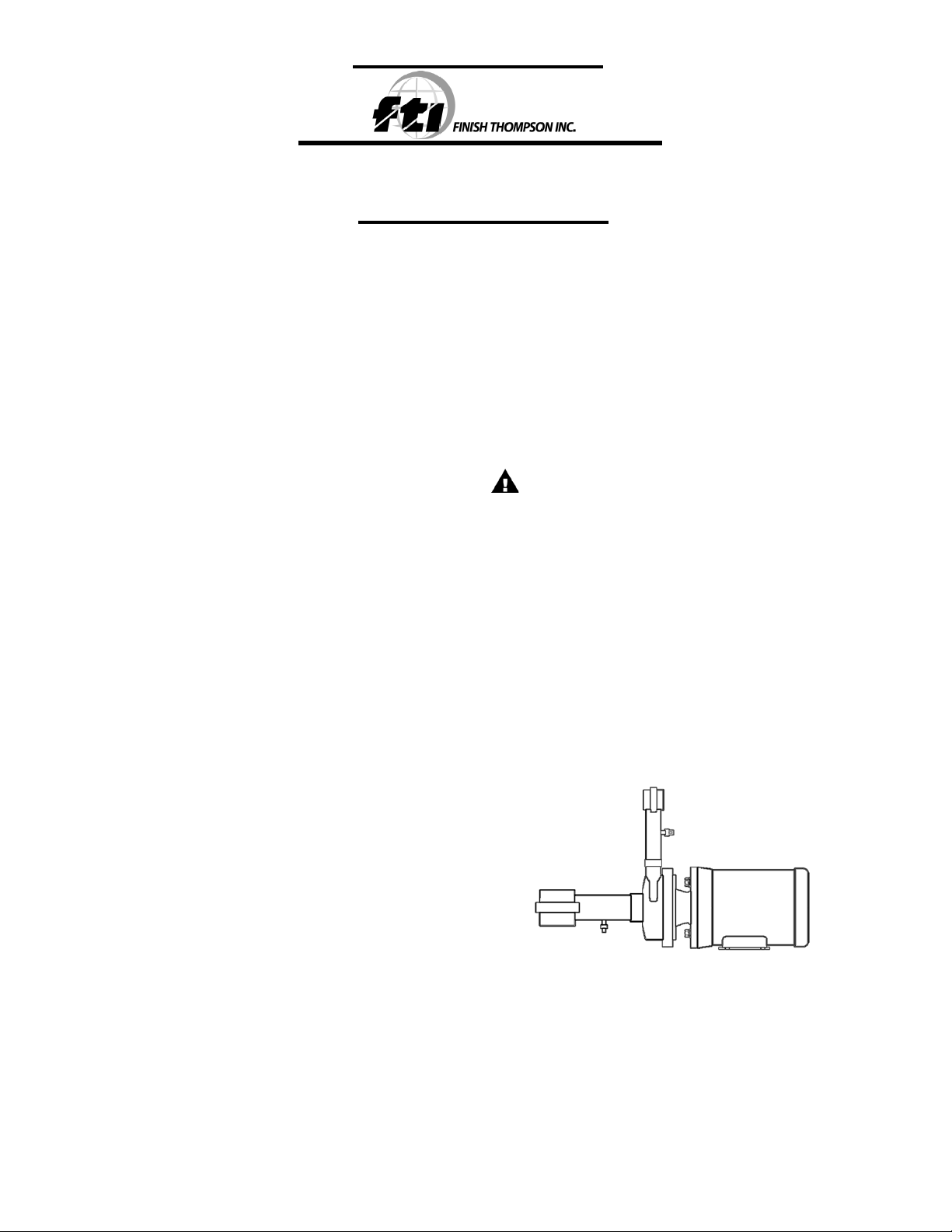
AC6 & AC8 HORIZONTAL SERIES
Sealed Metallic Centrifugal Pumps
Installation and Maintenance Instructions
ASSEMBLY
PUMPS WITH MOTORS
1. No assembly required. Unpack the pump and motor and examine for any signs of shipping damage. If damage is detected,
save the packaging and notify the carrier immediately.
2. Proceed to the “Installation” section of these instructions.
PUMPS WITHOUT MOTORS
Note: Do not remove shipping plug located in suction port of
the pump until the pump is completely assembled onto the
motor.
1. Unpack the pump and examine for any signs of shipping damage. If damage is detected, save the packaging and notify the
carrier immediately.
Special Note: AC6HJS 90 frame only -
a. Using the hardware provided (items 9, 10, & 11), bolt
the motor adapter (item 8) to the motor.
b. Attach the mounting plate (item 14) to the motor
adapter using the hardware provided (items 12 & 13).
c. Proceed to page 2 of the Installation and Maintenance
Manual and follow steps 1 through 9 under “Reassembly.”
2. Insert key into motor keyway. Visually determine key location
in pump end. Align keyway slots on motor shaft and pump
impeller sleeve. Slide pump assembly over the motor shaft
until the pump motor adapter (item 8) is completely seated
over the motor rabbet. The drain slot should always be on
the bottom. Install 4 bolts with flat washers and lock washers
(items 9,10,11) into the motor face. Securely tighten bolts.
3. Lubricate o-ring of self-sealing bolt (item 6) with suitable,
compatible lubricant. Insert self-sealing bolt through shipping
plug and into the eye of the impeller using a 9/16” deep well
socket. Insert a screwdriver into the motor fan to prevent
motor shaft from rotating. Tighten the bolt to 12-ft lbs.
4. Remove the shipping plug from the suction port.
5. Rotate the motor fan by hand and check for impeller rubbing.
If the impeller rubs, verify that the self-sealing bolt is properly
installed.
6. Proceed to the “Installation” section of these instructions.
INSTALLATION
MOUNTING
Motor or base plate must be securely fastened.
PIPING TO AND FROM THE PUMP:
• Always support the piping near the pump to minimize
stress and strain on the pump’s casing.
• Minimize frictional losses by increasing the suction piping size
by one diameter.
• Use a minimal number of bends on suction piping, keeping
any bends a minimum of ten pipe diameters from the pump.
• Install a shut off valve on the suction line and a flow control
valve in the discharge line. Place the valves a minimum of ten
• pipe diameters from the pump.
• Ensure that the piping is leak free.
• Position the pump as close to the liquid source as possible.
• Maintain a flooded suction at all times or prime the pump and
maintain prime at all times.
CAUTION: Do not run the pump dry. This pump should
never be started without liquid in the casing.
The fluid being transferred by the pump lubricates the pump
components. Even short periods of running the pump dry
could damage the pump. It is recommended that run dry
protection be used.
Optional electronic power monitors are available to help protect against run dry.
PUMPING LIQUIDS THAT MAY SOLIDIFY OR CRYSTALLIZE
Add a flush system to the pump’s piping to prevent accumulation
of material inside the pump. Install water inlet and outlet valves
as shown in Figure 1. Refer to the “Operation” section of these
instructions for the flush procedure.
Figure 1
ELECTRICAL CONNECTIONS
1. Perform the motor wiring according to NEC requirements and
local electrical codes.
2. Wire the motor for clockwise rotation when facing the fan end
of the motor.
3. To verify correct motor rotation
a. Install the pump into your system.
b. Fully open the suction and the discharge valves.
c. Allow fluid to flow into the pump. Do not allow the pump to
run dry, as this will cause damage to the seal components.
Page 2
d. Jog the motor (allow it to run for only one to two seconds)
and observe the rotation of the motor fan. Refer to the
directional arrow on the pump if needed.
Note: A pump running backwards will pump but at a greatly
reduced flow and pressure.
OPERATION
FLOODED SUCTION SYSTEMS:
1. Fully open the suction and discharge valves.
2. Start the pump and verify liquid is flowing. If there is no liquid flow,
refer to the “Troubleshooting” section of these instructions.
3. Adjust the flow rate and pressure by regulating the discharge
valve.
CAUTION: Never use the suction valve to adjust the liquid
flow. Limiting the suction will result in damage to pump
components.
FLUSHING SYSTEMS EQUIPPED WITH FLUSH VALVES
1. Fully close the suction and discharge valves.
2. Connect the water supply to the water inlet valve and connect
a drain hose to water outlet valve.
3. Turn on the water supply and open the inlet and outlet valves.
Flush the system until the pump has been cleared of any material
buildup (usually approximately 5 minutes).
4. Close the water inlet and outlet valves and turn off water supply.
MAINTENANCE
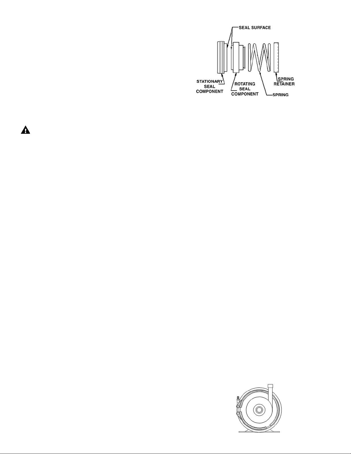
SEAL REPLACEMENT DISASSEMBLY
1. Disconnect power. Remove electrical wiring.
2. Close the suction and the discharge valves. Disconnect the
piping. Remove any mounting bolts.
3. For AC6 pumps - To remove the v-clamp (item 2) and the impeller housing (item 1), first apply a thread lubricant to the threaded
rod portion of the v-clamp, then remove the nut. Remove the
v-clamp, the housing, and the o-ring (item 3).
For AC8 pumps - Remove the 8 housing bolts and all the
hardware (items 15,16,17, 18). Remove the impeller housing
(item 1) and the o-ring (item 3).
4. Place a screwdriver in the motor fan to prevent rotation and
remove the self-sealing bolt (item 6).
Note: Do not reuse the self-sealing bolt.
5. Remove impeller (item 4), rotating seal component, seal spring
and seal spring retainer. Discard seal components after removal.
(See Figure 2).
6. Remove backhead assembly (item 7) and press out the stationary seal component. Discard stationary seal component after
removal.
Figure 2
Note: Keep the polished surface of the seal face clean. Use a
piece of cardboard to protect the seal while pressing against
the stationary face.
2. Press the stationary seal into the seal seat of the backhead
assembly so that the seal surface points away from the motor
face. Place backhead into motor adapter.
3. Place the spring retainer and seal spring onto the impeller
sleeve.
4. Lubricate the inside diameter of the rotating seal component
with P-80 (or equivalent) or soapy water and press it over the
impeller sleeve (item 4) with the rotating face pointed away
from the impeller as shown in Figure 2 (towards the stationary
face).
5. Insert key into the motor keyway. Visually determine key location in impeller sleeve. Align keyway slots on motor shaft and
impeller sleeve. Slide impeller assembly over the motor shaft.
Lubricate o-ring of new self-sealing bolt (item 6) with suitable,
compatible lubricant. Insert self-sealing bolt into the eye of the
impeller using a 9/16” deep well socket. Insert a screwdriver
into the motor fan to prevent motor shaft from rotating. Tighten
the bolt to 12-ft lbs.
6. Place impeller housing (item 1) over backhead (item 7) and
o-ring (item 3) and make sure discharge is in the correct orientation (usually 12 o’clock).
7. For AC6 pumps – Place the v-clamp (item 2) over the impeller
housing, backhead, and the mounting plate (item 14). Make
sure the discharge is level and in the correct orientation (see
Figure 3). Tighten the nut on the v-clamp. Firmly tap the vclamp with a mallet in several spots, and then retighten the
nut.
For AC8 pumps- Insert the mounting bolts with flat washer
(items 15 &16) through the impeller housing (item 1), the
backhead (item 7), and the mounting plate (item 14), and tighten
with the correct hardware (items 15,17, and 18).
8. Rotate the motor fan by hand and check for impeller rubbing.
If the impeller rubs, verify that the self-sealing bolt is properly
installed.
9. Reinstall the pump into the system.
REASSEMBLY
1. Lubricate the rubber portion of the new stationary seal (item
5) with P-80 (or equivalent) or use soapy water. Do not use
petroleum products to lubricate the rubber.
Figure 3
2
Page 3

AC 6 EXPLODED VIEW
AC 8 EXPLODED VIEW
3
Page 4

C/R/K
C/R/K
4
Page 5

5
Page 6

TROUBLESHOOTING
NO OR INSUFFICIENT FLOW:
1. Pump not primed.
2. Closed valve.
3. Viscosity too high.
4. Air leaks in suction piping.
5. Discharge head higher than anticipated.
6. Suction lift too high or insufficient NPSH.
7. Check for clogged suction line.
INSUFFICIENT PRESSURE:
1. Air or gas in liquid.
2. Impeller diameter too small.
3. Discharge head higher than anticipated.
4. Motor speed insufficient (too low) or rotation incorrect.
LOSS OF PRIME:
1. Leaking suction line.
2. Foot valve or suction opening not submerged enough.
3. Foot valve too small or leaking.
4. Air or gas in liquid.
5. Foreign matter in impeller.
EXCESSIVE POWER CONSUMPTION:
1. Head lower than rating. Excessive flow.
2. Specific gravity or viscosity of liquid is too high.
EXCESSIVE VIBRATION:
1. Loose piping or bolts.
2. Pump cavitating from improper suction or feed.
These items must be considered as a system when assessing an
ATEX application.
WARRANTY
Finish Thompson, Inc (manufacturer) warrants this pump product to be
free of defects in materials and workmanship for a period of one year
from date of purchase by original purchaser. If a warranted defect, which
is determined by manufacturer’s inspection, occurs within this period, it
will be repaired or replaced at the manufacturer’s option, provided (1) the
product is submitted with proof of purchase date and (2) transportation
charges are prepaid to the manufacturer. Liability under this warranty is
expressly limited to repairing or replacing the product or parts thereof
and is in lieu of any other warranties, either expressed or implied. This
warranty does apply only to normal wear of the product or components.
This warranty does not apply to products or parts broken due to, in whole or
in part, accident, overload, abuse, chemical attack, tampering, or alteration.
The warranty does not apply to any other equipment used or purchased in
combination with this product. The manufacturer accepts no responsibility
for product damage or personal injuries sustained when the product is
modified in any way. If this warranty does not apply, the purchaser shall
bear all cost for labor, material and transportation.
Manufacturer shall not be liable for incidental or consequential damages
including, but not limited to process down time, transportation costs,
costs associated with replacement or substitution products, labor costs,
product installation or removal costs, or loss of profit. In any and all
events, manufacturer’s liability shall not exceed the purchase price of the
product and/or accessories.
Call our toll free Technical Service Hot Line, 1-800-888-3743, if you
have any questions regarding product operation or repair.
For further information, contact Finish Thompson Inc. or your local
distributor.
SAFETY PRECAUTIONS FOR ATEX PUMPS
WARNING: Proper materials of construction must be chosen
for the fluid being pumped. Improper material selection could lead
to pump failure and leakage. This is the responsibility of the end
user.
WARNING: ATEX pumps must have a power monitor, flow switch,
pressure switch or similar device installed to protect against running
dry, closed discharge valve, major leaks, and possible sources of
ignition due to motor bearing failure. Any of these conditions could
lead to a rise in surface temperature of the pump. The device must be
set to stop the pump within three seconds of a fault.
WARNING: The pump must be checked for leaks on a regular
basis. If leaks are detected, the pump must be repaired or replaced
immediately.
WARNING: The pump must be cleaned on a regular basis to avoid
dust buildup greater than 5mm.
TEMPERATURE CLASSIFICATION
Pump temperature is completely dependent on operating conditions.
Pump will transfer heat from the piping system, motor, and fluid.
ADDITIONAL INFORMATION
ORDERING SPARE PARTS:
Spare parts can be ordered from your local distributor. Always refer to
pump model number to avoid error.
OTHER FTI PRODUCTS:
Drum Transfer Pumps are available in sanitary construction, stainless
steel, polypropylene and CPVC. Flows to 40 gpm, discharge heads to 80
feet and viscosities to 15,000 cps.
Portable Mixers for turbine mixing and blending handle viscosities to
1,000 cps with gentle, non-vortex circulation. Available in 316 stainless
steel construction.
Sealed Centrifugal Pumps in GF polypropylene and CF PVDF come with a
wide variety of sealing materials. Flows to 250 gpm, discharge heads to
130 feet and temperatures to 200oF (93ºC).
Sealless Mag Drive Centrifugal Pumps in GF polypropylene and CF PVDF.
Flows to 250 gpm and discharge heads to 135 feet. Handles temperatures
up to 220°F and have 30-minute run-dry capability. Mounts to standard
frame motors.
Part No. J103532, Rev. 9
Literature ID No.FT00-793G, 10-31-08
 Loading...