

Page 1
AC 4 & 5 HORIZONTAL SERIES
Sealed Metallic Centrifugal Pumps
Installation and Maintenance Instructions
ASSEMBLY
PUMPS WITH MOTORS
1. No assembly required. Unpack the pump and motor and examine
for any signs of shipping damage. If damage is detected, save the
packaging and notify the carrier immediately.
2. Proceed to the “Installation” section of these instructions.
PUMPS WITHOUT MOTORS
Note: Do not remove shipping plug located in suction port of the
pump until the pump is completely assembled onto the motor.
1. Unpack the pump and examine for any signs of shipping damage.
If damage is detected, save packaging and notify the carrier immediately.
2. Place the motor on the fan cover. Align any set screw (item 9) with
key slot in motor shaft. Place the aluminum motor adapter (item
8) onto the motor rabbet. Position the slot (shaft sleeve set screw
access hole) in motor adapter with the top of the motor. Line up
the bolt holes in the motor adapter with the bolt holes in the motor
face. Install (4) bolts and lock washers (items 10,11). Securely
tighten.
3. Through the top and bottom access holes, tighten securely two of
the four set screws on the shaft adapter (item 6). You will need an
1/8” Allen wrench for this.
4. Remove the screw from the shipping plug and then remove the plug
from the suction port. Rotate the motor fan until you can tighten
the two remaining set screws on the shaft adapter.
5. Rotate the motor fan by hand and check for impeller rubbing. If
the impeller rubs loosen the shaft adapter set screws and adjust
the impeller accordingly. Retighten the shaft adapter set screws.
6. Proceed to the “Installation” section of these instructions.
INSTALLATION
MOUNTING
Motor or base plate must be securely fastened.
PIPING TO AND FROM THE PUMP
• Always support the piping near the pump to minimize stress
and strain on the pump’s casing.
• Minimize frictional losses by increasing the suction piping size
by one diameter.
• Use a minimal number of bends on suction piping. Keep
bends beyond a distance of ten pipe diameters from the pump.
• Install shut off valve on the suction line and flow control valve
in the discharge line. Place the valves beyond a distance of ten
pipe diameters from the pump.
• Ensure that the piping is leak free.
• Position the pump as close to the liquid source as possible.
• Maintain a flooded suction at all times or prime the pump and
maintain prime at all times.
CAUTION: Suction prime must be maintained at all times.
Running the pump dry will cause damage to pump components.
To protect the pump if prime is lost, use a pressure switch on the
discharge, a vacuum switch on the suction, or a motor minder to
monitor motor current draw.
PUMPING LIQUIDS THAT MAY SOLIDIFY OR CRYSTALLIZE:
Add a flush system to the pump’s piping to prevent accumulation of material
inside the pump. Install water inlet and outlet valves as shown in Figure 1.
Refer to the “Operation” section of these instructions for the flush procedure.
Figure 1
ELECTRICAL CONNECTIONS
1. Perform the motor wiring according to NEC requirements and local
electrical codes.
2. Wire the motor for clockwise rotation when facing the fan end of the
motor.
3. To verify correct rotation of the motor:
a. Install the pump into the system.
b. Fully open the suction and discharge valves.
c. Allow fluid to flow into the pump. Do not allow the pump
to run dry. Running the pump dry can damage internal parts.
d. Jog the motor (allow it to run for only 1-2 seconds) and
observe the rotation of the motor fan. Refer to the directional
on the arrow pump if needed.
NOTE: A pump running backwards will pump, but at a greatly
reduced rate.
OPERATION
FLOODED SUCTION SYSTEMS
1. Fully open the suction and discharge valves.
2. Start the pump and verify liquid is flowing. If there is no liquid
flow, refer to the “Troubleshooting” section of these instructions.
3. Adjust the flow rate and pressure by regulating the discharge valve.
CAUTION: Never attempt to adjust the liquid flow with the suction
valve. Limiting suction will damage pump components.
FLUSHING SYSTEMS EQUIPPED WITH FLUSH VALVES:
1. Fully close the suction and discharge valves.
2. Connect the water supply to the water inlet valve and connect a
drain hose to water outlet valve.
3. Turn on the water supply and open the inlet and outlet valves. Flush
the system until the pump has been cleared of any material buildup
(usually approximately 5 minutes).
4. Close the water inlet and outlet valves and turn off water supply.
1
Page 2
MAINTENANCE
DISASSEMBLY
1. Disconnect power. Remove electrical wiring.
2. Close the suction and discharge valves and disconnect all piping.
3. Loosen and remove the nut on the V-clamp stud. Remove the Vclamp (item 2) and the impeller housing (item 1). Note V-clamp
stud and discharge spout location for reassemble alignment.
4. Remove the motor fan cover and fan. Secure the motor shaft to
prevent it from turning, and unthread the impeller.
NOTE: Shaft adapter threads are coated with Loctite Threadlocker
#262 to prevent the impeller from spinning off if the motor is inadvertently wired for incorrect rotation. If necessary follow Loctite’s
recommendations for loosening the threadlocker #262.
5. Remove the seal spring retainer, spring, and the rotating seal
component from the shaft adapter. Remove the backhead (item
7) from the pump. Remove the stationary part of the seal from
the backhead.
6. If the motor is being replaced, proceed to step 7. If the seal is being
replaced, do not loosen or remove the shaft adapter (item 6) from
the motor shaft. Proceed to step 3 of the reassembly instructions
7. Remove the four bolts holding the motor adapter/mounting plate
assembly (items 8 & 15) to the motor and remove the motor
adapter. Loosen all four setscrews and remove the shaft adapter.
8. Inspect all parts for wear and replace as required. Note the finish on the shaft adapter where the rotating seal boot is located. If
damaged or not smooth, replace the shaft adapter.
REASSEMBLY
1. Install the shaft adapter (item 6) onto the motor shaft. Be sure one
of the setscrews is protruding into the motor shaft keyway slot, but
do not tighten any setscrews yet.
2. Install the motor adapter/mounting plate assembly (8 & 15) with
setscrews access slots at 12 and 6 location, and tighten all four
bolts.
3. Lubricate the outer boot on the stationary part of the seal with a
chemically compatible lubricant, and press into the backhead (item
7) until it is fully seated. The polished seal surface should be facing
away from the motor.
NOTE: To keep the polished surface of the seal face clean, use a
piece of cardboard to protect the seal face during installation.
4. Insert the backhead (item 7) into the motor adapter (item 8) bore
and press into place.
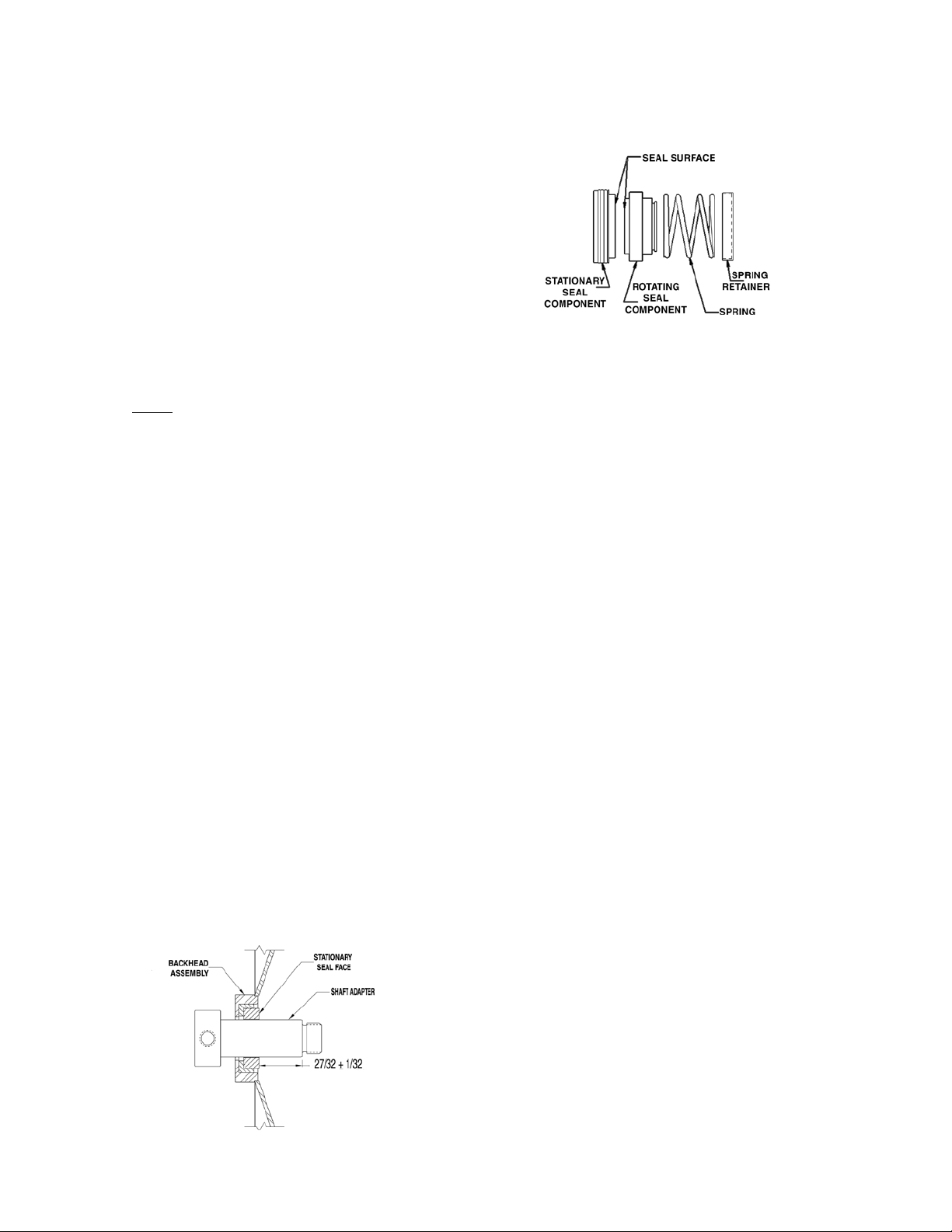
If the shaft adapter was not loosened or removed, go to step 5. If
replacing the shaft adapter, firmly hold the backhead toward the
motor, and adjust the shaft adapter until the shoulder is .843 (27/32)
inches from the stationary seal face (see figure 2). Tighten all four
setscrews with a T wrench through the access slots in the motor
adapter.
Figure 2
5. Lubricate the inside of the rotating seal component with a chemically
compatible lubricant and carefully slide it over the shaft adapter
with a rotating face pointing at the motor (as shown in figure 3).
NOTE: Rotating seal must be completely seated against the station-
ary seal face.
Figure 3
6. Place the seal spring and spring retainer over the shaft adapter.
NOTE: To prevent spinning the impeller off in case the motor is
wired for incorrect rotation, it is recommended to coat the shaft
adapter threads with Loctite Threadlocker #262.
7. Holding the motor shaft firmly, thread the impeller onto the shaft
adapter until it stops at the adapter shoulder.
8. Lubricate the housing o-ring (item 3) with chemically compatible
lubricant, and install onto the backhead. Install the impeller housing (item 1), the V-clamp (item 2), and the nut onto the V-clamp
stud. Verify the V-clamp stud and housing discharge orientation
and tighten the V-clamp. Firmly tap the V-clamp to seat it in several
places and retighten the V-clamp nut.
9. Rotate the motor shaft by hand to verify there is no rubbing. Replace
the motor fan and fan cover. Reinstall the pump into the system.
TROUBLESHOOTING
NO OR INSUFFICIENT FLOW
1. Pump not primed.
2. Closed valve.
3. Viscosity too high.
4. Air leaks in suction piping.
5. Discharge head higher than anticipated.
6. Suction lift too high or insufficient NPSH.
7. Check for clogged suction line.
8. Motor wired for wrong rotation.
INSUFFICIENT PRESSURE
1. Air or gas in liquid.
2. Impeller diameter too small.
3. Discharge head higher than anticipated.
4. Motor speed insufficient (too low) or motor rotation incorrect.
LOSS OF PRIME
1. Leaking suction line.
2. Foot valve or suction opening not submerged enough.
3. Foot valve too small or leaking.
4. Air or gas in liquid.
5. Foreign matter in impeller.
EXCESSIVE POWER CONSUMPTION
1. Head lower than rating. Excessive flow.
2. Specific gravity or viscosity of liquid is too high.
EXCESSIVE VIBRATION
1. Loose piping or bolts.
2. Pump cavitating from improper suction or feed.
2
Page 3

AC4 EXPLODED VIEW
11
8
10
15
2
9
6
3
7
5
4
1
12
14
13
AC5 EXPLODED VIEW
17
8
16
12
11
Item Qty Description
Impeller Housing
AC4 3/4” x 1/2” A102106-1*
1 1
2 1
3 1
4 1
**To order a housing with BSP threads, substitute the number following the dash with the number in parentheses.
*Universal FNPT & BSP
AC5 1 1/4” x 3/4” A102113-1(2) A102112-2(4)
AC5 1 1/2” x 1 1/4 A102112-1(3) A102133-3(4)
AC5 2” x 1 1/2” A102133-1(2)
AC5H 1/2” x 1/4” (high head) A102120-1(2)
V-Clamp
O-Ring
FKM J 102946 J102960 J102960
EPDM J103004 J103003 J103003
Buna (FDA compliant) 108213 108214 108214
PTFE J103042 J103043 J103043
Impeller
AC4/AC5R 3” A102105-1 A102105-1
AC4 3 1/4” A102105-2 A102105-2
AC4/AC5R 3 1/2” A102105-3 A102105-3
AC5R 3 3/4” A102105-4
AC5R 4 1/2” A102105-5
AC5 4” x 3/8” vane A102114-9
AC5 4 1/4” x 3/8” vane A102114-10
AC5 4 1/2” x 3/8” vane A102114-11
AC5 4 3/4” x 3/8” vane A102114-12
AC5 4” x 1/4” vane A102114-1
AC5 4 1/4” x 1/4” vane A102114-2
AC5 4 1/2” x 1/4” vane A102114-3
AC5 4 3/4” x 1/4” vane A102114-4
AC5H 4 3/4” x 1/8” vane (high head) A102183
AC4 Part
J102947 J102947 J102947
14
Number
15
9
6
13
10
FNPT (BSP)**
3
4
5
7
AC5 Part Number
AC5S
1
2
AC5R
FNPT (BSP)**
3
Page 4

Item Qty Description
Seal
3/4” Carbon/Ceramic/FKM Seal J102957-1 J102957-1 J102957-1
3/4” Carbon/Ceramic/EPDM Seal J102957-2 J102957-2 J102957-2
5 1
6 1
7 1
8 1
9 4
10 4
11 4
12 1
13 4
14 4
15 1
16 1
17 4
3/4” Carbon/Ceramic/Buna Seal (FDA compliant) 108073 108073 108073
3/4” Carbon/Ceramic/Kalrez Seal J103081 J103081 J103081
3/4” Silcarb./Silcarb./FKM Seal J103066 J103066 J103066
3/4” Silcarb./Silcarb./EPDM Seal J103067 J103067 J103067
Shaft Adapter w/ Set Screws
56C Frame A102895 A102895 A102895
71-B14 Frame A102896 A102896 A102896
80 Frame A102897 A102897
90 Frame A102898 A102898
Backhead
Motor Adapter
56C Frame M102049-1 M102049-1 M102049-1
71-B14 Frame M102049-2 M102049-2 M102049-2
80 Frame M102049-3 M102049-3
90 Frame M102049-4 M102049-4
1/4-20 x 1/4” Cup Point Set Screw
Hex Head Cap Screw
3/8-16 x 1” (56C Frame) J100114 J100114 J100114
M6 x 25 mm (71-B14 & 80 Frame) J103456 J103456 J103456
M8 x 40 mm (90 Frame) J102760 J102760
Lock Washer
3/8” (56C) J100115 J100115 J100115
5/16” (90 Frame only) J101282 J101282
1/4” (71-B14 & 80 Frame) J100672 J100672 J100672
Slinger Ring
56C Frame M102064-1 M102064-1 M102064-1
71-B14 Frame M102064-2 M102064-2 M102064-2
80 Frame M102064-3 M102064-3
90 Frame M102064-4 M102064-4
Cap Screw Fillister Head (all)
#10 Lock Washer (all)
Mounting Plate
Metric Motor Adapter (90 Frame only)
Flat Washer - 5/16” (90 Frame only)
AC4 Part
Number
A102110-1 A102121-1 A102121-1
J100220 J100220 J100220
J100932 J100932 J100932
J100824 J100824 J100824
J103389-1 J103389-1 J103389-1
AC5S Part
Number
AC5R Part
Number
M102129
J101293
SAFETY PRECAUTIONS FOR ATEX PUMPS
WARNING: Proper materials of construction must be chosen for the fluid being pumped. Improper material selection could lead to pump
failure and leakage. This is the responsibility of the end user.
WARNING: ATEX pumps must have a power monitor, flow switch, pressure switch or similar device installed to protect against running
dry, closed discharge valve, major leaks, and possible sources of ignition due to motor bearing failure. Any of these conditions could lead
to a rise in surface temperature of the pump. The device must be set to stop the pump within three seconds of a fault.
WARNING: The pump must be checked for leaks on a regular basis. If leaks are detected, the pump must be repaired or
replaced immediately.
WARNING: The pump must be cleaned on a regular basis to avoid dust buildup greater than 5mm.
TEMPERATURE CLASSIFICATION
Pump temperature is completely dependent on operating conditions. Pump will transfer heat from the piping system, motor, and fluid.
These items must be considered as a system when assessing an ATEX application.
4
Page 5

WARRANTY
Finish Thompson, Inc (manufacturer) warrants this pump product
to be free of defects in materials and workmanship for a period of
one year from date of purchase by original purchaser. If a warranted defect, which is determined by manufacturer’s inspection,
occurs within this period, it will be repaired or replaced at the
manufacturer’s option, provided (1) the product is submitted with
proof of purchase date and (2) transportation charges are prepaid
to the manufacturer. Liability under this warranty is expressly
limited to repairing or replacing the product of parts thereof and
is in lieu of any other warranties, either expressed or implied.
This warranty does apply only to normal wear of the product or
components. This warranty does not apply to products or parts
broken due to, in whole or in part, accident, overload, abuse,
chemical attack, tampering, or alteration. The warranty does not
apply to any other equipment used or purchased in combination
with this product.
The manufacturer accepts no responsibility for product damage
or personal injuries sustained when the product is modified in
any way. If this warranty does not apply, the purchaser shall bear
all cost for labor, material and transportation.
Manufacturer shall not be liable for incidental or consequential
damages including, but not limited to process down time, transportation costs, costs associated with replacement or substitution
products, labor costs, product installation or removal costs, or
loss of profit. In any and all events, manufacturer’s liability shall
not exceed the purchase price of the product and/or accessories.
CHEMICAL REACTION DISCLAIMER
The user must exercise primary responsibility in selecting the
product’s materials of construction, which are compatible with the
fluid(s) that come(s) in contact with the product. The user may
consult Finish Thompson, Inc. (manufacturer) and a manufacturer’s
representative/distributor agent to seek a recommendation of the
product’s material of construction that offers the optimum available
chemical compatibility.
However neither manufacturer nor agent shall be liable for product
damage or failure, injuries, or any other damage or loss arising out
of a reaction, interaction or any chemical effect that occurs between
the materials of the product’s construction and fluids that come into
contact with the product’s internals.
Call our toll free Technical Service Hot Line, 1-800-888-3743, if you
have any questions regarding product operation or repair.
Tech Service: 800-888-3743
P/N J103334, Rev. 17, 3/5/13
Lit. I.D. No. FT98-718O
5
 Loading...