

Page 1
GENERAL INFORMATION
TABLE OF CONTENTS
Safety indications .............................................................................. 2
Installation ......................................................................................... 4
Specifications .................................................................................... 5
Settings and controls ........................................................................ 6
Control functions ............................................................................... 8
Operation .......................................................................................... 9
Start-up ......................................................................................... 9
Maintenance ................................................................................... 10
Trouble-shooting ............................................................................. 13
Wiring diagram ................................................................................ 14
OUTFIT
Check outfit carefully. Later claims for missing parts will not be accepted.
The following accessories are supplied with the compressor:
no. 1 line cock
no. 1 Teflon tape
no. 1 delivery tube
no. 4 anti-vibration elements
no. 1 door key
no. 1 users guide
GB
CONDITION OF THE MACHINE WHEN SUPPLIED
Every compressor is shop tested and delivered ready to be installed and to be set at work.
The oil used is SHELL CORENA D.
WARRANTY
The Manufacturer guarantees their products for manufacturing or material defects for 12 months from their delivery
date.
NOTE: Warranty terms are extended as follows only to piston pumping units:
- 18 months for models belonging to PROFESSIONAL line,
- 24 months for models belonging to HEAVY DUTY line,
- Machines belonging to ROTAR line are guaranteed for 3,000 operating hours (as shown by the hour counter)
but limited to 12 months maximum from their delivery date. The above warranty period is extended to 24 months with
no hour limit to the screw pumping unit and the electronic controller.
d) Electric part and parts subject to wear are not covered by this warranty.
e) Any repairs and/or servicing under warranty can be carried out only by Authorized Service Centers and the
Manufacturers.
f) Products can be delivered to the Manufacturer for servicing purposes only after prior authorization by the very
Manufacturer. The Manufacturer shall decide at their discretion whether authorization can be granted or require an
Authorized Service Center to take on servicing.
In any case, products shall be delivered free of any charge and will be returned to the Customer on ex-factory basis.
g) This warranty covers free-of-charge repairs or replacement of those machine parts, which have been acknowledged
as faulty by our authorized technicians.
h) This Warranty becomes null and void in case of accidental damages due to negligence, incorrect or improper
use and installation or in case of use and installation, which do not comply with the instructions given in the Instruction
Manual as well as in case of changes or repairs carried out by non-authorized personnel. All defective parts, which are
replaced under warranty, are collected by the Authorized Service Center.
i) This warranty does not cover any repairs or compensation for transport damages (to or from the Authorized
Service Center).
k) Any compensations for damages caused to objects or injuries caused to people due to improper use of the
purchased compressor are excluded from this warranty.
l) Machines under warranty can be serviced against purchase documents bearing the purchasing date only if the
Purchaser has met all contract and payment requirements.
m) This Warranty is the only one which is acknowledged by the Manufacturer. The issue of any other verbal or
written warranty is not allowed. Also, no changes to the terms of this Warranty are allowed,
Any dispute shall be settled by the Court of Bologna.
Rotar Plus 20-25 Easytronic - Cod.197AA2702 - Edition 00 01/2004
1
Page 2
GB
SAFETY INDICATIONS
GENERAL
Rotary compressors are intended for heavy continuous industrial use. They are especially suitable for industrial applications
requiring high air consumption for a long time.
The compressor should be run and operated only in compliance with the indications given in this manual. Safely keep this
manual in a known and easily reachable place for the whole working life of the compressor.
A supervisor shall be appointed in the company, in which the compressor is installed. He/she shall be responsible for
compressor inspections, adjustments and maintenance. Should a substitute be appointed for the supervisor, he/she shall carefully
read the users guide and all possible comment on service and maintenance carried out so far.
SYMBOLS USED IN THE MANUAL
Some symbols are used to highlight danger situations, give recommendations or information. These symbols are usually
positioned next to the text, a figure or at the top of a page (in this case they refer to all subjects dealt with in that page).
Carefully read symbol meaning below.
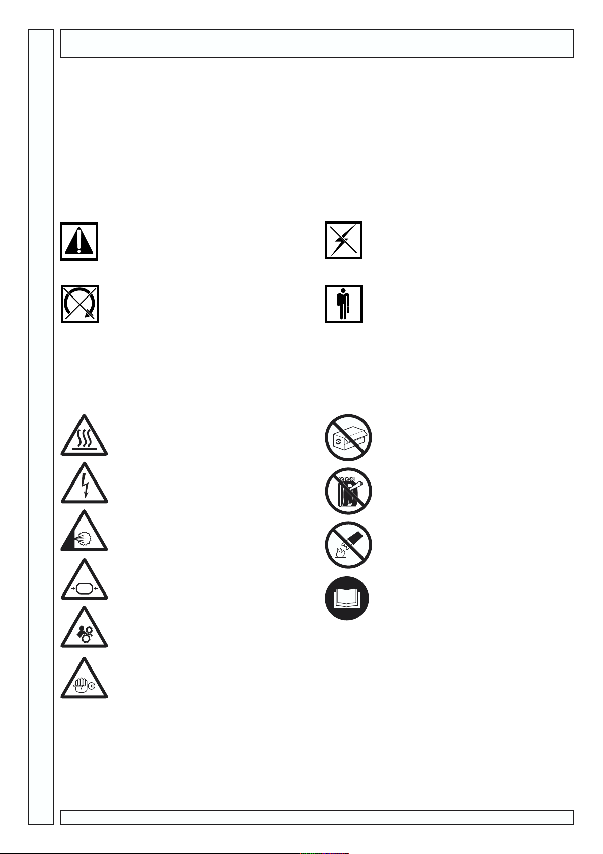
CAUTION!
Important description on service, dangerous
situation, safety, accident prevention
recommendations and/or very important information.
STOP MACHINE!
All operations to be strictly carried out only after
stopping the machine.
POWER OFF!
All operations to be strictly carried out only after
powering off the machine.
SPECIALIZED PERSONNEL!
All operations to be strictly carried out only by
specialized technician.
SYMBOLS ON THE COMPRESSOR
The compressor has several labels to highlight possible danger and give recommendations on what to do during machine
operation or in special situations.
Please comply with these indications.
Danger! Hot!
Danger! Electric shock!
Prohibited! Do not open doors during
compressor operation
Prohibited! Press emergency button for
compressor immediate stop. Do not use line knife
switch.
2
Danger! Hot gas or harmful gas within working
area
Danger! Pressurized container
Danger! Mechanical moving parts
Caution! Maintenance works in progress
Rotar Plus 20-25 Easytronic - Cod.197AA2702 - Edition 00 01/2004
Prohibited! Do not use water on electric
equipment to extinguish fire.
Compulsory! Read instructions for use
carefully.
Page 3
SAFETY INDICATIONS
WHAT TO DO:
Make sure that mains voltage corresponds to the voltage indicated on CE plate and that cable of suitable cross-section are
used for electric connections.
Always check oil level before starting the compressor.
Be familiar with emergency stop control and all other controls.
Empty the air tank and/or oil separator and unplug the connector before any maintenance work, so to avoid accidental start.
Ensure that all parts have been correctly reassembled after any maintenance work.
Keep children and animals off the working area to avoid injuries caused by devices connected to the compressor.
Carefully read instructions for the installed accessory, especially if painting devices are installed.
Ensure that the installation place is properly ventilated.
Ensure that temperature of the working environment ranges between +5 and + 45 ºC.
The compressor should be installed and operated in a non-explosive environment.
Allow at least 50 cm between the compressor and the wall so to allow free air flow to the fan.
Press the emergency button on the control panel only in case of actual need so as to avoid possible damages to people or the
very compressor.
When calling for technical assistance and/or advice, always mention model and serial number indicated on CE plate.
Always follow the maintenance schedule specified in the users guide.
WHAT NOT TO DO:
Do not touch inner parts and pipes as they are very hot during compressor operation and stay hot for a certain time after
compressor stop.
Do not position inflammable or nylon objects or cloths close to and onto the compressor.
Do not move the compressor when the tank is under pressure.
Do not operate the compressor if the power cable is damaged or defective or if connection is unstable.
Do not operate the compressor in explosive environment or in case of naked flames.
Do not operate the compressor in wet or dusty environments.
Never aim the air jet at people or animals.
Do not allow unauthorized people to operate the compressor and give them all required instructions.
Do not hit fans with blunt objects as they might break during compressor operation.
Never operate the compressor without air filter.
Do not tamper with safety and adjusting devices.
Never operate the compressor when doors/panels are open or removed.
GB
PRODUCT IDENTIFICATION
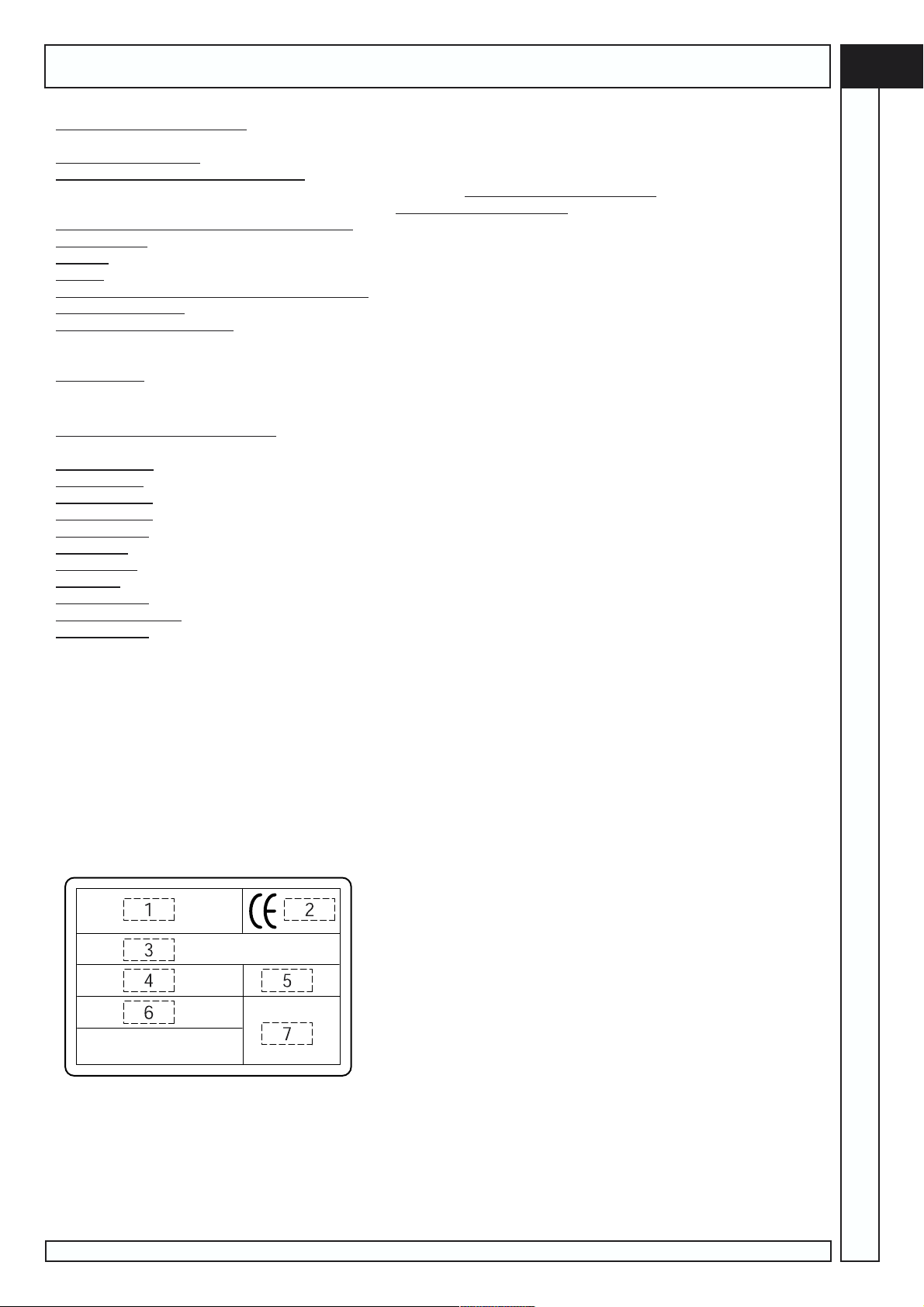
The compressor Your have purchased has its own CE plate showing the following data:
1) Manufacturers data
2) CE mark year of manufacture
3) TYPE = name of the compressor
CODE = compressor code
SERIAL NO. = serial number of the compressor You have purchased (to be always mentioned when calling for technical
assistance)
4) air delivered by the compressor expressed in (l/min) and (cfm)
5) max. operating pressure (bar and PSI) compressor noise level in dB(A)
6) electric data: voltage (V/ph), frequency (Hz), absorption (A) - power (HP and kW), rotations per minute (Rpm).
7) other approvals
Rotar Plus 20-25 Easytronic - Cod.197AA2702 - Edition 00 01/2004
3
Page 4
GB
350 cm (min)
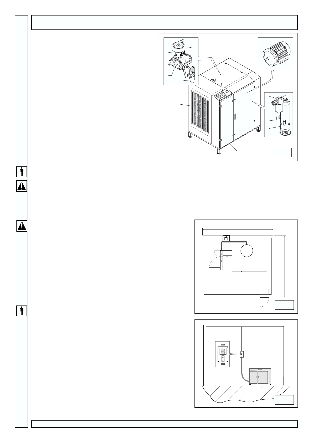
COMPRESSOR DESCRIPTION (fig.1)
Compressor main components are:
1) Air-oil radiator
2) Electric equipment
3) Instrument board
4) Oil separator tank
5) Oil separator filter
6) Minimum pressure valve
7) Electric motor
8) Screw compressor
9) Suction regulator
10) Air filter
11) Oil filter
INSTALLATION
9
8
11
1
10
7
3
6
5
4
2
UNPACKING AND HANDLING
The compressor is usually shipped to the customer with a carton cover. Wear protective gloves and cut outer straps. Remove
then package by lifting it from the top. Before removing the compressor, make sure it is intact (outside), open access doors (if
fitted) and visually check components for damage. Check that all accessories are included.
Lift machine with a transpallet or fork lift truck and transport the machine with the utmost care to the place of installation.
You are advised to keep the packing material for the event you need to re-locate the compressor. Keep package at least for the
duration of the warranty period, so the compressor can be safely shipped to a service centre, if needed.
When no longer needed, deliver packing material to the special collection centres for disposal.
PLACEMENT AND INSTALLATION (fig.2)
Upon installation, make sure that the chosen place is in compliance with all
prevailing national safety standards and meets the following requirements:
low percentage of dust suspended in air,
shop must be suitably sized and well ventilated so that room temperature never exceeds 40°C when the compressor is working. If this is not
the case, install one or more exhaust fans to extract hot air. Ideally, the fans
should be installed close to the ceiling.
Exhaust fan 2000 m3 /h code 020041000
Exhaust fan 4000 m3 /h code 020042000
Dimensions are just approximate. Try nevertheless to respect them as much
as possible.
A drainage pit or at least a canister shall be used to collect tank condensate
(see chapt. Maintenance).
80 cm (min)
90 cm (min)
POWER CONNECTION (fig.3)
Proceed to power connection with cross-section cables suitable for
machine power: 3 phase cables and 1 ground cable.
Have a switch (A) provided with plug fuses installed between supply
line and control panel, close to machine cable connections.
Switch (A) should be installed within the operators reach.
Cables shall be homologated and with a min. protection degree equal to
IP44.
NOTE: To choose cables cross-section, refer to Table page 5.
0
I
A
1
300 cm (min)
2
4
3
Rotar Plus 20-25 Easytronic - Cod.197AA2702 - Edition 00 01/2004
Page 5
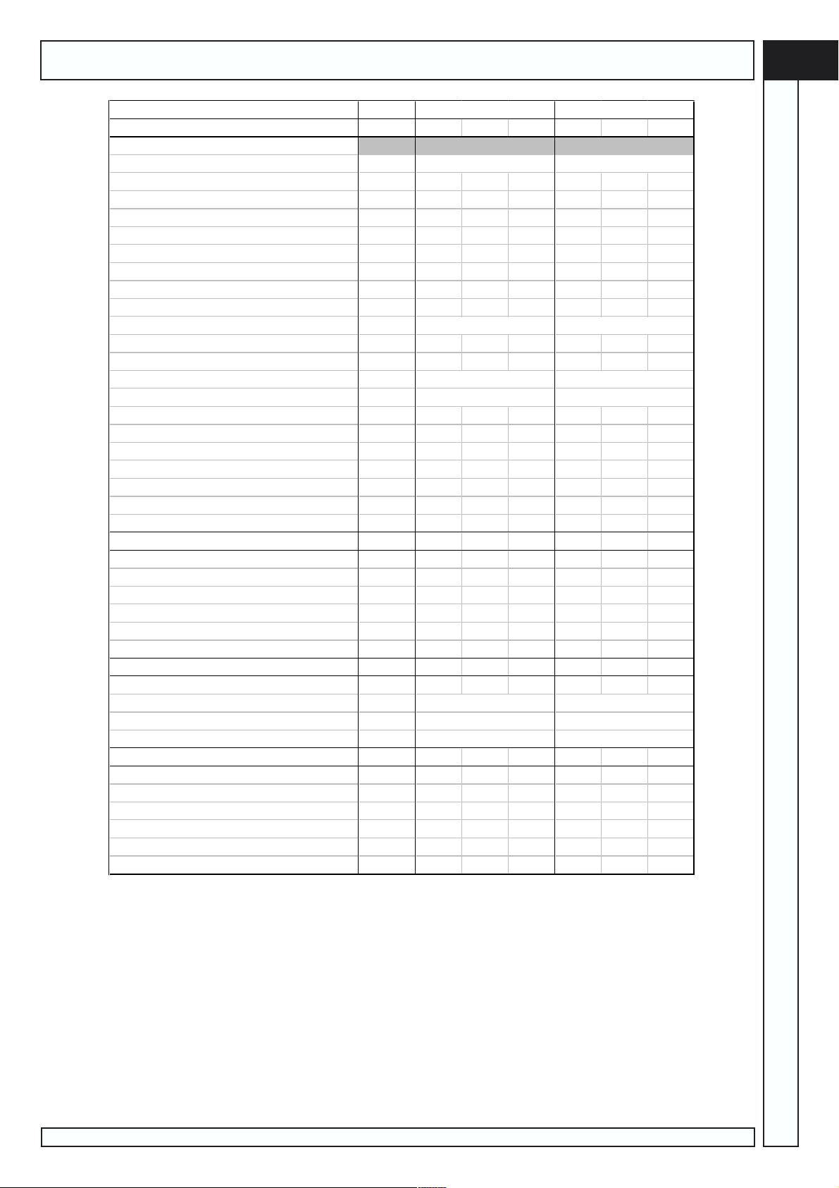
SPECIFICATIONS
7HFKQLFDOIHDWXUHV
Pressure
Compressor type
Compressor rotation speed RPM
Air volume supplied l/min
Oil quan t it y l
Oil quantity for t o pping-up l
Max. final over temperat ure °C
Remove d heat kJ / h
Fan flow rate m³ / h
Oil r esidues in the air mg / m³
Electric motor (bipolar)
Motor power kW
M ax. power absorbed kW
Voltage V/Hz
Auxiliary voltage V/Hz
Electrical box protection class IP
Motor insulation c lass
Full l oad c urrent A
Star t ing load A
Max. Start-up per hour n°
Ambient limit temperatu r e °C
Noise lev el at 1 m (Cagi pneu r op) dB ( A)
EDU
+3 +3
FS 50 TM FS 50 TM
4830 4330 3460 5640 5200 4120
2350 2050 1750 2700 2450 2050
777777
0,5 0,5 0,5 0,5 0,5 0,5
5561087
51300 51300 51300 63270 63270 63270
3100 3100 3100 2931 2931 2931
444444
132 MD/2 B3 B5
15 15 15 18,5 18,5 18,5
18,4 18,4 18,4 21,5 21,5 21,5
400 / 50 400/50
230-24 / 50-60 230-24/50-60
54 54 54 54 54 54
FFFFFF
31 31 31 36 36 36
70 75 73 98 104 107
10 10 10 10 10 10
50 50 50 50 50 50
70 70 70 71 71 70
160 L/2 B3 B5
GB
3URWHFWLRQGHYLFHV
M ax compressor temperature °C
Min. oil t emperature °C
Thermal mot or cut- out A
Safety v alve setting bar
St a r t-up pressure switc h set ting bar
'LPH QVLRQVDQGZHLJKW
Dimensions mm
Weight Kg
A ir cock f it t ing Rp
3RZHUFRQQHFWLRQ
Power kW
Cable section (max . lenght 3 mt. ) mm²
A bsorbed current A
Relay sett ing A
Switch A
110 110 110 110 110 110
-7 -7 -7 -7 -7 -7
19,8 19,8 19,8 23 23 23
14 14 14 14 14 14
1,5 1,5 1,5 1,5 1,5 1,5
1030×680×1030 1030×680×1030
300 360
3/4" 3/4"
15 15 15 18,5 18,5 18,5
666666
31 31 31 36 36 36
19,8 19,8 19,8 23 23 23
50 50 50 63 63 63
Rotar Plus 20-25 Easytronic - Cod.197AA2702 - Edition 00 01/2004
5
Page 6
GB
SETTINGS AND CONTROLS
123
45 6 7 8 9
4
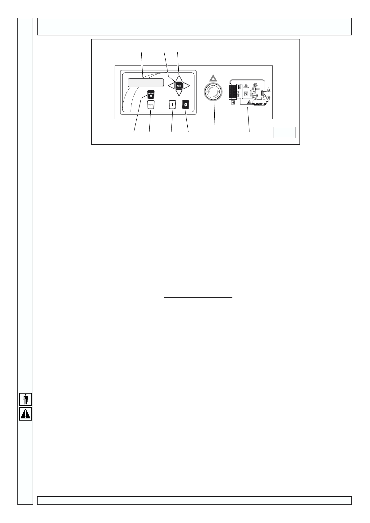
CONTROL PANEL (FIG. 4)
All compressor power-on-and-off procedures are controlled by the machine power unit. Furthermore, it signals possible
machine problems and gives information on the operation times and servicing times.
1) Display on which information is displayed.
2) OK key: press confirm (see Modifiable Parameters)
3) Direction keys: to scroll the options of the menu
4) Alarm light: if the light turns on and compressor possibly stops, it means that maintenance service is needed or a failure in
the system has occurred. Refer to Alarm messages to identify proper service.
5) Reset key: to stop the alarm (see Alarm Messages)
6) ON/I key: to power the machine on.
The machine power-on cycle is divided into three phases.
wait for power-on the (STAND_BY) message is displayed. If compressor was switched off, 15 seconds are required before
the cycle is started; otherwise compressor remains on stand-by until pressure transducer requires air.
Starting: compressor power-on in the star mode: the (LOADLESS)message is displayed
Working cycle: shift from star mode to delta mode after five seconds.
After two seconds, if required by transducer, the load solenoid valve is excited and (LOAD) message is displayed.
Note: This cycle is for compressors with a remote starter. Direct start compressors start immediately after (STAND-BY) phase.
7) OFF/0 key: to power the machine off.
Load solenoid valve is disabled, loadless cycle starts, blinking (LOADLESS) message is displayed, once loadless cycle is over
compressor stops and off message is displayed.
8) Emergency stop switch: to stop compressor
9) Functioning diagram/ maintenance operations
only in case of actual need.
WORKING TIMES
Automatic mode
The compressor operation is controlled by the pressure transducer, which stops the machine when the max. pressure
value is reached and starts it again after the pressure has decreased to the min. set value.
However, the machine stop is of the delayed type, that is it does not occur exactly at the same time when the max. pressure
value is reached but after a certain time, during which no air is taken (see no. 7 of above paragraph).
Standard setting is 20 seconds, but it is recommended to check that number of start-ups per hour does NOT exceed max
number of 10. Should it be a higher value, it is recommended to set longer loadless operation time (see no. 7, Modifiable
parameters).
PRESSURE REGULATOR
The User should install a pressure regulator downstream of the compressor to set the power line according to his/her needs.
REMOTE ON/OFF
The compressor can also be switched on or off using the remote control optional software (remote control will be active
only if the control unit at the machine is set to ON).
This function can also be managed through the remote terminal on the terminal box. In such case, manual controls will
be excluded. If the compressor starts up unexpectedly, persons happening to be nearby could be harmed or injured. With this
in mind, THIS USE IS GENERALLY NOT RECOMMENDED. The manufacturer will not be liable for any damages.
Any change must be carried out by a qualified technician.
6
Rotar Plus 20-25 Easytronic - Cod.197AA2702 - Edition 00 01/2004
Page 7
SETTINGS AND CONTROLS
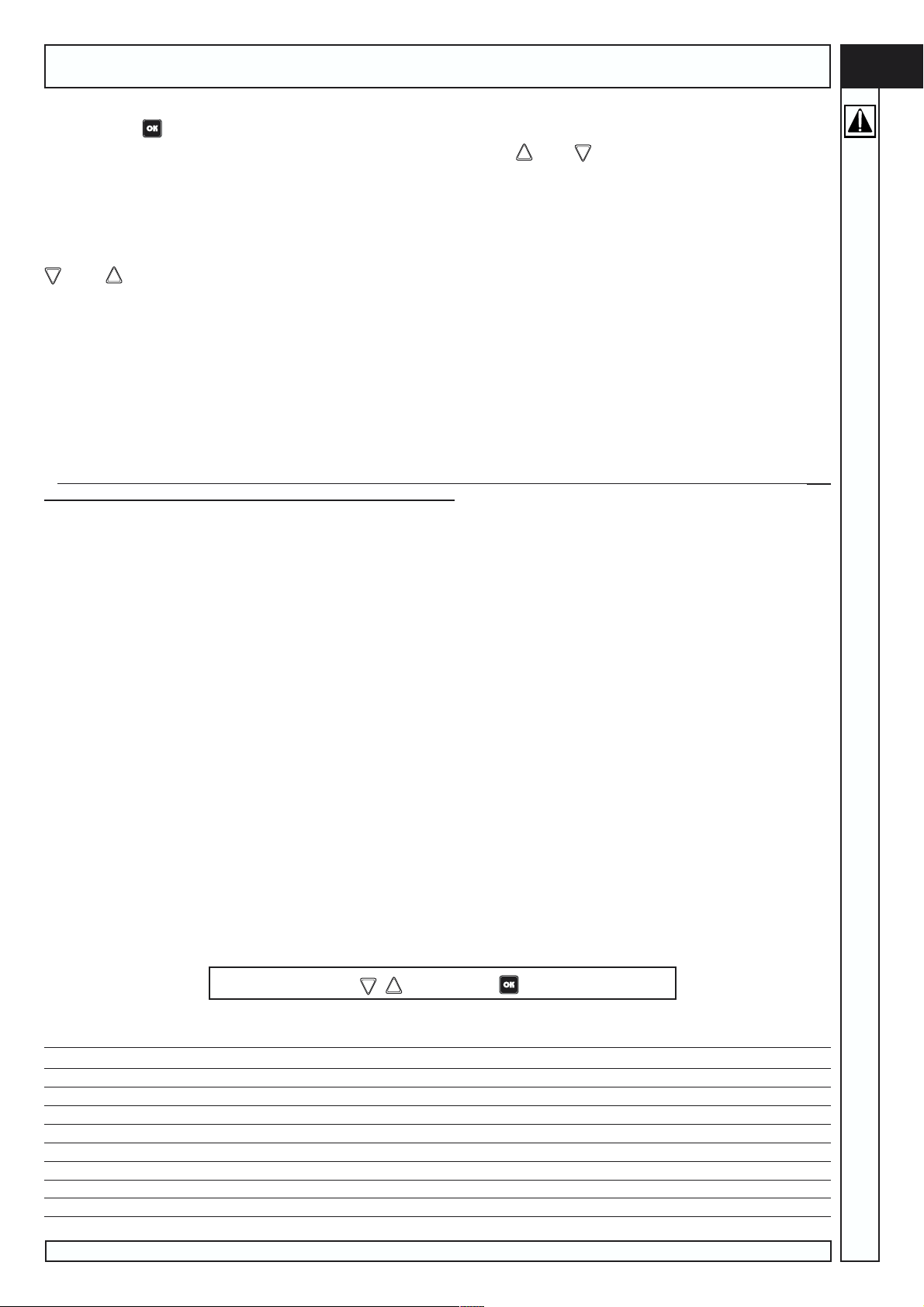
MODIFIABLE PARAMETERS
Pressing the key with the machine OFF, the operating parameters menu will be displayed; in certain cases a password
is required in order to make changes. The menu is scrolled using the keys and .
0) control unit ID (service password): selects the identification code of the control unit; if several compressors are connected
to the same RS485 line, multiple IDs can be selected.
1) Pre-alarm time lapse (service password): each hour of operation clocked by the machine is counted down automatically;
when the count reaches 0, the control unit trips a Maintenance alarm.
The count, preceded by a minus sign (-), indicates how many hours have elapsed since the last maintenance alarm; the keys
and can be used to set a new value (entering the new value has the effect of overriding the previous alarm).
2) Alarm history (no password required): this menu can be used to display the 30 most recent alarms.
3) Pre-alarm temperature (factory password): this menu is used to set the delta temperature (delta, in °C) referred to the
maximum alarm temperature; the value can be set between 1 and 20.
Example: if the maximum temperature is 120 °C and the differential is 10 °C, the maximum temperature pre-alarm will trip at 110 °C.
4) Maximum temperature (factory password): this menu is used to set the maximum permissible temperature; the adjustment
range is 0 to 150 °C.
5) Minimum temperature (factory password): this menu is used to set the minimum temperature; the adjustment range is 0 to -14 °C.
7) Duration of loadless operation (service password): this menu is used to change the duration of the no-load cycle; the range
of adjustment is 1 to 250 seconds.
8) Auto start (service password): this parameter enables automatic Start; if activated, the compressor will restart automatically
following an electrical power supply failure.
If the compressor starts up unexpectedly, persons happening to be nearby could be harmed or injured. With this in mind, use
of the automatic start function is not generally recommended.
9) Internal phase sequence (service password): this parameter enables control of the phase sequence internally, or disables
internal control and activates the phase sequence control input at the terminals.
10) Language (no password required): this parameter is used to select the language in which messages are displayed; there
are 5 available (English, French, German, Italian, Spanish).
11) Enable RS485 (no password required): this parameter is used to enable data transmission using RS485, and automatically
disable transmission on RS232.
12) Pressure sensor (service password): enables the 4-20 mA input to which the pressure sensor is connected. With this
parameter activated, the pressure measurement is displayed. To display machine operation time, press the key; the display will
revert to the pressure measurement automatically after 20 seconds.
Enabling this parameter, the external pressure switch contact changes function and becomes an input for the oil separator
minimum pressure switch; in this situation, the compressor is prevented from restarting if pressure in the oil separator is high.
13) PSI/BAR (no password required): selects the unit of measure used to display pressure.
14) No-Load/operating pressure set point (no password required): this parameter is used to set the pressure at which the
compressor must switch off; if inverter drive is enabled, it indicates the operating pressure at which the inverter will begin modulating
output to maintain the pressure steady.
15) Load/operating Delta set point (no password required): indicates the pressure at which the control unit enables compressor
restart.
For example, if the set differential value is 1 bar and maximum operating pressure is 9 bar, this means that the compressor will
switch off at 9.5 bar and switch on again at 8.5 bar.
16) Maximum pressure (service password): this parameter sets the maximum pressure value permissible in operation, i.e. the
maximum pressure of point 14.
17) Maximum alarm pressure (factory password): this parameter sets the maximum pressure value at which an alarm is
tripped in the control unit.
18) Remote pressure(service password): enabling this parameter, the pressure and the relative alarms continue to be displayed,
but the compressor starting sequence is controlled from an external pressure switch contact.
19) Load delay(factory password): this parameter sets the delay, in seconds, from the moment when the starting cycle terminates
to the moment when the air solenoid valve energizes.
GB
ALWAYS HIT KEYS
MODIFIABLE PARAMETERS
Oil temperature pre-alarm (differential)
Maximum oil temperature
Minimum oil temperature
No-load (EMPTY) time
Maintenance pre-alarm
Automatic start
Pressure sensor
PSI/BAR
°C
°C
°C
sec.
Hours
Min.
0
0
-14
1
0
YES
YES
PSI
AND PRESS TO CONFIRM ENTRY
Max.
Standard
20
150
0
250
32768
NO
NO
BAR
5
110
-7
20
3000
NO
YES
BAR
No-Load/operating pressure set point
Load/pressure differential set point
Maximum permissible pressure
Maximun alarm pressure
Load (CHARGED) delay
Internal phase sequence control
Language
Display contrast level
Enable RS485
Rotar Plus 20-25 Easytronic - Cod.197AA2702 - Edition 00 01/2004
bar
bar
bar
bar
sec.
Min.
0
0
0
0
0
YES
1
SI
Max.
15
15
15
16
200
NO
20
NO
Standard
10
8,5
11
13
10
YES
ITA
5
SI
7
Page 8
GB
CONTROL FUNCTIONS
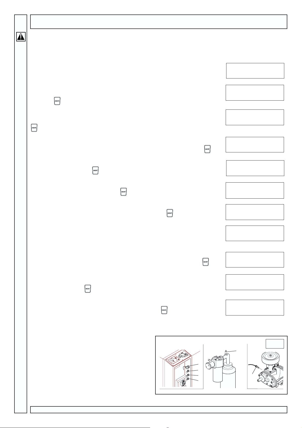
ALARM MESSAGES
In the event of a fault occurring or of set safety limits being exceeded, the red alarm light will appear and the current alarm
condition is displayed.
1) Check direction of rotation
Alarm trips in the event of incorrect phase sequence being detected. The compressor locks
up; to restore operation, the correct phase sequence must first be re-established.
NOTE: To reset the alarm, the equipment must be isolated from the a.c. power supply.
2) Check temperature sensor
Alarm trips in the event of temperature sensor fault (sensor open or short circuiting). The
compressor locks up; to restore operation, check the connection and/or replace the sensor,
then press
3) Maximum oil temperature
Alarm trips when the maximum oil temperature is sensed. The compressor locks up; to
restore operation, wait for the temperature to fall below the programmed value, then press
.
4) Minimum oil temperature
Alarm trips when the minimum oil temperature is sensed. The compressor locks up; to restore
operation, wait for the temperature to rise above the programmed value, then press
5) Oil temperature pre-alarm
Trips when the pre-alarm oil temperature is sensed. The compressor does not lock up. To
override the pre-alarm, press
6) Motor thermal overload
Operates when the thermal overload relay is tripped. The compressor locks up. To silence
the alarm, first verify the cause, then press
7) Emergency
A circuit activates to lock up the compressor when the red emergency button is depressed.
To silence the alarm, first reset the emergency button, then press
8) Machine maintenance pre-alarm
Trips to warn the user than that machine is due for routine maintenance (oil change, service
filters, etc.). The alarm must be silenced by the service technician, who when carrying out
maintenance operations will select the item Pre-alarm hours from the menu and reset the
value as described under the heading Modifiable parameters - point (1).
9) Separator pressure switch
Alarm trips in the event of the separator pressure switch contact opening. The compressor
locks up. To silence the alarm, first reset the separator pressure switch, then press
10) 4-20 mA fault (pressure sensor)
Alarm trips when the pressure sensor connected to the 4-20mA input does not operate
correctly. The compressor locks up. To silence the alarm, first restore the pressure switch to
normal status, then press
11) Maximum pressure
Alarm trips when the maximum pressure setting is exceeded. The compressor locks up. To
silence the alarm, first restore the correct pressure, then press
.
.
.
.
.
.
.
.
Display status
30°C h00110 m05
Wrong rotation
30°C h00110 m05
Temp sensor faulty
110°C h00110 m05
Max oil temp
-10°C h00110 m05
Min oil temp
105°C h00110 m05
Oil temp pre-alarm
74°C h00110 m05
Motor thermal relay
74°C h00110 m05
Emergency button
74°C h00110 m05
Routine maintenance
75°C h00110 m05
Separator p/switch
74°C h00110 m05
4-20mA fault
74°C h00110 m05
Max pressure
SAFETY DEVICES (FIG. 5)
1) Electronic transducer: controls both STOP and START
pressure.
2) Pressure switch for oil separator filter clogging:
indicates efficiency limit of oil separator filter.
3) Minimum pressure switch:
4) Pressure switch for air filter clogging: indicates air filter
efficiency limit
5) Safety valve: opens the air bleeding unit when the
safety value is reached.
6) Max. temperature sensor: stops motor over +110°C.
8
Rotar Plus 20-25 Easytronic - Cod.197AA2702 - Edition 00 01/2004
5
5
1
2
3
4
6
Page 9
1
2
3
4
5
6
7
8
9
10
11
12
13
14
15
16
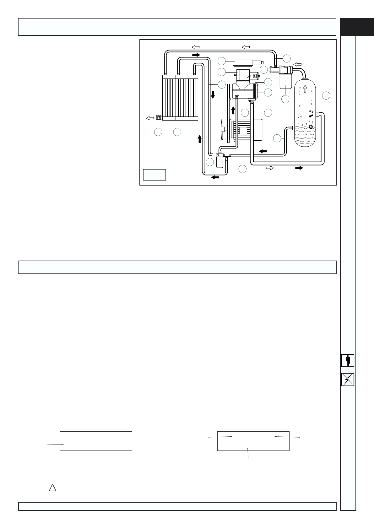
OPERATION
OPERATING CYCLE
At first start-up, the motor starts in the
star configuration. In this phase the compressor
starts slowly, the solenoid valve (1) is open and
the suction regulator (2) is closed.
The compressor remains in this condition
for about 5÷7 seconds
After this time, the motor is powered by
the delta configured circuit. The solenoid valve (1) receives current and closes allowing the
opening of the suction regulator (2), which
intakes atmospheric air through the filter (3).
At this stage, the compressor runs at full
speed and begins to compress the air in the tank
(6).
The compressed air cannot come out
from the minimum pressure valve set at 3÷4 bar.
The compressed air compresses the oil
in the tank (6) and forces it to flow towards the
tube (7).
If the oil temperature is below 71°C the
oil from the tube (7) flows directly to the
compressor (4) through the tube (8) passing through the filter (9).
If the oil temperature exceeds 71°C the thermal expansion valve shuts down the ducting to tube (8) and oil flows to the
radiator (11) through the tube (10). Once cooled, oil flows back to the compressor through tubes (12) and (8) and filter (9).
The oil reaches the compressor (4) mixing with the intake air and creating an air/oil mixture which ensures the seal and the
lubrication of the moving parts of the compressor.
The air/oil mixture returns to the tank (6) where the air is pre-separated through spinning and is finally separated from the
oil by the oil separator filter (13).
From the tank (6) only air comes out, which reaches the radiator (11) through the tube (15) and the mains through the cutoff cock (16).
6
GB
START-UP
FIRST START-UP
Before starting the machine up for the first time, make sure that:
the mains voltage is the same as the voltage on the CE plate;
the electric connections have been made using cables of proper cross-section;
the (wall) main power switch has suitable fuses;
the oil level is over the minimum level - top up with the same type of oil if necessary (Shell Corena D46);
the air outlet cock is completely open.
CONNECT THE TANK WITH A HOSE.
Only specialized technicians can start the compressor (on-site testing) for the first time.
If the machine does not start and the display shows the alarm message Wrong direction of rotation, proceed as
follows:
break power supply through the wall switch;
open the electric box door and reverse the two phases in the terminal board;
close the door, power on and start the machine.
Display status during compressor operation
Display status at start (shown for 5 seconds) Display status during normal operation
software
release
Easy Tronic II
V.0.0.0 GG/MM/AA
date
oil temp.
100°C 9.5Bar
Status=stand-by
pressure
Press the key to see hours and minutes operation; the information is displayed for 20 seconds.
Rotar Plus 20-25 Easytronic - Cod.197AA2702 - Edition 00 01/2004
compressor
status
9
Page 10
GB
MAINTENANCE
BEFORE MAINTAINING THE MACHINE ALWAYS PERFORM THE FOLLOWING
Switch off the motor by means of the switch on the control panel.
Power the machine off by means of the wall outer switch (do not press the emergency stop button).
Close the line cock.
Make sure that no compressed air is inside the oil separator tank by turning the cock anticlockwise and bleed all air off.
Before removing any protections, double check that wall-mounted switch has been turned to 0.
AFTER THE FIRST 100 HOURS
1) Check the oil level (see next paragraph): top up with the same type of oil if
necessary.
2) Check for proper screw tightening: in particular the power electric connection
screws.
3) Visually check that all fittings seal properly.
4) Check room temperature
EVERY 500 HOURS
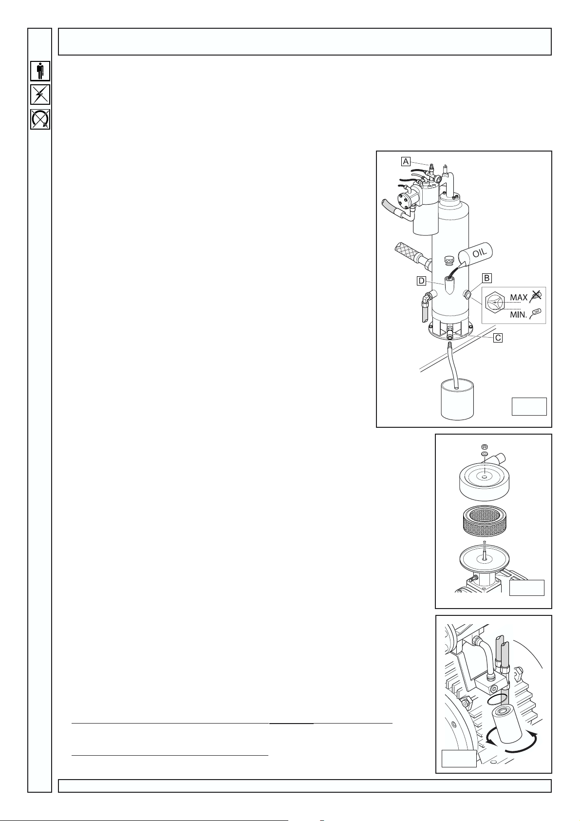
Check the oil level (fig.7)
Always blow off air from the oil separator tank before topping up. Slowly unscrew
the cock A until all air comes out and then screw it again.
The max. level is reached when the oil touches the filler.
Check level at oil light (B).
The amount of oil necessary for topping up from the minimum level to the
maximum level is about 1.5 lt.
EVERY 1000 HOURS
Clean the air filter thoroughly (fig.8). Blow filter with compressed air from
inside out.
Hold the filter against the light and look for any tears. Always replace a torn
filter. Install filter cartridge and cover accurately. If badly positioned, they would let
dust into the compression unit.
Replace the air filter when you have cleaned it four times.
Clean the radiators
The radiator is highly efficient with a limited clogging degree. However, in case
of abnormal overheating or at least once a year, a check for filter clogging is recommended.
To clean the radiators, proceed as follows:
remove the rear and upper panels of the pressurized chamber;
position a protection plastic sheet under the radiator unit;
spray (spray gun + solvent) from the outside towards the inside;
check for proper air flow through the radiators.
AFTER THE FIRST 1000 HOURS, EVERY 3000 HOURS AFTERWARDS
Change oil (fig.7)
Change oil every 3000 working hours when compressor is hot over 70 °C.
Drain pressure from the oil separator tank through cock (A).
Connect the supplied hose to cock (C).
Unscrew filler cap, open ball cock (C) and drain all oil into a container. When finished,
close the cock and remove the hose.
Fill fresh oil through filler plug (D) (a full charge is 6 liters).
Close the plug.
Power on machine.
Start machine and let is run for 5 minutes, then stop it.
Drain all air.
Allow 3 minutes and check oil level. Top up if needed.
7
8
10
When you change oil, you can change to a different type of lubricant (see table).
SHELL CORENA D AGIP DICREA 46
IP VERETUM OIL 46 BP ENERGOL HLP 46
MOBIL D.T.E. MEDIUM CASTROL AIRCOL MR46
ESSO UNIVIS 46 FINA EOLAN R046
Remember to use the same oil for future top-ups - Never mix different types of oil
Change oil filter (fig.9)
Change oil filter EVERY TIME YOU CHANGE OIL; depressurize tank before proceeding.
Always smear filter edge and filter seal lightly with oil before screwing filter into place by hand.
Rotar Plus 20-25 Easytronic - Cod.197AA2702 - Edition 00 01/2004
9
Page 11
1
Test
MAINTENANCE
DRAINED OIL IS A POLLUTANT!
Dispose of according to the environmental protection rules in force.
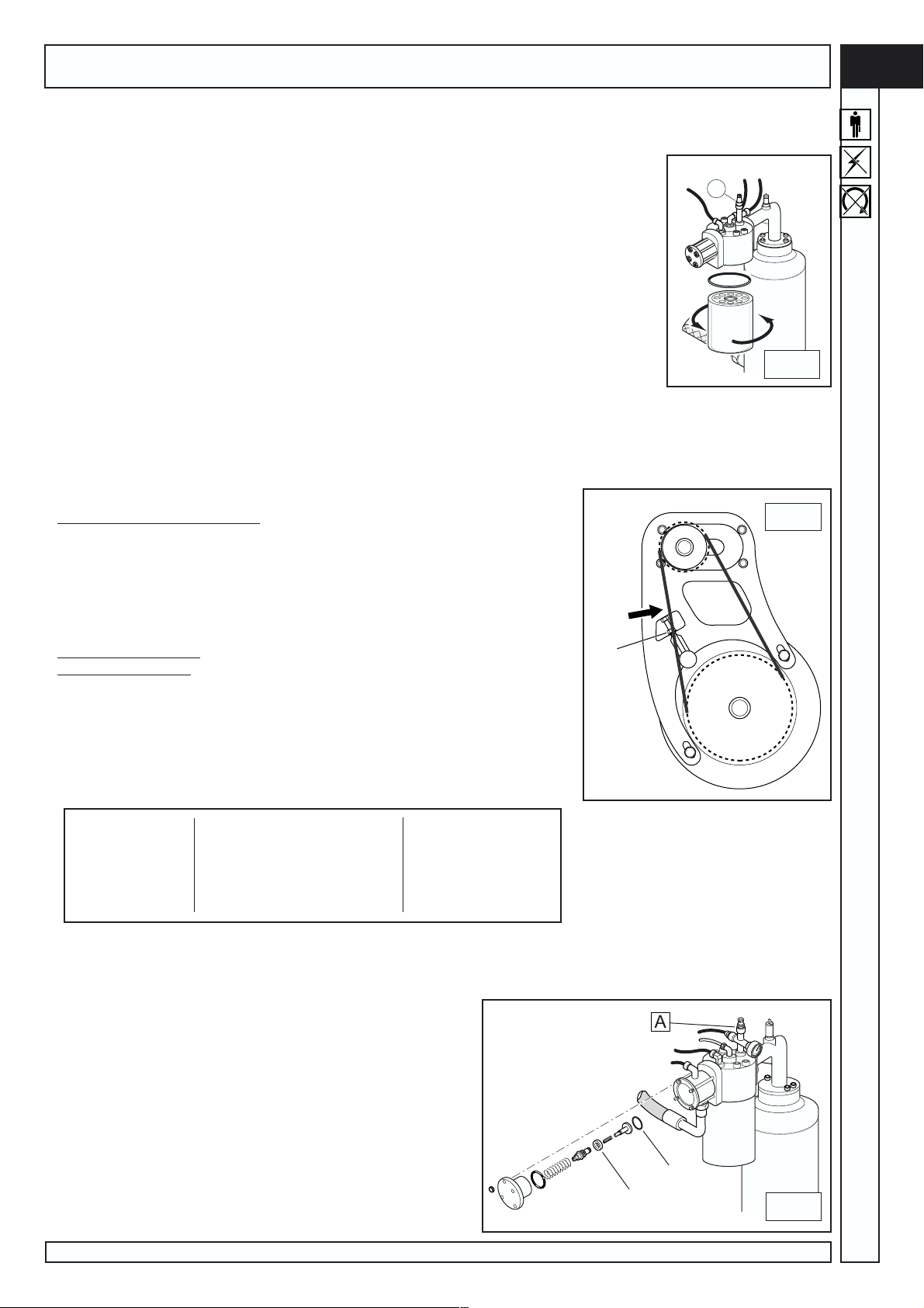
Change the oil separator filter (fig.10)
The oil separator is not washable and should be changed at each oil change. Never exceed 3000
operating hours.
Drain all compressed air through cock (A).
Unscrew the filter manually (use a special tool for filters, if needed). Rotate counter clockwise
to unscrew.
Fit a new filter. Screw new filter in clockwise. Smear the gasket of O-ring inside the oil separator
filter lightly with oil before fitting the filter.
Drain the condensate (fig.7)
Air/oil mixture cooling is set to occur below air dew point, however, it is impossible to avoid conden-
sate in oil totally.
Once a month, drain condensate before starting the compressor: open cock (C) and close it as
soon as oil start flowing out instead of water.
Always make sure the oil separator tank is depressurized before proceeding. Drain any
pressure through cock (A).
Check oil level and top up if needed.
CONDENSATE IS A POLLUTANT! Do not drain into the sewers. Dispose of according to the environmental protection rules in
force.
EVERY 2000 OPERATING HOURS
Check drive belt tension (Fig.12)
Use a frequency tester to carry out this check.
Proceed as follows:
Move tester microphone closer to the belt about at mid length and hit the belt
with a wrench.
Read value on tester. Stretch or slacken the belt if the value is different from
values indicated in the table:
A
10
12
GB
Higher value = slacken
Lower value = stretch
To adjust, proceed as follows:
turn the screw (1) anti-clockwise to stretch the belt and clockwise to slacken.
check frequency value once again. Repeat the above procedure, if necessary, to
reach optimal value.
When finished, re-assemble cabinet parts before starting the compressor.
V 400 / Hz 50 V 400 / Hz 60
Rotar Plus 20 2008 2010 2013 2008 2010
frequency (Hz) 71 73 68 72 71
Rotar Plus 25 2508 2510 2513 2508 2510
frequency (Hz) 79 78 75 81 77
EVERY 12000 HOURS
Minimum pressure valve (fig.11)
Close the mains cock and drain all air from the oil separator tank
through valve (A)
Remove the flange fixing nuts and lift the flange
Change the seals (1) and (2).
Changing the hoses
Loosen the hose fittings, change hose and tighten fittings securely.
Proceed with the last steps of the oil change procedure.
Changing electric motor bearings.
This can also be done after 15,000 operating hours. Have wear
condition of bearings assessed by a specialized technician.
2
1
Rotar Plus 20-25 Easytronic - Cod.197AA2702 - Edition 00 01/2004
11
11
Page 12
GB
1
Test
MAINTENANCE
EVERY 20000 HOURS
Change:
Compressor seal ring
Tank safety valve
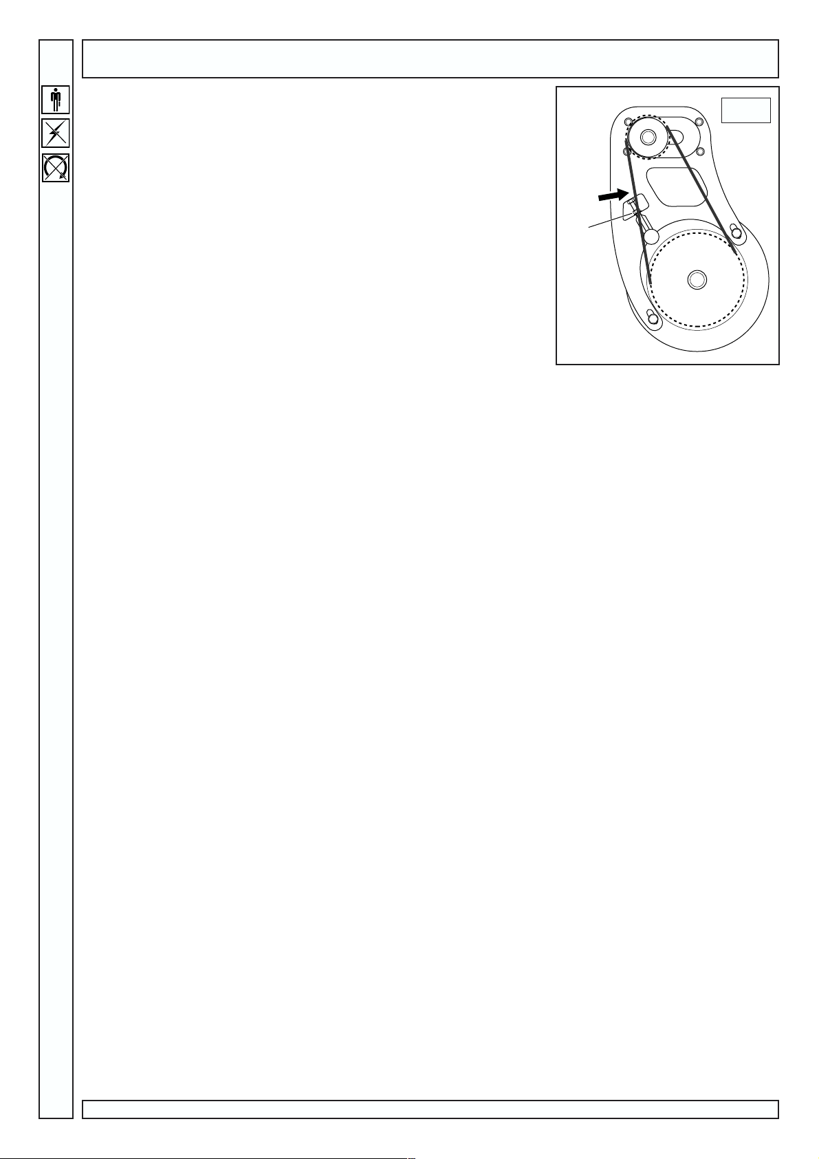
Change the drive belt as follows (fig.12):.
2) Tighten the screw (1) turning it clockwise with a hexagon head wrench, until you
feel that the belt is slackening and comes off easily.
3) Install the new belt and set the screw (1) back to its original position (turn clockwise).
Leave belt slightly slack.
Check frequency value as described on page 11.
12
12
Rotar Plus 20-25 Easytronic - Cod.197AA2702 - Edition 00 01/2004
Page 13

TROUBLESHOOTING
GB
Problem
Motor stop due to thermal relay
tripping
High oil consumption
Oil leakage from suction filter
Safety valve open
Compressor temperature thermostat tripped
Cause
Voltage too low
Overtemperature
Defective drainage
Oil level too high
Oil separator filter broken
Oil separator filter seals leaking
Suction regulator does not close
Pressure too high
Suction regulator does not close
at the end of the cycleI
Oil separator filter clogged
Room temperature too high
Radiator clogged
Oil level too low
Thermostat faulty
Remedy
Check voltage, press Reset and start once again
Check motor absorption and check relay settings. If absorption is
OK, press Reset and start once again
Check oil drainage tube and non-return valve
Check oil level and drain some, if necessary
Change oil separator filter
Replace gaskets
Check regulator and solenoid valve
Check setting of pressure switch
Check regulator and solenoid valve
Change oil separator filter
Improve ventilation
Clean the radiator with solvent
Top up with oil
Replace thermostat, press Reset and start once again
Low compressor efficiency
The compressor is running but
does not compress air
The compressor compresses air
beyond set max. pressure
Compressor does not restart
Difficult start
Oil inside cabinet
Belt is slack
Air filter dirty or clogged
Regulator is closed and does not
open because it is dirty
Regulator is closed and does not
open because it receives no command signal
Regulator is open and does not
close because it is dirty
Regulator is open and does not
close because it receives no
command signal
Oil separator filter clogged
Min. pressure valve does not close perfectly
Voltage too low
Shop too cold
Leakage from tubes
Leakage from front compressor
flange
Stretch the belt, press Reset and start once again
Clean or replace filter
Remove the suction filter and check if regulator can be manually
opened. Remove and clean, if necessary.
Ensure that signal between pressure switch and solenoid valve is
available. Replace part, if damaged.
Remove the regulator and clean
Ensure that signal between pressure switch and solenoid valve is
available. Replace part, if damaged.
Change oil separator filter
Remove and clean the valve. Replace the seal, if necessary
Check mains voltage
Heat up shop
Tighten fittings and/or replace damaged tubes
Remove and replace seal ring.
Rotar Plus 20-25 Easytronic - Cod.197AA2702 - Edition 00 01/2004
13
Page 14
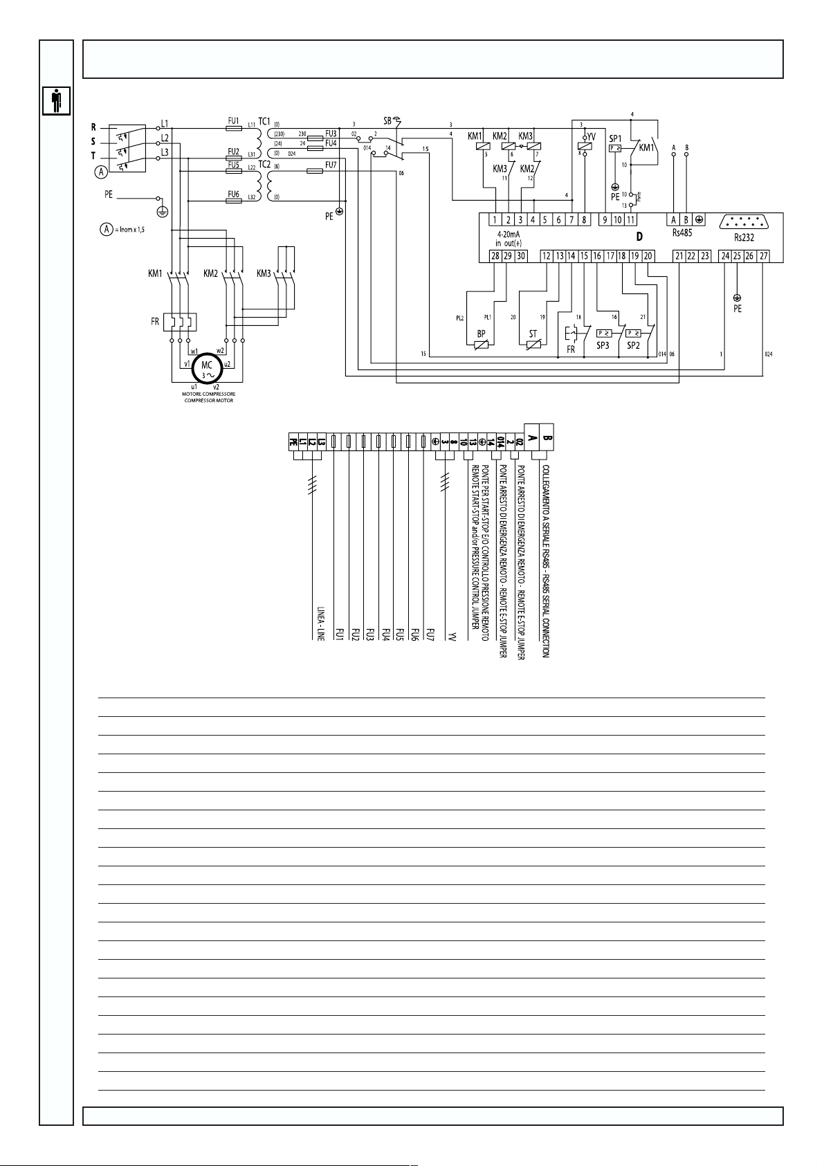
GB
WIRING DIAGRAM
20 hp 25hp
230V 400V 230V 400V
TC1 Transformer 150AV
TC2 Transformer
SB Emergency button
FU1-FU2 Fuses 6.3x32 4A 500V
FU3 Fuses 6.3x32 1.6A 500V
FU4-FU5-FU6 Fuses 6.3x32 1A 500V
FU7 Fuses 6.3x32 500 mA 500V
KM1 Line contactor 18,5 kW (*) 11 kW(*) 18,5 kW (*) 11 kW(*)
KM2 Delta contactor 18,5 kW (*) 11 kW(*) 18,5 kW (*) 11 kW(*)
KM3 Star contactor 15 kW (*) 7,5 kW(*) 15 kW (*) 7,5 kW(*)
FR Thermal relay (28-40) (17-22) (28-40) (20-25)
YV Solenoid valve
SP1 Minimum pressure switch
SP2 Pressure switch for oil separator filter
SP3 Pressure switch for air filter
BP Pressure transducer 0-16 bar
D Electronic controller
ST Thermal feeler for electronic controller
Motor cable cross-section (sq mm) 7x10 7x4 7x10 7x6
(*) = 400V AC3
14
Rotar Plus 20-25 Easytronic - Cod.197AA2702 - Edition 00 01/2004
 Loading...