

Page 1

7425MUM041_EN_2008-06
- EN -
USER’S,
MAINTENANCE MANUAL
RD
RD RD
RD 185
185185
185 ---- 810
810810
810
ISSUE
2008
Targhetta Dati
REFRIGERATED AIR DRYER
Page 2

Fini S.p.a.
Via F.lli Vignoli,3 40069 Zola Predosa – Bologna – ITALY
IT - Dichiara sotto la sua esclusiva responsabilità,che il
prodotto qui di seguito descritto è conforme alle prescrizioni
di sicurezza delle direttive: 98/37/CE, 97/23/CE,
73/23/CEE, 89/336/CEE
FI - vakuuttaa, että seuraavassa esitelty tuote vastaa alla
lueteltujen direktiivien turvallisuusvaatimuksia:
98/37/EC, 97/23/EC, 73/23/EEC, 89/336/EEC
EN - Declares under its sole responsibility that the
product described below complies with the safety
requirements of directives:
98/37/EC, 97/23/EC, 73/23/EEC, 89/336/EEC
EL - ∆ηλώνει µε αποκλειστικά δική του ευθύνη ότι το προϊόν
που περιγράφεται παρακάτω ανταποκρίνεται στις
προδιαγραφές ασφαλείας των οδηγιών: 98/37/EE, 97/23/EE,
73/23/EEC, 89/336/EEC
FR - Déclare sous son entière responsabilité que le produit
décrit ci-après est conforme aux prescriptions de sécurité
des directives :
98/37/CE, 97/23/CE, 73/23/CEE, 89/336/CEE
PL - oświadcza pod wyłączną własną odpowiedzialnością, Ŝe
opisany poniŜej wyrób odpowiada wymaganiom dotyczącym
bezpieczeństwa zawartym w Dyrektywach 98/37/EC,
97/23/EC, 73/23/EC, 89/336/EC
DE - erklärt unter ihrer alleinigen Verantwortung, dass das
in Folge beschriebene Produkt den Sicherheitsvorschriften
der folgenden Richtlinien entspricht:
98/37/EG, 97/23/EG, 73/23/EWG, 89/336/EWG
CS - prohlašuje s plnou odpovědností, že uvedený výrobek
vyhovuje bezpečnostním požadavkům směrnic:
98/37/ЕS, 97/23/ЕS,73/23/ЕHS, 89/336/ЕHS
ES - Declara bajo su exclusiva responsabilidad que el
producto descrito a continuación responde a las
prescripciones de seguridad de las directivas :
98/37/CE, 97/23/CE, 73/23/CEE, 89/336/CEE
SK - Zodpovedne vyhlásuje, že uvedený výrobok zodpovedá
bezpečnostným požiadavkám smerníc:
98/37/ES, 97/23/ES, 73/23/EES, 89/336/EES
NE - Verklaart onder zijn eigen verantwoordelijkheid dat het
hieronder beschreven product in overeenstemming is met
de veiligheidsvoorschriften van de richtlijnen:
98/37/EG, 97/23/EG, 73/23/EEG, 89/336/EEG
HU - teljes felelısségének tudatában tanúsítja, hogy az
alábbiakban jellemzett termék a 98/37/ЕС, 97/23/ЕС,
73/23/ЕЭС és 89/336/ЕЭС sz. irányelvek biztonsági
követelményeinek megfelel.
N0 -
Erklærer under eget ansvar at produktet her beskrevet
er i overensstemmelse med sikkerhetsforskriftene i
direktivene:
98/37/EC, 97/23/EC, 73/23/EEC, 89/336/EEC
LT - Su visa atsakomybe pareiškia, kad žemiau aprašytas
gaminys atitinka direktyvų 98/37/ES, 97/23/ES, 73/23/EES ir
89/336/EES saugumo reikalavimams.
SV - Försäkrar under eget ansvar att den produkt som
beskrivs följande är i överensstämmelse med
säkerhetsföreskrifterna i EU-direktiv:
98/37/EG, 97/23/EG, 73/23/EEG, 89/336/EEG
LV - Apliecina, uzĦemoties pilnu atbildību, ka zemāk
aprakstītais produkts atbilst direktīvu 98/37/ЕС, 97/23/ЕС,
73/23/ЕEС un 89/336/ЕEС drošības noteikumiem.
DA - Forsikrer på eget ansvar, at produktet, der beskrives
nedenfor, er i overensstemmelse med
sikkerhedsforskrifterne i direktiverne:
98/37/EC, 97/23/EC, 73/23/EEC, 89/336/EEC
ET - Deklareerib omal vastutusel, et allpool kirjeldatud toode
vastab direktiivide 98/37/EÜ, 97/23/EÜ, 73/23/EMÜ ja
89/336/EMÜ ohutusnõuetele.
PT - Declara sob a sua exclusiva responsabilidade que o
produto descrito a seguir está em conformidade com as
prescrições de segurança das directivas:
98/37/CE, 97/23/CE, 73/23/CEE, 89/336/CEE
SL - Na lastno odgovornost izjavlja, da je spodaj opisani
izdelek v skladu z varnostnimi predpisi, ki veljajo za stroje
98/37/EU, 97/23/EU, 73/23/EEU in 89/336/EEU.
Amministratore delegato Toimitusjohtaja
CEO Dieuqu/nwn Su/mbouloj
PdG Dyrektor Zarządzający
Geschäftsführer Generální ředitel
Administrador delegado Generálny riaditeľ
President-directeur Vezérigazgató
Daglig leder Generalinis direktorius
Verkställande direktör Āenerāldirektor
Administrerende direktør Pea direktor
Administrador delegado Generalni direktor
Enrico Santoro
Page 3
Dear Customer,
thank you for choosing our product. In order to get the best performances out of this product, please read
this manual carefully.
To avoid incorrect operation of the equipment and possible physical risk to the operator, please read and
strictly follow the instructions contained in this manual.
Note, these instructions are in addition to the safety rules that apply in the country where the dryer is
installed. Before packing for shipment each RD series refrigerated air dryer undergoes a rigorous test to
ensure the absence of any manufacturing faults and to demonstrate that the device can perform all the
functions for which it has been designed.
Once the dryer has been properly installed according to the instructions in this manual, it will be ready for
use without any further adjustment. The operation is fully automatic, and the maintenance is limited to few
controls and some cleaning operations, as detailed in the following chapters.
This manual must be maintained available in any moment for future references and it has to be intended as
inherent part of the relevant dryer.
Due to the continuous technical evolution, we reserve the right to introduce any necessary change without
giving previous notice.
Should you experience any trouble, or for further information, please do not hesitate to contact us.
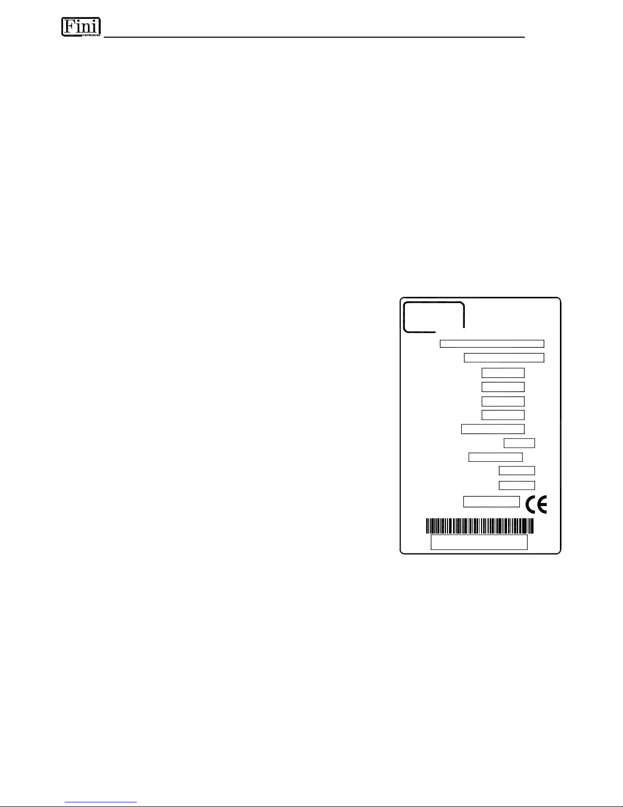
DATA NAMEPLATE
Model
Serial No.
Code
Nominal Flow Rate
Max Air Pressure
Max Inlet Air Temp.
Ambient Temp.
Refrigerant (Type and qty)
Refrig. Design Pres. HP/LP
Electric Supply
Electric Nominal Power
Fuse Max.
Manufactured
The data nameplate is located on
the back of the dryer and shows
all the primary data of the
machine. Upon installation, fill in
the table on the previous page
with all the data shown on the
data nameplate. This data should
always be referred to when
calling the manufacturer or
distributor.
The removal or alteration of the
data nameplate will void the
warranty rights.
Model
Serial No.
Nominal Flow Rate
Max Air Pressure
Max Inlet Air Temp.
Ambient Temp.
Refrigerant
Refrig. Design Pres.
HP/LP
Electric Supply
Electric Nominal Power
Fuse Max.
Manufactured
Nl/min
barg
°C
°C
type/kg
barg
ph/V/Hz
W/A
A
www.finicompressors.com
BOLOGNA - ITALY
40069 - ZOLA PREDOSA
FINI S.p.A.
Fini
COMPRESSORS
WARRANTY CONDITIONS
For 12 months from the installation date, but no longer than 14 months from the delivery date, the warranty
covers eventual faulty parts, which will be repaired or replaced free of charge, except the travel, hotel and
restaurant expenses of our engineer.
The warranty doesn’t cover any responsibility for direct or indirect damages to persons, animals or
equipment caused by improper usage or maintenance, and it’s limited to manufacturing faults only.
The right to warranty repairs is subordinated to the strict compliance with the installation, use and
maintenance instructions contained in this manual.
The warranty will be immediately voided in case of even small changes or alterations to the dryer. To
require repairs during the warranty period, the data reported on the identification plate must be notified.
Page 4

1. SAFETY RULES
1.1 Definition of the Conventional Signs Used in This Manual
1.2 Warnings
1.3 Proper Use of the Dryer
1.4 Instructions for the use of pressure equipment according to PED Directive 97/23/EC
2. INSTALLATION
2.1 Transport
2.2 Storage
2.3 Installation site
2.4 Installation layout
2.5 Correction factors
2.6 Connection to the Compressed Air System
2.7 Connection to the Cooling Water Network (Water-Cooled)
2.8 Electrical connections
2.9 Condensate Drain
3. START UP
3.1 Preliminary Operations
3.2 First Start Up
3.3 Start-up and shut down
4. TECHNICAL CHARACTERISTICS
4.1 Technical Specifications RD 185-810 /AC (Air-Cooled)
4.2 Technical Specifications RD 185-810 /WC (Water-Cooled)
5. TECHNICAL DESCRIPTION
5.1 Control panel
5.2 Operation
5.3 Flow Diagram (Air-Cooled)
5.4 Flow Diagram (Water-Cooled)
5.5 Refrigerating compressor
5.6 Condenser (Air-Cooled)
5.7 Condenser (Water-Cooled)
5.8 Condenser water regulating valve (Water-Cooled)
5.9 Filter Drier
5.10 Capillary tube
5.11 Alu-Dry Module
5.12 Hot gas by-pass valve
5.13 Refrigerant Pressure Switches PA-PB-PV
5.14 Safety thermo-switch Ts
5.15 Compressor crankcase heater
5.16 DMC14 Electronic Instrument
5.17 DMC20 Electronic Instrument
5.18 Electronic level drain
6. MAINTENANCE, TROUBLESHOOTING AND DISMANTLING
6.1 Controls and Maintenance
6.2 Troubleshooting
6.3 Maintenance operation on the refrigeration circuit.
6.4 Dismantling of the Dryer
7. LIST OF ATTACHMENTS
7.1 Dryers Dimensions
7.2 Exploded View
7.3 Electrical Diagram
Page 5

1.1 DEFINITION OF THE CONVENTIONAL SIGNS USED IN THIS MANUAL
Carefully read instruction manual before attempting any service or maintenance procedures on the
dryer.
Caution warning sign. Risk of danger or possibility of damage to equipment, if related text is not
followed properly.
Electrical hazard. Warning message indicates practices or procedures that could result in personal
injury or fatality if not followed correctly.
Danger hazard. Part or system under pressure.
Danger hazard. High temperature conditions exist during operation of system. Avoid contact until
system or component has dissipated heat.
Danger hazard. Treated air is not suitable for breathing purposes; serious injury or fatality may
result if precautions are not followed.
Danger hazard: In case of fire, use an approved fire extinguisher, water is not an acceptable
means in cases of fire.
Danger hazard. Do not operate equipment with panels removed.
Maintenance or control operation to be performed by qualified personnel only 1.
ARIA
AIR
LUFT
AIR
Compressed air inlet connection point.
ARIA
AIR
LUFT
AIR
Compressed air outlet connection point.
Condensate drain connection point.
Cooling water inlet connection point (Water-Cooled).
Cooling water outlet connection point (Water-Cooled).
Operations which can be worked out by the operator of the machine, if qualified
1.
NOTE : Text that specifies items of note to be taken into account does not involve safety precautions.
In designing this unit a lot of care has been devoted to the environment protection:
• CFC free refrigerants
• CFC free insulation parts
• Energy saving design
• Limited acoustic emission
• Dryer and relevant packaging composed of recyclable materials
Not to spoil our commitment, the user should follow the few ecological suggestions marked with
this sign.
1 Experienced and trained personnel acquainted with the relevant rules and laws, capable to perform the needed activities and to identify and
avoid possible dangerous situations while handling, installing, using and servicing the machine.
Page 6

1.2 WARNINGS
Compressed air is a highly hazardous energy source. Never work on the dryer with parts under
pressure. Never point the compressed air or the condensate drain jet towards anybody. The user is
responsible for the installation of the dryer, which has to be executed on the basis of the instructions
given in the “Installation” chapter. Otherwise, the warranty will be voided and dangerous situations
for the personnel and/or damages to the machine could occur.
Only qualified personnel are authorized to service electrically powered devices. Before attempting
maintenance, the following conditions must be satisfied:
• Ensure that main power is off, machine is locked out, tagged for service and power cannot be
restored during service operations.
• Ensure that valves are shut and the air circuit is at atmospheric pressure. De-pressurize the dryer.
These refrigeration air dryers contain R134a or R404A HFC type refrigerant fluid. Refer to the
specific paragraph for maintenance operation on the refrigeration circuit – maintenance operation
on the refrigeration circuit.
Warranty does not apply to any unit damaged by accident, modification, misuse, negligence or
misapplication. Unauthorized alterations will immediately void the warranty.
In case of fire, use an approved fire extinguisher, water is not an acceptable means in cases of
electrical fire.
1.3 PROPER USE OF THE DRYER
This dryer has been designed, manufactured and tested for the purpose of separating the humidity normally
contained in compressed air. Any other use has to be considered improper.
The Manufacturer will not be responsible for any problem arising from improper use; the user will bear
responsibility for any resulting damage.
Moreover, the correct use requires the adherence to the installation instructions, specifically:
• Voltage and frequency of the main power.
• Pressure, temperature and flow-rate of the inlet air.
• Pressure, temperature and cooling water capacity (Water-Cooled).
• Ambient temperature.
This dryer is supplied tested and fully assembled. The only operation left to the user is the connection to the
plant in compliance with the instructions given in the following chapters.
The purpose of the machine is the separation of water and eventual oil particles present in
compressed air. The dried air cannot be used for breathing purposes or for operations leading to
direct contact with foodstuff.
This dryer is not suitable for the treatment of dirty air or of air containing solid particles.
Page 7

1.4 INSTRUCTIONS FOR THE USE OF PRESSURE EQUIPMENT ACCORDING TO
PED DIRECTIVE 97/23/EC
To ensure the safe operation of pressure equipments, the user must conform strictly to the above directive
and the following :
1. The equipment must only be operated within the temperature and pressure limits stated on the
manufacturer’s data nameplate.
2. Welding on heat-exchanger is not recommended.
3. The equipment must not be stored in badly ventilated spaces, near a heat source or inflammable
substances.
4. Vibration must be eliminated from the equipment to prevent fatigue failure.
5. Automatic condensate drains should be checked for operation every day to prevent a build up of
condensate in the pressure equipment.
6. The maximum working pressure stated on the manufacturer’s data nameplate must not be exceeded.
Prior to use, the user must fit safety / pressure relief devices.
7. All documentation supplied with the equipment (manual, declaration of conformity etc.) must be kept for
future reference.
8. Do not apply weights or external loads on the vessel or its connecting piping.
Users of the equipment must comply with all local and national pressure equipment
legislation in the country of installation.
2.1 TRANSPORT
Check for visible loss or damage, if no visible damage is found place the unit near to the installation point
and unpack the contents.
• Always keep the dryer in the upright vertical position. Damage to components could result if unit is laid
on its side or if placed upside down.
• Store machine in a clean, dry environment, do not expose to severe weather environments.
• Handle with care. Heavy blows could cause irreparable damage.
Page 8

2.2 STORAGE
S
C
C
0
0
0
1
Even when packaged, keep the machine
protected from severity of the weather.
Keep the dryer in vertical position, also when
stored. Turning it upside down some parts could
be irreparably damaged.
If not in use, the dryer can be stored in its
packaging in a dust free and protected site at a
maximum temperature of 45 °C, and a specific
humidity not exceeding 90%. Should the
stocking time exceed 12 months, please contact
the manufacturer.
The packaging materials are recyclable. Dispose of material in compliance with the rules
and regulations in force in the destination country.
2.3 INSTALLATION SITE
Failure to install dryer in the proper ambient conditions will affect the dryer’s ability to condense
refrigerant gas. This can cause higher loads on the compressor, loss of dryer efficiency and
performance, overheated condenser fan motors, electrical component failure and dryer failure due
to the following: compressor loss, fan motor failure and electrical component failure. Failures of
this type will affect warranty considerations.
Do not install dryer in an environment of corrosive chemicals, explosive gasses, poisonous
gasses; steam heat, areas of high ambient conditions or extreme dust and dirt.
In case of fire, use an approved fire
extinguisher, water is not an acceptable
means in cases of fire.
Minimal installation requirements :
• Select a clean dry area, free from dust, and
protected from atmospheric disturbances.
• The supporting area must be smooth, horizontal
and able to hold the weight of the dryer.
• Minimum ambient temperature +1 °C.
• Maximum ambient temperature +45°C.
• Allow at least a clearance of 1 m on each side of
the dryer (2 m RD 480-810 dryers, Air-Cooled
models), for proper ventilation and to facilitate
eventual maintenance operations.
The dryer doesn't require to be fixed to the
supporting surface. The dryer needs to be fixed to
the supporting surface only with particular installation
procedures (dryer on brackets, hanging units, etc.)
2
m
(
4
8
0
-
8
1
0
)
1
m
1
m
(
4
8
0
-
8
1
0
)
2
m
1
m
1
m
L
G
T
0
0
0
3
Page 9

2.4 INSTALLATION LAYOUT
1
Air compressor
2
Aftercooler
3
Condensate separator
4
Pre-Filter (min. 5 micron)
5
By-pass group
6
Dryer
7
Compressed air tank
8
Final filter
9
Condensate drain
2
8
9
2
1
9
9
3 4
6
IN
OUT
9
9
8
7
- A -
- B -
1
9
3 4
9
7
9
5
6
IN
OUT
5
In case of heavily polluted inlet air (ISO 8573.1 class 3.-.3 or worse quality), we recommend the
additional installation of a pre-filter (5 micron minimum) to prevent a clogging of the heat
exchanger.
Type A installation is suggested when the compressor operates at reduced intermittence and the total
consumption equals the compressor flow rate.
Type B installation is suggested when the air consumption can consistently change with peak values highly
exceeding the flow rate of the compressors. The capacity of the tank must be sized in order to compensate
eventual instantaneous demanding conditions (peak air consumption).
Page 10

2.5 CORRECTION FACTORS
Correction factor for operating pressure changes :
Inlet air pressure barg 4 5 7 8 10 12 14
Factor (F1) 0.77 0.85 1.00 1.06 1.15 1.21 1.25
Correction factor for ambient temperature changes (Air-Cooled):
Ambient temperature ºC < 25 30 35 40 45
Factor (F2) 1.00 0.98 0.95 0.90 0.80
Correction factor for inlet air temperature changes:
Air temperature ºC < 30 35 40 45 50 55
Factor (F3) 1.20 1.00 0.85 0.75 0.61 0.49
Correction factor for DewPoint changes:
DewPoint ºC 3 5 7 10
Factor (F4) 1.00 1.09 1.18 1.38
How to find the air flow capacity: How to select a suitable dryer for a given duty:
Air flow
capacity
=
X
Factor
(F1)
Factor
(F2)
X
Factor
(F3)
X X
Factor
(F4)
Nominal
duty
= ÷
Factor
(F1)
Factor
(F2)
÷
Factor
(F3)
÷ ÷
Factor
(F4)
Design
air flow
Std. air
flow rate
Minimum
Example: Example:
An RD 185 h a s a nom i n a l duty of 18500
l/min. What is the maximum allowable flow
through the dryer under the following operating
conditions:
− Inlet air pressure = 8 barg
− Ambient temperature = 45°C
− Inlet air temperature = 50°C
− Pressure DewPoint = 10°C
Each item of data has a corresponding numerical
factor which multiplied by the design air flow is as
follows:
The procedu r e here is to list th e op e r ating
conditions a n d then t o locate t he
corresponding numerical f a ctors:
− Design air flow = 16200 l/min
− Inlet air pressure = 8 barg
− Ambient temperature = 45°C
− Inlet air temperature = 50°C
− Pressure DewPoint = 10°C
In order to select the correct dryer model the
required flow rate is to be divided by the correction
factors relating to above mentioned parameters:
= 13206 l/min → This is the maximum
flow rate that the dryer can accept under these
operating conditions.
= 22693 l/min → Therefore the model
suitable for the conditions above is RD 250 (25000
l/min - nominal duty).
=
x x x x
1.06
18500
0.80
1.38
0.61
capacity
Air flow
=
÷
÷
÷
÷
1.06
16200
0.80
1.38
0.61
flow rate
Minimum
Page 11
2.6 CONNECTION TO THE COMPRESSED AIR SYSTEM
Operations to be performed by qualified personnel only.
Never work on compressed air system under pressure.
The user is responsible to ensure that the dryer will never be operated with pressure exceeding
the maximum pressure rating on the unit data tag.
Over-pressurizing the dryer could be dangerous for both the operator and the unit.
The temperature and the amount of air entering the dryer must comply with the limits reported on the data
plate. In case of treatment of air at particularly high temperatures, the installation of a Aftercooler could
result necessary. The cross section of the connecting piping, which must be free from dust, rust, chips and
other impurities, must be consistent with the flow-rate of the dryer.
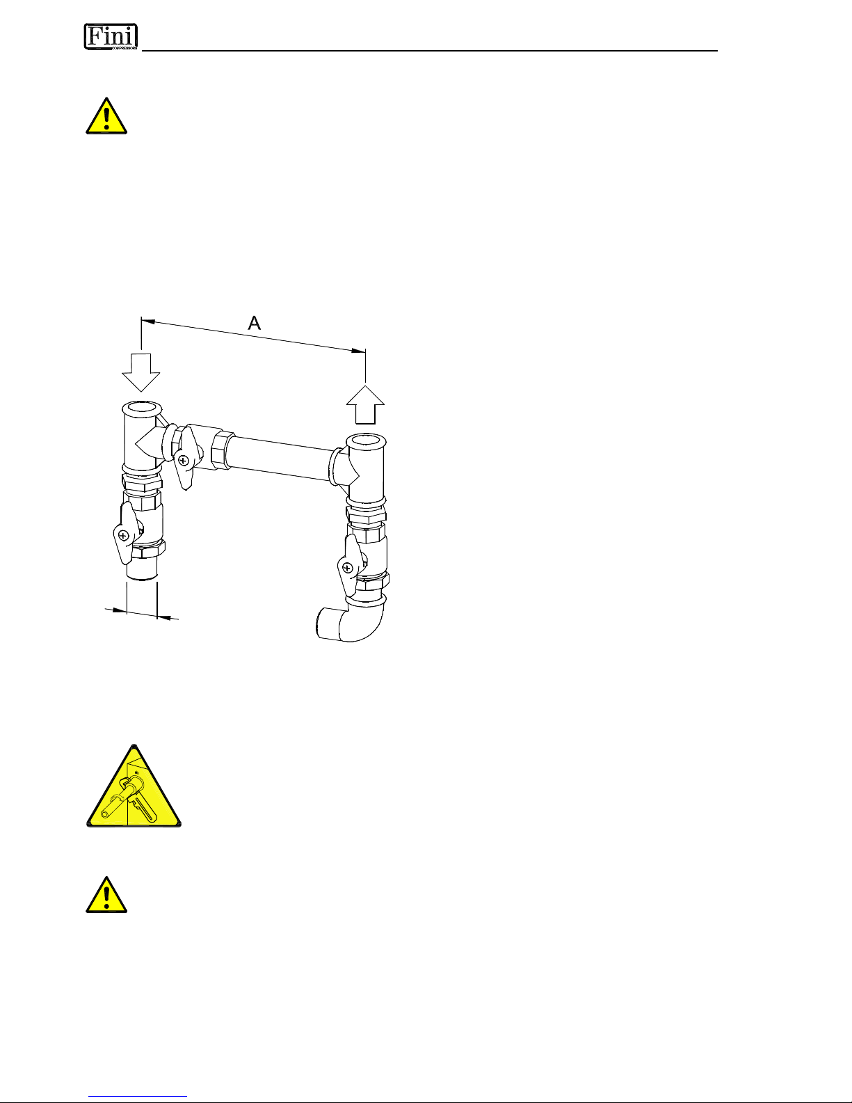
In order to facilitate the maintenance operations, we suggest installing a by-pass group, as shown in the
following illustration.
Ø
B
P
Y
0
0
0
1
In realising the dryer, particular measures have been taken in order to limit the vibration which could occur
during the operation.
Therefore we recommend to use connecting pipes able to insulate the dryer from possible vibrations
originating from the line (flexible hoses, vibration damping fittings, etc.).
CAUTION:
PIPING THE DRYER, INLET/OUTLET CONNECTIONS MUST BE SUPPORTED AS
SHOW IN THE DIAGRAM.
FAILING WILL RESULT IN DAMAGE
2.7 CONNECTION TO THE COOLING WATER NETWORK (Water-Cooled)
Operations to be performed by qualified personnel.
Never operate with plants under pressure.
The user is responsible to ensure that the dryer will never be operated with pressure exceeding
the nominal values.
Eventual over-pressure could be dangerous both for the operator and the machine.
The temperature and the amount of cooling water must comply with the limits indicated on the technical
characteristics chart.
The cross section of the connection pipes, preferably flexible, must be free from rust, chips and other
impurities, must be consistent with the flow-rate of the dryer.
Page 12

2.8 ELECTRICAL CONNECTIONS
The connection to the mains, to be carried out by qualified personnel, and the safety systems must
comply with local rules and laws.
Before connecting the unit to the electric power, verify that the voltage and the frequency available on the
mains correspond to the data reported on the data plate of the dryer. In terms of voltage, a ±5% tolerance is
allowed.
The dryers RD come with an electric box for the connection to the mains.
The mains socket must be provided with a mains magneto-thermal differential breaker (I∆n=0.03A),
adjusted on the basis of the consumption of the dryer (see the nominal values on the data plate of the dryer).
The cross section of the power supply cables must comply with the consumption of the dryer, while keeping
into account also the ambient temperature, the conditions of the mains installation, the length of the cables,
and the requirements enforced by the local Power Provider.
Connect to a properly grounded outlet. Improper connection of the equipment-grounding
conductor can result in risk of electric shock.
Do not use adapters on the plug receptacle - if it does not fit the outlet, have a proper outlet
installed by a qualified electrician.
2.9 CONDENSATE DRAIN
The condensate is discharge at the system pressure.
Drain line should be secured
Never point the condensate drain line towards anybody.
The dryer comes with a flexible plastic drain tube.
The condensate drain occurs through a solenoid valve protected with a mechanical strainer.
The condensate coming from the separator is previously filtered, then discharged.
The solenoid valve coil is operated by electronic instrument (dryer controller).
If an electronic drainer is installed, the intervention times are determined by the internal capacitive sensor
(see specific paragraph).
The drainers cannot be connected to pressurized systems.
Don’t dispose the condensate in the environment.
The condensate collected in the dryer contains oil particles released in the air by the compressor.
Dispose the condensate in compliance with the local rules.
We suggest to install a water-oil separator where to convey all the condensate drain coming from
compressors, dryers, tanks, filters, etc.
3.1 PRELIMINARY OPERATION
Verify that the operating parameters match with the nominal values stated on the data nameplate of
the dryer (voltage, frequency, air pressure, air temperature, ambient temperature, etc.).
This dryer has been thoroughly tested, packaged and inspected prior to shipment. Nevertheless, the unit
could be damaged during transportation, check the integrity of the dryer during initial start-up and monitor
operation during the first hours of operation
Qualified personnel must perform the initial start-up.
When installing and operating this equipment, comply with all National Electrical Code and any
applicable federal, state and local codes.
Who is operating the unit is responsible for the proper and safe operation of the dryer.
Never operate equipment with panels removed.
Page 13

3.2 FIRST START-UP
This procedure should be followed on initial start-up, after periods of extended shutdown or
following maintenance procedures.
Qualified personnel must perform the start-up.
Sequence of operations (refer to paragraph 5.1 Control Panel) :
DMC14 Electronic Instrument DMC20 Electronic Instrument
• Ensure that all the steps of the “Installation”
chapter have been observed.
• Ensure that the connection to the compressed air
system is correct and that the piping is suitably
fixed and supported.
• Ensure that the condensate drain pipe is properly
fastened and connected to a collection system or
container.
• Ensure that the by-pass system (if installed) is
closed and the dryer is isolated.
• Ensure that the manual valve of the condensate
drain circuit is open.
• Remove any packaging and other material which
could obstruct the area around the dryer.
• Activate the mains switch.
• Turn on the main switch - pos. 1 on the control
panel.
• Check that the mains detection light of the
ON/OFF button - pos. 4 of the control panel - is
ON.
• Wait at least two hours before starting the dryer
(compressor crankcase heater must heat the oil
of the compressor).
• Ensure the cooling water flow and temperature is
adequate (Water-Cooled).
• Switch ON the dryer button "I - ON" of the
ON/OFF switch - pos. 4 on the control panel.
• Ensure that DMC14 electronic instrument is ON.
• Ensure the consumption matches with the values
of the data plate.
• Check that the rotation direction of the fan
corresponds with the arrows on the
condenser (Air-Cooled).
• Allow the dryer temperature to stabilise at the
pre-set value.
• Slowly open the air inlet valve.
• Slowly open the air outlet valve.
• Slowly close the central by-pass valve of the
system (if installed).
• Check the piping for air leakage.
• Ensure the drain is regularly cycling - wait for its
first interventions.
• Ensure that all the steps of the “Installation”
chapter have been observed.
• Ensure that the connection to the compressed air
system is correct and that the piping is suitably
fixed and supported.
• Ensure that the condensate drain pipe is properly
fastened and connected to a collection system or
container.
• Ensure that the by-pass system (if installed) is
closed and the dryer is isolated.
• Ensure that the manual valve of the condensate
drain circuit is open.
• Remove any packaging and other material which
could obstruct the area around the dryer.
• Activate the mains switch.
• Turn on the main switch - pos. 1 on the control
panel.
• Check that "crankcase oil heater" and "Stand-by"
leds on DMC20 are ON.
• Wait at least two hours before starting the dryer
(compressor crankcase heater must heat the oil of
the compressor).
• Ensure the cooling water flow and temperature is
adequate (Water-Cooled).
• Switch ON the dryer keeping the “Dryer Start-up”
button on DMC20 pressed for at least 2 seconds.
• Check that “compressor ON” led on DMC20 is ON.
• Ensure the consumption matches with the values
of the data plate.
• Check that the rotation direction of the fan
corresponds with the arrows on the condenser
(Air-Cooled).
• Allow the dryer temperature to stabilise at the preset value.
• Slowly open the air inlet valve.
• Slowly open the air outlet valve.
• Slowly close the central by-pass valve of the
system (if installed).
• Check the piping for air leakage.
• Ensure the drain is regularly cycling - wait for its
first interventions.
Page 14
3.3 START-UP AND SHUT DOWN
Start-up (refer to paragraph 5.1 Control Panel) :
DMC14 Electronic Instrument DMC20 Electronic Instrument
• Check the condenser for cleanliness (AirCooled).
• Ensure the cooling water flow and temperature is
adequate (Water-Cooled).
• Check that the mains detection light of the
ON/OFF button - pos. 4 of the control panel - is
ON.
• Switch ON the dryer button "I - ON" of the
ON/OFF switch - pos. 4 on the control panel.
• Ensure that DMC14 electronic instrument is ON.
• Wait a few minutes; verify that the DewPoint
temperature displayed on electronic instrument
DMC14 is correct and that the condensate is
regularly drained.
• Switch on the air compressor.
• Check the condenser for cleanliness (Air-Cooled).
• Ensure the cooling water flow and temperature is
adequate (Water-Cooled).
• Check that "crankcase oil heater" and "Stand-by"
leds on DMC20 are ON.
• Switch ON the dryer keeping the “Dryer Start-up”
button on DMC20 pressed for at least 2 seconds.
• Check that “compressor ON” led on DMC20 is ON.
• Wait a few minutes; verify that the DewPoint
temperature displayed on electronic instrument
DMC20 is correct and that the condensate is
regularly drained.
• Switch on the air compressor.
Shut down (refer to paragraph 5.1 Control Panel) :
DMC14 Electronic Instrument DMC20 Electronic Instrument
• Check that the DewPoint temperature indicated
on the DMC14 is within range.
• Switch OFF the air compressor.
• After a few minutes, switch OFF the dryer
pressing the "O - OFF" button of the ON/OFF
switch - pos. 4 on the control panel.
• Check that the DewPoint temperature indicated on
the DMC20 is within range.
• Switch OFF the air compressor.
• After few minutes, switch OFF the dryer keeping
the “Dryer Stop” button on DMC20 pressed for at
least 2 seconds.
NOTE : A DewPoint within 0°C and +10°C displayed on the electronic controller is correct according
to the possible working conditions (flow-rate, temperature of the incoming air, ambient
temperature, etc.).
During the operation, the refrigerating compressor will run continuously. The dryer must remain on during
the full usage period of the compressed air, even if the air compressor works intermittently.
The number of starts must be no more than 6 per hour. The dryer must stop running for at
least 5 minutes before being started up again.
The user is responsible for compliance with these rules. Frequent starts may cause
irreparable damage.
Page 15

4.1 TECHNICAL SPECIFICATIONS ACT 185-810 /AC
810
81000
4860
2862
0.30
DN125 PN16
11.00
15500
8500
14.6
11000
17.9
700
620
62000
3720
2191
0.20
9.80
15500
6700
11.5
8900
15.0
580
480
48000
2880
1696
0.23
DN100 PN16
9.00
15500
6500
11.1
8600
14.6
< 80
530
410
41000
2460
1449
0.30
4.60
6500
5000
9.0
6500
11.7
302
350
35000
2100
1237
0.19
0.24
4.00
4.00
6500
4400
8.7
5700
11.2
277
250
25000
1500
883
0.23
2.60
5300
3500
6.3
5400
8.9
242
Air
-
Cooled
185
18500
1110
654
+3 equal to 0.73 g/Nm
3
of H
2
O
+25 (+45)
+1
+35 (+55)
7
14
0.18
DN80 PN16
R404A
2.50
5300
-
-
-
-
-
-
3/400-415/50
3350
5.6
4700
7.4
< 75
232
[l/min] [m
3
/h]
[scfm]
[°C] [°C] [°C] [°C]
[barg] [barg]
[bar]
[BSP
-
F]
[kg]
[m
3
/h]
[m
3
/h]
[m
3
/h]
[°C]
[barg]
[BSP
-
F]
[Ph/V/Hz]
[W]
[A]
[W]
[A]
[dbA]
[kg]
ACT MODEL
Air flow rate at nominal condition
1
Pressure DewPoint at nominal condition
1
Nom. ambient temperature. (max.) Min. ambient temperature Nomin
al inlet air temperature. (max.)
Nominal inlet air pressure Max. inlet air pressure
Air pressure drop
-
∆
p
Inlet
-
Outlet connections
Refrigerant type Refrigerant quantity
3
Cooling air flow
Cooling water flow at 15°C (out 30°C)
Cooling water flow at 30°C (out 40°C)
Control of cooling water flow Maximum water temperature
2
Maximum (min.) water pressure Cooli
ng water connections
Standard Power Supply
3
Nominal electric absorption
Max. electric absorption
Max. level noise at 1 m Weight
1
Th e no m in a l c o n d i t io n re f e rs to a n a m b i e nt t em p e r a t u r e of + 25 °C w i t h i n l et a ir a t 7 b a r g a n d + 3 5 °C. 2 Ot h e r t e mp e r a t u r e o n r e qu e s t . 3 Ch e c k t h e d at a sh o w n o n t h e i d en t i f i c at i o n p l a t e .
Page 16

4.2 TECHNICAL SPECIFICATIONS RD 185-810 /WC
810
81000
4860
2862
0.30
DN125 PN16
8.80
1.69
2.53
7800
13.4
10300
16.7
690
620
62000
3720
2191
0.20
4.70
1.27
1.90
6000
10.3
8200
13.8
570
480
48000
2880
1696
0.23
DN100 PN16
4.00
1.25
1.80
G 1”
5800
9.9
7900
13.4
520
410
41000
2460
1449
0.30
2.40
0.87
1.32
5800
9.9
7900
13.4
297
350
35000
2100
1237
0.24
1.80
0.75
1.13
3650
6.9
5000
9.5
227
250
25000
1500
883
0.23
1.45
0.62
1.94
3050
5.6
4600
8.1
237
Water
-
Cooled
ad acqua
185
18500
1110
654
+3 uguale a 0.73 g/Nm
3
di H
2
O
+25 (+45)
+1
+35 (+55)
7
14
0.18
DN80 PN16
R404A
1.35
-
0.54
0.82
Automatic valve
30
3 (10)
G 3/4"
3/400-415/50
2900
4.8
4200
6.6
< 75
227
[l/min] [m
3
/h]
[scfm]
[°C] [°C] [°C] [°C]
[barg] [barg]
[bar]
[BSP-F]
[kg]
[m
3
/h]
[m
3
/h]
[m
3
/h]
[°C]
[barg]
[BSP
-
F]
[Ph/V/Hz]
[W]
[A]
[W]
[A]
[dbA]
[kg]
RD
MODEL
Air flow
rate at nominal condition
1
Pressure DewPoint at nominal condition
1
Nom. ambient temperature. (max.) Min. ambient temperature Nominal inlet air temperature. (max.) Nominal inlet air pressure Max. inlet air pressure
Air pressure drop
-
∆
p
Inlet - Outlet connections
Refrigerant type Refrigerant quantity
3
Cooling air flow
Cooling water flow at 15°C (out 30°C)
Cooling water flow at 30°C (out 40°C)
Control of cooling water flow Maximum water temperature
2
Maximum (min.) water pressure Cooli
ng water connections
Standard Power Supply
3
Nominal electric absorption
Max. electric absorption
Max. level noise at 1 m Weight
1
Th e no m in a l c o n d i t io n re f e rs to a n a m b i e nt t em p e r a t u r e of + 25 °C w i t h i n l et a ir a t 7 b a r g a n d + 3 5 °C. 2 Ot h e r t e mp e r a t u r e o n r e qu e s t . 3 Ch e c k t h e d at a sh o w n o n t h e i d en t i f i c at i o n p l a t e .
Page 17
5.1 CONTROL PANEL
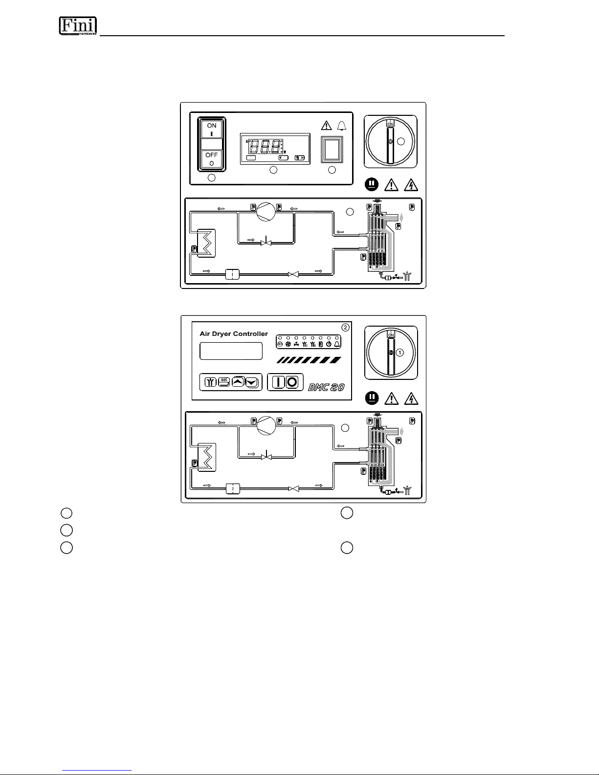
The control panel illustrated below is the only dryer-operator interface.
RD 185 - 810 - DMC14
K
2
set
DMC 14
°C
esc
°F
1
5
4
3
P
Q
S
0
0
0
9
RD 185 - 810 - DMC20
K
3
P
Q
S
0
0
1
0
1
Main switch
4
ON/OFF switch
2
Electronic control instrument (DMC14-DMC20)
with mains detecting light
3
Air and refrigerating gas flow diagram
5
Alarm light
5.2 OPERATION
Operating principal -
The dryer models described in this manual operate all on the same principal. The hot moisture
laden air enters an air to air heat exchanger. The air then goes through the evaporator, also known as the air to
refrigerant heat exchanger. The temperature of the air is reduced to approximately 2°C, causing water vapor to condense
to liquid. The liquid is continuously coalesced and collected in the separator for removal by the condensate drain. The
cool moisture free air then passes back through the air to air heat exchanger to be reheated to within 8 degrees of the
incoming air temperature as it exits the dryer.
Refrigerant circuit -
Refrigerant gas is cycled through the compressor and exits at high pressure to a condenser
where heat is removed causing the refrigerant to condense to a high-pressure liquid state. The liquid is forced through
a capillary tube where the resulting pressure drop allows the refrigerant to boil off at a predetermined temperature. Lowpressure liquid refrigerant enters the heat exchanger where heat from the incoming air is transferred causing the
refrigerant to boil; the resulting phase change produces a low pressure, low temperature gas. The low-pressure gas is
returned to the compressor, where it is re-compressed and begins the cycle again. During those periods when the
compressed air load is reduced the excess refrigerant is by-passed automatically back to the compressor via the Hot
Gas By-pass Valve circuit.
Page 18

5.3 FLOW DIAGRAM (Air-Cooled)
12.1
T6
15
EC
1413
16
17
1
12
1c
T1
1b
1a
P
B
3 54
P
11
10
7
6
T
S
9 M
8
P
VA
T3
T2
12.1
12.1
T5
12.1
T4
12.1
12.1
T7
25
5
V1PV2
P
2
480-810
D
G
F
0
0
1
1
5.4 FLOW DIAGRAM (Water-Cooled)
10
11
6
1
7
12
P
2
P
B
4
T1
A
1a
1b
1c
13
16
EC
15
14
T
S
3
17
18
19
20
D
G
F
0
0
0
2
1
Alu-Dry Module
11
Capillary tube
a - Air-to-air heat exchanger
12
T1 Temperature probe (DewPoint)
b - Air-to-refrigerant exchanger
Temp. Probes T2-T8 → DMC20 (if installed)
c - Condensate separator
13
Condensate drain service valve
2
Refrigerant Pressure Switches PB
14
Y-shaped condensate drain strainer
3
Safety thermo-switch Ts
15
Condensate drain solenoid valve
4
Refrigerant Pressure Switches PA
16
Coil for cond. drain solenoid valve
5
Refrigerant pressure-switch (fan) PV
17
EC = Electronic control instrument
PV1 - PV2 (RD 480-810)
18
Condenser (Water-Cooled)
6
Compressor
19
Condenser water regulating valve (water-Cooled)
7
Hot gas by-pass valve
20
Liquid receiver (water-cooled)
8
Condenser (Air-Cooled) …
9
Condenser fan
25
Compressor crankcase heater
10
Filter Drier
Compressed air flow direction
Refrigerating gas flow direction
Page 19

5.5 REFRIGERATING COMPRESSOR
The refrigerating compressor is the pump in the system, gas coming from the evaporator (low pressure
side) is compressed up to the condensation pressure (high pressure side). The compressors utilized are
manufactured by leading manufacturers and are designed for applications where high compression ratios
and wide temperature changes are present.
The hermetically sealed construction is perfectly gas tight, ensuring high-energy efficiency and long, useful
life. Dumping springs support the pumping unit in order to reduce the acoustic emission and the vibration
diffusion. The aspirated refrigerating gas, flowing through the coils before reaching the compression
cylinders cools the electric motor. The thermal protection protects the compressor from over heating and
over currents. The protection is automatically restored as soon as the nominal temperature conditions are
reached.
5.6 CONDENSER (Air-Cooled)
The condenser is the element in which the gas coming from the compressor is cooled down and condensed
becoming a liquid. Mechanically, it is formed by a copper tubing circuit (with the gas flowing inside)
immersed in an aluminium blades package.
The cooling operation occurs via a high efficiency axial ventilator which, in applying pressure on the air
contained within the dryer, forces it into the blades package.
It’s mandatory that the temperature of the ambient air will not exceed the nominal values. It’s important TO
KEEP THE UNIT FREE FROM DUST AND OTHER IMPURITIES.
5.7 CONDENSER (Water-Cooled)
The condenser is the element in which the gas coming from the compressor is cooled down and condensed
becoming a liquid. Basically it is a water/refrigerating gas exchanger where the cooling water lowers the
temperature of the refrigerating gas.
The temperature of the inlet water must not exceed the nominal values. It must also guarantee an adequate
flow and that the water entering the exchanger is free from dust and other corrosive substances.
5.8 CONDENSER WATER REGULATING VALVE (Water-Cooled)
The condenser water regulating valve is used to keep the condensing pressure/temperature constant when
the Water-Cooled is being used. Thanks to the capillary tube, the valve detects the pressure in the
condenser and consequently adjusts the water flow. When the dryer stops the valve automatically closes
the cooling water flow.
The condenser water regulating valve is an operating control device.
The closure of the water circuit from the pressure condenser water regulating valve cannot be used
as a safety closure during service operations on the system.
ADJUSTMENT
The condenser water regulating valve is adjusted during the testing phase to a pre-set value that
covers 90% of the applications. However, sometimes the extreme operating conditions of the dryer
may require a more accurate calibration.
During start-up, a qualified technician should check the condensing pressure/temperature and if
necessary adjust the valve by using the screws on the valve itself.
To increase the condensing temperature, turn the adjusting screws counter-clockwise; to lower it turn
the screws clock-wise. Adjust the valve in order to guarantee a condensing temperature of 42-45 °C.
Page 20

5.9 FILTER DRIER
Traces of humidity and slag which could accumulate inside the chilling plant, or smudge which could occur
after a long use of the dryer, could limit the lubrication of the compressor and clog the capillary tube. The
function of the Filter Drier, located before the capillary tubing, is to stop the impurities, so avoiding their
circulation within the system.
5.10 CAPILLARY TUBE
It consists of a piece of reduced cross section copper tubing located between the condenser and the
evaporator to form a throttling against the flow of the refrigerating fluid. This throttling creates a pressure
drop, which is a function of the temperature to be reached within the evaporator: the lower the capillary tube
outlet pressure, the lower the evaporation temperature. The length and the diameter of the capillary tubing
are accurately sized with the performance to be reached by the dryer; no maintenance/adjustment
operations are necessary.
5.11 ALU-DRY MODULE
The heat exchanger module houses the air-to-air, the air-to-refrigerant heat exchangers and the demister
type condensate separator. The counter flow of compressed air in the air-to-air heat exchanger ensures
maximum heat transfer. The generous cross section of flow channel within the heat exchanger module
leads to low velocities and reduced power requirements. The generous dimensions of the air-to-refrigerant
heat exchanger plus the counter flow gas flow allows full and complete evaporation of the refrigerant
(preventing liquid return to the compressor). The high efficiency condensate separator is located within the
heat exchanger module. No maintenance is required and the coalescing effect results in a high degree of
moisture separation.
5.12 HOT GAS BY-PASS VALVE
This valve injects part of the hot gas (taken from the discharge side of the compressor) in the pipe between
the evaporator and the suction side of the compressor, keeping the evaporation temperature/pressure
constant at approx. +2 °C. This injection prevents the formation of ice inside the dryer evaporator at every
load condition
RD 185-410
A
4 mm
5/32 in.
+
-
V
L
Y
0
0
0
1
ADJUSTMENT
The hot gas by-pass valve is adjusted during the manufacturing
testing phase. As a rule no adjustment is required; anyway if it is
necessary the operation must be carried out by an experienced
refrigeration engineer.
WARNING : the use of ¼” Schrader service valves must be
justified by a real malfunction of the refrigeration system.
Each time a pressure gauge is connected, a part of refrigerant
is exhausted.
Without compressed air flow through the dryer, rotate the adjusting
screw (position A on the drawing) until the following value is
reached:
Hot gas setting (R404A) : temperature 0.5 °C (+0.5 / -0 °K)
pressure 5.2 barg (+0.1 / -0 bar)
RD 480-810
A
8 mm
5/16 in.
-
+
V
L
Y
0
0
0
3
Page 21

5.13 REFRIGERANT PRESSURE SWITCHES PA – PB – PV
As operation safety and protection of the dryer a series of pressure switches are installed in the gas circuit.
PB :
Low-pressure controller device on the suction side (carter) of the compressor, is enabled only if the
pressure drops below the pre-set value. The values are automatically reset when the nominal
conditions are restored.
Calibrated pressure : R 404 A Stop 1.0 barg - Restart 5.0 barg
PA :
This high-pressure controller device, located on the pushing side on the compressor, is activated
when the pressure exceeds the pre-set value. It features a manual-resetting button mounted on the
controller itself.
Calibrated pressure : R 404 A Stop 32 barg - Manual reset
PV : RD80-360 Fan control pressure switch located on the pushing side on the compressor. It keeps the
condensation temperature/pressure constant within preset limits (Air-Cooled).
Calibrated pressure :
RD 185-410
R 404 A
Start 20 barg (45°C) - Stop 18 barg (40°C) - Tolerance ± 1 bar
PV1 : RD480-810 Fan control pressure switch located on the pushing side on the compressor. It keeps
the condensation temperature/pressure constant within preset limits (Air-Cooled) – Low Speed.
Calibrated pressure : R 404 A
Start 21 barg (47°C) - Stop 18 barg (41°C) - Tolerance ± 1 bar
PV2 : RD480-810 Fan control pressure switch located on the pushing side on the compressor. It keeps
the condensation temperature/pressure constant within preset limits (Air-Cooled) – High Speed.
Calibrated pressure : R 404 A
Start 23 barg (51°C) - Stop 20.5 barg (46°C) - Tolerance ± 1 bar
5.14 SAFETY THERMO-SWITCH TS
1
2
P
Q
S
0
0
0
5
To protect the operating safety and the integrity of the dryer, a thermoswitch (TS) is installed on the refrigerant gas circuit. The thermo-switch
sensor, in case of unusual discharge temperatures, stops the refrigerating
compressor before it is permanently damaged.
Manually reset the thermo-switch only after the nominal operating
conditions have been restored. Unscrew the relative cap (see pos.1 in the
figure) and press the reset button (see pos.2 in the figure).
TS setting : temperature 100 °C (+2 / -2 °K)
5.15 COMPRESSOR CRANKCASE HEATER
At low temperatures oil can more easily be mixed with the refrigerant gas. So, when the compressor starts,
oil can be drawn into the refrigeration circuit and liquid hammering could occur.
To prevent this, an electrical resistance heater is installed in the suction side of the compressor. When the
system is powered and the compressor is not running, this heater keeps the oil at the correct temperature.
This heater is controlled by a thermo-switch which prevents overheating the oil.
NOTE : The heater must be powered at least a couple of hours before the start up of the refrigeration
compressor.
Page 22

5.16 DMC14 ELECTRONIC INSTRUMENT (AIR DRYER CONTROLLER)
set
Button - access the set-up.
esc
Button - Exit programming / decrease value.
Button - condensate drain test / value increment.
LED - Dryer in allarm status.
●
°C
LED - Display the set temperature scale (°C).
●
°F
LED - Display the set temperature scale (°F).
DMC 14
°C
°F
escset
DISPLAY
P
Q
S
0
0
0
6
●
LED - condensate drain solenoid valve on.
Through the digital thermometer with an alphanumerical display, the DMC14 controller shows the DewPoint
detected by the probe in the evaporator.
The LED indicates any alarm conditions, that may occur when:
- DewPoint too high;
- DewPoint too low;
- the probe is damaged.
If the probe is damaged the instrument displays the message “PF” (Probe Failure), and the alarm goes off
immediately. In case of alarm for a very low DewPoint (ASL fixed parameter equal to -2°C) the signal is
delayed by a fixed time (AdL parameter) of 30 sec, whereas in case of alarm for a very high the threshold value
(ASH parameter) can be set by the user and delayed by an AdH value, which can also be programmed (the
instrument has default settings that are indicated below). As soon as the DewPoint falls back into the set
temperature range the alarm is disabled.
DMC14 allows also remote annunciation of the alarm condition of the dryer; this through a volt free contact on
terminals 8 & 9 - please also see electric drawings into the attachments (max 250V 1A, min 5VDC 10mA)
- with dryer off or in alarm conditions contact is open
-
with dryer on and correct operating DewPoint, contact is closed.
OPERATION - After dryer starting, the electronic controller displays current operating DewPoint : it shows
the measured temperature in Celsius degrees (● °C) (
●
°C) with a resolution of 0.5°C or in Fahrenheit (
●
°F) with a resolution of 1°F.
The condensate drain solenoid valve is activated for 2 seconds (Ton) - LED (
●
) on - each minute (ToF),
if standard setting.
To perform the manual test for the condensate drain, press the button.
SET-UP
To access the set-up, keep pressed simultaneously both
set
and button for at least 5 seconds. In
this way programming operation will be activated and the controller display shows the first parameter that
can be set (Ton). After that, by pressing
set
button the display shows the value set for that parameter. If
the value is correct press
set
button to conferm it and to give access on following parameters. To change
the value of selected parameter, must be used
esc
and button, respectively to decrease or increase
the value. All parameters that can be modified are indicated in following table:
Display Description Value range Set value Equal to
Ton Activation time of the condensate drain solenoid valve. 01 … 20 02 2 sec
ToF Pause time of the condensate drain solenoid valve. 01 … 20 01 1 min
ASH Alarm threshold for a high DewPoint . 0.0 … 20.0 15 15°C
AdH ASH alarm time before signal 00 … 20 20 20 min
SCL Temperature scale °C … °F °C °Celsius
Fixed parameters :
ASL (low DewPoint alarm) = -2°C AdL (signal delay) = 30 sec
It is possibile to exit from set-up conditon in any moment, by pressing simultaneously both
esc
and
button. If any operations are not made during 30 seconds, the controller exits automatically from
programming operation.
Page 23
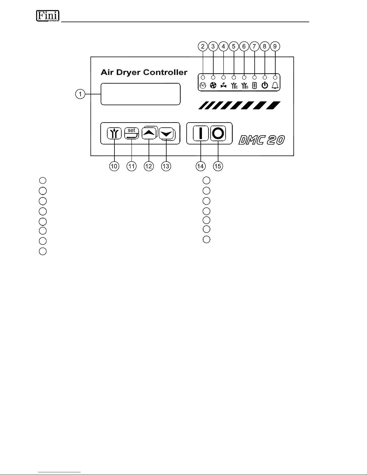
5.17 DMC20 ELECTRONIC INSTRUMENT (AIR DRYER CONTROLLER)
P
Q
S
0
0
1
1
1
Back-lighted LCD display
9
Led alarm ON
2
Led compressor ON
10
Condensate drain test button
3
Led condenser fan(s) ON
11
Set-up access button
4
Not Used
12
Incremental button
5
Not Used
13
Decrement button
6
Led condensate separator drain solenoid valve ON
14
Dryer start-up button
7
Led crankcase heater ON
15
Dryer stop button
8
Led dryer in Stand-by
The DMC20 controls all the operations, the alarms and the operational setting of the dryer. By means of a
32-character display it shows all the operating conditions. In case of abnormalities, a set of messages in the
selected language allows a fast detection of the fault and the relevant solution.
5.17.1 DISPLAY MESSAGES
When the main switch is turned ON, all the characters of the DMC20 display are activated for 2 seconds.
Afterwards, the software release appears, and finally the two lines of the display are ready for their normal
functions.
When the dryer is in stand-by condition, the display shows "Stand-by", and the "crankcase oil heater" and
"Stand-by" leds are ON. If the remote command is in use, the display shows "Stand-by Remote".
To switch ON the dryer, keep the button [14] "Dryer Start-up" pressed for at least 2 seconds. NOTE :
DMC20 has an internal timer that cannot allow to restart the compressor before 4 minutes after the
switch off. The upper line of the display will show the DewPoint. The following parameters can be selected
and displayed on the lower line:
Air →O
- temperature of the incoming air in °C
Air ←O
- temperature of the outgoing air °C
Compr.LP - suction temperature of the compressor (low pressure side) in °C
Compr.HP - discharge temperature of the compressor (high pressure side) in °C
Condens. - condensing temperature in °C
Ambient - ambient temperature in °C
Water →O
- inlet temperature of the cooling water (Water-Cooled) in °C
Working - operating time of the dryer in hours
The parameter to be displayed on the lower line is selected pressing the [12] or [13] keys.
In alarm condition, the list of the parameters to be displayed will include the DewPoint.
To switch OFF the dryer, keep the [15] button "Dryer Stop" pressed for at least 2 seconds.
Page 24

5.17.2 ALARMS
Any alarm condition is indicated by the flashing of the [9] led "Alarm" and the DMC20 activates a buzzer
tone in order to alert the operator. The operator can stop the buzzer by pressing any key. The cause of the
alarm will be displayed on the upper line of the LCD display.
Alarm Message
Cause
Intervention
Point
Intervention
Delay
Remarks
Protection Comp.
Thermal/electrical protection
of the compressor
- No delay The dryer is stopped
Protection Fan.
(Air-Cooled)
Thermal/electrical protection
of the fan
- No delay The dryer is stopped
STOP Compr.LP
PB Refrigerant low pressure
switch
R404A = 1.0 barg No delay The dryer is stopped
STOP Compr.HP
PA Refrigerant high
pressure switch
R404A = 32 barg No delay The dryer is stopped
Condens. HIGH
Condensation temperature
too high (probe T6)
50 - 70 °C
0.5-20
adjustable
The dryer is stopped
DewPoint LOW DewPoint low (probe T1) -10 - 0 °C
0.5-20
adjustable
The operator chooses
whether to stop dryer
DewPoint HIGH DewPoint high (probe T1) 10 - 20 °C
0.5-30 min
adjustable
The operator chooses
whether to stop dryer
Probe Fault One of the probes is faulty
- No delay The dryer does not stop
STORING ALARMS IN MEMORY
When the “Automatic Start-Up” and “Reset ! Autom.” functions are deactivated (customer selected
setting “no”), any alarm causing the dryer to stop and any anomaly with one or more probes (Probe Fault) is
stored in the memory of DMC20. To reset the alarm memory the dryer is to be switched OFF (keep the
button [15] "Dryer Stop" pressed for at least 2 seconds). The dryer is then to be switched ON again (keep
the button [14] "Dryer Start-up" pressed for at least 2 seconds); If the alarm is no longer in effect the dryer
will run correctly, otherwise the alarm message will appear again.
When the “Automatic Start-Up” and “Reset ! Autom.” functions are activated (customer selected setting
“yes”) any alarm which has caused the stop of the dryer and any anomaly with one or more probes (Probe
Fault) is automatically reset once nominal conditions return and the dryer will run again automatically.
Any alarm, which is not causing the stop of the dryer, is reset automatically when nominal working
conditions return.
5.17.3 SET-UP
The DMC20 is adjusted during the final test of the dryer. Where particular requirements concerning the
operation or the alarm management exist, the user can change the setting of the programmed parameters.
Set-up parameters are divided into two levels: anybody can access the level 1, while access to level 2 is
reserved to authorised personnel provided with the password.
To access to Set-up mode the [11] "Set-up access" button must be depressed for at least 2 seconds. Then
it will be possible to display the desired parameter using the [12] and [13] keys. To modify the displayed
parameter, use the [12] and [13] keys, while keeping the [11] key depressed.
During Set-up, the upper line of the display will display the selected parameter, while the lower line will show
the current value of the same parameter.
To exit Set-up mode, press simultaneously the [12] and [13] keys, or wait 20 seconds.
NOTE : The character “!” means “Alarm”
DESCRIPTION OF SET-UP PARAMETERS
LEVEL 1
• Pass Code? : The system asks for the password to access the level 2 of the programming parameters; If
the password is not modified or wrong, only the parameters of level 1 will be accessible; NOTE : The
password can be modified only when the dryer is in stand-by; therefore during operation, only the level 1
will be accessible.
• Language : It is possible to select the language for the alarm and dialogue messages.
Page 25

• DewPoint Set : Not Used.
• Diff. DewPoint : Not Used.
• E Drain Time : Not Used.
• E Drain Pause : Not Used.
• S Drain Time : Setting of the condensate drainage time of the solenoid valve located on the condensate
separator.
• S Drain Pause : Setting of the pause time between two successive condensate drain cycles of the valve
located on the condensate separator.
• Display Contrast. : Adjustment of the contrast of the LCD display, depending on the observation angle,
the illumination, the ambient temperature, etc.
LEVEL
2
• Min DewPoint : Not Used.
• Max DewPoint : Not Used.
• ! Low DewPoint : Setting of the threshold activating the alarm for the low DewPoint.
• Low DP Diff. ! : This is the differential temperature to deactivate the low DewPoint alarm.
• Low DP Delay !: Setting in minutes of the delay for the low DewPoint alarm; For example, setting the
"Low DewPoint !" value on -5, the "Low DP Diff.!” value on 6, and the "Low DP Delay !” value on 10, the
alarm is activated when the DewPoint remains below -5°C for at least 10 minutes and goes off as soon as
the DewPoint goes over +1ºC.
• Stop ! Low DP: Selecting “YES”, it is possible to enable the low DewPoint alarm to switch OFF the dryer;
otherwise a simple alarm signal is displayed.
• ! High DewPoint : Setting of the threshold activating the alarm for the high DewPoint.
• High DP Diff. ! : This is the differential temperature to deactivate the high DewPoint alarm.
• High DP Delay ! : Setting in minutes of the delay for the high DewPoint alarm; For example, setting the
"High DewPoint !" value on 15, the "High DP ! Diff.” value on -5, and the "High DP Delay !” value on 10,
the alarm is activated when the DewPoint remains over 15°C for at least 10 minutes a goes off as soon as
the DewPoint goes below +10ºC.
• Stop ! High DP : Selecting “YES”, it is possible to enable the high DewPoint alarm to switch OFF the
dryer; otherwise a simple alarm signal is displayed.
• Condensation ! : Setting of the activation threshold for the condensing temperature too high.
• Condens. Diff. ! : This is the differential temperature to deactivate the high condensing temperature alarm.
• Condens. Delay ! : Setting in minutes of the delay for the alarm when the condensing temperature is too
high; For example, setting the "Condensation !" value on 60, the "Condens.! Diff." value on -5, and the
"Condens.! Delay" value on 10, the alarm is activated when the condensing temperature remains over
+60°C for at least 10 minutes and goes off as soon as it falls, below +55ºC. NOTE : the condensing
temperature,” too high alarm” will switch OFF the dryer.
• Automatic Start-Up : At factory setting of “NO”, each time the dryer is powered ON it will always enter the
Stand-by condition; Selecting “YES”, the dryer will continue the function it was performing at the moment
of the power cut off.
SELECTING “YES” THE USER WILL BE RESPONSIBLE FOR THE INSTALLATION OF
PROPER PROTECTION FOR POSSIBLE SUDDEN POWER RESTORATION TO THE DRYER.
• Recovery After ! Autom. : Automatic alarms recovery; Selecting “NO”, in case of the activation of an
alarm that stopped the dryer, the operator will have to stop the alarm switching the dryer to stand-by
condition (pressing the [15] button for at least 2 seconds); If “YES” is selected, the dryer will revert to its
previous operational condition as soon as the nominal conditions will be restored.
SELECTING
“YES” THE USER WILL BE RESPONSIBLE FOR THE INSTALLATION OF
PROPER PROTECTION FOR POSSIBLE SUDDEN POWER RESTORATION TO THE DRYER.
•
Peripheral No : Assignment of a physical address for the DMC20, in case this is connected to a data
transmission network via a serial port.
Page 26

SET-UP PARAMETERS TABLE
Parameter Description
Adjustment
Range
Std
Value
Pass Code ? Password to access level 2
0 - 255
0
Language Selection of the language for dialogue and alarm messages
Italian - English
German - French
DewPoint Set Not Used
N.A.
-5 ºC
DewPoint Diff. Not Used
N.A.
0.2 ºK
E Drain Time Not Used
0 - 50 sec
3 sec
E Drain Pause Not Used
0.5 - 10 min 4.0 min
S Drain Time Discharge time of the condensate separator
0 - 50 sec
4 sec
S Drain Pause Pause between two condensate separator discharges
0.5 - 10 min 1.0 min
Display Contrast.
Adjustment of the Display contrast
0 - 100
50
Min DewPoint Not Used
N.A.
-10 ºC
Max DewPoint Not Used
N.A.
0 ºC
Low ! DewPoint
Temperature of interv. for the too low DewPoint alarm
-10.0 - 0.0 ºC -5 ºC
Low DP ! Diff. Differential temperature for the too low DewPoint alarm
1.0 - 10.0 ºK 6 ºK
Low DP ! Delay
Delay time for the too low DewPoint alarm
0.5 - 20 min 10 min
Low DP ! Stop STOP enabled in case the DewPoint of the dryer is too low
YES/NO
NO
High DewPoint !
Temperature of interv. for the too high DewPoint alarm
10.0 - 20.0 ºC 15 ºC
High DP ! Diff. Differential temperature for the too high DewPoint alarm
-1.0 - -10.0 ºK -5 ºK
High DP ! Delay
Delay time for the too high DewPoint alarm
0.5 - 30 min 20 min
High DP ! Stop
STOP enabled in case the DewPoint of the dryer is too high
YES/NO
NO
Condensation !
Temp. of intervention for the too high condensation
temperature alarm
50.0 - 70.0 ºC 60.0 ºC
Condens ! Diff.
Differential temp. for the too high condensation
temperature alarm
-1.0 - -10.0 ºK -5 ºK
Condens. ! Delay
Delay time for the too high condensation temp. alarm
0.5 - 20 min 10 min
Start at
Power Up
Machine enabled to restore its operation after a power
black out
YES/NO
NO
Recovery After !
Automatic alarms reset
YES/NO
NO
Peripheral No. Unit address for serial communication
01 - 255
01
5.17.4 REMOTE COMMAND
It is possible to remotely switch the dryer ON and OFF by means of a simple switch connected with two
wires to the DMC20 (see terminal 20 and 21 on the electric diagram). Closing the contact of the command
switch, on the display appears the message "Stand-by Remote", and no functions will be selectable on the
local panel; as soon as the contact is opened, the dryer returns to the previous condition (Stand-by if it was
in Stand-by condition, ON if it was ON).
I
F INSTALLED, THE REMOTE CONTROL HAS PRIORITY ON THE FRONTAL COMMANDS OF THE
DMC20.
THE
USER WILL BE RESPONSIBLE FOR THE INSTALLATION OF PROPER PROTECTIONS FOR POSSIBLE SUDDEN
POWER RESTORATION TO THE DRYER
.
L
E
V
E
L
1
L
E
V
E
L
2
Page 27

5.17.5 REMOTE ALARM SIGNAL
A voltage free contact is provided for remote signalling the sum of any alarm condition of the dryer.
5.17.6 ACCESS CODE
A serviceman’s code is required to access level 2.
The manufacturer accepts no responsibility for damages due to the alteration of the operating
parameters.
The password is specified in the last page of this manual.
The password must be kept by qualified personnel.
5.17.7 SERIAL COMMUNICATION
The DMC20 features an RS485 serial port (see terminal A and B on DMC20 back side) allowing the
connection to a network managed by a PC or PLC controller.
A maximum of 255 DMC20 units can be connected to the same network.
If a PC is used, the connection between the PC and the DMC20 network requires usage of an SBC485
interface adaptor (can be purchased as accessory - see spare parts list) to convert the RS232 (PC) signal
into an RS485 (DMS20) signal. The RS485 line is made of a two wire cable and can be up to max. 2000
meters long; for long distance (exceeding 100m), it is advisable to use a shielded twisted pair polyethylene
cable.
For good data transmission, it is imperative that at the cable end of the RS485 line a 120 ohm ¼ watt
resistor is placed, as shown in figure.
K
E S
set
RS 232
SBC 485
RS 48
5
A
B
120
K
E S
set
A
B
K
E S
set
A
B
CONNECTIONS COM # PC
25 pin RS232
SBC485
25 pin RS232
SBC485
9 pin RS485
DMC20
DATA connector
Shield - pin 1 n.c. A - pin 1 A Terminal
Tx - pin 2 pin 2 B - pin 2 B Terminal
Rx - pin 3 pin 3 Shield - pin 4 n.c.
RTS - pin 4 pin 4
CTS - pin 5 pin 5
GND - pin 7 pin 7
PROTOCOL
The data flow between PC and SBC485 is controlled by an RTS signal. The protocol used for
communication is a subset of MODICON MODBUS 1 (MB1); functions 03 and 06 only are supported. Data
are exchanged in ASCII mode with the following format:
Baudrate : 9600 Data bit : 7 Stop bit : 1 Parity : even
Page 28

DATABASE
Below is a list of the parameter description, type and address of data on DMC20 :
Data
Description
Type
Register
Address
DewPoint
DewPoint temperature - T1 probe
Signed Integer
0000 - R
Air →O
Temperature of the incoming air - T2 probe
Signed Integer
0001 - R
Air ←O
Temperature of the outgoing air - T3 probe
Signed Integer
0002 - R
Compr.LP
Suction temperature of the compressor (low pressure side) - T4 probe
Signed Integer
0003 - R
Compr.HP
Outlet temperature of the compressor (high pressure side) - T5 probe
Signed Integer
0004 - R
Condens.
Condensing temperature - T6 probe
Signed Integer
0005 - R
Water →O
Inlet temperature of the cooling water (Water-Cooled) - T8 probe
Signed Integer
0006 - R
Ambient
Ambient temperature - T7 probe
Signed Integer
0007 - R
Language 1)
Selection of the language for dialogue and alarm messages
Signed Integer
0200 - R/W
DewPoint Set Not Used
Signed Integer
0201 - R/W
Diff. DewPoint Not Used
Signed Integer
0202 - R/W
E Drain Time Not Used
Signed Integer
0203 - R/W
E Drain Pause Not Used
Signed Integer
0204 - R/W
S Drain Time Discharge time of the condensate separator
Signed Integer
0205 - R/W
S Drain Pause Pause between two condensate separator discharges
Signed Integer
0206 - R/W
Display Contrast.
Adjustment of the Display contrast
Signed Integer
0207 - R/W
Min DewPoint Not Used
Signed Integer
0208 - R/W
Max DewPoint Not Used
Signed Integer
0209 - R/W
Low DewPoint Temperature of interv. for the too low DewPoint alarm
Signed Integer
0210 - R/W
Low DP Diff.! Differential temperature for the too low DewPoint alarm
Signed Integer
0211 - R/W
Low DP Delay! Delay time for the too low DewPoint alarm
Signed Integer
0212 - R/W
High DewPoint ! Temperature of interv. for the too high DewPoint alarm
Signed Integer
0213 - R/W
High DP Diff.! Differential temperature for the too high DewPoint alarm
Signed Integer
0214 - R/W
High DP Delay! Delay time for the too high DewPoint alarm
Signed Integer
0215 - R/W
Condensation ! Temperature of intervention for the too high DewPoint alarm
Signed Integer
0216 - R/W
Condens.Diff.! Differential temperature for the too high DewPoint alarm
Signed Integer
0217 - R/W
Condens.Delay! Delay time for the too high DewPoint alarm
Signed Integer
0218 - R/W
Peripheral No Unit address for serial communication
Signed Integer
0219 - R/W
Working
Operating time of the dryer in hours
Signed Integer
0246 - R/W
Alarm STOP Presence of an alarm that has stopped the dryer
bit - 1=Yes 0100.0 - R
Alarm Status Presence of an alarm
bit - 1=Yes 0100.1 - R
Cond. Fan Switch
Status of the condenser fan control pressure switch
bit - 1=ON 0101.3 - R
Remote ON/OFF
Switch
Status of the Remote ON/OFF switch
bit - 0=Local
1=Remote
0101.6 - R
DewPoint LOW Low DewPoint alarm ON
bit - 1=Yes 0102.0 - R
DewPoint HIGH High DewPoint alarm ON
bit - 1=Yes 0102.1 - R
Condens. HIGH High Condensation temperature alarm ON
bit - 1=Yes 0102.2 - R
STOP Compr.LP
Cooler low pressure switch (PB) alarm ON
bit - 1=Yes 0102.4 - R
STOP Compr.HP
Cooler high pressure switch (PA) alarm ON
bit - 1=Yes 0102.5 - R
Protection Fan. Fan thermal/electrical protections alarm ON (Air-Cooled)
bit - 1=Yes 0102.6 - R
Protection Comp.
Compressor thermal/electrical protections alarm ON
bit - 1=Yes 0102.7 - R
Probe Fault
Probe faulty alarm ON
bit - 1=Yes 0102.8 - R
Stop ! Low DP STOP enabled in case the DewPoint of the dryer is too low
bit - 1=Yes 0220.0 - R/W
Stop ! High DP STOP enabled in case the DewPoint of the dryer is too high
bit - 1=Yes 0220.1 - R/W
Automatic
Start-up
Machine enabled to restore its operation after a power black out
bit - 1=Yes 0220.2 - R/W
Recovery After !
Autom.
Automatic alarms reset
bit - 1=Yes 0220.3 - R/W
ON/OFF DMC20
Status of DMC20 - ON or OFF (Stand-by)
bit-1=Stand-by
0220.15 - R/W
NOTE : 1) Language selection : 00=Italian - 01=English - 02=German - 03=French
R=Read - W=Write
Page 29
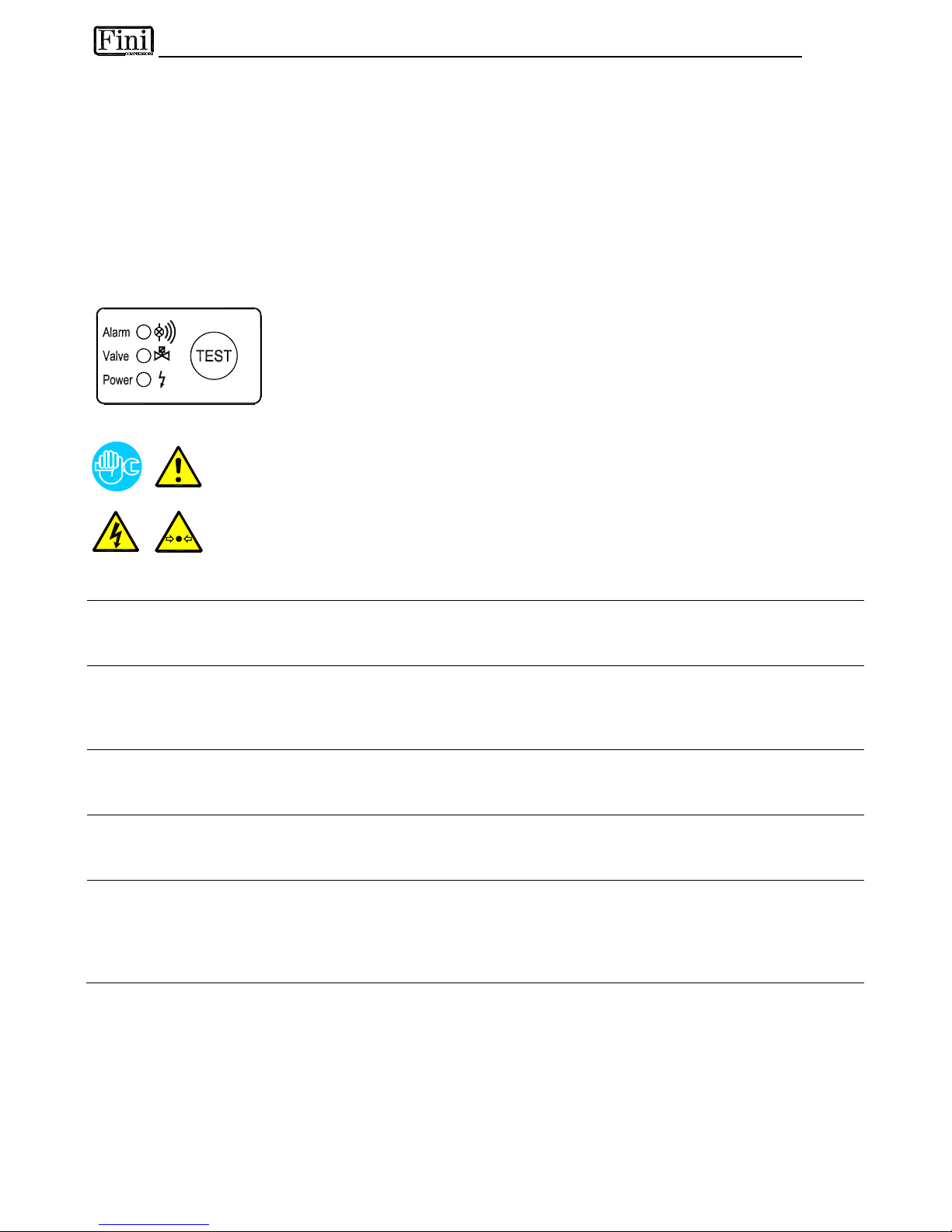
5.18 ELECTRONIC LEVEL DRAIN
Instead of the usual drain system (a solenoid valve controlled by means of electronic instrument); an
electronic level controlled drain can be installed as option. This drain consists of a condensate accumulator
where a capacitive sensor continuously checks the level of the liquid: as soon as the accumulator is filled,
the sensor passes a signal to the electronic control and a diaphragm solenoid valve will open to discharge
the condensate. For a complete condensate discharge the valve opening time will be adjusted exactly for
each single drain operation to avoid wasting air. No Y-shaped filter is installed and no adjusting is required.
A service valve is installed before the electronic drain in order to make check and maintenance operation
easy.
AT DRYER START-UP VERIFY THAT THIS VALVE IS OPEN.
CONTROL PANEL
The control panel here illustrated allows checking of drain working.
Power : LED ON - drain ready to work / supplied
Valve : LED ON - membrane solenoid valve open / discharging
Alarm : LED ON - drain in alarm condition
Test : button - discharge test (keep pushed for 2 seconds)
TROUBLESHOOTING
Only qualified personnel should perform troubleshooting and or maintenance operations.
Prior to performing any maintenance or service, be sure that:
• no part of the machine is powered and that it cannot be connected to the mains supply.
• no part of the machine is under pressure and that it cannot be connected to the compressed
air system.
•
Maintenance personnel have read and understand the safety and operation instructions in
this manual.
SYMPTOM POSSIBLE CAUSE - SUGGESTED ACTION
No led lighting up. Verify that the system is powered.
Verify the electric wiring (internal and/or external).
Check internal printed circuit board for possible damage.
Pressing of Test button,
but no condensate
discharge.
The service valve located before the drain is closed - open it.
The dryer is not under pressure - restore nominal condition.
Solenoid valve defective - replace the drain.
The internal printed circuit board is damaged - replace the drain.
Condensate discharge
only when Test button is
pressed.
The capacitive sensor is too dirty - open the drain and clean the sensor
plastic tube.
Drain keeps blowing off
air.
The diaphragm valve is dirty - open the drain and clean it.
The capacitive sensor is too dirty - open the drain and clean the sensor
plastic tube.
Drain in alarm condition. The capacitive sensor is too dirty - open the drain and clean the sensor
plastic tube.
The service valve located before the drain is closed - open it.
The dryer is not under pressure - restore nominal condition.
Solenoid valve defective - replace the drain.
NOTE : When the drain is in alarm condition, the diaphragm solenoid valve will open 7.5 sec every 4 min.
Page 30

6.1 CONTROLS AND MAINTENANCE SCHEDULE
Only qualified personnel should perform troubleshooting and or maintenance operations.
Prior to performing any maintenance or service, be sure that:
• no part of the machine is powered and that it cannot be connected to the mains supply.
• no part of the machine is under pressure and that it cannot be connected to the
compressed air system.
• Maintenance personnel have read and understand the safety and operation instructions
in this manual.
Before attempting any maintenance operation on the dryer, shut it down and wait at least 30
minutes.
Some components can reach high temperature during operation. Avoid contact until system or
component has dissipated heat.
DAILY
• Verify that the DewPoint displayed on the electronic instrument is correct.
• Check the proper operation of the condensate drain systems.
• Verify the condenser for cleanliness.
EVERY 200 HOURS OR MONTHLY
• With an air jet (max. 2 bar / 30 psig) blowing from inside towards outside
clean the condenser; repeat this operation blowing in the opposite way; be
careful not to damage the aluminium fins of the cooling package.
• At the end, check the operation of the machine.
EVERY 1000 HOURS OR YEARLY
• Verify for tightness all the screws of the electric system and that all the “Faston” type
connections are in their proper position, inspect unit for broken, cracked or bare wires.
• Inspect refrigerating circuit for signs of oil and refrigerant leakage.
• Measure and record amperage. Verify that readings are within acceptable parameters as listed
in specification table.
• Inspect condensate drain flexible hoses, and replace if necessary.
• At the end, check the operation of the machine.
Page 31

6.2 TROUBLESHOOTING
Only qualified personnel should perform troubleshooting and or maintenance operations.
Prior to performing any maintenance or service, be sure that:
• no part of the machine is powered and that it cannot be connected to the mains supply.
• no part of the machine is under pressure and that it cannot be connected to the compressed air
system.
• Maintenance personnel have read and understand the safety and operation instructions in this
manual.
Before attempting any maintenance operation on the dryer, shut it down and wait at least 30
minutes.
Some components can reach high temperature during operation. Avoid contact until system or
component has dissipated heat.
SYMPTOM POSSIBLE CAUSE - SUGGESTED ACTION
The dryer doesn't
start.
Verify that the system is powered.
Verify the electric wiring.
Intervention of the electric protection (see Q3 on the electric diagram) of the auxiliary circuit
- restore it and check the proper operation of the dryer.
RD480-810/AC- The back panel of the dryer is open (SD door interlock safety-switch has
been activated) - make sure the back panel is correctly closed and the SD switch restored.
DMC14- The “alarm” led is ON - see specific point.
DMC20- The “alarm in progress” led is ON - see specific point.
The compressor
doesn’t work.
Activation of the compressor internal thermal protection - wait for 30 minutes, then retry.
Verify the electric wiring.
Where installed- Replace the internal thermal protection
The high pressure switch PA has been activated - see specific point.
The low pressure switch PB has been activated - see specific point.
The safety thermo-switch TS has been activated - see specific point.
DMC14- The “alarm” led is ON - see specific point.
DMC20- Internal delay device – wait at least 4 min from last shut-off.
DMC20- The “alarm in progress” led is ON - see specific point.
If the compressor still doesn’t work, replace it.
The fan of the
condenser doesn’t
work (Air-Cooled).
Verify the electric wiring.
RD 185-410- PV pressure switch is faulty - contact a refrigeration engineer.
RD 480-810- PV1-PV2 pressure switches are faulty - contact a refrigeration engineer.
The fan power contactor (see V on the electric diagram) is faulty - replace it.
DMC14- The “alarm” led is ON - see specific point.
DMC20- The “alarm in progress” led is ON - see specific point.
If the fan still doesn't work, replace it.
DewPoint too high.
The dryer doesn't start - see specific point.
The T1 DewPoint probe doesn’t correctly detect the temperature - ensure the sensor is
pushed into the bottom of copper tube immersion well.
The refrigerating compressor doesn’t work - see specific point.
The ambient temperature is too high or the room aeration is insufficient - provide proper
ventilation (Air-Cooled).
The inlet air is too hot - restore the nominal conditions.
The inlet air pressure is too low - restore the nominal conditions.
The inlet air flow rate is higher than the rate of the dryer - reduce the flow rate - restore the
normal conditions.
The condenser is dirty - clean it (Air-Cooled).
The condenser fan doesn’t work - see specific point (Air-Cooled).
The cooling water is too hot - restore the nominal condition (Water-Cooled).
The cooling water flow is insufficient - restore the nominal condition (Water-Cooled).
The dryer doesn’t drain the condensate - see specific point.
The hot gas by-pass valve is out of setting - contact a refrigeration engineer to restore the
nominal setting.
There is a leak in the refrigerating fluid circuit - contact a refrigeration engineer.
Page 32
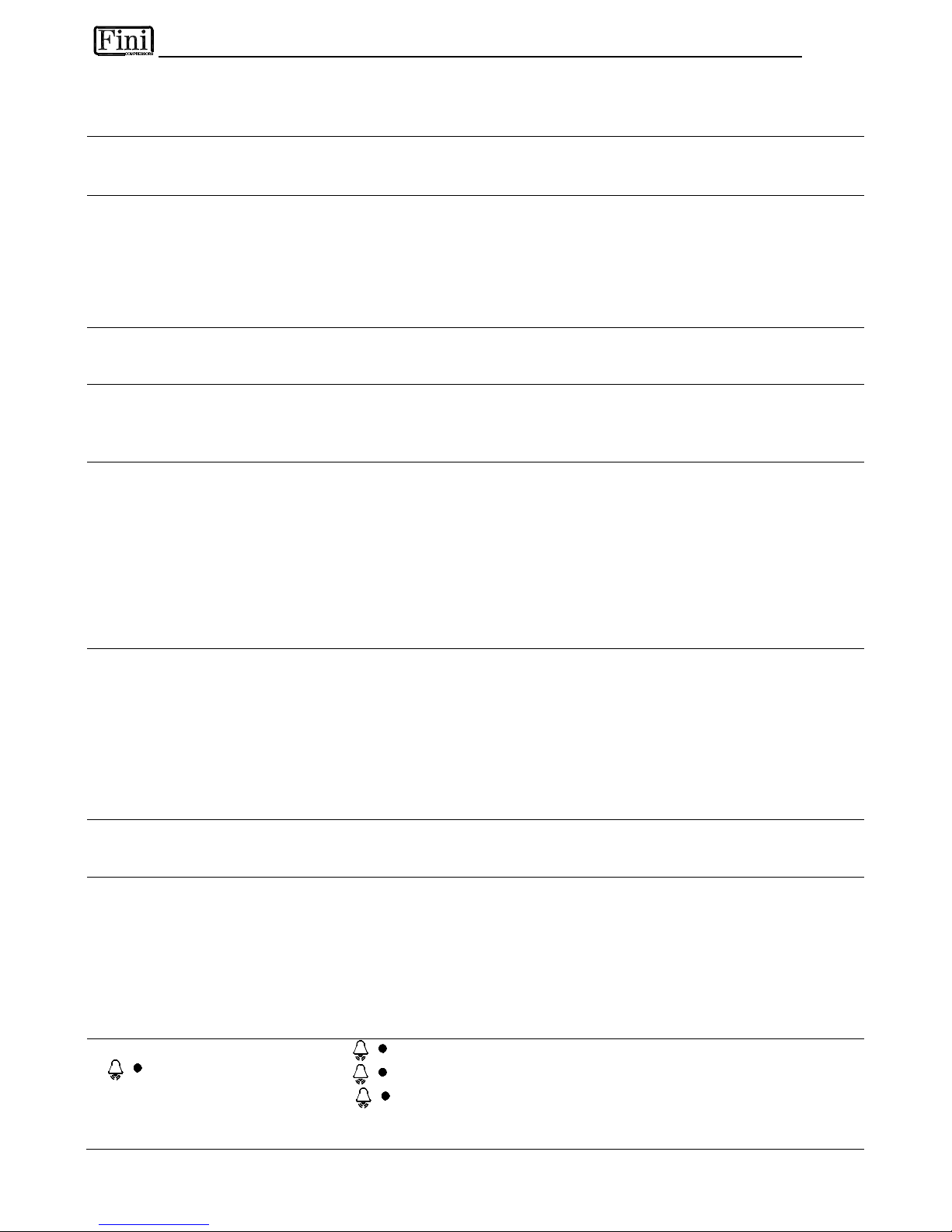
DewPoint too low.
The fan is always ON - PV pressure switch is faulty - replace it (Air-Cooled).
The hot gas by-pass valve is out of setting - contact a refrigeration engineer to restore the
nominal setting.
Excessive pressure
drop within the dryer.
The dryer doesn’t drain the condensate - see specific point.
The DewPoint is too low - the condensate is frost and blocks the air - see specific point.
Check for throttling the flexible connection hoses.
The dryer doesn’t
drain the condensate.
The condensate drain service valve is closed - open it.
The condensate drain strainer is clogged - remove and clean it.
The drain solenoid valve is jammed - remove and clean it.
Verify the electric wiring.
The coil of the condensate drain solenoid valve burned out - replace it.
The DewPoint is too low - the condensate is frozen - see specific point.
DMC20- Drain time on DMC20 is set at zero seconds. - see DMC20 “Set-Up” section.
The dryer
continuously drains
condensate.
The drain solenoid valve is jammed - remove and clean it.
Try to remove the electric connector on the solenoid valve - if drain stops verify the electric
wiring or the electronic instrument is faulty - replace it.
Water within the line.
The dryer doesn't start - see specific point.
Where installed - Untreated air flows through the by-pass unit - close the by-pass.
The dryer doesn’t drain the condensate - see specific point.
DewPoint too high - see specific point.
The safety thermo-
switch TS tripped.
Check which of the following has caused the activation :
1. Excessive thermal load – restore the standard operating conditions.
2. The inlet air is too hot - restore the nominal conditions.
3. The ambient temperature is too high or the room aeration is insufficient - provide proper
ventilation.
4. The condenser unit is dirty - clean it.
5. The fan doesn’t work - see specific point.
6. There is a leak in the refrigerating fluid circuit - contact a refrigeration engineer.
Reset the thermo-switch by pressing the button on the thermo-switch itself – verify the
correct operation of the dryer.
The TS thermo-switch is faulty - replace it.
The PA high-pressure
switch has been
activated.
Check which of the following has caused the activation :
1. The ambient temperature is too high or the room aeration is insufficient - provide proper
ventilation (Air-Cooled).
2. The condenser is dirty - clean it (Air-Cooled).
3. The condenser fan doesn’t work - see specific point (Air-Cooled).
4. The cooling water is too hot - restore the nominal condition (Water-Cooled).
5. The cooling water flow is insufficient - restore the nominal condition (Water-Cooled).
Reset the pressure-switch pressing the button on the controller itself - verify the dryer for
correct operation.
The PA pressure switch is faulty - contact a refrigeration engineer to replace it.
The PB low-pressure
switch has been
activated.
There is a leak in the refrigerating fluid circuit - contact a refrigeration engineer.
The pressure switch restores automatically when normal conditions are restored - check the
proper operation of the dryer.
DMC14- The “alarm”
led is ON.
The PA high-pressure switch is activated - see specific point.
The PB low-pressure switch is activated - see specific point.
The electric protection (see Q1 on the electric diagram) of the compressor is activated restore it and retry.
The electric protection (see Q2 on the electric diagram) of the fan(s) is activated - restore it
and retry (air cooled).
The thermal protection (see TV on the electric diagram) inside the fan is activated - wait 30
minutes and retry.
The safety thermo-switch TS has been activated - see specific point.
DMC14- The LED
of the
instrument is on or
flashes to indicate
alarm situations.
The LED flashes because the DewPoint is too high – see specific point.
The LED flashes because the DewPoint is too low - see specific point.
The LED flashes because the probe is faulty or interrupted, the instrument displays
the message “PF” (Probe Failure) – replace the probe.
Page 33

DMC20- The “alarm in
progress” led is on.
One of the following appears on the upper line of the DMC20 display :
1. "Protection Comp." : The electric protection (see Q1 on the electric diagram) of the compressor is
activated - restore it and retry.
2. "Protection Comp." : The safety thermo-switch TS has been activated - see specific point.
3. "Protection Fan": (Air-Cooled) : Intervention of the electric protection (see Q2 on the electric
diagram) of the fan - restore it and check the proper operation of the dryer
4. "Protection Fan": (Air-Cooled) : Intervention of the thermal protection (see TV on the electric
diagram) inside the fan - wait 30 minutes and retry.
5. “STOP Compr. LP” : The PB low pressure-switch is activated - see specific point.
6. “STOP Compr. HP” : The PA low pressure-switch is activated - see specific point.
7. “Condens. HIGH” : condensing temperature is too high - see specific point.
8. “LOW DewPoint” : The DewPoint is too low - see specific point.
9. “HIGH DewPoint” : The DewPoint is too high - see specific point.
10.“Probe Fault” : one of the probes is faulty - see specific point.
DMC20- The
condensing
temperature is too
high.
Check which of the following has caused the alarm :
1. The ambient temperature is too high or the room aeration is insufficient - provide proper
ventilation (Air-Cooled).
2. The condenser is dirty - clean it (Air-Cooled).
3. The condenser fan doesn’t work - see specific point (Air-Cooled).
4. The cooling water is too hot - restore the nominal condition (Water-Cooled).
5. The cooling water flow is insufficient - restore the nominal condition (Water-Cooled).
DMC20- DMC20
display “Probe Fault”
message.
One of the temperature probes is faulty - display in sequence all the temperatures - the
parameter indicated with “?” corresponds to faulty probe.
Verify that the probe-extension connector of faulty probe is correctly inserted in DMC20.
Check the probe-extension connection between DMC20 and terminal board.
Check electric connection between probe and terminal board.
If the fault persists, replace probe and/or probe-extension.
NOTE: If any probe is faulty the dryer will run correctly even if there is an alarm condition.
Page 34

6.3 MAINTENANCE OPERATION ON THE REFRIGERATION CIRCUIT
Maintenance and service on refrigeration systems must be carried out only by certified
refrigeration engineers only, according to local rules.
All the refrigerant of the system must be recovered for its recycling, reclamation or destruction.
DO NOT DISPOSE THE REFRIGERANT FLUID IN THE ENVIROMENT.
This dryer comes ready to operate and filled with R134a or R404A type refrigerant fluid.
In case of refrigerant leak contact a certified refrigeration engineers. Room is to be aired before
any intervention.
If is required to re-fill the refrigeration circuit, contact a certified refrigeration engineers.
Refer to the dryer nameplate for refrigerant type and quantity.
Characteristics of refrigerants used:
Refrigerant
Chemical formula TLV GWP
R134a - HFC CH2FCF3 1000 ppm 1300
R404A - HFC CH2FCF3/C2HF5/C2H3F3 1000 ppm 3784
6.4 DISMANTLING OF THE DRYER
If the dryer is to be dismantled, it has to be split into homogeneous groups of materials.
Parte
Materiale
Refrigerant fluid R404A, R134a, Oil
Canopy and Supports Carbon steel, Epoxy paint
Refrigerating compressor Steel, Copper, Aluminium, Oil
Alu-Dry Module Aluminium
Condenser Unit Aluminium, Copper, Carbon steel
Pipe Copper
Fan Aluminium, Copper, Steel
Valve Brass, Steel
Electronic Level Drain (optional) PVC, Aluminium, Steel
Insulation Material Synthetic rubber without CFC, Polystyrene, Polyurethane
Electric cable Copper, PVC
Electric Parts PVC, Copper, Brass
We recommend to comply with the safety rules in force for the disposal of each type of material.
The chilling fluid contains droplets of lubrication oil released by the refrigerating compressor.
Do not dispose this fluid in the environment. Is has to be discharged from the dryer with a suitable
device and then delivered to a collection centre where it will be processed to make it reusable.
Page 35
7.1 DRYERS DIMENSIONS
7.1.1 RD 185-350 /AC Dryers Dimensions
7.1.2 RD 410/AC Dryers Dimensions
7.1.3 RD 480-620 /AC Dryers Dimensions
7.1.4 RD 810/AC Dryers Dimensions
7.1.5 RD 185-350 /WC Dryers Dimensions
7.1.6 RD 410 /WC Dryers Dimensions
7.1.7 RD 480-620 /WC Dryers Dimensions
7.1.8 RD 810 /WC Dryers Dimensions
7.2 EXPLODED VIEW
7.2.1 Exploded view of Dryers RD 185-410
7.2.2 Exploded view of Dryers RD 480-810
Exploded view table of components
1
Alu-Dry Module
20
Liquid accumulator (water-cooled)
1.1 Insulation Material
21
Electronic level drain
2
Refrigerant pressure-switch PB
22
Main switch
3
Safety thermo-switch Ts
23
HP Refrigerant gauge (high-pressure)
4
Refrigerant pressure-switch PA
24
LP Refrigerant gauge (low-pressure)
5
Refrigerant Fan pressure-switch PV
25
Compressor crankcase heater
PV1 - PV2 (RD 480-810)
…
6
Compressor
51
Front panel
7
Hot gas by-pass valve
52
Back panel
8
Condenser (Air-Cooled)
53
Right lateral panel
9
Condenser fan
54
Left lateral panel
10
Filter Drier
55
Cover
11
Capillary tube
56
Base plate
12
T1 Temperature probe (DewPoint)
57
Upper plate
12.1 Temp. Probes T2-T8 → DMC20 (if installed)
58
Support beam
13
Condensate drain service valve
59
Support bracket
14
Y-shaped condensate drain strainer
60
Control panel
15
Condensate drain solenoid valve
61
Electric connector
16
Coil for cond. drain solenoid valve
62
Electric box
17
Air Dryer Controller
63
SD Door interlock safety-switch
18
Condenser (Water-Cooled)
64
Internal panel
19
Condenser water regulating valve (Water-Cooled)
Page 36

7.3 ELECTRICAL DIAGRAM
7.3.1
Electrical Diagram of Dryers RD 185-410 - Electronic Instrument DMC14 - POWER
7.3.2
Electrical Diagram of Dryers RD 185-410 - Electronic Instrument DMC14 - AUXILIARY
7.3.3
Electrical Diagram of Dryers RD 185-410 - Electronic Instrument DMC14 - CONNECTIONS
7.3.4
Electrical Diagram of Dryers RD 185-410 - Electronic Instrument DMC20 - POWER
7.3.5
Electrical Diagram of Dryers RD 185-410 - Electronic Instrument DMC20 - AUXILIARY
7.3.6
Electrical Diagram of Dryers RD 185-410 - Electronic Instrument DMC20 - CONNECTIONS
7.3.7
Electrical Diagram of Dryers RD 480-810 - Electronic Instrument DMC14 - POWER
7.3.8
Electrical Diagram of Dryers RD 480-810 - Electronic Instrument DMC14 - AUXILIARY
7.3.9
Electrical Diagram of Dryers RD 480-810 - Electronic Instrument DMC14 - CONNECTIONS
7.3.10
Electrical Diagram of Dryers RD 480-810 - Electronic Instrument DMC20 - POWER
7.3.11
Electrical Diagram of Dryers RD 480-810 - Electronic Instrument DMC20 - AUXILIARY
7.3.12
Electrical Diagram of Dryers RD 480-810 - Electronic Instrument DMC20 - CONNECTIONS
Electrical Diagram table of components
IG
: Main switch
K
: Refrigerating compressor
KT
: Compressor thermal protection
V
:
Condenser fan
TV
: Fan thermal protection
DMC14
: DMC14 Electronic Instrument - Air Dryer Controller
DMC20
:
DMC20 Display Module - Air Dryer Controller
DMC20RI
:
DMC20 Power Module - Air Dryer Controller
PR
:
Temperature probe (DewPoint)
PV
:
Pressure switch - Fan control
PV1 - PV2
:
Pressure switch - Fan control (RD 480-810)
PA
: Pressure switch - Compressor discharge side - (HIGH-pressure)
PB
:
Pressure switch - Compressor suction side (LOW pressure)
TS
:
Safety thermo-switch
BOX
: Electric box
EVD
:
Condensate drain solenoid valve
ELD
:
Electronic level drain
SEZ
:
Main switch with door block
P
:
Start-Stop button - Power on light
X
:
Alarm on light
R
:
Compressor crankcase heater
SD
:
Door interlock safety-switch
CP
:
Control panel
BN = BROWN
BU = BLUE
BK = BLACK
YG = YELLOW/GREEN
Page 37

7.1.3 RD 480-620 /AC
Page 38

40069 Zola Predosa (BO) - ITALY
7.1.4 RD 810 /AC
7.1.5 RD 185-350 /WC
7.1.6 RD 410 /WC
Page 39

Page 40

Page 41

Page 42

40069 Zola Predosa (BO) - ITALY
7.3.1 RD 185-410 - DMC14
S
E
Z
0
1
3
C
O
M
P
R
E
S
S
O
R
U
W
M
V
[
2
-
2
]
K
[
2
-
6
]
2
1
6
4
3
5
V
[
2
-
7
]
[
2
-
3
]
Q
1
Q
2
m
i
n
4
G
2
.
5
S
U
P
P
L
Y
U
n
l
e
s
s
s
p
e
c
i
f
i
e
d
1
x
1
r
d
A
T
F
Q
3
4
A
R
[
2
-
6
]
K
1
2
1
1
A
5
0
-
6
0
H
z
B
F
A
N
3
T
V
M
U
V
W
Page 43

40069 Zola Predosa (BO) - ITALY
7.3.2 RD 185-410 - DMC14
O
N
C
P
A
[
2
-
9
]
A
1
3
1
3
5
1
1
6
[
1
-
3
]
141
2
[
2
-
1
]
[
1
-
8
]
2
4
[
1
-
3
]
[
1
-
3
]
K
A
2
A
1
A
[
2
-
9
]
0
5
9
2
2
2
1
24126
5
1
1
1
3
[
1
-
4
]
N
.
U
.
[
1
-
4
]
[
1
-
4
]
A
1
A
2
V
P
N
X
L
P
V
O
N
C
P
1
W
h
X
2
X
1
B
P
1
3
K
1
3
1
4
[
2
-
1
]
1
4
R
d
4
1
2
[
2
-
1
]
[
2
-
7
]
4
1
8
5
129
1
3
1
4
A
P
[
1
-
5
]
Q
2
1
3
1
4
P
B
P
P
A
[
1
-
3
]
Q
1
1
4
1
3
T
V
T
S
P
T
1
POWER
2
D
E
W
-
P
O
I
N
T
A
L
A
R
M
m
a
x
2
3
0
V
1
(
1
)
A
4
5
8
9
DEW-POI
N
T PROBE
1
1
1
2
D
M
C
1
4
A
i
r
D
r
y
e
r
C
o
n
t
r
o
l
l
e
r
3
O
N
C
P
Page 44

40069 Zola Predosa (BO) - ITALY
7.3.3 RD 185-410 - DMC14
T1
T1
11
12
10
9
7
6
5
4
3
2
1
T
E
R
M
I
N
A
L
8
P
V
MOUNTING PLATE
R
red
UKK 5
T
E
R
M
I
N
A
L
14
12
W
I
R
E
15
12
26
23
22
T
Y
P
E
white
32
12
14
Q3
5
-
6
1
-
2
3
-
4
1
1
-
1
2
7
-
8
9
-
1
0
Q1 Q2
S
E
Z
T
1
TF
K V A
T
V
TS
P
A
P
B
Page 45

40069 Zola Predosa (BO) - ITALY
7.3.4 RD 185-410 - DMC20
S
E
Z
0
1
3
C
O
M
P
R
E
S
S
O
R
U
W
M
V
[
2
-
2
]
K
[
2
-
6
]
2
1
6
4
3
5
V
[
2
-
7
]
[
2
-
3
]
Q
1
Q
2
m
i
n
4
G
2
.
5
S
U
P
P
L
Y
U
n
l
e
s
s
s
p
e
c
i
f
i
e
d
1
x
1
r
d
A
T
F
Q
3
6
A
R
[
2
-
6
]
K
1
2
1
1
B
A
5
0
-
6
0
H
z
F
A
N
3
T
V
M
U
V
W
Page 46

40069 Zola Predosa (BO) - ITALY
7.3.5 RD 185-410 - DMC20
[
1
-
4
]
N
.
U
.
[
1
-
4
]
[
1
-
4
]
P
V
P
Q
1
A
[
1
-
3
]
1
C
T
1
4
3
2
T
2
T
3
T
4
[
1
-
8
]
1
1
1
2
1
1
1
2
O
P
T
I
O
N
A
L
N
L
Q
2
1
4
[
1
-
5
]
1
4
ON/OF
F
REMOT
E
B
T
7
6
5
1
3
1
3
T
5
T
6
7
T
8
K
V
5
6
1
3
2
4
[
1
-
3
]
[
1
-
3
]
[
1
-
3
]
A
2
513
624
A
2
A
1
A
1
3
1
1
3
1
2
K
1
1
B
D
M
C
2
0
R
I
1
4
1
5
E
6
5
1
6
S
7
T
V
T
S
P
P
P
B
P
P
A
Page 47

40069 Zola Predosa (BO) - ITALY
7.3.6 RD 185-410 - DMC20
17
15
11
10
8
9
P
V
MOUNTING PLATE
20
20
25
41
14
16 40
31
18 42
29
20
redT6
T2
T1
T2
T1
T3
T3
T4
T4
T5
T5
white
white
white
white
white
red
red
red
red
red
T7
T6
T7
T8
T8
white
white
white
red
red
T
6
Q1
1
3
-
1
4
1
1
-
1
2
7
-
8
9
-
1
0
1
-
2
3
-
4
5
-
6
1
5
-
1
6
T
2
T
1
T4T
3
T
5
DMC20RI
T8T
7
Q3
TF
K V
Q2
S
E
Z
1
7
-
1
8
12
16
12
13
T
V
T
E
R
M
I
N
A
L
R
3
4
1
2
T
Y
P
E
W
I
R
E
T
E
R
M
I
N
A
L
39
12
UKK 518
12
P
A
P
B
6520
21
7 22
TS
Page 48

40069 Zola Predosa (BO) - ITALY
7.3.7 RD 480-810 - DMC14
S
E
Z
0
1
3
C
O
M
P
R
E
S
S
O
R
U
W
M
V
2
1
6
4
3
5
[
2
-
9
]
Q
2
m
i
n
4
G
4
S
U
P
P
L
Y
U
n
l
e
s
s
s
p
e
c
i
f
i
e
d
1
x
1
r
d
R
[
2
-
1
]
K
1
2
1
1
A
K
[
2
-
1
]
A
Q
3
6
A
5
0
-
6
0
H
z
T
F
V
2
[
2
-
3
]
V
1
[
2
-
2
]
Q
1
[
2
-
9
]
B
W
1
V
1
U
1
W
2
F
A
N
M
3
U
2
V
2
T
V
Page 49

40069 Zola Predosa (BO) - ITALY
7.3.8 RD 480-810 - DMC14
O
N
C
P
A
[
2
-
9
]
A
1
3
1
3
5
1
1
6
1
4
1
2
[
2
-
1
]
[
1
-
9
]
2
4
[
1
-
2
]
K
A
2
A
1
A
[
2
-
9
]
0
2
2
2
1
241
2
6
5
1
1
1
3
N
.
U
.
A
1
A
2
V
1
N
X
L
O
N
C
P
1
W
h
X
2
X
1
B
P
1
3
K
1
3
1
4
[
2
-
1
]
1
4
R
d
4
1
2
[
2
-
1
]
[
2
-
7
]
418
5
129
1
3
1
4
A
P
[
1
-
5
]
Q
2
1
3
1
4
P
B
P
P
A
[
1
-
2
]
Q
1
1
4
1
3
T
V
A
1
A
2
5
1
1
1
3
V
2
P
6
[
1
-
6
]
1
2
[
1
-
6
]
[
1
-
6
]
2
4
P
V
2
N
.
U
.
P
V
1
P
[
1
-
2
]
[
1
-
2
]
[
1
-
5
]
[
1
-
5
]
[
1
-
5
]
S
D
9
5
P
T
S
POWER
2
4
3
5
8
O
N
C
P
A
i
r
D
r
y
e
r
C
o
n
t
r
o
l
l
e
r
m
a
x
2
3
0
V
1
(
1
)
A
D
E
W
-
P
O
I
N
T
A
L
A
R
M
DEW-POINT PROBE
1
2
T
1
9
1
1
D
M
C
1
4
Page 50

40069 Zola Predosa (BO) - ITALY
7.3.9 RD 480-810 - DMC14
35
14
TS
COMPRESSOR SUCTION (LOW) SIDE
SAFETY PRESSURE SWITCH
COMPRESSOR DISCHARGE (HIGH) SIDE
SAFETY PRESSURE SWITCH
P
A
P
B
14
13 14
7
6
4
3
2
1
T
E
R
M
I
N
A
L
FAN CONTROL PRESS. SWITCH - LOW SPEED
COMPRESSOR CRANKCASE HEATER
P
V
1
NOT INSTALLED FOR WATER COOLED
R
UKK 5
UKK 5
T
E
R
M
I
N
A
L
12
W
I
R
E
15
12
31
26
T
Y
P
E
8
27
DEW-POINT PROBE
T1
T1 red
white
CONDENSATE DRAIN VALVE
NOT INSTALLED IF OPTIONAL ELECTRONIC DRAINER IS USED
23
5
FAN CONTROL PRESS. SWITCH - HIGH SPEED
NOT INSTALLED FOR WATER COOLED
P
V
2
9
10
-
11
12
22
23
FAN DOOR INTERLOCK SAFETY-SWITCH
BRIDGE IF NOT INSTALLED
S
D
12OPTIONAL - ELECTRONIC LEVEL DRAINER
18
REMOTE ALARM ON INDICATION
TF
Q3
230V - max 1A
1
9
-
2
0
MOUNTING PLATE
T
1
7
-
8
3
-
4
5
-
6
1
-
2
1
7
-
1
8
9
-
1
0
1
1
-
1
2
1
3
-
1
4
1
5
-
1
6
Q2
V1 V2
S
E
Z
A
K
Q1
19
20
12
30
NOT INSTALLED FOR WATER COOLED
FAN THERMAL PROTECTION
T
V
15
16
17
Page 51

40069 Zola Predosa (BO) - ITALY
7.3.10 RD 480-810 - DMC20
S
E
Z
0
1
3
C
O
M
P
R
E
S
S
O
R
U
W
M
V
2
1
6
4
3
5
[
2
-
3
]
Q
2
m
i
n
4
G
4
S
U
P
P
L
Y
U
n
l
e
s
s
s
p
e
c
i
f
i
e
d
1
x
1
r
d
R
[
2
-
5
]
K
1
2
1
1
A
K
[
2
-
5
]
A
Q
3
6
A
B
5
0
-
6
0
H
z
T
F
V
2
[
2
-
7
]
W2U
2
F
A
N
V
2
U
1
3
M
V
1
W
1
Q
1
[
2
-
2
]
T
V
V
1
[
2
-
8
]
Page 52

40069 Zola Predosa (BO) - ITALY
7.3.11 RD 480-810 - DMC20
Q
1
A
1
C
D
M
C
2
0
T
1
4
3
2
T
2
T
3
T
4
1
1
1
2
O
P
T
I
O
N
A
L
N
L
Q
2
1
4
1
4
ON/OF
F
REMOT
E
B
T
7
6
5
1
3
1
3
T
5
T
6
7
T
8
K
5
6
1
3
2
4
A2A
1
3
1
1
3
1
2
K
1
1
B
D
M
C
2
0
R
I
1
4
1
5
E
6
5
1
6
S
7
T
V
1
2
1
1
P
V
2
513
642
A2A
1
(
O
n
C
P
)
[
1
-
2
]
[
1
-
2
]
[
1
-
2
]
[
1
-
9
]
[
2
-
2
]
[
1
-
6
]
[
1
-
6
]
[
1
-
6
]
[
1
-
5
]
[
1
-
3
]
P
[
2
-
8
]
1
2
V
1
1
1
V
2
[
2
-
7
]
121
1
P
V
1
P
V
2
1
2
1
1
[
2
-
1
]
V
1
5
1
3
642
A2A
1
[
1
-
5
]
[
1
-
5
]
[
1
-
5
]
S
D
T
S
P
P
B
P
P
P
A
Page 53
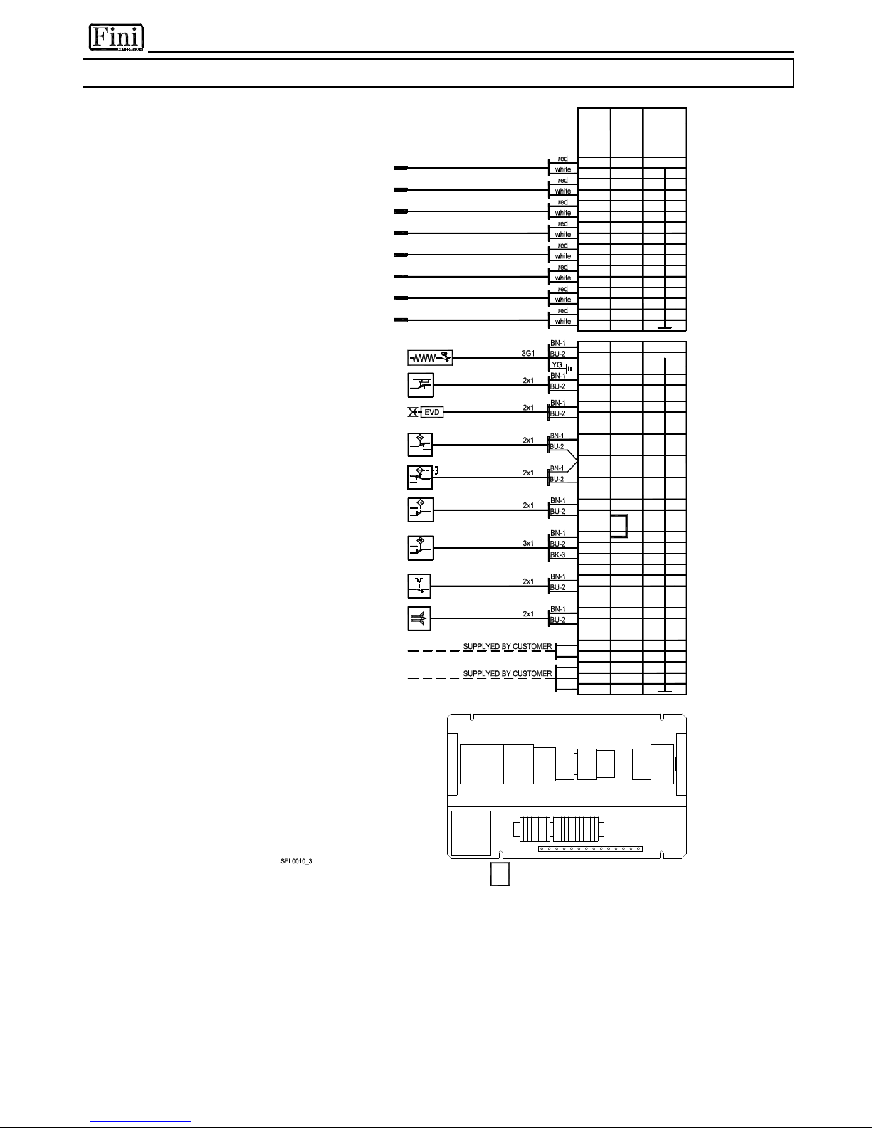
40069 Zola Predosa (BO) - ITALY
7.3.12 RD 480-810 - DMC20
19
18
14
10
9
15
OPTIONAL - ELECTRONIC LEVEL DRAINER
FAN CONTROL PRESS. SWITCH - LOW SPEED
P
V
1
NOT INSTALLED FOR WATER COOLED
20
36
29
11
37
REMOTE ALARM ON INDICATION
START/STOP REMOTE CONTROL
35
22
FAN CONTROL PRESS. SWITCH - HIGH SPEED
NOT INSTALLED FOR WATER COOLED
17
16
12
16
FAN THERMAL PROTECTION
T
V
20
NOT INSTALLED FOR WATER COOLED
P
V
2
20
31
40
41
42
12
13
22
21
TF
1
3
-
1
4
T
7
T
6
T
5
T
2
T
1
T
3
T
4
1
-
2
9
-
1
0
1
1
-
1
2
5
-
6
3
-
4
7
-
8
T
8
2
1
-
2
2
1
5
-
1
6
1
7
-
1
8
1
9
-
2
0
DMC20RI
Q2Q3
V1 V2
S
E
Z
K
Q1
-
MOUNTING PLATE
24
23
2
3
-
2
4
TS
NOT INSTALLED IF OPTIONAL ELECTRONIC DRAINER IS USED
FAN DOOR INTERLOCK SAFETY-SWITCH
CONDENSATE DRAIN VALVE
T5.COMPRESSOR DISCHARGE (HIGH) SIDE
T4.COMPRESSOR SUCTION (LOW) SIDE
COMPRESSOR CRANKCASE HEATER
T
Y
P
E
W
I
R
E
T
E
R
M
I
N
A
L
T
E
R
M
I
N
A
L
T6.CONDENSING
BRIDGE IF NOT INSTALLED
(WATER COOLED ONLY)
T7.AMBIENT
T8.WATER IN
S
D
R
T3.AIR OUT
T1.DEW-POINT
T2.AIR IN
whiteT6
T7
T7
T8
T8
1
3
5
6
4
2
18 UKK 5
16
50
39
12
12
red
white
white
red
T6
T4
T5
T5
T2
T3
T3
T1
T1
T2
T4
red
red
red
white
white
white
red
white
white
red
red UKK 5
COMPRESSOR SUCTION (LOW) SIDE
SAFETY PRESSURE SWITCH
COMPRESSOR DISCHARGE (HIGH) SIDE
SAFETY PRESSURE SWITCH
P
A
P
B
208
7 21
Page 54

40069 Zola Predosa (BO) - ITALY
--------------------------------------------------------------------------------------------------------------------------------
The access code to the 2 level is :
20
--------------------------------------------------------------------------------------------------------------------------------
EN
 Loading...