

Fini MEGA SD 75, MEGA SD 60, MEGA SD 50 Instruction And Maintenance Manual
Manuale d’uso e manutenzione
Betriebs- und Bedienungshandbuch
Manuel d’utilisation et d’entretien
Instructie- en onderhoudshandleiding
Instruction and maintenance manual
Manual de uso y mantenimiento
Manual de uso e manutenção
Bruks- och underhållsanvisning
Руководство по эксплуатации и обслуживанию
Instrukcja użytkowania i konserwacji
ПДЗГЙЕУ ЧСЗУЗУ КБЙ УХНФЗСЗУЗУ
GB
MEGA SD
50-60-75
MEGA SD - Cod.197DD8100 - Rev.0 01/2012

I -
Dichiara sotto la sua esclusiva responsabilità, che il
compressore d'aria qui di seguito descritto è conforme alle
prescrizioni di sicurezza delle direttive: 2006/42/CE,
2000/14/CE, 2006/95/CE, 2004/108/CE, 2009/105/CE, EN
1012-1, EN 60204-1, EN 60335-1, EN 61000-6-3/4.
GR
:
2006/42/EE, 2000/14/EE, 2006/95/EE, 2004/108/EE,
2009/105/CE, EN 1012-1, EN 60204-1, EN 60335-1, EN
61000-6-3/4.
GB -
Declares under its sole responsibility that the air
compressor described below complies with the safety
requirements of directives: 2006/42/EC, 2000/14/EC,
2006/95/EC, 2004/108/EC, 2009/105/EC, EN 1012-1, EN
60204-1, EN 60335-1, EN 61000-6-3/4
PL
- Oświadcza pod pełną własną odpowiedzialność, Ŝe
opisana niŜej spręŜarka powietrzna odpowiada wymaganiom
bezpieczeństwa zawartym w Dyrektywach 2006/42/EC,
2000/14/EC, 2006/95/EC, 2004/108/EC, 2009/105/EC, EN
1012-1, EN 60204-1, EN 60335-1, EN 61000-6-3/4
F -
Déclare sous son entière responsabilité que le
compresseur d’air décrit ci-après est conforme aux
prescriptions de sécurité des directives : 2006/42/CE,
2000/14/CE, 2006/95/CE, 2004/108/CE, 2009/105/CEE, EN
1012-1, EN 60204-1, EN 60335-1, EN 61000-6-3/4..
CZ
- prohlašuje s plnou odpovědností, že uvedený vzduchový
kompresor vyhovuje bezpečnostním požadavkům směrnic
2006/42/ES, 2000/14/ES, 2006/95/ЕS
,
2004/108/ЕS
,
2009/105/ES, EN 1012-1, EN 60204-1, EN 60335-1, EN
61000-6-3/4.
D -
Erklärt unter ihrer alleinigen Verantwortung, daß der in Folge
beschriebene Luftkompressor den Sicherheitsvorschriften der
Richtlinien: 2006/42/EG, 2000/14/EG, 2006/95/EG, 2004/108/EG,
2009/105/EG, EN 1012-1, EN 60204-1, EN 60335-1, EN 61000-6-3/4..
SK
- Zodpovedne vyhlásuje, že uvedený vzduchový kompresor
zodpovedá bezpečnostným požiadavkám smerníc 2006/42/ES,
2000/14/ES, 2006/95/ES, 2004/108/ES, 2009/105/ES, EN
1012-1, EN 60204-1, EN 60335-1, EN 61000-6-3/4.
E -
Declara bajo su exclusiva responsabilidad que el
compresor de aire descrito a continuación responde a las
prescripciones de seguridad de las directivas : 2006/42/CE,
2000/14/CE, 2006/95/CE, 2004/108/CE, 2009/105/CEE, EN
1012-1, EN 60204-1, EN 60335-1, EN 61000-6-3/4
H
- Teljes felelısségének tudatában tanúsítja, hogy az
alábbiakban jellemzett légkompresszor a 2006/42/EC,
2000/14/EC, 2006/95/
ЕС, 2004/108/ЕС, 2009/105/EC, EN
1012-1, EN 60204-1, EN 60335-1, EN 61000-6-3/4
NL -
Verklaart onder zijn eigen verantwoordelijkheid dat de
hieronder beschreven luchtcompressor in overeenstemming is
met de veiligheidsvoorschriften van de richtlijnen: 2006/42/EG,
2000/14/EG, 2006/95/EG, 2004/108/EG, 2009/105/EG, EN
1012-1, EN 60204-1, EN 60335-1, EN 61000-6-3/4
LT
- Su visa atsakomybe pareiškia, kad žemiau aprašytas oro
kompresorius atitinka saugumo direktyvų 2006/42/ES,
2000/14/ES, 2006/95/ES, 2004/108/ES, 2009/105/ES, EN
1012-1, EN 60204-1, EN 60335-1, EN 61000-6-3/4
N -
Erklærer under eget ansvar at luftkompressoren her beskrevet
er i overensstemmelse med sikkerhetsforskriftene i direktivene:,
2006/42/EC, 2000/14/EC, 2006/95/EC, 2004/108/EC, 2009/105/EC,
EN 1012-1, EN 60204-1, EN 60335-1, EN 61000-6-3/4..
LV
- Apliecinā zem savas pilnīgas atbildības, ka apakšā
aprakstītais gaisa kompresors atbilst direktīvu 2006/42/EC,
2000/14/EC, 2006/95/ЕС, 2004/108/ЕС, 2009/105/EC, EN
1012-1, EN 60204-1, EN 60335-1, EN 61000-6-3/4..
S -
Försäkrar under eget ansvar att den luftkompressor som
beskrivs följande är i överensstämmelse med
säkerhetsföreskrifterna i EU-direktiv: 2006/42/EG, 2000/14/EG,
2006/95/EG, 2004/108/EG, 2009/105/EG, EN 1012-1, EN
60204-1, EN 60335-1, EN 61000-6-3/4..
EST
- Avaldab enda täieliku vastatusega, et edaspidi
kirjeldatud õhukompressor vastav ohutuse nõudmistele
direktiividele 2006/42/CE, 2000/14/CE, 2006/95/CE
,
2004/108/CE, 2009/105/CE, EN 1012-1, EN 60204-1, EN
60335-1, EN 61000-6-3/4.
DK -
Forsikrer på eget ansvar, at luftkompressoren, der
beskrives nedenfor, er i overensstemmelse med
sikkerhedsforskrifterne i direktiverne: 2006/42/EC, 2000/14/EC,
2006/95/EC, 2004/108/EC, 2009/105/EC, EN 1012-1, EN
60204-1, EN 60335-1, EN 61000-6-3/4..
SLO
- Na lastno odgovornost izjavlja, da je spodaj opisani
zračni kompresor v skladu z varnostnimi predpisi, ki veljajo za
stroje 2006/42/EU, 2000/14/EU, 2006/95/EU, 2004/108/EU ,
2009/105/EU, EN 1012-1, EN 60204-1, EN 60335-1, EN
61000-6-3/4..
P -
Declara sob a sua exclusiva responsabilidade que o
compressor de ar descrito a seguir está em conformidade com
as prescrições de segurança das directivas: 2006/42/CE,
2000/14/CE, 2006/95/CE, 2004/108/CE, 2009/105/CEE, EN
1012-1, EN 60204-1, EN 60335-1, EN 61000-6-3/4
RO –
Declara pe propria raspundere ca,compresorul de aer
denumit in continuare,este in conformitate cu cerintele de
securitate cuprinse in directivele:2006/42/CE, 2000/14/CE,
2006/95/CE, 2004/108/CE
,
2009/105/CE, EN 1012-1, EN
60204-1, EN 60335-1, EN 61000-6-3/4.
FI -
Vakuuttaa, että seuraavassa esitelty ilmakompressori
vastaa alla lueteltujen direktiivien turvallisuusvaatimuksia:
2006/42/EC, 2000/14/EC, 2006/95/EC, 2004/108/EC,
2009/105/EC, EN 1012-1, EN 60204-1, EN 60335-1, EN
61000-6-3/4..
RU -
Заявляет под свою полную ответственность, что
нижеописанный воздушный компрессор соответствует
требованиям
безопасности согласно директивам
2006/42/EC, 2000/14/EC, 2006/95/ЕС, 2004/108/ЕС,
2009/105/EC, EN 1012-1,EN 60204-1,EN 60335-1,EN 610006-3/4
GB
The following declaration is attached to the compressor in original copy.
All identification data: manufacturer, model, code and serial number are stamped on EC label.
For any request for copies it is ESSENTIAL to provide ALL the data stamped on EC label.
2
2
MEGA SD - Cod.197DD8100
DECLARATION OF CONFORMITY

MEGA SD - Cod.197DD8100
GENERAL INFORMATION
INDEX
DECLARATION OF CONFORMITY .................................2
GENERAL INFORMATION ...............................................3
OVERALL DIMENSIONS ................................................. 4
SAFETY INDICATIONS .................................................... 6
INSTALLATION ................................................................8
TECHNICAL FEATURES ............................................... 11
START-UP AND OPERATION ........................................ 12
MAINTENANCE .............................................................36
TROUBLE SHOOTING ..................................................40
WIRING DIAGRAM ........................................................41
GB
OUTFIT
The following accessories are supplied with the compressor:
• use and maintenance manual
• electric box panel key
• oil/condensate exhaust tube
Check that the above accessories are available. Once the goods have been delivered and accepted, no complaints are
accepted.
CONDITION OF THE MACHINE WHEN SUPPLIED
Every compressor is shop tested and delivered ready to be installed and to be set at work.
Oil used is: ROTENERGY PLUS.
3

1560
840
950
150
70
1590
625
150
70
163
93
GB
OVERALL DIMENSIONS
4
4
MEGA SD - Cod.197DD8100

1560
950
150
70
1590
660
660
150
70
150
70
160
510
150
70
163
200
723
260
MEGA SD - Cod.197DD8100
OVERALL DIMENSIONS
GB
5

GB
SAFETY REGULATIONS
GENERAL WARNINGS
• The rotating compressors are destined for arduous and continuous industrial use. They are particularly adapt for application
in industries where a large consumption of air is requested for long periods of time.
• The compressor must be used exclusively as indicated in this manual, which must be kept carefully in an easily accessible
place known to everyone, as it must remain with the machine for its entire duration.
• The company in which the compressor is to be installed must appoint a person in charge of the compressor itself. Controls,
adjustments and maintenance interventions are under his responsibility: if this person must be replaced, the substitute must
read the user and maintenance manual and any notes made regarding technical and maintenance interventions carried out up
to this time.
SYMBOLS USED IN THE MANUAL
Several symbols have been used inside the manual, which highlight dangerous situations, give practical advice or simple
information. These symbols are found at the side of a text, at the side of a figure or at the top of a page (in this case they refer
to all subjects considered on the entire page).
Pay attention to the meaning of the symbols.
ATTENTION!
Highlights an important description regarding:
technical interventions, dangerous conditions,
safety warnings, advice and/or very important
information.
MACHINE AT A STANDSTILL!
Every operati on highlighted b y thi s symbol
must only be carried out with the machine at a
standstill.
REMOVE VOLTAGE!
It is compulsory to deactivate the electric power
supply to the machine before carrying out any
interventions on the machine.
SPECIALISED STAFF!
All interventions highlighted with this symbol
must be carried out exclusively by a specialised
technician.
SYMBOLS USED ON THE COMPRESSOR
Several different labels are applied to the compressor. Their function is most of all to highlight any hidden dangers and to indicate
correct behaviour during use of the machine or in particular situations.
It is of fundamental importance that they are respected.
Warning symbols Prohibition symbols
High temperature risk
Electric shock risk
Do not open hatches when the machine is
functioning
If necessary, always use the emergency stop
button and not the line isolating switch
Risk from hot or dangerous gases in the work
area
Pressurised container
Obligation symbols
Do not use water to put out fires on electrica
appliances
read this page carefully before carrying out any intervention on the compressor
Carefully read the user instructions
6
6
Moving mechanical parts
Maintenance in progress
Machine with automatic start-up
MEGA SD - Cod.197DD8100

1 2
3
5
4
6
MEGA SD - Cod.197DD8100
SAFETY REGULATIONS
TO DO:
Make sure that mains voltage corresponds to the voltage indicated on CE plate and that cable of suitable cross-section are
used for electric connections.
Always check oil level before starting the compressor.
Be familiar with emergency stop control
Unplug the connector before any maintenance work, so to avoid accidental start.
Ensure that all parts have been correctly reassembled after any maintenance work.
Keep children and animals off the working area to avoid injuries caused by devices connected to the compressor.
Ensure that temperature of the working environment ranges between +2 and + 45 ºC. Compressor working temperature shall
range between 70÷85°C (20-25°C room temperature). Lower temperatures may causes condensate accumulation inside the oil
separator tank (inside the compressor). Check for condensate and if necessary, drain it (see maintenance).
The compressor should be installed and operated in a non-explosive environment.
Allow at least 80 cm between the compressor and the wall so to allow free air flow to the fan.
Press the emergency button on the control panel only in case of actual need so as to avoid possible damages to people or the
very compressor.
When calling for technical assistance and/or advice, always mention model, code and serial number indicated on CE plate.
Always follow the maintenance schedule specified in the user’s guide.
DO NOT:
Do not touch inner parts and pipes as they are very hot during compressor operation and stay hot for a certain time after
compressor stops.
Do not position inflammable close to and onto the compressor.
Do not move the compressor when the tank is under pressure.
Do not operate the compressor if the power cable is damaged or defective or if connection is unstable.
Do not operate the compressor in wet or dusty environments.
Never aim the air jet at people or animals.
Do not allow unauthorized people to operate the compressor and give them all required instructions.
Do not hit fans with blunt objects as they might break during compressor operation.
Never operate the compressor without air filter.
Do not tamper with safety and adjusting devices.
Never operate the compressor when doors/panels are open or removed.
Do not strike the fans with contusive or metal objects as they could cause sudden breakage during functioning.
Do not allow the compressor to function without the filter and/or air pre-filter.
Do not tamper with safety and adjustment devices.
Never allow the compressor to function with the hatches/panels open or removed.
and all other controls.
GB
PRODUCT IDENTIFICATION
The compressor Your have purchased has its own CE plate showing the following data:
1) Manufacturer’s data
2) CE mark – year of manufacture
3) TYPE = name of the compressor
CODE = compressor code
SERIAL NO. = serial number of the compressor You have purchased (to be always mentioned when calling for technical
assistance)
4) max. operating pressure (bar and PSI) – compressor noise level in dB(A)
5) electric data: voltage (V/ph), frequency (Hz), absorption (A) - power (HP and kW), rotations per minute (Rpm).
6) other approvals
read this page carefully before carrying out any intervention on the compressor
7

6
9
8
12
1
5
1
11
7
8
13
15
14
10
10
3
2
4
GB
INSTALLATION
DESCRIPTION OF THE COMPRESSOR
1
8
8
MEGA SD - Cod.197DD8100
MEGA SD - Cod.197DD8100
INSTALLATION
DESCRIPTION OF THE COMPRESSOR
1) Electrical equipment
2) Front panel / Oil indicator level
3) Lid
4) Electric fan
5) Oillter
6) Oilseparatorlter50-60:N°1
Oilseparatorlter75:N°2
7) Minimum pressure valve
8) Oil separator tank
UNPACKING AND HANDLING THE MACHINE
When delivered, compressor top is protected by cardboard packing.
Wear suitable protective gloves and then cut outer straps and then remove cardboard from the top. Check the (outer) good
condition of the machine before moving the compressor. Visually check that no parts are damaged. Also ensure that all accessories
are available.
Lift the machine using a fork lift truck. Fit the anti-vibration elements into their proper seat and move the machine to the room
chosen for its location with maximum care.
Keep all packing materials at least for the warranty period for possible moving. In case of need, it will be safer for delivery to the
technical assistance dept.
Then, dispose of packing materials in compliance with current laws.
9) Airlter
10) Air/Oil radiator
11) Electric motor
12) Control panel
13) Air intake outlet
14) Suction regulator
15) Screw compressor
GB
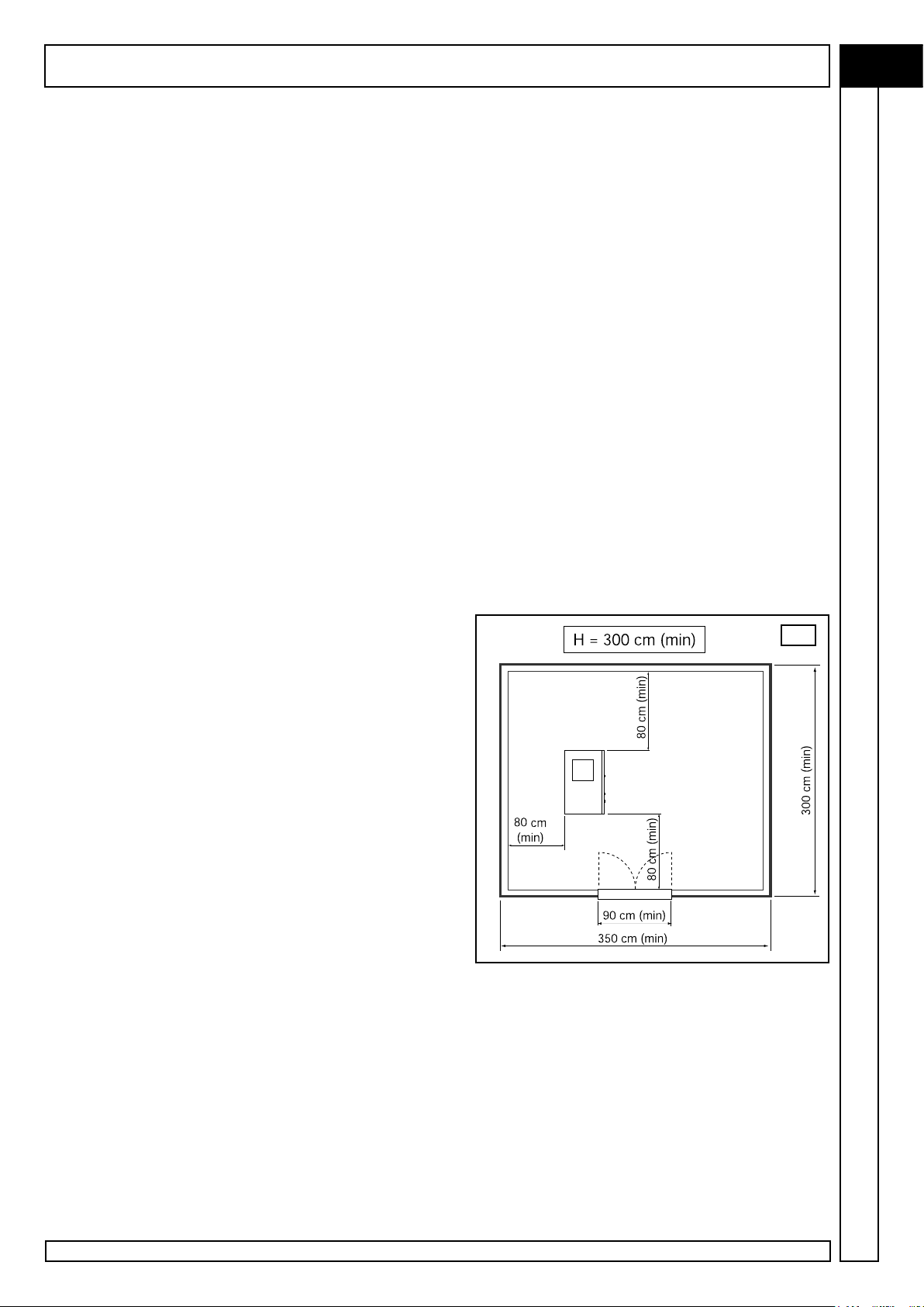
LOCATION (g. 2)
The room chosen for the installation of the compressor should meet
the following requirements and comply with what is specified in the
current safety and accident prevention regulations:
• low percentage of fine dust,
• proper room ventilation and size that allow room
temperature under 45° C. In the event of inadequate hot air
discharge, fit the exhaust fans as high as possible.
Condensate should be collected either into a container or a tank,
or a water/oil separator should be fitted.
CONDENSATE IS A POLLUTING MIXTURE! It must not be let
into the sewage.
The dimensions of the spaces are indicative only but it is advisable
to follow them as closely as possible.
2
9

GB
INSTALLATION
ELECTRICAL HOOK-UP (g. 3)
• The mains cable should have a cross-section suitable
for the machine power and should include no. 3 phase
wires, no. 1 neutral cable and no. 1 earth wire.
• Between the mains cable and the compressor control panel
a fused switch near the point where the cables go into the
machine is absolutely necessary. The switch should be at
least at 1.7 m from the ground.
• The switch (A) should be easily reached by the operator.
The cables should be of the approved type and installed with
the following grade of protection: minimum IP44.
N.B. To determine the cables cross-section and the type of
switch refer to the data reported on the technical table. Sizing
according to “VDE 0100, Part 430 and 523”, star-delta starter,
30° C ambient temperature and cable length lower than 50
meters.
Electric connection 400 V 50 60 75
Conductor min. section mm2 4G25 4G35 4G50
Magnetic thermal switch A 80 100 125
Fuses Agl 80 100 125
3
10
10
MEGA SD - Cod.197DD8100

MEGA SD - Cod.197DD8100
TECHNICAL FEATURES
GB
Technical characteristics
Working pressure
Air-end
F.a.d. (according ISO 1217 annex C)
Oil quantity
Oil quantity for topping-upmains
Max nal air temperature above ambient
Re-claimable heat
Fan ow rate
Oil carry over
Electric motor
Rated power
Max. power absorbed, ventilation included
Electrical box protection class
Maximum ambient temperature
Noise level (according Pneurop/Cagi PN2CPTC2)
Electrical data
Voltage
Auxiliary voltage
Start-up absorbed current
Max. absorbed current, ventilation included
Idle running absorbed power
Electrical motor protection class
Motor insulation class
Service factor
50 60 75
bar g 7,5 10 13 7,5 10 13 7,5 10 13
type END 12 END 12 CF90D4
l/min 6000 5300 4000 7200 6500 5100 8600 7800 6400
l 22,5 22,5 22,5
l 3,5 3,5 3,5
°C 8 10 11
kJ/h 126540 153900 188000
m3/h 5000 5500 5500
mg/m3 2-4 2-4 2-4
type 200 B3 225 B3 250B3
kW 37 45 55
kW 41 50 60
IP 54 54 54
°C +2/+45 +2/+45 +2/+45
dB(A) 70 72 74
V/Ph 400-3 400-3 400-3
V/Ph 24/1 24/1 24/1
Amp 140 180 200
Amp 65 80 97
kW 11,5 13,5 15,5
IP 55 55 55
F F F
1,1 1,1 1,1
Protection devices
Max oil temperature
Pre-alarm oil temperature
Motor overload switch setting
Safety valve setting
Dimensions
Length
Width
Height
Weight
Air outlet size
°C 110 110 110
°C 105 105 105
Amp PTC PTC PTC
bar 14 14 14
mm 1590 1590 1590
mm 950 950 950
mm 1560 1560 1560
kg 870 910 952
Rp
1-1/2” 1-1/2” 1-1/2”
11

GB
START-Up AND OpERATION
1 - CHECKS TO BE CARRIED OUT PRIOR TO START-UP
N.B.: The customer is responsible for installing the machine and making the required electrical and air connections.
Initial system start-up must be carried out by skilled personnel who will make the various checks required and follow
the respective instructions.
Each machine was thoroughly tested at the plant before shipping.
You should monitor the compressor during the first hours of operations to check for faults.
• Follow the installation prescriptions given in the previous chapters.
• Remove all packaging materials and tools.
• Connect the compressor to the distribution line as shown in paragraphs 6.2 and 6.3.
• Check the oil level in the tank: refer to section “Maintenance, oil control and topping up.” In the event of low oil level, top up
with rot-energy plus.
• Check for correspondence between the compressor plate data with the actual specifications of the electrical system.
A variation of ± 10% with respect to the rated value is allowed.
• Connect the machine to the electrical system as described in the previous chapters.
Compliance with the correct voltage phase sequence is
fundamental since this defines the direction of rotation of
the motor. The direction of rotation must be that indicated
by the adhesive labels located to the side of the screw unit
(see picture).
Note that even a few seconds of incorrect rotation may
cause serious damage.
A phase sequence checking device to prevent mistakes is
fitted in the electrical panel.
Before starting the machine read the following sections
and the chapter on maintenance operations for in-depth
knowledge of the machine.
AF1
2 - “NRG” CONTROL PANEL
The compressor is fitted with a “control panel” for setting up and monitoring machine operation. The operating parameters
were entered by the Manufacturer during “testing”. The parameters were tested for several hours in the various operating
conditions.
12
12
The features offered by this electronic control system includes:
• Fully automatic compressor operation.
• Real-time operating parameter display.
• Customization operating parameter.
• Programming of compressor operation on a daily or weekly basis.
• Programming and signalling of the Manufacturer’s maintenance schedule.
• Machine self-protection system to signal fault pre-alarms and automatically stop the machine in the event of serious
problems.
• Remote machine control.
• Possibility of connecting the compressor via CAN-BUS interface (optional) to other similar compressors for integrated management
of the set of machines.
• Remote compressor monitoring via personal computer and dedicated software (optional).
MEGA SD - Cod.197DD8100

B
A
MEGA SD - Cod.197DD8100
START-Up AND OpERATION
GB
The panel has two sections:
A - Control unit “NRG” of the compressor
B - Emergency stop button
2.1 - CONTROL UNIT “NRG”
The front panel of the control unit “NRG” comprises:
• compressor programming and
control keyboard.
• Indicator / setting LEDs.
• back-lit LCD display.
K7
K8
K9
L1
L2
DL
2
K4
K5
K6
L3
K1
K2 L5
K3
L4
Control and programming keyboard
K1 START-button (starting the compressor)
Used to start the machine. If remote control or programming (daily / weekly) are enabled, this key is used to
enable compressor functioning (priority control from keyboard). lf alarm conditions have occurred, pressing
of this key has no effect.
K2 STOP button (stop the compressor)
Permits timed stopping of the machine. If remote control or programming (daily / weekly) have been enabled,
this key can be used to disable compressor functioning (priority control).
It does not operate at emergency level.
K3 RESET button
Makes it possible to reset compressor fault messages after eliminating the causes of these As the faults can
be displayed only in the main screen page, the RESET key is effective only during display of this.
During parameter modification operations, the RESET key-can be used to restore the preset factory (default)
valve for the type of compressor selected.
K4 ESC button
Used to return to the main menu (previous level) or to cancel the modifications made.
If the key is held down, the control unit returns to the main screen page. If OFF, back-lighting of the display is
re-activated the first time the key is pressed without performing any other function.
K5 UP arrow key
Used for upward scrolling of menu items;
during setting of multiple-choice parameters. Makes it possible to select one of the available options.
13
 Loading...