

Page 1
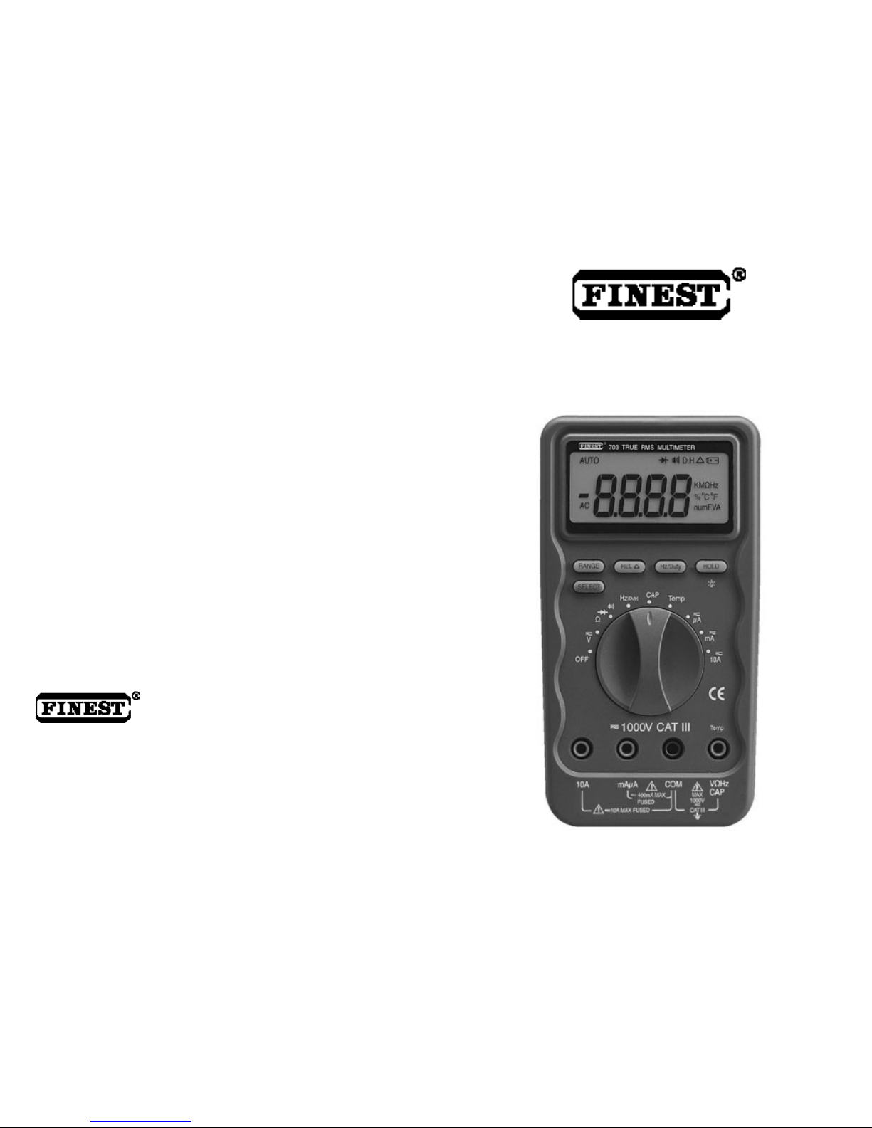
Model 703 True RMS Multimeter
Model 701 Multimeter
USER’S
MANUAL
FINE INSTRUMENTS CORPORATION
FINE INSTRUMENTS CORPORATION
341-5, SONGNAE-DONG, SOSA-GU, BUCHON-SHI, KYUNGGI-DO KOREA
-TEL: (82-32) 656-8771~4 -FAX: (82-32) 656-5844
-E-mail: fine@finest.co.kr
© Copyright 2001 Fine Instruments Corp. All right reserved.
Specifications subject to change without notice.
Litho in Korea.
a world leader in test & measurement
Page 2

SOURCES LIKE S MALL HAND-HELD RADIO
TR ANS CE IVERS, FI XED STA TION RADIO
AND TELEVISION TRANSMITTERS, VEHICLE
RA DI O TRANSM ITTERS AND CE L LUL AR
PHONES GENERATE ELECT ROMAGNETIC
RADIATION THAT MAY INDUCE VOLTAGES
IN THE TEST LEADS OF THE MULTIMETER.
IN SU CH CASES THE ACCURA CY OF T HE
MULT IMETER C ANNOT BE GUARAN TEED
DUE TO PHYSICAL REASONS.
W A R N I N G !
Basic Specifications
DC Voltage : 0 to 1000 V
AC Voltage
703 (True RMS) : 15 mV to 1000 V (@ 40 Hz to 20 kHz)
701 : 0 to 1000 V (@ 40 Hz to 400 Hz)
Basic Accuracy : DC voltage – 0.5%
AC voltage – 0.75%
DC Current : 0 to 10 A (20 A for 30 seconds)
AC Current
703 (True RMS) : 20 µA to 10 A (20 A for 30 seconds)
701 : 0 to 10 A (20 A for 30 seconds)
Resistance : 0 to 40 M
Capacitance : 0.01 nF to 100 µF
Frequency : 0.5 Hz to 10 MHz
Duty Cycle : 0.1 % to 99.9 % for 0.5 Hz to 500 kHz
(pulse width > 2 µsec.)
Diode Test : 2.5 V
Continuity Check : Beep at Approx. < 10 (response time < 1 ms)
Temperature (703 only): –40 C to 1300 C (–40 F to 2372 F)
1. Safety Information 2
2. Electromagnetic Compatibility (EMC) 3
3. Controls and Indicators 4
4. Rotary Switch and Pushbutton Overview 7
5. Meter Operation 9
6. Maintenance 19
7. Specifications 20
Limited Warranty & Limitation of Liability
Warning
Read
Safety Information” before using this Meter.
1
CONTENTS
Page 3

INTERNATIONAL ELECTRICAL SYMBOLS
AC (Alternating Current)
DC (Direct Current)
Either AC or DC
Caution! Refer to the explanation in this manual.
Caution! Dangerous voltage (Risk of electric shock)
Earth (Ground)
Double insulation or Reinforced insulation
Fuse
Not Applicable to Identified Model
Battery
The meters meet EN61326 : 1997+A1: 1998. See the backside of this manual’s
cover page.
This manual contains information and warnings that must be followed for operating
the meter safely and maintaining the meter in a safe operating condition.
If the meter is not used in a man ner specified in this manual, the prote ctio n
provided by the meter may be impaired.
The Model 703 an d Model 701 co mply with IEC 1010-1 (1995), UL 3111-1 (6. 1994),
EN 61010-1 (1995), CSA C 22.2 No, 1010.1 - 92 ; Overvoltage 1000V Category III.
TERMS IN THIS MANUAL
A Warning identifies conditions and actions that could pose serious hazards to the
user. A Caution identifies conditions and actions that co uld cause damage the
meter or the equipment under test.
Warning
Do not expose the meter to rain or moisture in order to reduce the risk of fire or
ele ctric shock. To avoid any e lectrical shock hazard, observe the proper safety
precautions when workin g with voltages above 60 V dc o r 30V ac rms, t hese
voltage lev els p ose a potential sh ock hazard to the user. Inspect test leads,
connectors and probes for damaged insulation or exposed metal before using the
meter. If any defects are found, replace them immediately. Do not touch test lead
tips or the circuit being tested while power is applied to the circuit under test.
Always keep your fingers b ehind the f inger guards of the test leads during
mea surement. Do not m easure any circuit that draws more than the protection
fuse’s current rating. Do not attempt the protection fuse’s voltage rating. Never
attempt a voltage measurement with the test lead inserted into the mA µA or
A
input terminal. When servicing the meter, use only specified replace ment parts.
Remove test leads from the meter before you open the battery door. Do not operate
the meter with the battery door removed or loose ned. To avoid false readings,
which could result in possible electric shock or personal injury, replace the battery
as soon as the low battery indicator appears. Avoid working alone.
Caution
Disconnect the t est l eads from the test points befo re cha nging functions.
Disconnect circuit power and discharge all hig h voltage capacitors before testin g
resistance, continuity, capacitance or diodes. Always set the meter to the highest
range and work downward for an unknown value in the manual ra nging mode.
Before measuring current, check the meter’s fuses and turn power OFF to th e
circuit before connecting the meter to the circuit.
1. SAFETY INFORMATION
2. ELECTROMAGNETIC COMPATIBILITY (EMC)
32
Page 4
Although this manual describes the operation of both Model 701 and Model 703, all
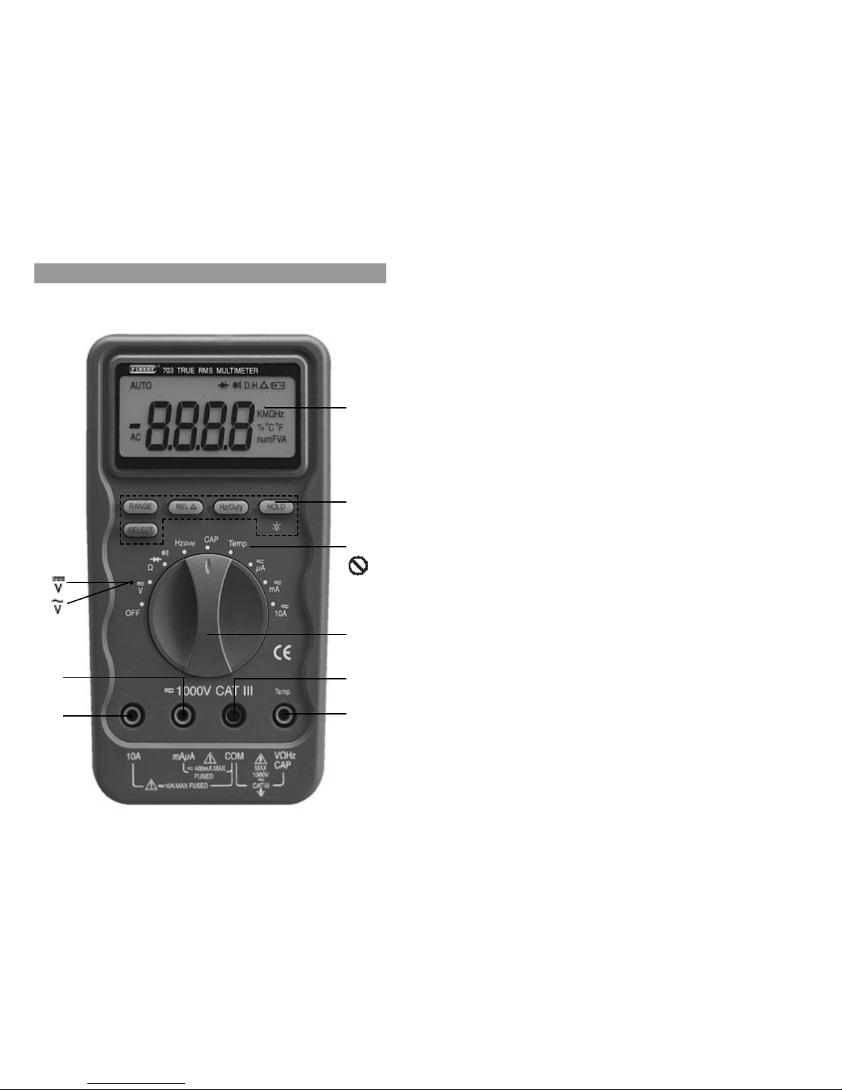
illustrations and examples assume use of Model 703.
(1) 3-3/4 digit, 4000 count LCD display
(2) Push-buttons for special functions & features
(3) Selector to turn the power ON or OFF and select a function
(4) Input terminal for 10A (20A for 30 sec.) current measurement function
(5) Input terminal for milli-amps and micro-amps current measurement function
(6) Common (Ground reference) input terminal for all measurement functions
(7) Input term inal f or all functions EXCEPT current (A, mA, µA) me asurement
functions
Glossary of Terms for Digital Multimeters
Average sensing RMS calibrated
RMS (Root-Mean-Square) is the term used to describe the effective or equivalent
DC value of an AC signal. Most digit al multimeters use a verage sensing RM
S
ca librated technique to measure RMS values of AC signals. This technique is to
obtain the average value by rectifying and filtering the AC signal. The average
value is then scaled upward (that is, calibrated) to read the RMS value of a sine
wave. In measuring pure sinusoidal waveform, this technique is fast, accurate, and
cost effective. However, in measuring non-sinusoidal waveforms, significant errors
ca n be introduced because of different scaling factors relating average to RMS
values.
True RMS
Tru e RMS is a term wh ich identifies a DMM th at accurately responds to the
effective RMS value regardless of the waveform shapes such as square, sawtooth,
triangle, pulse trains, spikes, and transient glitches as well as distorted waveforms
with the presence of harmonics.
( 1 )
( 3 )
( 6 )
( 7 )
( 4 )
( 7 0 1 )
( 5 )
( 2 )
( 7 0 1 )
3. CONTROLS AND INDICATORS
54
Page 5

Non-sinusoidal waveforms may cause :
– Overheated transformers, generator and motors to burn out faster than normal
– Circuit breakers to trip prematurely
– Fuses to blow
– Neutrals to be overheated due to the triplen harmonics present on the neutral
– Bus bars and electrical panels to vibrate
Crest Factor
Crest Factor is the ratio of the Crest (instantaneous peak) value to the True RMS
value, which is commonly used to define the dynamic range of a True RMS DMM.
A pure sinusoidal waveform has a Crest Factor of 1.414.
A badly distorted sinusoidal waveform normally has a much higher Crest Factor.
NMRR (Normal Mode Rejection Ratio)
NMRR is the DMM’s ability to reje ct unwanted AC noise effect which can cause
inaccurate DC measurements. NMRR is typically specified in terms of dB (decibel).
The Meter has a NMRR specification of > 60dB at 50Hz/60Hz, which means a good
ability to reject the effect of AC noise in DC measurements.
CMRR (Common Mode Rejection Ratio)
Common mode voltage is voltage existing o n both the COM and Voltage i n p u t
term inals of a DMM, with respect to ground. CMRR is a DMM’s ability to rejec
t
common mode voltage effect which can cause dig it rattle or offset in voltage
measurements. The Meter has a CMRR specification of > 60dB at DC to 60 Hz in
AC volts measurement function and > 120 dB at DC, 50Hz and 60Hz in DC volts
measurement function.
Burden Voltage
Burden voltage is a voltage drop across the input terminals of a current-measuring
device, caused by internal shunt resistance.
Burden voltage contributes measurement error, and should be as low as practical.
Temperature Coefficient
Temperature Coefficient is a factor use d to calculate t he change in indicatio n or
output of an instrument with changes in temperature.
Un compensated changes in temperature contribute uncertainty by an a mount
determined by the temperature coefficient to instrument.
Turning the Meter On
To turn the meter on, turn the rotary switch from OFF to any switch setting.
Rotary Switch
Turn the meter on by selecting any measurement function. The meter presents a
standard displa y for that function (range, measurement units, etc.). Use the
SELECT button to select any rotary switch alternate function.
When you turn the rotary switch from one function to another, a display for the new
function appears. Button choices made in one fu nction do not carry over int o
another function.
OFF. Turns the meter off.
. (Model 703). Volts ac rms and Volts dc.
. (Model 701). Volts ac.
. (Model 701). Volts dc.
. Access to resistance measurement, continuity test and diode test.
Hz (Duty).
Frequency measurement. Duty cycle is also displayed if it is toggled by
the Hz / Duty button.
CAP. Capacitance measurement.
Temp (Model 703 only). Temperature measurement in degrees Ce ntigrade or
Fahrenheit. Changing the reading mode should be preset at the factory.
. Micro-amps ac rms and micro-amps dc measurements (Model 703).
Micro-amps ac and micro-amps dc measurements (Model 701).
.
Milli-amps ac rms and milli-amps dc measurements (Model 703).
Milli-amps ac and milli-amps dc measurements (Model 701).
4. ROTARY SWITCH AND PUSHBUTTON OVERVIEW
76
Page 6

. Amperes ac rms and amperes dc measurements (Model 703)
Amperes ac and amperes dc measurements (Model 701)
Pushbuttons
The buttons activate features that augment the function selected with the rotary
switch.
RANGE. Use the RANGE button to manually sele ct a range. Press and hold
RANGE button for two seconds to return the meter to auto range mode. The meter
is in auto range mode wh en the A UTO in dica tor is on. The RANGE sele ction
function is not available in Hz (Duty), CAP
, and
Temp modes.
The range and units are displayed on the LCD.
REL¡â. Use this button to set the meter to relative ( ) mode and make relative
mea sure ments. Relative zero allows t he user to offset the meter consecutive
measurements with the displaying reading as the re ference va lue. Pract ically all
displaying readings can be set as relative reference value. Press the REL button
momentarily to activate and to exit relative zero mode.
Hz/Duty. Press this button to toggle between the Hz measurement mode and the
Duty measurement mode when the selector switch is set to Hz (Duty), and
.
HOLD. Press this button to turn hold
mode ON
and OFF. When the
hold mode is
activated, the meter beeps, freezes the display, and displays the D.H indicator on
the LCD. HOLDmode freezes the display for later view.
(Backlight). Press the HOLD ( ) button for two seconds to turn the
backlight ON or OFF, when the HOLD function is simultaneously activated with the
D.H symbol on the display. Press the HOLD button momentarily again to activate
the Backlight function only.
SELECT. Press this button to toggle between the dc measurement mode and the
ac measurement mode when the rotary selector switch is se t to (Model 703
only), , and . And also press this button to cycle through or or
measurement mode when the rotary selector switch is set to .
9
8
5. METER OPERATION
Voltage ( or , ) Measurements
Voltage is the difference in electrical potential between two points.
The polarity of ac (alternating current) voltage varies over time, while the polarity of
dc (direct current) voltage is constant over time.
function defaults at dc. Press SELECT button momentarily to select ac.
Range available in volts functions are :
400 mV, 4 V, 40 V, 400 V, and 1000V
When mea suring voltage, th e meter acts like a 10M (10 x 106) impedance in
parallel with the circuit. This loading effect can cause measurement errors in highimpedance circuits. In most cases, the error is negligible (0.1 % or less) if the circuit
impedance is 10 k or less.
Tips for measuring voltage
In 4 00 mV range, displayed value may fluctuate when disconnecting inpu
t
terminals. This is normal.
AC voltage measuring circuit in Model 703 is of root-mean-square (True RMS)
value system so the meter can accurately measure ac voltage of non-sinusoidal
waveforms including harmonics caused by various non-linear loads.
Page 7

Tips for measuring resistance
Because the meter’s test curren t flows through all possible paths betwe en the
test probe tips, the measured value of a resistor in a circuit is often different from
the resistor’s rated value.
The test leads can add 0.1 to 0.2
of error to resistance measurements.
To measure the resistance of the leads, touch the probe tips together and read
the resistance. If necessary, you can press the REL button to automatically
subtract this value.
The resistance function can produce enough voltage to forward-bias silicon diode
or transistor junctions, causing them to conduct.
Do not use the 40 M range for measuring the in-circuit resistance to avoid this.
Whe n meas uring large resi stance, rea d in g may b e uns tabl e due to
environmentally induced electrical noise. In this case , direct ly connect the
resistor to input terminals of the meter or shield the resistor at potential of the
COM input terminal to obtain stable reading.
For resistance above 1 M , the display may take a few seconds to stabilize. This
is normal for high resistance readings..
The met er h as a circuit to p rotect the resistance range from over-voltage.
However, to prevent accidentally exceeding the protection circuit’s rating and to
ensure a correct measurement, NEVER CONNECT THE LEADS TO A SOURCE
OF VOLTAGE when the rotary switch is set to or or functions.
11
10
To improve the accuracy of dc voltage measurements taken in the presence of
ac voltages (such as, measuring the dc voltage of an amplifier in the presence of
an ac signal), measure the ac voltage first. Note the just measured ac voltage
range a nd select a d c voltage range that is the same or h igher than t he ac
voltage range. This method improves the dc voltage accuracy by preventing the
input protection circuits from being activated.
Resistance ( , , ) Measurements
(Ohms, Diode, and Continuity)
Resistance is an opposition to current flow. The unit of resistance is the ohm ( ).
The meter measures resistance by sending a small current through the circuit.
Ranges available in resistance functions are :
400.0 , 4.000 k , 40.00 k , 400.0 k , 4 M , and 40 M
Warning
To avoid the risk of electrical shock and instrument damage,
input voltages must not exceed 1000 V dc or ac (rms). Do not
attempt to take any unknown voltage measurement that may
be in excess of 1000 V dc or ac (rms).
Caution
To avoid d amaging the meter or the e quipment under test,
re move a ll power f rom the circu it a nd disch arg e all hig hvoltage capacitors before measuring resistance.
Page 8

Frequency (Hz) Measurements
Frequency is the number of cycles a signal completes each second. The m eter
measures the frequency of a voltage or current signal by counting the number of
tim es the signal crosses a threshold level each second.
To measure the frequency of a voltage or current signal, press the Hz/Duty button
momentarily while measuring volts or currents.
The available frequency ranges are 5 Hz, 50 Hz, 500 Hz, 5 kHz, 50 kHz, 500 kHz,
5 MHz and 10 MHz.
Diode ( ) Test
Use the diode test to check dio des, tra nsistors, silicon controlled rectifiers (SCRs),
and othe r sem ic on ductor dev ices. T h e test sends a curr en t thr ough a
semiconductor junction, then me asures the junction’s vo ltage drop.
Normal forward voltage drop (forward biased) for a good silicon diode is between
0.4 V to 0.9 V. A reading higher than that indicates a leaky (defective ) diode. A
zero reading indica tes a shorted (defective) diode.
An indicates an open diode (d efect ive).
Reverse the test leads connectio ns ( reverse biased ) across the dio de.
The display shows if the diode is good. Any other readin gs indicate the diode
is shorted or resistive ( defective )
.
Continuity ( ) Te st
The co ntinuity function detects intermittent opens and shorts lasting as little as 1
millisecond. Th ese brief contacts cause the meter to emit a short beep. This
f
unction is convenient for checking wiring co nnectio ns and operation of switches
.
A continuous beep tone indicates a complete wire.
1312
Caution
Discharge all high-voltage capacitors before testing diodes.
Large value capacitors sh ould be dis charged through an
appropriate resistance load.
Caution
Using resistance and continuity function in a live circuit will
produce false results and may damage the instrument.
In many cases the s uspic iou s c o mpone nts mu s t be
disconnected fro m the circuit under test to obtain accurate
results.
Page 9
Tips for me asuring capacitanc e
Temperature (Temp) Measure ments [Model 703 only]
Tips for measuring freque ncy
In frequency, the meter is always autoranging.
When disconnecting the input term inals, the overload sign may be displayed or
the display may unsteadily fluctuate. This is typical.
Duty Cycle Measurements
Duty Cycle (or Duty Factor) is the percentage of time a signal is above or below a
trigger level during one cycle.
The duty cycle mode is optimized for measuring the ON or OFF time of logic and
switching signals. Systems such as electronic fuel injection systems and switching
power supplies are controlled by pulses of varying width, which can be checked by
measuring duty cycle.
Press the Hz/Duty button to toggle between the Hz mode and the Duty Cycle mode
when the rotary selector knob is set to Hz (Duty), , , , or .
Capacitance Measurements
Capacitance is the ability of a component to store an electrical charge.
The unit of capacitance is the farad (F). Most capacitors are in the nanofarad (nF)
to microfarad (µF) range.
The available capacitance ranges are 40nF, 400 nF, 4 µF, 40 µF, and 100 µF.
1514
Caution
To avoid damaging the meter or the equipment under test,
remove a ll power fro m the circuit and discharge a ll highvoltage capacitors before measuring capacitance.
Large value ca pacitors should be discharged through an
appropriate resistance load. Use the dc voltage function to
confirm that the capacitor is discharged.
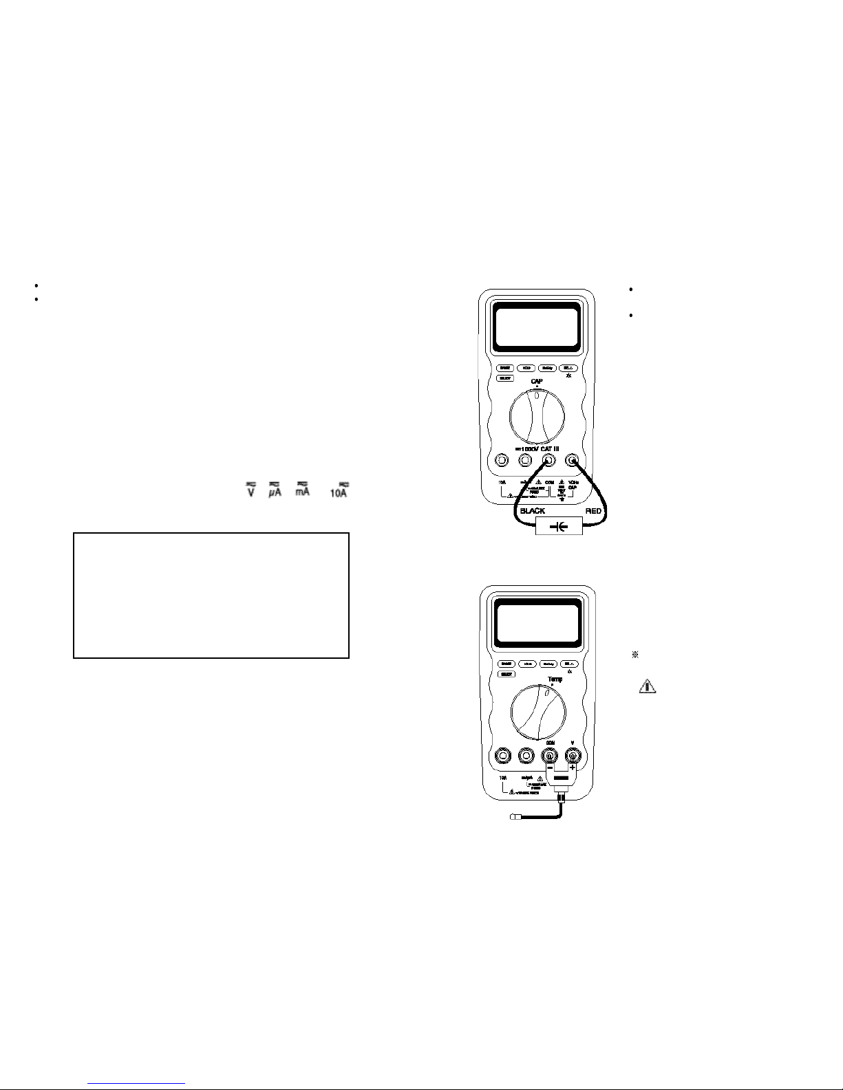
In capacit ance, the Meter is always
a u t o r a n g i n g .
In 40 nF r ange, the readings ar e
probably unstable du e to en vir o nmen tally induced ele ctrical noise and
floating capa city of the t es t le ads.
Therefore, directly connect the object
to be measured to the input terminals.
The me ter c omes wi th temp era t ur e
re ading in either Centigra d e or
Fahrenheit preset at the f actory. The
re ading mode can be c hanged at the
f
act ory only.
The SELECT function is not available
in Temperature mode.
WARNING - Do not a pply
the rmoco u pl e to circuits exceeding
30V rms , 42. 4 V peak or 60V dc.
Be sure to insert the banana p lug K-type
temperature bead probe TP7 with correct
+ – po larities. You ca n als o us e a
thermocou p l e pro be ad a pter T P1 A
(O ptio nal purc hase) to ada p t other
standard K-type temperature probes.
Page 10
1716
4 . Turn on power to the circuit and read the display.
5 . After measuring current, t urn off power to th e circuit and discharge all high-
voltage capacitors. Dis connect the meter and restore the circu it t o normal
o p e r a t i o n .
Tips for measur ing current
When measuring a 3-phase syste m, special attention should be taken to the
phase to phase voltage which is significantly higher than t he phase to earth
volt age. To a vo id e xceedin g the voltage rat in g of t he protecti on fuse(s)
accidentally, always consider the phase to phase voltage as the working voltage
for the protection fuse(s).
When measuring current, the meter’s internal shunt resistors develop a voltage
across the meter’s terminals called “burden voltage”.
This voltage drop may affect precision circuits or measurements.
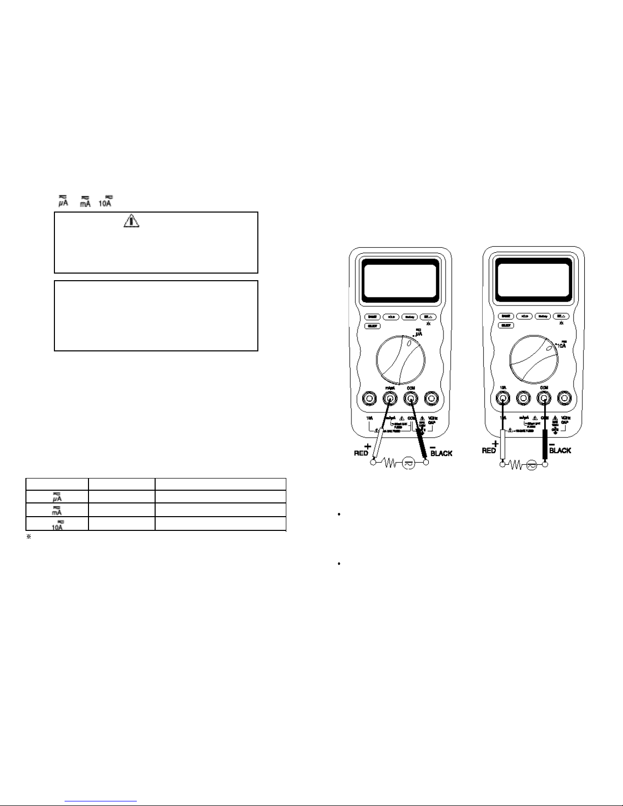
Current ( , , ) Measurements
Current is the flow of electrons through a conductor. To measure current, you must
open the circuit under test, then place the meter in series with the circuit.
The available current ra nges are :
400.0 µA, 4000 µA, 40.00 mA, 400.0 mA, 4.000 A, and 10.00 A
The meter defaults at d c. Press S E L E C T button momentarily to select a c .
To measure dc or
ac current,
1 . Turn off power to the circuit and discharge all high-voltage capacito rs.
2 .Insert the black le ad into the C O M terminal and the red lead into an input
terminal appropriate for the me asurement range as the following table.
To avoid blowing the meter’s 440 mA fuse, use the mAµA terminal only if you are sure the
current is less than 400 mA.
3 . Open the current path to be t ested. Touch the red probe to the more positive
side of the break and touch the black probe to the more negative side of th e
break. (Reversing the leads will produce a negative reading, but will not damag e
the meter.)
Warning
Neve r attempt an in-circuit current measurement where the
open-circuit potential to earth is greater than 1000V. You may
damage the meter or be injured if the fuse blows during such
a measurement.
Caution
Ch eck the meter fuses before measuring current. Use the
proper t erm in als , function, and ra nge for c urrent
measurements. Never place the probes in parallel with any
circuit or component when the test leads are plugged into the
current terminals.
Range RangesInput
mAµA
mAµA
10A
400.0 µA, 4000 µA
40.00 mA, 400.0 mA
4.000 A, 10.00 A
SERIES CONNECTION SERIES CONNECTION
Page 11
1918
Auto / Manual Range Operation
Press the RANGE button momentarily to select manual-ranging in volts, ohms,
and currents measurement function, and the meter will remain in the range it was
in, when the LCD annunciator A U T O turns off.
P
ress the button momentarily again to step through the range s
.
Press and hold the RANGE button for 2 seconds to resume auto- ranging.
Manual-ranging feature is not available in Hz (Duty), CAP, Temp , and
f u n c t i o n s .
Auto - Power - Off
The Auto-Power-Off feature automatically turns the meter off to extend battery life
after approximately 30 minutes of n o activities. To turn on the met er after AutoPower-Off, turn the rotary switch from OFF to any function (ON).
Cleaning and Storage
Perio dica lly wipe the case with a damp cloth and mild detergent; do not use
abrasives or solvents.
Clean the input terminals as follows :
1. Turn the meter off and remove all test leads.
2. Shake out any dirt that be in the terminals.
3. Soak a new swab with alcohol and work the swab around in each terminal.
If the meter is not to be used for periods of longer than 60 days, remove the battery
and store it separately.
Battery and Fuse Replacement
The meter uses a single standard 9V battery (NEDA 1604, JIS006P, IEC 6F 22), a
1000 V/440 mA IR 10 kA fast acting F fuse (F
71
) for mAµA current input, and a 1000
V/11 A IR 10KA fast acting F fuse (F72) for A current input. The (F71) 440 mA, (F72) 11
A fuse must be replaced by qualified service personnel only.
Trouble Shooting
If the meter fails to operate e ven with th e battery or fuse replacements, check it
twice over according to operating procedure as described in this manual.
If the meter’s V/ input terminal has subjected to high voltage transient (caused by
lightning or switching su rge to the system) b y accident or abnormal operating
conditions, the series fusible resistors will be blown off like fuses in order to protect
the user and the meter. Most measuring functions through this terminal will then be
open circuit.
In this case, the series fusible resistors and the spark gaps should be replaced by
qual ified p erson nel. Ref er to the LIMITED WA RRANTY & L I MITAT ION O F
LIABILITY section for obtaining warranty or repairing service.
6. MAINTENANCE
Warning
To avoid electrical shock or personal injury, remove the test
leads and any input signals before replacing the battery or
fuses. To prevent damage or injury, install only the same type
of fuses or equivalents.
Page 12

2120
Safety & Compliances
Maximum voltage between any terminal
and earth ground
: 1000 V ac/dc
Compliances : Complies with CSA C22.2 No 1010.1-92,
ANSI/ISA-S82, 01-94 to 1000 V Overvoltage
Category lll.
Certifications : UL & cUL standard UL 3111-1 Listed
CE-marking certificated
Surge Protection : 8 kV peak per IEC 1010.1-92
Fuse Protection for mA or µA inputs : 1000 V / 440 mA lR 10 kA FAST fuse
Fuse Protection for A input : 1000 V / 11 A lR 10 kA FAST fuse
Physical Specifications
Display (LCD) : Digital – 4000 counts display;updates
5 times/sec.
Operating Temperature : 0 C to 40 C
Storage Temperature : –20 C to 60 C
Temperature Coefficient : nominal 0.15 x (specified accuracy) / C
@(0 C to 18 C or 28 C to 40 C),
or otherwise specified
Relative Humidity : 0 % to 80 % @ (0 C to 35 C)
0 % to 70 % @ (35 C to 40 C)
Altitude : Operating – up to 2000m
Storage – 10000m
Battery Type : Single 9V battery –NEDA 1604, JIS 006P or
IEC 6F 22
7. SPECIFICATIONS
Battery Life : 250 hrs. typical (with backlight off) [703]
750 hrs. typical (with backlight off) [701]
Shock Vibration : Per MIL-T-PRF 28800 for Class II instruments
Pollution Degree : 2
Electromagnetic
Compatibility (EMC) : Susceptibility – Commercial Limits for
EN 50082-1
Emissions – Commercial Limits for EN 50081-1
Size (H x W x L) : 40.5 x 92 x 172 mm
Weight : Approx. 386g
Warranty :
3 years
Calibration Interval : 1 year
Feature Summary
Backlight : For clear readings in poorly lighted areas
Fast Autoranging : Meter automatically selects the best range
momentarily
HOLD
:
Holds readings on display
Continuity / Open test : Beeper sounds
Battery/Fuse Access Door : battery or fuse replaceable without voiding
calibration
High-Impact Overmolded Case : Protective holster features
Page 13

2322
Electrical Specifications
Accuracy is given as ± ([% of reading] + [number of digits]) at 18 C to 28 C with
relative humidity up to 80%, for a period of one year after calibration.
True RMS responding a ccuracie s a re specified from 5% to 100% of range or
otherwise specified; Crest Factor < 3:1 at full scale and < 6:1 at half scale.
DC Voltage
NMRR : > 60dB @ 50/60 Hz
CMRR : > 120 dB @ DC, 50/60 Hz, Rs=1k
Input Impedance : 10 M , 30 pF nominal
(50 M , 100 pF nominal for 400 mV range)
AC Voltage
CMRR : > 60dB @ DC to 60 Hz, Rs = 1 K
Input Impedance
:
10 M , 30 pF nominal
(50 M , 100 pF nominal for 400 mV range)
*1: Accuracy for 400 Hz to 1 kHz
Range
701 703
Accuracy
400 mV 100 µV
0.5 % + 2
0.5 % + 2
4 V 1 mV
0.75 % + 3
40 V 10 mV
400 V 100 mV
1000 V 1 V 0.75 % + 3
Resolution
DC Current
AC Current
Resistance
Open Circuit Voltage : < 1.3 V dc
Range
40 Hz – 400 Hz 400 Hz – 10 kHz
Accuracy
701
703 703
400 µA 0.1 µA
4000 µA 1 µA
1.0 % + 5
40 mA 10 µA
400 mA 100 µA
4 A
1 mA
1.0 % + 5
1.5 % + 10
1.5 % + 10
2.0 % + 10
10 A 10 mA
1.5 % + 5
Resolution
Range
701 703
Accuracy
400 µA
4000 µA
1.0% + 2
40 mA
400 mA
4 A
10 A
0.1 µA
1 µA
10 µA
100 µA
1 mA
10 mA
1.0% + 2
1.5 % + 5 1.5 % + 5
Resolution
Range
40 Hz – 400 Hz 400 Hz – 1 kHz 1 kHz – 20 kHz
Accuracy
701 703 703
400 mV 100 µV
4 V 1 mV
0.75 % + 3
40 V 10 mV
400 V 100 mV
1000 V 1 V 1.0% + 5 1.0 % + 5 2.0% + 5 *1–
0.75 % + 3
2.0 % + 3
Resolution
Range
701 703
Accuracy
400 0.1 1.0 % + 5 1.0 % + 5
1.5 % + 10 1.5 % + 10
1.0 % + 5
1.0 % + 5
4 k 1
0.5 % + 340 k 10
400 k 100
4 M 1 k
40 M 10 k
0.5 % + 3
Resolution
2.0 % + 10 2.0 % + 10
Page 14

Continuity
Diode Test
Capacitance
*1. Accuracy with film capacitor or better
Using
Mode
Frequency and Duty Cycle
25
Temperature (Model 703 only)
* This specification is effective at the ambient temperature of 23 C (73.4 F) only.
Frequency Counter Sensitivity
Burden Voltage ( A, mA, µA)
24
Remark
Accuracy
701 703
Minimum frequency :
0.5 Hz
Sensitivity :
5 Hz–1 MHz, > 250 mV
1 MHz–10 MHz, > 350 mV
0.001 Hz
0.01 Hz
0.05 % + 3
0.05 % + 3
0.1 Hz
1 Hz
10 Hz
Range
5 Hz
50 Hz
500 Hz
5 kHz
50 kHz
500 kHz
100 Hz
5 MHz
1 kHz
10 MHz
10 kHz
0.1%
0.5 Hz to 500 kHz (pulse width > 2 µsec.)
(0.1% + 0.05% per kHz + 1 count) for 5 V input (Logic signals only)
0.1% to
99.9%
Resolution
Function
Burden Voltage (typical)
mA / µA
Range
400 µA
4000 µA
40 mA
400 mA
4 A
10 A
150 µV / µA
150 µV / µA
3.3 mV / mA
3.3 mV / mA
0.03 V / A
0.03 V / A
10 A
Range Accuracy Open Circuit Voltage
4V 2%
Test Current
(Typical)
0.25 mA < 1.5 V dc
Audible threshold : the beeper sounds if the measured resistance is lower than
10 , and turns off when greater than about 60 .
Response time : < 1 msec.
Range
701 703
Accuracy
*
1
2.5 % + 10 2.5 % + 10
40 nF 10 pF
400 nF 100 pF
4 µF 1 nF
40 µF 10 nF
100 µF 100 nF
Resolution
Range Accuracy
- 40 C to -10 C
(-40 F to 14 F)
Resolution
1 C
1 F
3% ± 5 C
(3% ± 5 F)
- 10 C to 400 C
(14 F to 752 F)
1 C
1 F
1% ± 3 C
(1% ± 3 F)
400 C to 1300 C
(752 F to 2372 F)
1 C
1 F
3% of reading
(3% of reading)
Range
Minimum Sensitivity ( RMS Sine Wave )
V
(4 V to 1000 V)
500 mV
40 Hz to 10 kHz 40 Hz to 20 kHz
500 mV
µA
(400 µA to 4 mA)
> 15 % F.S. of AC range Not Specified
mA
(40 mA to 400 mA)
> 15 % F.S. of AC range
Not Specified
A
(4.0 A to 10 A)
> 45 % F.S. of AC range Not Specified
*
1
Page 15

LIMITED WARRANTY & LIMITATION OF LIABILITY
Fine Instruments Corporation (Finest) warrants this product to be free from defects
in material and workmanship under normal use and service for 3 years. This
warranty extends only to the original buyer or end-user customer of a Finest
authorized reseller, and is not applied to fuses, battery or to any product which, in
Finest’s option, has been misused, altered, neglected or damaged by accident or
abnormal conditions of operation or handling.
Finest warrants that software will operate on appropriate Finest instruments
substantially in accordance with its functional specifications for 90 days and that it
has been properly recorded on non-defective media. Finest does not warrant that
software will be error free or operate without interruption.
Finest authorized resellers shall extend this warranty on new and unused products
to end-user customers only but have no authority to extend a greater or different
warranty on behalf of Finest.
Finest’s warranty obligation is limited, at Finest’s option, to refund of the purchase
price, or free of charge repair or replacement of a defective product which is
returned to the Finest’s factory within the warranty period.
To obtain warranty service, contact your nearest Finest authorized reseller or send
the product, with a description of the difficulty, postage and insurance prepaid (FCA
Destination), to the nearest Finest authorized reseller. Finest assumes no risk for
damage in transit. Finishing warranty repair, the product will be returned to Buyer,
transportation prepaid (FCA Destination). If Finest determines that the failure was
caused by misuse, accident, abnormal condition of operation / handing, or
alteration, Finest will provide an estimate of repair costs and obtain authorization
before commencing the repair work. Finishing repair, the product will be returned to
the Buyer transportation prepaid and the Buyer will be billed for the repair and
return transportation charges (FCA shipping Point).
Warranty service is available outside the Republic of Korea only if product was
purchased through a Finest Authorized Sales Outlet in the country of use. Finest
reserves the right to invoice Buyer for importation costs of repair/replacement parts
when product purchased in one country is submitted for repair to the Finest factory
in the Republic of Korea.
DISCLAIMER
THIS WARRANTY IS IN LIEU OF ANY OTHER WARRANTIES, EXPRESSED O
R
IMPLIED, INCLUDING ANY WARRANTY OF MERCHANTABILITY OR FITNESS FOR
A PARTICULAR PURPOSE. FINEST SHALL NOT BE LIABLE FOR ANY SPECIAL
,
INDIRECT, INCIDENTAL OR CONSEQUENTIAL DAMAGES OR LOSSES,
INCLUDING LOSS OF DATA, WHETHER ARISING FROM BREACH OF WARRANTY
OR BASED ON CONTRACT, TORT, RELIANCE OR ANY OTHER THEORY.
 Loading...