

Page 1
500
DIGIT
AL MUL
TIMETER
Please read before using this equipment.
USER’S MANUAL
FINE INSTRUMENTS CORPORATION
341-5, SONGNAE-DONG, SOSA-GU, BUCHON-SHI, KYUNGGI, KOREA
-TEL: (82-32) 656-8771~4 -FAX: (82-32) 656-5844
-E-mail: [email protected]
-Internet: www.finestwon.com (or www.finest.co.kr)
© Copyright 1999 Fine Instruments Corp. All right reserved.
Specifications subject to change without notice.
Litho in Korea.
a world leader in test & measurement
Page 2
SOURCES LIKE SMALL HAND-HELD RADIO
TRANSCEIVERS, FIXED STATION RADIO AND
TELEVISION TRANSMITTERS, VEHICLE RADIO
TRANSMITTERS AND CELLULAR PHONES
GENERATE ELECTROMAGNETIC RADIATION
THAT MAY INDUCE VOLTAGES IN THE TEST
LEADS OF THE MULTIMETER. IN SUCH CASES
THE ACCURACY OF THE MULTIMETER CANNOT
BE GUARANTEED DUE TO PHYSICAL REASONS.
WARNING!
1
Measurement Limits:
DC Voltage : 0.1mV to 1000V
AC Voltage : 1mV to 750V
DC Amperes : 0.1µA to 10A
AC Amperes : 0.1µA to 10A
Resistance : 0.1Ω to 20MΩ
Continuity Check : Beep at Approx. < 150Ω in the 200Ω range
WARNING!
READ “SAFETY CONSIDERATIONS” BEFORE USING THIS
METER.
1. Introduction 2
2. Safety Considerations
3
3. Explanation of Controls and Indicators 5
4. Basic Electrical Tests and Measurements 9
5. Maintenance and Battery/Fuse(s) Replacement 21
6. Accessories 23
7. Specifications 24
CONTENTS
Page 3
Before using this Meter, read the following safety information carefully.
In this manual, the word “WARNING” is used for conditions and actions
that pose hazard(s) to the user; the word “CAUTION” is used for
conditions and actions that may damage this Meter.
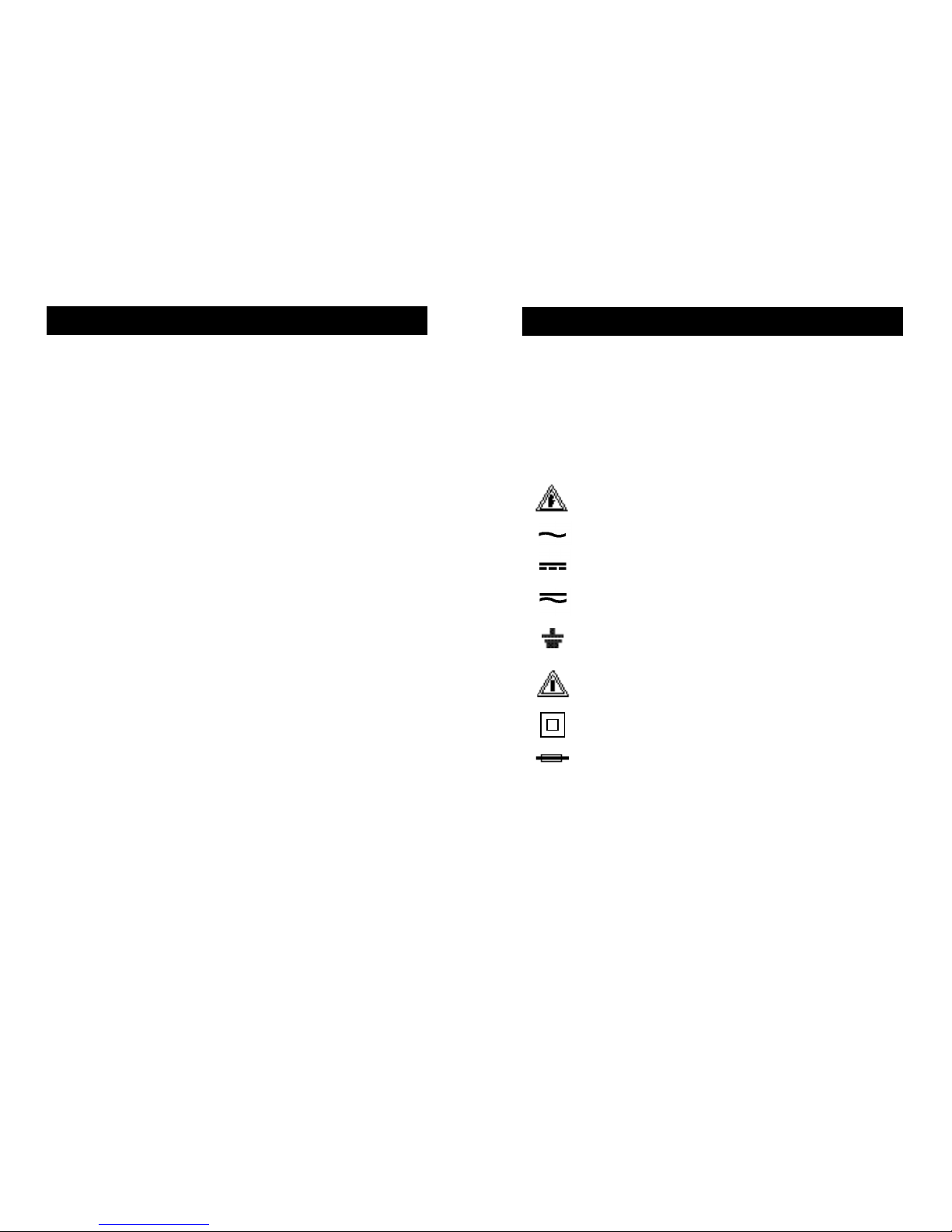
International Symbols
Dangerous Voltage ( Risk of electric shock)
Alternating Current (AC)
Direct Current (DC)
Either DC or AC
Ground (Allowable applied voltage range between the input
terminal and earth)
Caution! Refer to the user’s manual before using this
Meter.
Double Insulation (Protection Class ll)
Fuse
This Meter is a handheld and battery operated instrument that is
designed and tested according to IEC Publication 1010-1 (EN 61010-
1) (Overvoltage Category ll), the EMC Directive (EN 50081-1 and EN
50082-1) and other safety standards (see “Specifications”).
Features:
■Accurate measurements of non-filtered (rectified AC) DC signals
■31/2digit, 2000 count digital display
■Manual ranging
■Fused 10 Amps range
■DC voltage basic accuracy within 0.5%
■Date hold
■Continuity beeper and diode test
■600 volt input protection on ohm range
■Hold and Low-battery annunciators
■Rubber boot (or Safety holster)
■Large LCD display (68.5mm x 32.7mm)
2 3
1. INTRODUCTION
2. SAFETY CONSIDERATIONS
Page 4
4 5
WARNING!
OBSERVE ALL SAFETY PRECAUTIONS WHEN MEASURING
HIGHER VOLTAGES AND/OR CURRENTS. TURN OFF POWER TO
THE CIRCUIT UNDER TEST, SET THIS METER TO THE DESIRED
FUNCTION AND RANGE, CONNECT THE TEST LEADS TO THIS
METER AND THEN TO THE CIRCUIT UNDER TEST. REAPPLY
POWER. IF AN ERRONEOUS READING IS OBSERVED,
DISCONNECT POWER IMMEDIATELY AND RECHECK ALL
SETTINGS AND CONNECTIONS.
Safety Tips:
•
Do not try to measure any voltage that exceeds 1000V DC or 750V
AC RMS.
•
Voltages above 60V DC or 25V AC RMS may constitute a serious
shock hazard.
•
Do not attempt to use this Meter if either the Meter or the test leads
have been damaged.
•
Turn off power to the circuit under test before cutting, unsoldering, or
breaking the circuit. Small amounts of current can be dangerous.
•
Disconnect the live test lead before disconnecting the common test
lead.
•
When using the test leads, keep your fingers away from probe
contacts. Always grip behind the finger guards on the probes.
•
Use a current clamp if measuring any current above 10 Amps.
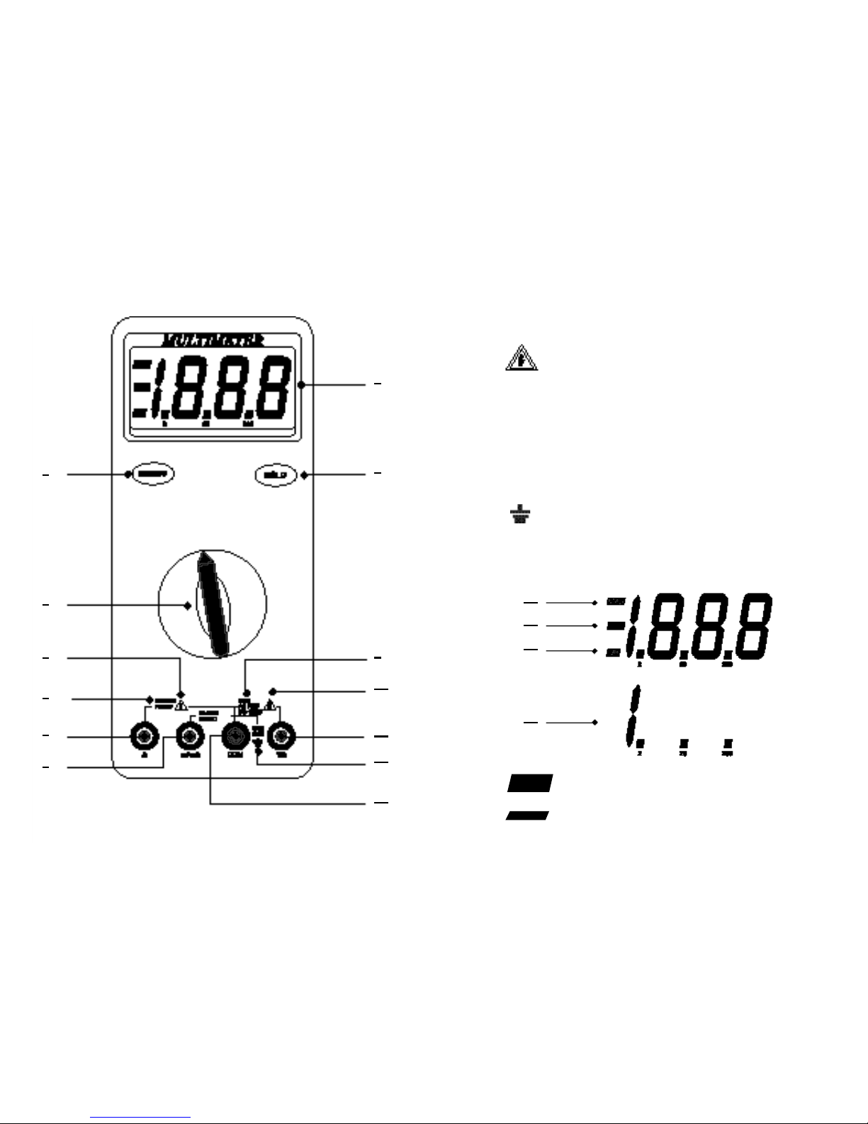
1 – DIGITAL DISPLAY. Digital readings are displayed on a 2000
count display with polarity indication.The display updates three
times per second.
2 – . Selects meter’s power ON or power OFF.
3 – . Freezes reading in digital display.
4 – ROTARY SWITCH. Describes functions that are selected by
setting the rotary switch.
V Volts ac V Volts dc A Amperes ac
A Amperes dc Ω Resistance Continuity Test
Diode Test
5 – . The maximum current that you can measure at this
terminal is 10 Amps DC/AC.
This terminal is fuse
6 – . Refer to the user’s manual before using this Meter.
7 –A(Amperes Input Terminal). The red test lead is plugged into
this terminal for measuring current on the 10A AC or DC current
functions.
8 –
mA µA
(Milliamp/Microamp Input Terminal). The red test
lead is plugged into this terminal for measuring mA or µA on
either AC or DC current functions.
10A MAX
FUSED
3. EXPLANATION OF CONTROLS AND INDICATORS
Page 5
9 –
. The maximum voltage that this Meter can measure
is 1000V DC or 750V AC RMS.
10 – . Be extremely careful when making high-voltage
measurement; DO NOT TOUCH TERMINALS OR TEST LEAD
PROBE ENDS.
11 –VΩ(Volt, Ohms, Diode Test Input Terminal).
The red test lead is plugged into this terminal for all AC V, DC V,
Ohms, Continuity test and Diode test functions.
12 – . To avoid electrical shock or instrument damage, do not
connect the COM input terminal to any source of more
than 600V with respect to earth/ground.
13 –
COM
(Common Terminal). The black test lead is plugged into
this terminal for all measurements.
14 –
HOLD
. Displayed when the HOLD button has been pressed.
15 – (Negative Polarity). Automatically indicate negative
inputs.
6 7
MAX
AC 750V
DC 1000V
MAX
600V
2
1
3
9
11
10
12
13
4
6
5
7
8
14
15
16
17
Page 6

8 9
16 – (Low Battery). Battery run-out warning. When is
first displayed, at least 8 hours of battery life remain. Replace the
battery immediately. Never leave a weak or dead battery in the
Meter. Even leak-proof types can leak and damages the Meter.
17 –
I
...
(Overload Indication). Displayed on the LCD when input
is too large to display.
Using Test Leads
Use only the same type of test leads as are supplied with the Meter.
These test leads are rated for 1200 volts. Although these test leads are
rated for 1200 volts, do not try to measure any voltage greater than
1000 volts DC or 750 volts AC.
NOTE: In some DC and AC voltage ranges with test leads not
connected to any circuits, the display might show
fluctuating readings due to the high input impedance. This
is normal. When you connect the test leads to a circuit, a
real measurement appears.
Using Holster and Stand
The Meter comes with a protective holster that absorbs shocks and
protects the Meter from rough handling. The holster is equipped with a
stand rest.
4.1 Measuring Voltage
WARNINGS!
TO AVOID THE RISK OF ELECTRICAL SHOCK AND INSTRUMENT
DAMAGE, INPUT VOLTAGES MUST NOT EXCEED 1000V DC OR
750V AC (RMS). DO NOT ATTEMPT TO TAKE ANY UNKNOWN
VOLTAGE MEASUREMENT THAT MAY BE IN EXCESS OF 1000V
DC OR 750V AC (RMS).
THIS METER IS DESIGNED FOR MEASUREMENT IN WEAK
CURRENT CIRCUITS. DO NOT USE IT FOR STRONG CURRENT
CIRCUITS (POWER LINE IN FACTORIES AND SO ON HAVING
LARGE CURRENT CAPACITY). USE IN STRONG CURRENT
CIRCUITS IS VERY DANGEROUS BECAUSE SURGE VOLTAGE IN
FAR EXCESS OF RATING IS OFTEN APPLIED TO THEM.
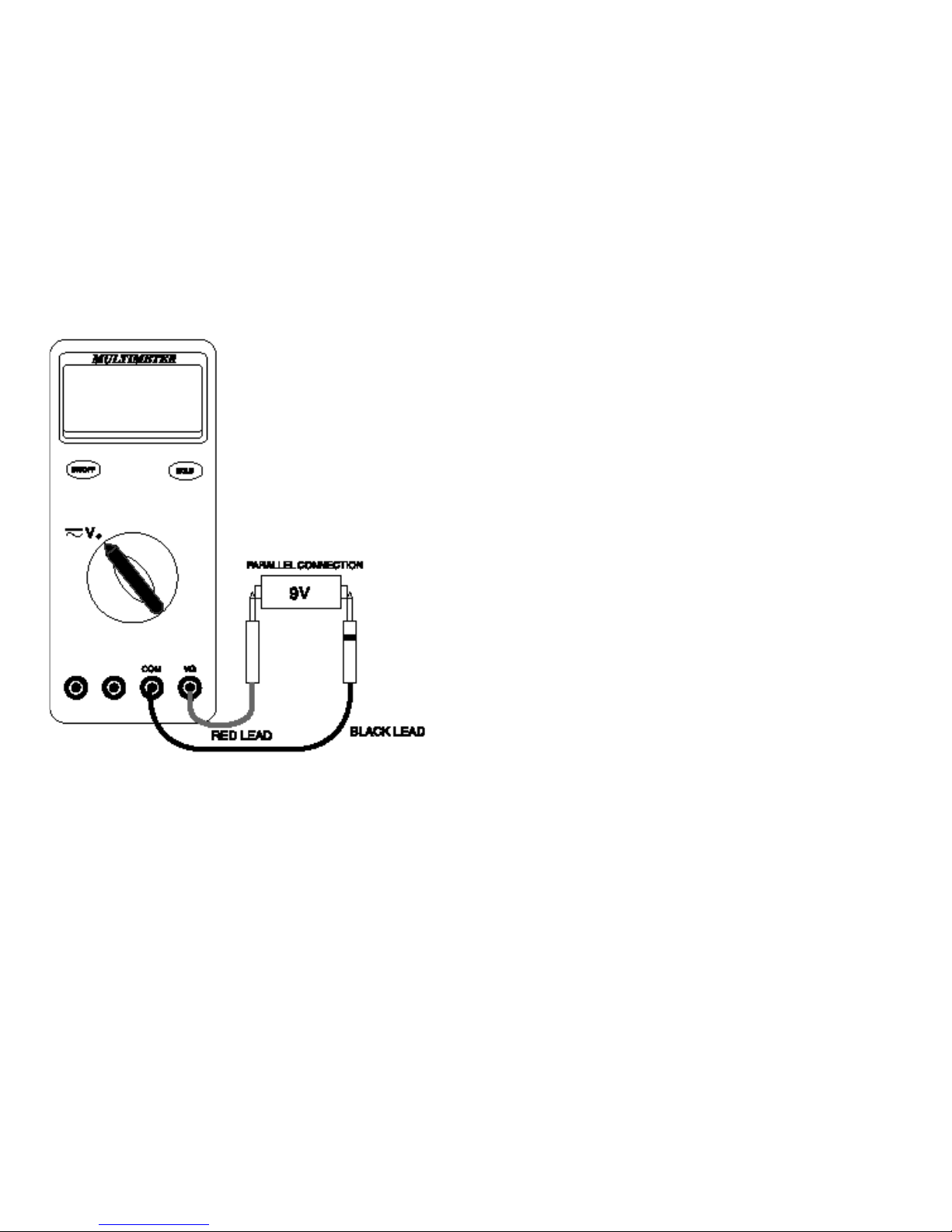
NOTE: When taking voltage measurements, this Meter must be
connected in PARALLEL with the circuit, or circuit
element under test.
4. BASIC ELECTRICAL TESTS AND MEASUREMENTS
Page 7
10 11
• In 200mV range, displayed value may fluctuate when disconnecting
input terminals. This is normal.
• AC voltage measuring circuit in this Meter is of mean value system
so an AC waveform other than a sine wave causes error.
• To improve the accuracy of DC voltage measurements taken in the
presence of AC voltages (such as, measuring the DC offset voltage
of an amplifier in the presence of an AC signal), measure the AC
voltage first. Note the just measured AC voltage range and select a
DC voltage range that is the same or higher than the AC voltage
r
ange. This method improves the DC voltage accuracy by
preventing the input protection circuit from being activated.
Follow these steps to measure DC (or AC) volts.
1. Set function and range switch to the desired DC V (or AC V) range.
If you do not know the value of the voltage to be measured, always
start with the highest range and reduce the setting as required to
obtain a satisfactory reading.
2. Plug the red test lead into the “VΩ” input terminal and the black lead
into the “COM” input terminal of the instrument.
3. Disconnect the power from the circuit to be tested.
4. Connect the test leads to the circuit to be tested.
5. Reapply power to the circuit, the measured voltage will appear on
the display of the instrument.
6. If the red test lead is connected to the negative (or lower voltage)
side of the circuit, a minus sign will appear on the display, at the left.
7. Disconnect power to the circuit before removing the test leads from
the circuit.
Three-Phase AC Volts
This Meter is designed to primarily measure household AC voltage.
When measuring THREE-PHASE circuit line-to-line, the value of the
voltage is actually higher than the rated line-to-ground 3-phase
voltage. It is very important that you do not exceed the maximum AC
(RMS) rating of this Meter, 750V AC.
Page 8
12 13
To find the RMS voltage line-to-line on a 3-phase power line, multiply
the rated line-to-ground voltage by the square root of 3 (approx.
1.732).
For example, if you connect this Meter to a 480 volts 3-phase line
(i.e.480V line-to-ground), the total available voltage line-to-line is about
832V AC (≒480V x 1.732). Severe damage and a dangerous shock
hazard could result because this exceeds the rating of this Meter.
4.2 Measuring Resistance (Ohms, Continuity)
CAUTION!
TURN OFF POWER AND DISCHARGE ALL CAPACITORS ON
CIRCUIT TO BE TESTED BEFORE ATTEMPTING INCIRCUIT
RESISTANCE MEASUREMENTS. FAILURE TO DO SO MAY END
UP IN EQUIPMENT (AND/OR INSTRUMENT) DAMAGE.
THE RESISTANCE MEASURING CIRCUIT APPLIES A KNOWN
VALUE OF CONSTANT CURRENT THROUGH THE UNKNOWN
RESISTANCE AND THEN MEASURES THE VOLTAGE
DEVELOPED ACROSS IT. THEREFORE, REMOVE ALL POWER TO
THE CIRCUIT UNDER TEST WHEN MAKING RESISTANCE
MEASUREMENT. IF ANY VOLTAGE IS PRESENT IN THE TEST
CIRCUIT, AN ERRONEOUS READING WILL RESULT. THIS METER
MAY BE DAMAGED IF VOLTAGE IN EXCESS OF 600V AC IS
PRESENT.
NOTE: When measuring critically low Ohm values, touch tips of
test leads together and record the reading. Subtract this
reading from any additional measurement to obtain the
most accurate value.
• When measuring large resistance, reading may be unstable due to
environmentally induced electrical noise. In this case, directly
connect the resistor to input terminals of the meter or shield the
resistor at potential of the COM input terminal to obtain stable
reading.
Page 9
• For resistance above 1 Megohm, the display might take a few
seconds to stabilize. This is normal for high-resistance readings.
• The Meter has a circuit to protect the resistance range from overvoltage (600V AC). However, to prevent accidentally exceeding the
protection circuit’s rating and to ensure a correct measurement,
NEVER CONNECT THE TEST LEADS TO A SOURCE OF
VOLTAGE when the rotary switch is set to Ω or functions.
• The current applied during resistance measurements could damage
some devices. The table below lists the test voltage and current
available for each resistance measurement range. (All values are
typical.)
NOTE: (A) is the open circuit test voltage at the input terminals in
volts.
(B) is the voltage drop across a resistance equal to full
scale value.
(C) is the current through a short circuit at the input
terminals.
14 15
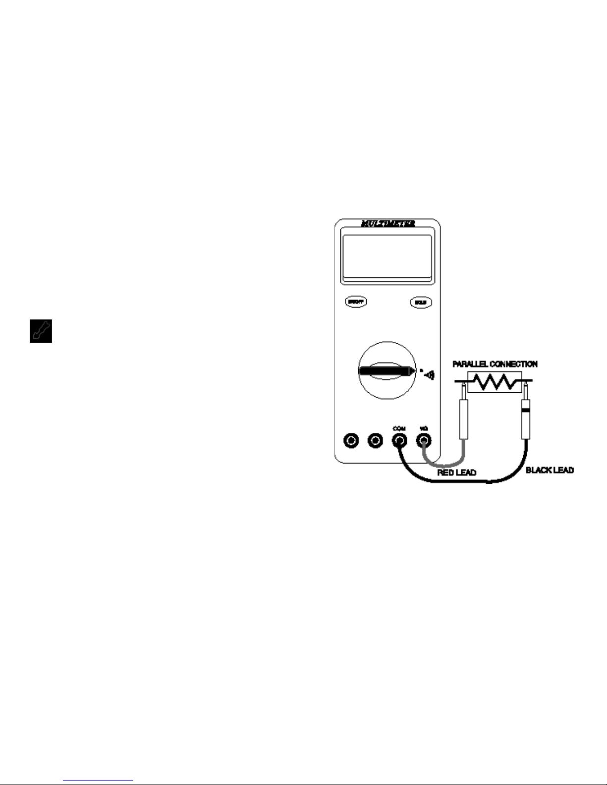
4.2.1 Measuring Ohms
When measuring resistance, be sure that the contact between the test
leads and the circuit under test is good. Dirt, oil, solder flux, or other
foreign matter seriously affect the reading value.
Follow these step to measure ohms.
1. Set the Function switch to the desired “Ω” position.
2. Insert the black test lead into the “COM” input terminal and the red
test lead into the “VΩ” input terminal.
3. Connect the test leads to the circuit to be measured.
4. The measured resistance will be on the LCD.
4.2.2. Continuity Test
This mode helps you check electrical circuits, such as wiring, speaker
cables, connections, switchers, or relays for short or open circuits. In
continuity test, a measured value of approx. 150Ω or less causes the
Meter to emit a continuous tone.
Follow these steps to check continuity
1. Set the Function switch to the “ ” position.
2. Insert the black test lead into the “COM” input terminal and the red
test lead into the “VΩ” input terminal.
3. Connect the test leads to the circuit to be measured.
4. This Meter will emit a continuous tone for resistances of less than
150 ohms.
RANGE OPEN CIRCUIT FULL SCALE SHORT CIRCUIT
VOLTAGE (A)
VOLTAGE (B) CURRENT (C)
200 Ω < 150 mV < 695 µA
2 KΩ < 550 mV < 470 µA
20 KΩ < 1.2 V < 700 mV < 95 µA
200 KΩ < 750 mV < 10.5 µA
2 MΩ < 800 mV < 1.1 µA
20 MΩ < 800 mV < 0.2 µA
Page 10
16 17
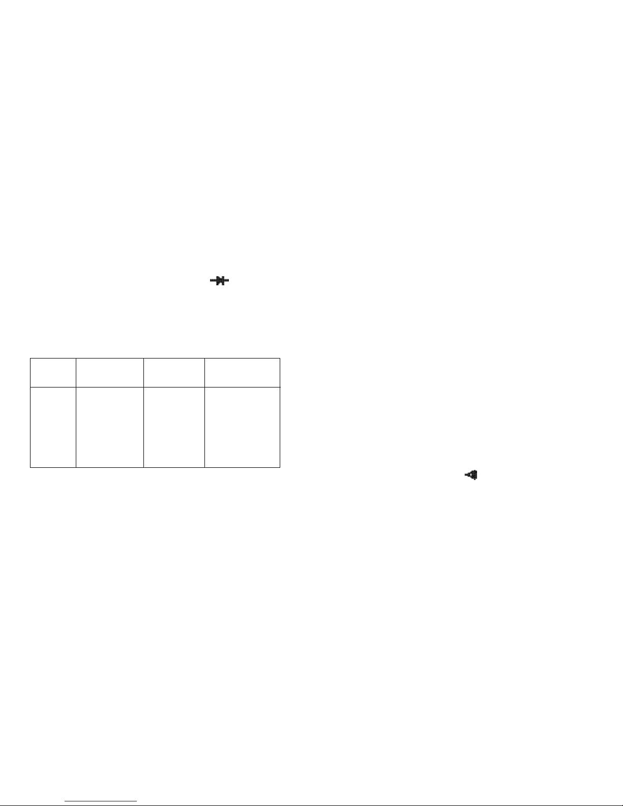
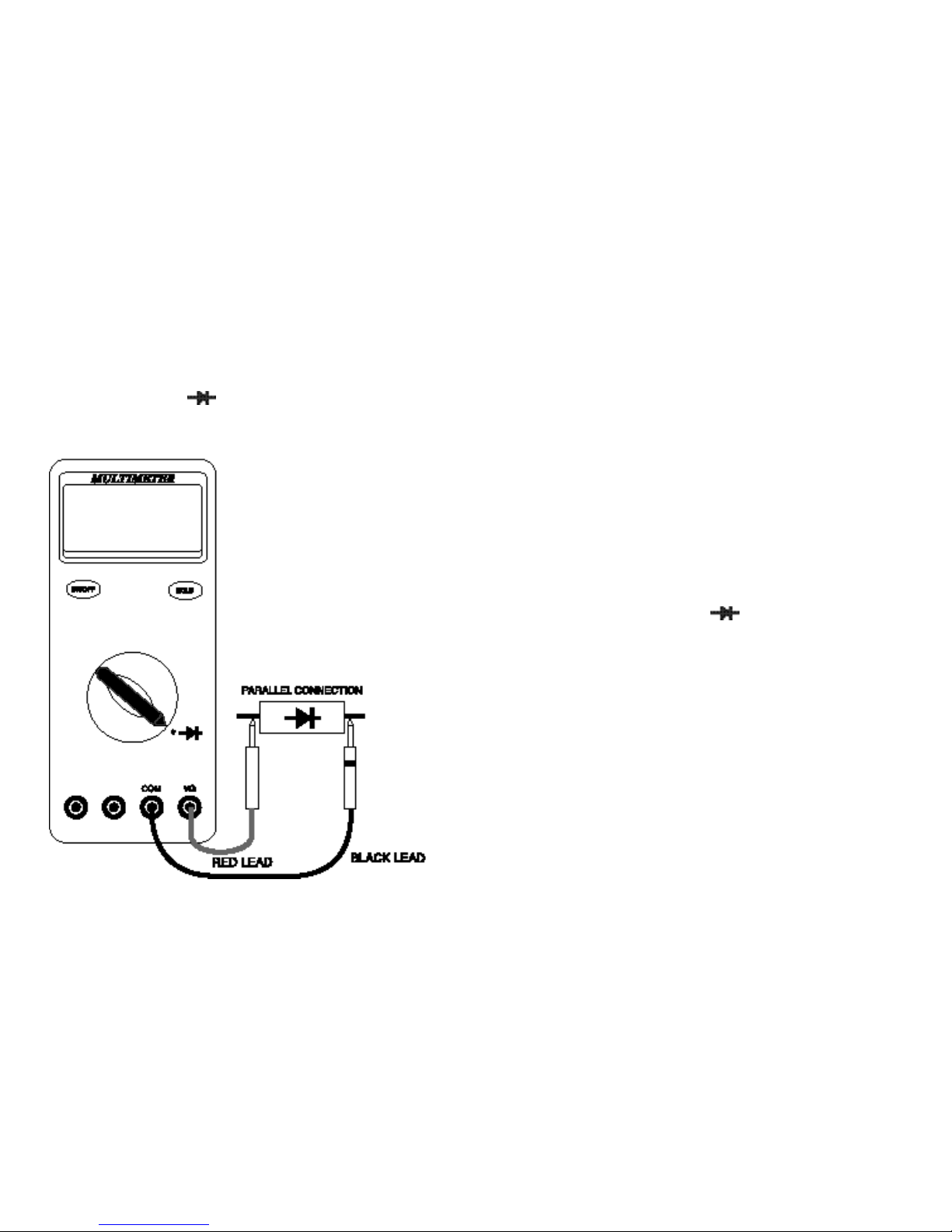
4.3 Diode Test & Microwave Didoes
Diode test lets you check didoes, transistors, and other
semiconductors for opens, short, and normal operation. NEVER
CONNECT THE TEST LEADS TO A SOURCE OF VOLTAGE when
the rotary switch is set to .
• In diode test, drop voltage in the forward direction is displayed when
diode is connected in the forward direction. For a germanium diode,
the typical forward voltage is about 0.4V and in case of a silicon
diode, about 0.6V.
• Judge the semiconductor device as follows:
It the digital reading in one direction shows a value and the reading
in reverse direction shows an overload (
I
...
). the device is good.
If the digital reading is the same in both directions, the device is
probably shorted.
If the display reads
I
. . .
in both directions, the device is probably
open.
4.3.1 Diode Test
Follow these steps to check a diode.
1. Set the Function switch to the “ ” position.
2. Insert the black test lead into the “COM” input terminal and the red
test lead into the “VΩ” input terminal.
3. Touch the red test lead to the Anode (+ side. non-banded end) and
the black test lead to the Cathode (- side. banded end).
4.
If the diode is good, the reading should indicate 0.3V to 0.8V on the
LCD.
5. Reverse the red and black leads on the diode, if the LCD reads
I
...
(the overload sign) the diode is good.
NOTE: A defective diode will read
I
...
( the overload sign) or 0.00
no matter how the test leads are connected.
Page 11
18 19
4.3.2 Microwave Didoes
Most microwave didoes can not be tested by a DMM with a diode test
function. This is because the DMM does not supply enough power to
turn these diode on. We offer an accessory test lead, model TL60, that
boosts the power output so that microwave didoes can be adequately
tested. Consult your distributor for more details.
4.4 Measuring Current (Amps)
CAUTION!
THE CURRENT FUNCTIONS ARE PROTECTED BY A FUSE OF
600 VOLT RATING. TO AVOID DAMAGE TO THE INSTRUMENT,
CURRENT SOURCES HAVING OPEN CIRCUIT VOLTAGES
GREATER THAN 600 VOLTS DC OR AC MUST NOT BE
MEASURED.
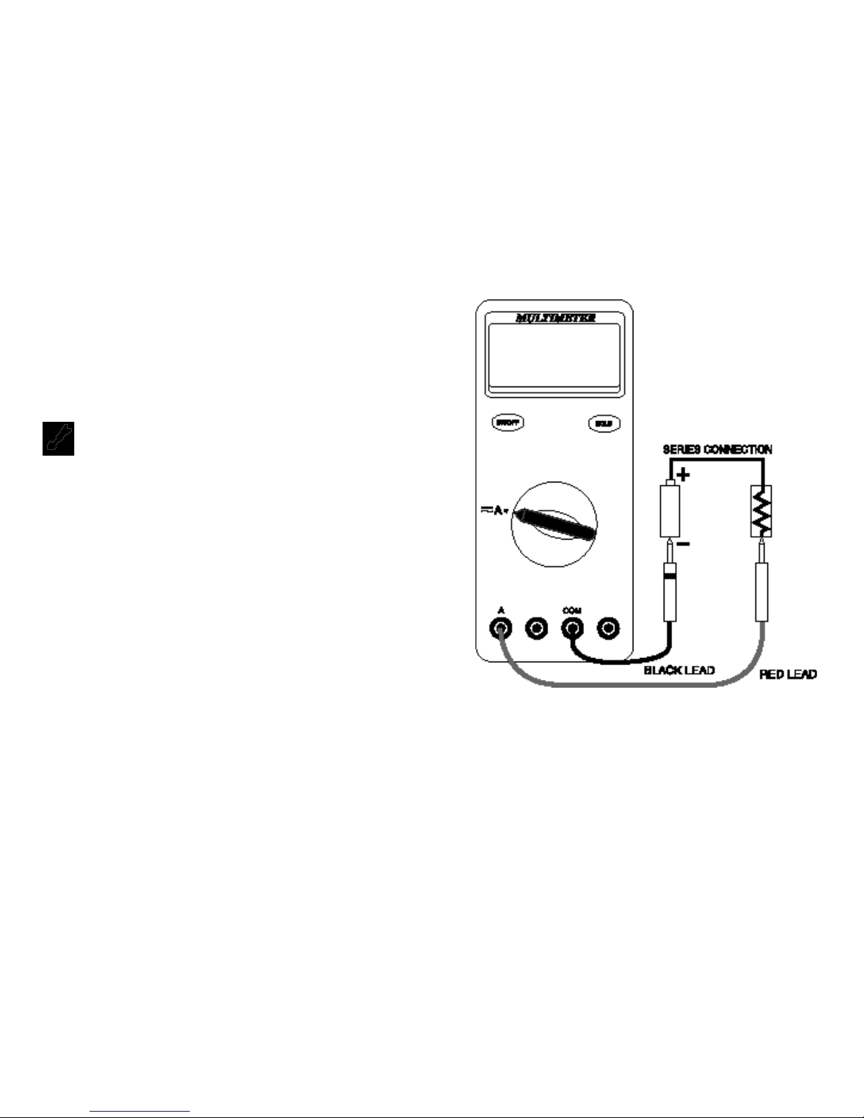
NOTE: When taking current measurements, this Meter must be
connected in SERIES with the circuit (or circuit element)
under test. NEVER CONNECT THE TEST LEADS ACROSS
A VOLTAGE SOURCE while the rotary switch is set to
Amps. This can cause damage to the circuit under test or
this Meter.
• To measure current, you must break the circuit and connect the test
leads to two circuit connection points. The connection must be in
series with the current.
• In alternating current measurement, waveforms other than sine
wave causes error.
Page 12

• When measuring current, the Meter’s internal shunt resistors
develop a voltage across the meter’s terminals called “burden
voltage”. This voltage drop may affect precision circuits or
measurements.
Follow these steps to measure DC (or AC) Amps.
1. Set function and range switch to the desired DC A (or AC A )range.
If you do not know the value of the current to be measured, always
start with the highest range and reduce the setting as required to
obtain a satisfactory reading.
2. Plug the red test lead into the “mAµA” input terminal (if the10A
range is being used, plug the red lead into the “A” input terminal)
and the black lead into the “COM” input terminal of the instrument.
3. Disconnect the power from the circuit to be tested.
4. Connect the test leads in series to the circuit to be tested.
5. Reapply power to the circuit, the measured current will appear on
the display of the instrument.
6. Disconnect power to the circuit before removing the test leads from
the circuit.
20 21
5.1 General Maintenance
WARNING!
REPAIRS OR SERVICING NOT COVERED IN THIS MANUAL
SHOULD ONLY BE PERFORMED BY QUALIFIED PERSONNEL. TO
AVOID ELECTRICAL SHOCK, DO NOT SERVICE UNLESS YOU
ARE QUALIFIED TO DO SO.
Periodically wipe the case with a damp cloth and detergent; do not use
abrasives or solvents. Water, dirt, or contamination in the A or mAµA
input terminals may harm this Meter.
Calibrate this Meter once a year to maintain its performance
specifications.
5.2 Battery Replacement
The Meter uses a 9V battery (NEDA 1604 or IEC 6F22). To replace the
battery, remove the two screws of the battery compartment from the
back of the Meter and lift off the cover of the compartment. Replace
the battery. Reattach the battery compartment to the back of the Meter,
and reinstall the screws.
5. MAINTENANCE AND REPLACEABLE PARTS
Page 13

22 23
5.3 Fuse(s) Test And Replacement
5.3.1 Fuse(s) Test
To test the internal fuses of this Meter:
1. Set the rotary switch to “ ” position.
2. Turn this Meter on.
3. To test F2 (15A, 600v), plug a test lead into the VΩ input terminal
and touch the probe to the A input terminal.
The display should read about 0.000V. If the display reads i. . .
(overload), replace the fuse and test again. If the display reads any
other value, have this Meter serviced.
4 To test F1 (2A, 600V), move the probe from the A input terminal to
the mAµA input terminal.
The display should read 0.5V~0.6V. If the display reads i. . .
(overload), replace the fuse and test again. If the display reads any
other value, have this Meter serviced.
5.3.2 Fuse(s) Replacement
1. Unplug the test leads. Remove the rubber boot from the instrument.
2. Remove the screws in the rear of the instrument and separate the
front and rear housing.
3. Replace the fuses(s) with the same type and size as the one
removed.
4. Snap the front and rear housing back together and reinstall the
screws.
5. Reattach the rubber boot.
NOTE: When servicing the Meter, use only the replaceable parts
specified.
BT1 Battery, 9 Volt
F1 Fuse 2A, 600V RMS
F2 Fuse 15A, 600V RMS
TL1 Test Lead Set
C2Y Rubber Boot (Yellow)
6. ACCESSORIES
Page 14

FUNCTION
RANGE RESOLUTION ACCURACY
REMARKS
VOLTAGE DROP:
200µA 0.1µA
1mV/µA
AC A 2mA 1µA
100mV/µA
(45Hz to 20mA 10µA ± (1.0% + 3 dgts) 10mV/mA
450Hz) 200mA
100µA
1.2mV/mA
2A
1mA
0.28V/A
10A 10mA ± (3.0% + 10 dgts) 0.22V/A
Ohms
200Ω 0.1Ω ± (0.5% + 10 dgts) OPEN CIRCUIT
VOLTAGE
2KΩ 1Ω
20KΩ 10Ω ± (0.5% + 1 dgt) < 1.2V
200KΩ 0.1KΩ
2MΩ 1KΩ
20MΩ 10KΩ ± (1.0% + 2 dgt)
Continuity OPEN CIRCUIT TEST VOLTAGE: < 1.2V
THRESHOLD. Approx. < 150Ω
Diode Check OPEN CIRCUIT TEST VOLTAGE: < 3V
MAX. TEST CURRENT: 1mA
FUNCTION
RANGE RESOLUTION ACCURACY
REMARKS
Input Impedance:
200mV
100µV
DC V 2V 1mV
20V 10mV ± (0.5% + 1 dgt) 10MΩ
200V 0.1V
1000V 1V
200mV 100µV Input Impedance:
AC V 2V
1mV
(45Hz to 20V 10mV ± (0.8% + 3 dgts) 10MΩ
450Hz) 200V 0.1V
750V 1V ± (1.2% + 3 dgts)
VOLTAGE DROP:
200µA 0.1µA
1mV/µA
DC A 2mA 1µA
100mV/µA
20mA 10µA ± (0.8% + 1 dgt) 10mV/mA
200mA 100µA 1.2mV/mA
2A 1mA
0.28V/A
10A 10mA ± (2.0% + 10 dgts) 0.22V/A
24 25
7.1 Specifications
Accuracy is given as ±( [ % of reading ] + [ number of least significant
digits] ) at 18°C to 28°C with relative humidity up to 80%, for a period
of one year after calibration.
NOTE:
DC V. NORMAL MODE REJECTION RATIO: > 46dB at 50Hz or 60Hz
COMMON MODE REJECTION RATIO: > 104dB at dc, 50Hz or 60Hz
AC V. COMMON MODE REJECTION RATIO: > 80dB at dc, to 60Hz
FUSE PROTECTION. µA or mA : 2A 600V FAST fuse
A : 15A 600V FAST fuse
with > 10000A interrupt rating
7. SPECIFICATIONS
Page 15
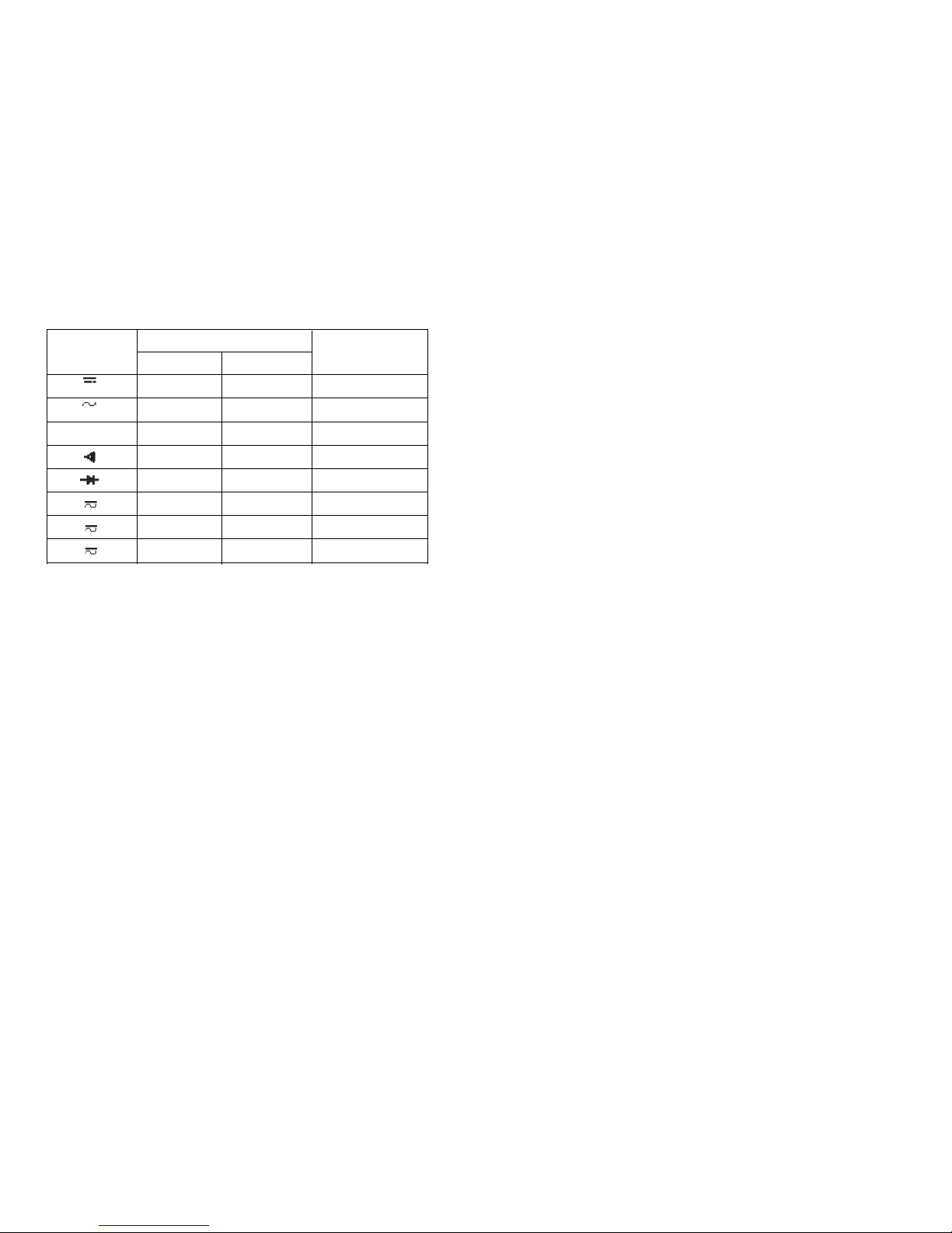
7.2 Maximum Inputs
7.3 General Specifications
Display (LCD)
Digital : Counts – 2000
Updates 3 times/sec
Fuse Protection
mA or µA : 2A 600V HIGH ENERGY/FAST FUSE
A : 15A 600V HIGH ENERGY/FAST FUSE
Storage Temperature : –20°C to 60°C (–4°F to 140°F)
Operating Temperature : 0°C to 45°C (32°F to113°F)
Relative Humidity : 0% to 80% (0°C to 35°C; 32°F to 95°F)
0% to 70% (35°C to 45°C; 95°F to 113°F)
Temperature Coefficient: 0.10 x (Specified Accuracy)/°C
(< 18°C or > 28°C; <64°F or >82°F)
26 27
FUNCTION INPUT TERMINAL MAXIMUM INPUT
RED LEAD BLACK LEAD
VΩ
COM 1000V
VΩ
COM 750V
Ω VΩ COM 600V
VΩ COM 600V
VΩ COM 600V
A A COM 10A/600V
mA mAµA COM 2A/600V
µA mAµA
COM 2A/600V
V
V
Temperature Coefficient: 0.10 x (Specified Accuracy)/°C
(< 18°C or > 28°C; <64°F or >82°F)
Battery Type : 9V, NEDA 1604 or 6F22 or 006P
Battery Life : 350 hrs typical (alkaline)
Size (H x W x L)
Meter Only : 4.0 cm x 8.5 cm x 19.0 cm
With Holster : 5.4cm x 10.3 cm x 20.8 cm
Weight
Meter Only : 380g
With Holster : 655g
Vibration & Shock : Designed to MIL-T-28899 for a Class ll
instrument
Safety Standards
: Designed to both IEC 1010-1 (Overvoltage
Category ll), and the EMC Directive,
UL 1244, CSA C22.2 No. 231
and ISA-DS82
 Loading...