

Page 1

1
PROFESSIONAL WIFI WEATHER STATION
Operation Manual
Model: HP2550
Thank you for purchasing this Professional WIFI Weather Station! This
device provides accurate weather readings and is Wi-Fi capable to stream data
from the weather station to Internet based weather services.
This manual will guide you, step-by-step, through setting up your weather
station and console, and understanding the operation of your weather station.
Use this manual to become familiar with your professional weather station
and save it for future reference.
Page 2

2
1 Table of Contents
1 TABLE OF CONTENTS ............................................................................. 2
2 WARNINGS AND CAUTIONS .................................................................... 5
3 UNPACKING .............................................................................................. 6
4 OVERVIEW ................................................................................................. 7
4.1 DISPLAY CONSOLE .................................................................................. 7
4.2 INDOOR SENSOR: .................................................................................... 7
4.3 OUTDOOR SENSOR: ................................................................................ 8
4.4 OPTIONAL SENSOR ................................................................................. 8
5.SET UP GUIDE ......................................................................................... 10
5.1 PRE INSTALLATION CHECKOUT .............................................................. 10
5.2 SITE SURVEY........................................................................................ 10
5.3 OUTDOOR SENSOR PACKAGE ASSEMBLY............................................... 11
5.3.1 Install U-bolts and metal plate ..................................................... 11
5.3.2 Install wind vane .......................................................................... 12
5.3.3 Install wind speed cups ............................................................... 12
5.3.4 Install the Rain Gauge Funnel .................................................... 13
5.3.5 Install Batteries in sensor package ............................................. 13
5.3.6 Mount assembled outdoor sensor package ................................ 14
5.3.7 Reset Button and Transmitter LED ............................................. 15
5.4 INDOOR SENSOR SET UP ...................................................................... 16
5.5 MULTI-CHANNEL TEMPERATURE AND HUMIDITY SENSOR (OPTIONAL) ....... 17
5.5.1 Install batteries ............................................................................ 17
5.5.2 Sensor Placement ....................................................................... 19
5.6 BEST PRACTICES FOR WIRELESS COMMUNICATION ................................ 20
5.7 CONSOLE DISPLAY ............................................................................... 21
5.7.1 Initial Display Console Set Up ..................................................... 23
5.7.2 Key functions ............................................................................... 24
5.7.3 Main interface icons explain ........................................................ 25
5.8 MULTIPLE CHANNEL SELECTION AND SCROLL MODE .............................. 27
Page 3

3
5.9 HISTORY MODE .................................................................................... 27
5.9.1 View and Reset MAX/MIN ........................................................... 27
5.9.2 History Record Mode .................................................................. 29
5.10 SETTING MODE .................................................................................. 32
5.10.1 Date and Time setting ............................................................... 34
5.10.2 Time Format setting .................................................................. 35
5.10.3 Date Format setting ................................................................... 36
5.10.4 Temperature unit setting ........................................................... 36
5.10.5 Barometric unit .......................................................................... 36
5.10.6 Wind speed unit ........................................................................ 36
5.10.7 Rainfall unit ............................................................................... 36
5.10.8 Solar Rad. Unit .......................................................................... 36
5.10.9 Multi Channel Sensor ................................................................ 36
5.10.10 Backlight setting ...................................................................... 38
5.10.11 Longitude: Latitude setting ...................................................... 39
5.10.12 Barometric display ................................................................... 40
5.10.13 Rainfall season (default: January) .......................................... 40
5.10.14 Storing Interval (1-240minutes Selectable) ............................. 41
5.10.15 Weather Server ....................................................................... 41
5.10.15 .1 Wunderground server setup ........................................ 42
5.10.15.2 Weathercloud server setup ........................................... 48
5.10.16 Wi-Fi scan ............................................................................... 58
5.10.17 Background ............................................................................. 60
5.11 ALARM SETTING MODE ....................................................................... 60
5.12 CALIBRATION MODE ............................................................................ 61
5.13 FACTORY RESET ................................................................................. 66
5.13.1 Re-register indoor transmitter ................................................... 67
5.13.2 Re-register outdoor transmitter ................................................. 67
5.13.3 Automatic Clear Max/Min .......................................................... 67
5.13.4 Reset to Factory ........................................................................ 67
5.13.5 Clear History ............................................................................. 68
5.13.6 Clear Max/Min ........................................................................... 68
5.13.7 Backup data .............................................................................. 68
Page 4

4
5.13.8 About information ...................................................................... 69
6.1BEAUFORT WIND FORCE SCALE ............................................................. 69
6.2WEATHER FORECASTING ....................................................................... 70
6.3 LIGHTNING ALERT .................................................................................. 71
6.4 WEATHER FORECASTING DESCRIPTION AND LIMITATIONS ....................... 71
6.5MOON PHASE ........................................................................................ 72
7. MAINTENANCE ....................................................................................... 74
8. TROUBLESHOOTING GUIDE ................................................................ 75
9. GLOSSARY OF COMMON TERMS ....................................................... 79
10. SPECIFICATIONS ................................................................................. 82
Page 5
5
2 Warnings and Cautions
Warning: Any metal object may attract a lightning strike, including
your weather station mounting pole. Never install the weather station in a
storm.
Warning: If you are mounting the weather station to a house or
structure, consult a licensed electrician for proper grounding. A direct
lightning strike to a metal pole can damage or destroy your home.
Warning: Installing your weather station in a high location may result
in injury or death. Perform as much of the initial check out and operation on
the ground and inside a building or home. Only install the weather station on
a clear, dry, day.
Page 6
6
QT
Item Description
1
Display Console
1
Outdoor Sensor Body with built-in: Thermo-hygrometer / Rain
Gauge / Wind Speed Sensor/ Wind Direction Sensor, Light and UV
sensor, Solar panel
1
Wind speed cups (to be attached to outdoor sensor body)
1
Wind vane (to be attached to outdoor sensor body)
1
Indoor sensor unit
2
U-Bolts for mounting on a pole
4
Threaded nuts for U-Bolts (M5 size)
1
Metal mounting plate to be used with U-Bolts
1
Wrench for M5 bolts
1
AC adapter
1
User manual (this manual)
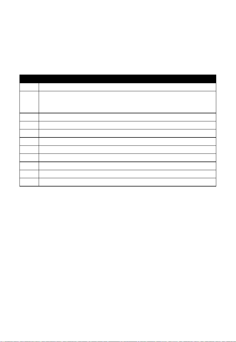
3 Unpacking
Open your weather station box and inspect that the contents are intact
(nothing broken) and complete (nothing missing). Inside you should find the
following:
Table: Package content
If components are missing from the package, or broken, please contact
customer service to resolve the issue.
Note: Batteries for the outdoor sensor package are not included. You will
need 2 AA size batteries, alkaline or Lithium batteries (Lithium
recommended for colder climates).
Note: The console operates using an AC adapter. The included adapter is a
switching-type adapter and can generate a small amount of electrical
interference with the RF reception in the console, when placed too
close to the console. Please keep the console display at least 2 ft. or
0.5 m away from the power adapter to ensure best RF reception from
the outdoor sensor package.
Page 7
7
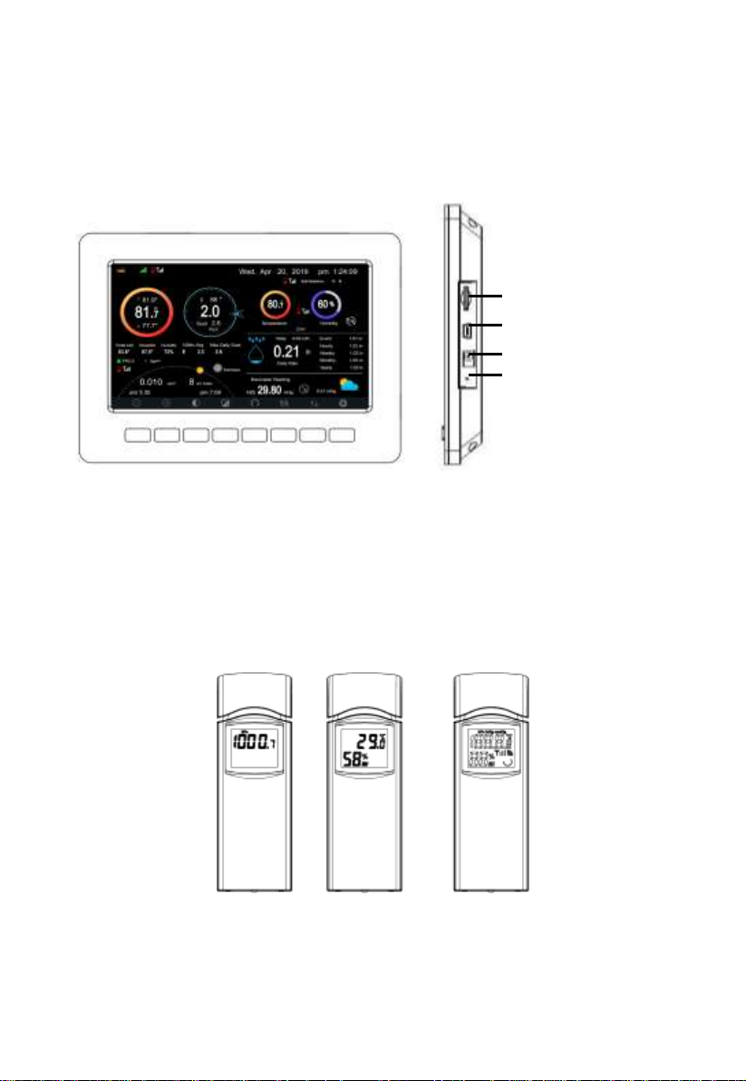
memory card slot
Power jack
Reset
USB port
4 Overview
4.1 Display console
Figure 1: Display console
Note: The USB port in the console of weather station is only for firmware
update, not for data communication (USB cable not included).
You can use a SD card for the firmware update.(SD card not included).
4.2 Indoor sensor:
The indoor sensor will display indoor temperature, humidity and barometric
pressure alternately.
Figure 2: Indoor sensor 2 display variations
Page 8
8
4.3 Outdoor sensor:
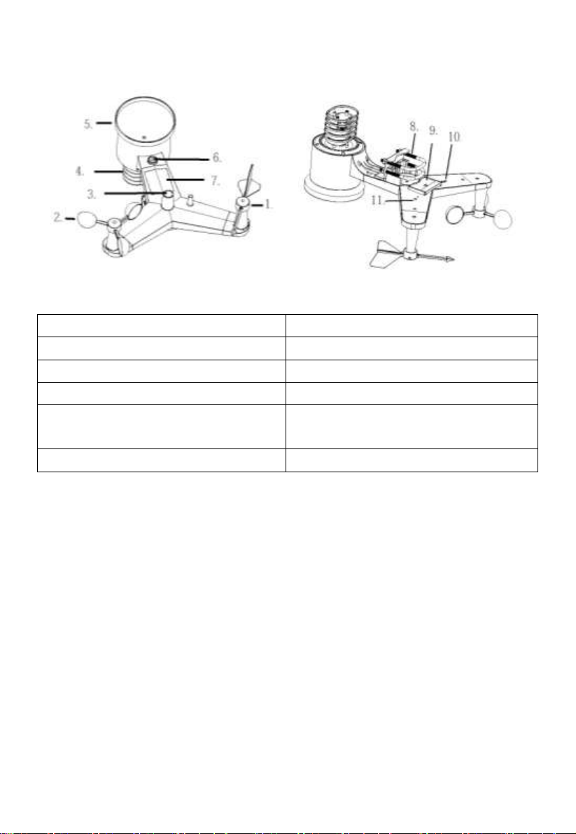
1 Wind vane
7 Solar panel
2 Wind speed cups
8 U-Bolts
3 Light sensor and UV sensor
9 Battery compartment door
4 Thermo- and hygro-meter senor
10 Reset button
5 Rain collector
11 LED (red) to indicate data
transmission
6 Bubble level
Figure 3: Sensor assembly components
Table: Sensor assembly detailed items
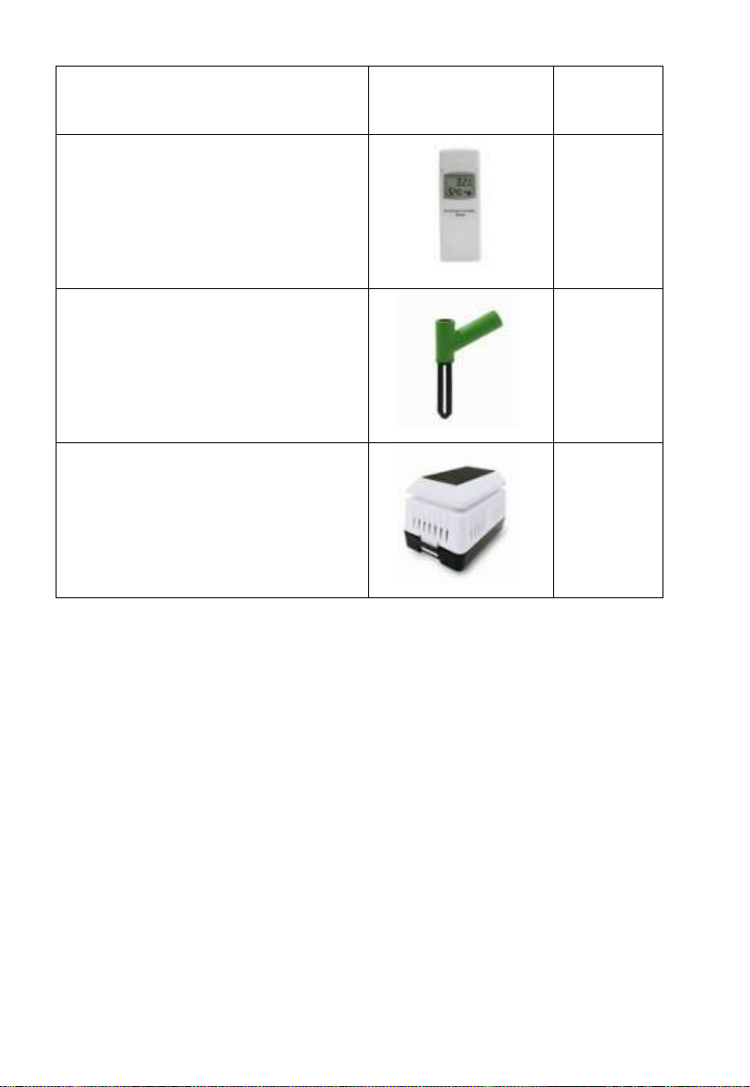
4.4 Optional sensor
The following optional sensors (purchased separately) can be used with
HP2550 console display.
If you have purchase extra sensors, just simple power up, the display console
will receives the data automatically. If sensor not reporting in to console, the
display console will re-search the data after one hour or restart the console to
search the data. Please refer to the sensor manual (provided separately with
sensor) for details.
This table shows the maximum number of each type of sensor that can be
worked with console display
Page 9
9
Sensor
Image
Maximum
Number
WH31 Multi-channel temperature
and humidity sensor*,**
8
WH51 Soil moisture sensor*
1
WH41 PM2.5 air quality sensor*,**
1
*Console display just show the current data, the history data save in the SD
card.
**WU website doesn’t support. Ecowitt.net can support these sensor data
upload.
Page 10

10
5.Set up Guide
5.1 Pre Installation Checkout
To complete assembly you will need a Philips screwdriver (size PH0) and a
wrench (size M5; included in package).
Before installing the weather station on the place of operation, we recommend
placing the weather station at a temporary location with easy access for one
week. This will let you check all functions, ensure proper operation, and get
familiar with the weather station and its calibration procedures. During this
time, you can also test the wireless range between the main unit and the
integrated wireless sensor.
Attention:
Follow suggested order for battery installation (outdoor sensor first,
console second)
Ensure batteries are installed with correct polarity (+/-)
Do not mix old and new batteries
Do not use rechargeable batteries
If outdoor temperature may go below 32F or 0C for prolonged periods,
Lithium based batteries are suggested over alkaline type batteries for the
outdoor sensor array
5.2 Site Survey
Perform a site survey before installing the weather station. Consider the
following:
1. Avoid radiant heat transfer from buildings and structures. In general,
install the sensor array at least 5’ or 1.52m from any building,
structure, ground, or roof top.
2. Avoid wind and rain obstructions. The rule of thumb is to install the
sensor array at least four times the distance of the height of the tallest
Page 11
11
obstruction. For example, if the building is 20’ or 6.10m tall and the
mounting pole is 6’ or 1.83m tall, install the sensor array 4 x (20 – 6)’
= 56’ or 4 x (6.1-1.83)=17.08m away.
3. Installing the weather station over sprinkler systems or other
unnatural vegetation may affect temperature and humidity readings.
We suggest mounting the sensor array over natural vegetation.
4. Radio Interference. Computers, radios, televisions and other sources
can interfere with radio communications between the sensor array
and console. Please take this into consideration when choosing
console or mounting locations. Make sure your display console is at
least five feet or 1.52 meter away from any electronic device to avoid
interference.
5.3 Outdoor Sensor Package Assembly
5.3.1 Install U-bolts and metal plate
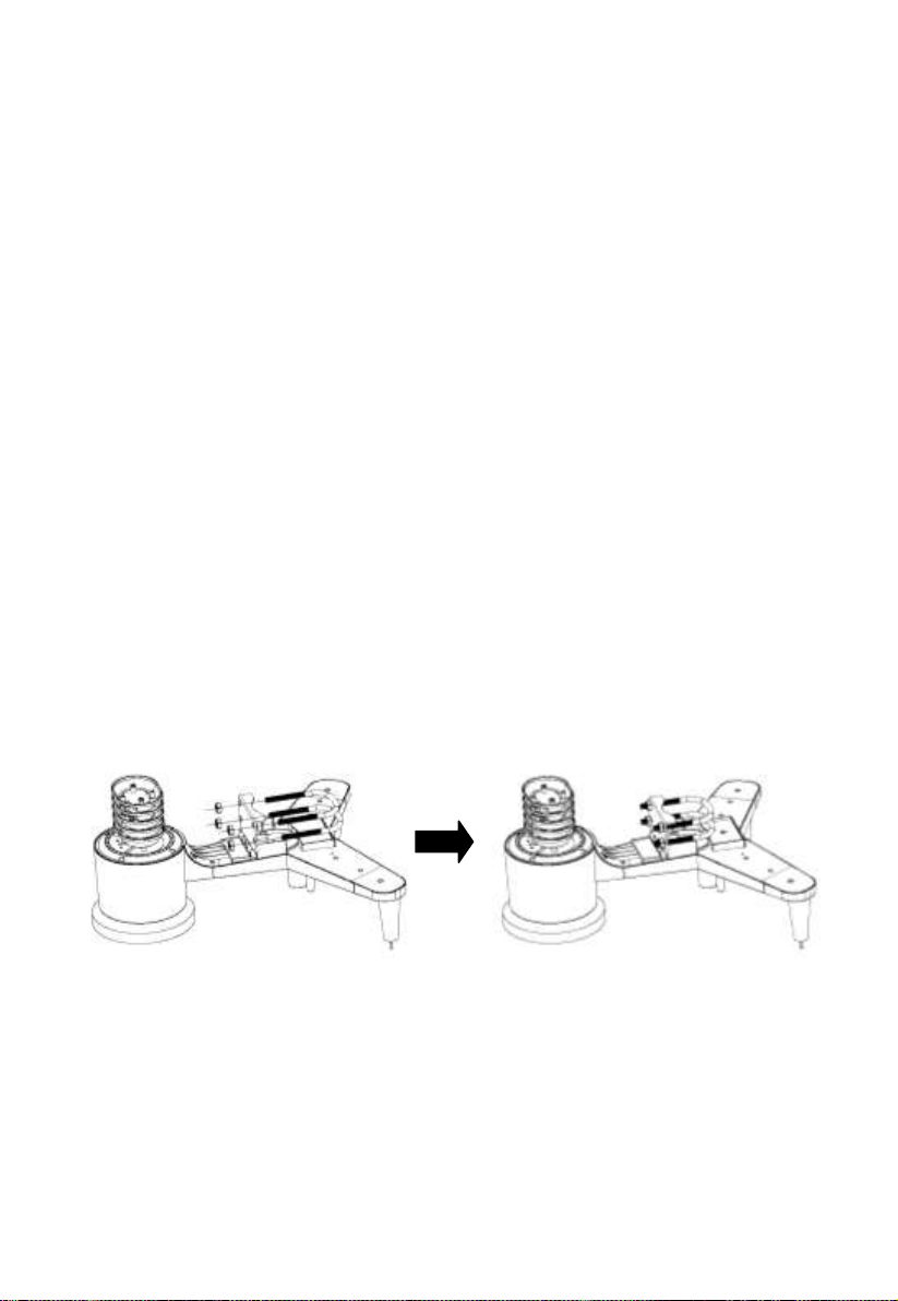
Slide the U-bolts into the metal plate on the underside of the integrated
wireless sensor and screw the nuts from the other side so that the bar on which
the integrated wireless sensor is placed can be inserted into this hole.
Figure 4: U-Bolt installation
The plate and U-Bolts are not yet needed at this stage but doing this now may
help avoid damaging wind vane and wind speed cups later on. Handling of the
sensor package with wind vane and speed cups installed to install these bolts
is more difficult and more likely to lead to damage.
Page 12
12
5.3.2 Install wind vane
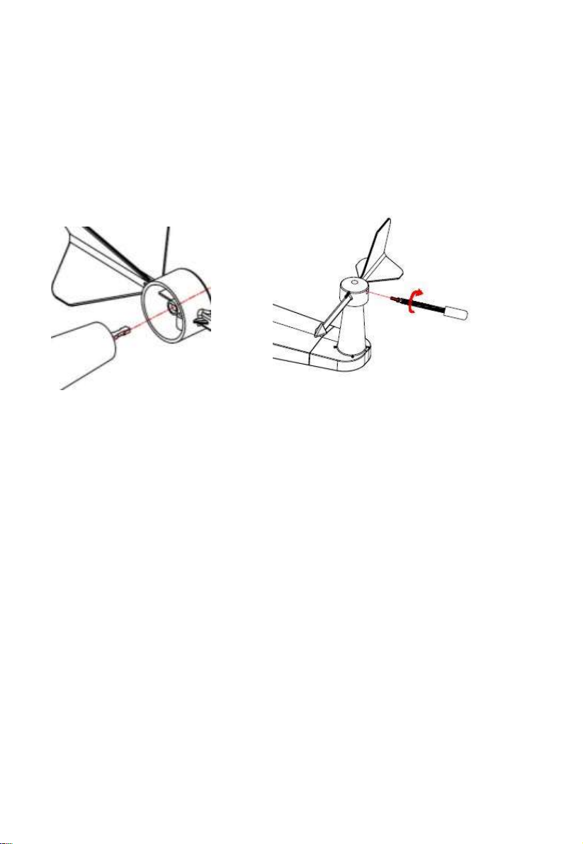
Push the wind vane onto the shaft on the top side of the sensor package, until
it goes no further, tighten the set screw, with a Philips screwdriver (size PH0).
Make sure the wind vane can rotate freely. The wind vane’s movement has a
small amount of friction, which is helpful in providing steady wind direction
measurements.
Figure 5: Wind vane installation diagram
The wind direction section on the main unit display shows the letters N
(North), E (East), S (South) and W (West). The integrated wireless
sensor must be oriented so that the arrow marked “North” on the top
of the wireless sensor is pointing north. If the integrated wireless
sensor is oriented incorrectly, wind direction measurement will be
inaccurate.
5.3.3 Install wind speed cups
Push the wind speed cup assembly onto the shaft on the top side of the sensor
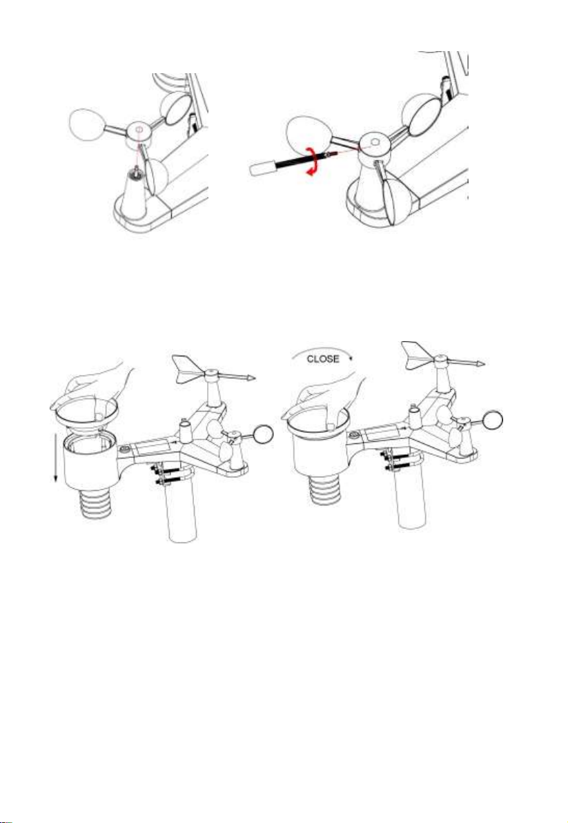
package, Tighten the set screw, with a Philips screwdriver (size PH0). Make
sure the cup assembly can rotate freely. There should be no noticeable friction
when it is turning.
Page 13
13
Figure 6: Wind speed cup installation diagram
5.3.4 Install the Rain Gauge Funnel
Rotate clockwise to attach the funnel to the sensor array.
Figure 7: Rain Gauge Funnel installation diagram
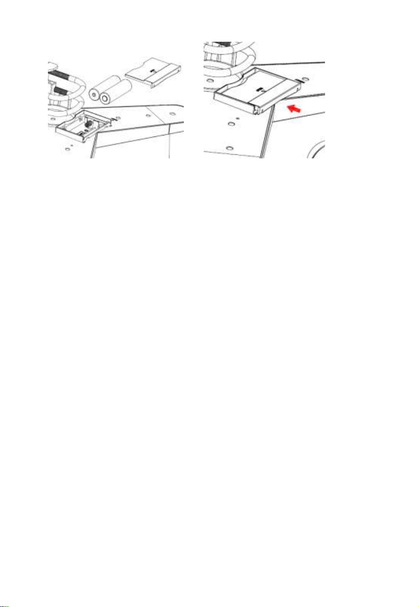
5.3.5 Install Batteries in sensor package
Open the battery compartment and insert 2 AA batteries in the battery
compartment. The LED indicator on the back of the sensor package will turn
on for 4 seconds and then flash once every 16 seconds indicating sensor data
transmission.
Page 14
14
Figure 8: Battery installation diagram
Note: If LED does not light up or is on permanently, make sure the battery
is inserted the correct way and inserted fully, starting over if
necessary. Do not install the batteries backwards as it may
permanently damage the outdoor sensor.
Note: We recommend Lithium batteries for cold weather climates, but
alkaline batteries are sufficient for most climates. Rechargeable
batteries have lower voltages and should never be used.
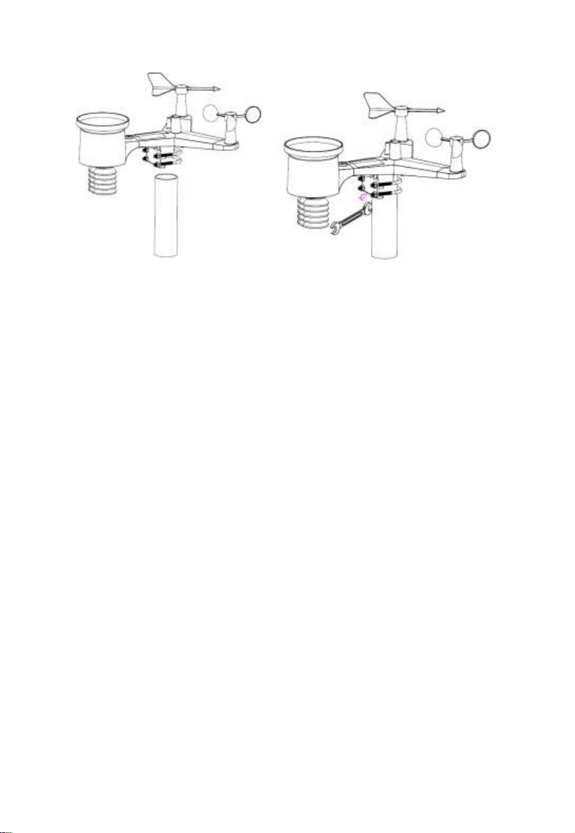
5.3.6 Mount assembled outdoor sensor package
Install the integrated wireless sensor in an open space, away from obstacles
such as other buildings, trees, etc. that prevent free wind flow, to ensure
undistorted measurements of individual weather elements. Point the part with
the vane and propeller north for correct wind direction measurement. Place
the integrated wireless sensor onto the stand (not included) at a minimum
distance of 1.5 metres from the ground to prevent the measured values being
affected by the ground surface and tighten the bolts. Use the spirit level on the
top of the integrated wireless sensor to ensure that it is level. Tighten the
U-bolt nuts.
Page 15
15
Figure 9: Sensor package mounting diagram
.
Note: If you tested the full assembly indoors and then came back here for
instructions and mounted to sensor package outdoor you may want to
make some further adjustments on the console. The transportation
from indoor to outdoor and handling of the sensor is likely to have
“tripped” the rainfall sensing bucket one or more times and
consequently the console may have registered rainfall that did not
really exist. You can use console functions to clear this from history.
Doing so is also important to avoid false registration of these readings
with weather services..
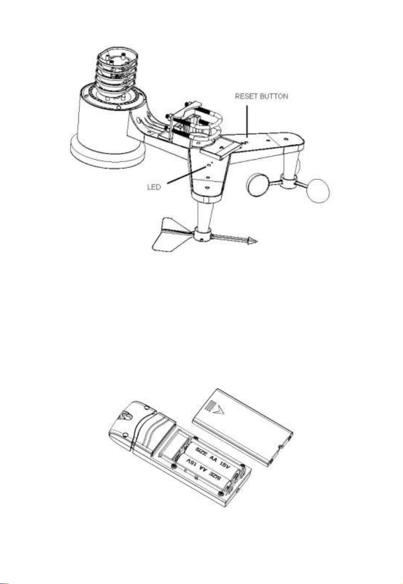
5.3.7 Reset Button and Transmitter LED
In the event the sensor array is not transmitting, reset the sensor array.
Using a bent-open paperclip, press and hold the RESET BUTTON (see
Figure 0) to affect a reset: the LED turns on while the RESET button is
depressed, and you can now let go. The LED should then resume as normal,
flashing approximately once every 16 seconds.
Page 16
16
Figure 10: Reset button and Transmitter LED location
5.4 Indoor Sensor Set Up
Note: To avoid permanent damage, please take note of the battery polarity
before inserting the batteries.
Remove the battery door on the back of the sensor. Insert two AA batteries.
Figure 11: Indoor sensor battery installation
Page 17
17
5.5 Multi-channel temperature and humidity sensor
(Optional)
The HP2550 supports up to 8 additional thermo-hygrometer sensors (WH31),
which can be viewed on the display tablet and Internet.
Note: Do not use rechargeable batteries. We recommend fresh alkaline
batteries for outdoor temperature ranges between -10 °C and 60 °C and fresh
lithium batteries for outdoor temperature ranges between -40 °C and -10 °C.
5.5.1 Install batteries
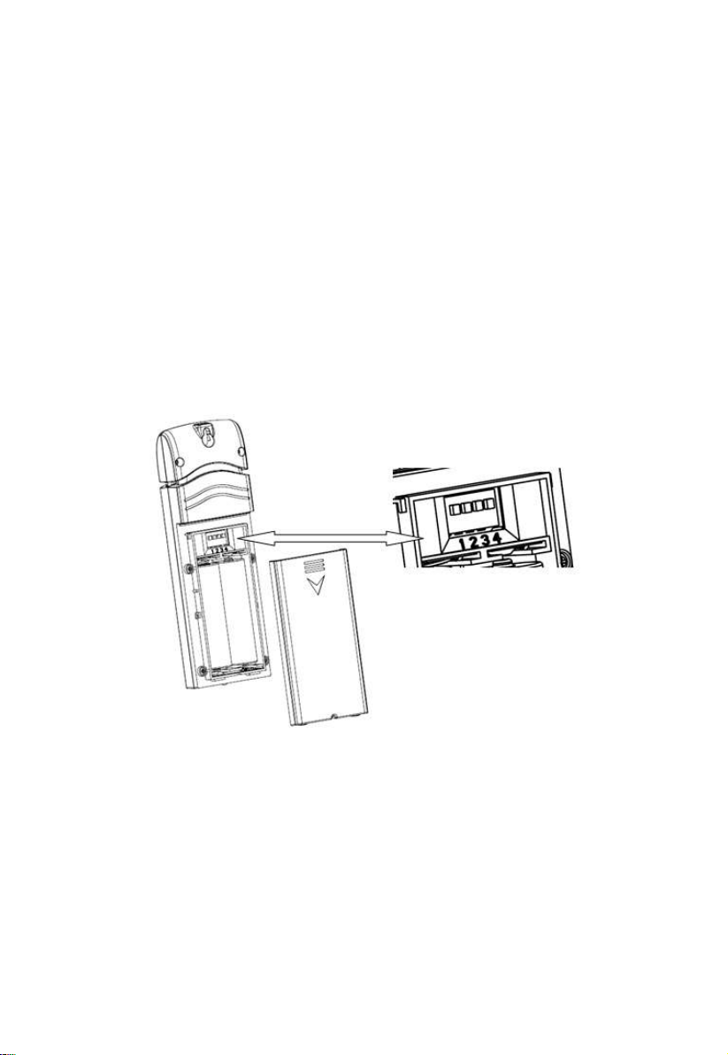
1. Remove the battery door on the back of the transmitter(s) by sliding
down the battery door, as shown in Figure 2 .
Figure 12: Battery installation for Multi-channel sensor
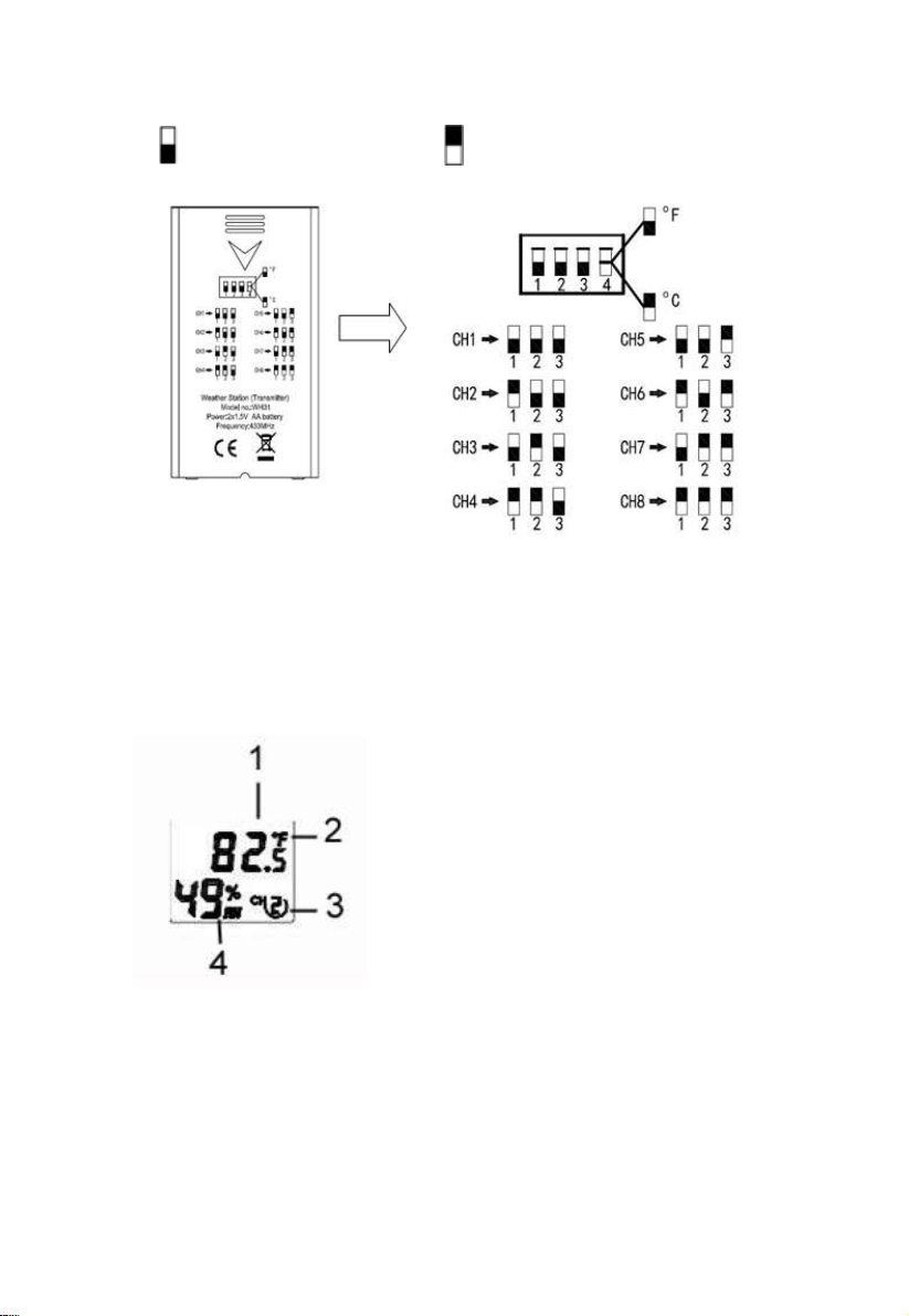
2. BEFORE inserting the batteries, locate the dip switches on the
inside cover of the lid of the transmitter.
3. Channel Number: The device supports up to eight sensors. To set
each channel number change Dip Switches 1, 2 and 3, as
referenced in Figure .
4. Temperature Units of Measure: To change the transmitter display
units of measure (°F vs. °C), change Dip Switch 4, as referenced in
Page 18
18
Figure .
Switch in down position. Switch in up position.
Figure 13: Dip Switch diagram
5. Insert two AA batteries.
6. Verify the correct channel number (CH) and temperature units of
measure (°F vs. °C) are on the display, as shown in
7.
8. Figure .
(1) temperature
(2) temperature units (°F vs. °C)
(3) channel number
(4) relative humidity
Figure 14: sensor LCD display
9. Close the battery door.
Page 19
19
Repeat for the additional remote transmitters, verifying each remote is on a
different channel.
5.5.2 Sensor Placement
The best mounting location for the indoor sensor is in a location that never
receives direct sunlight, not even through windows. Also, do not install in a
location where a nearby radiant heat source (radiator, heaters, etc.) will affect
it. Direct sunlight and radiant heat sources will result in inaccurate
temperature readings.
The sensor is meant to provide indoor conditions for display on the console,
but if you would rather have a second source for outdoor conditions instead,
you can mount this unit outside. Recommend to mount the unit under cover
(eve or awning or similar).
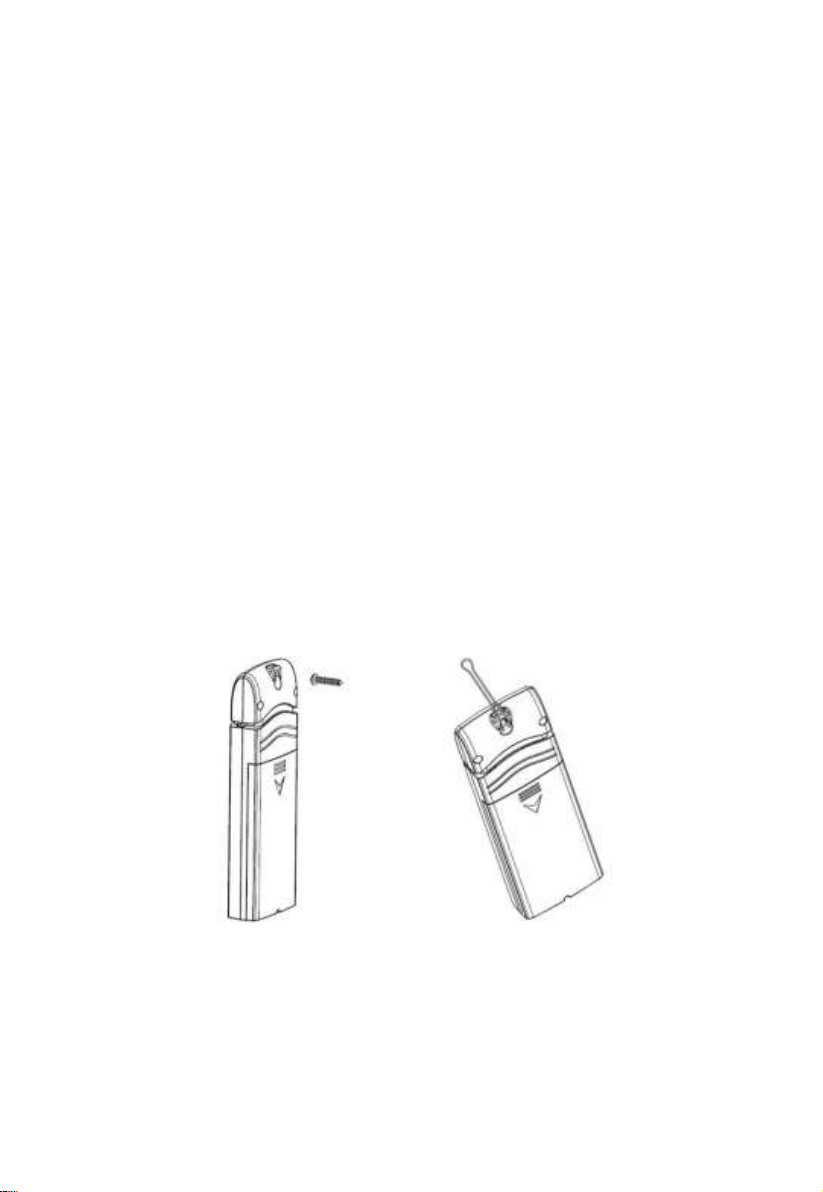
To mount or hang the unit on a wall or wood beam:
Use a screw or nail to affix the remote sensor to the wall, as shown on the
left side of Figure 1, or
Hang the remote sensor using a string, as shown in right side of Figure 1
Figure 15: Indoor sensor mounting
Note: Make sure the sensor is mounted vertically and not lying down on a
flat surface. This will insure optimum reception.
Page 20

20
5.6 Best Practices for Wireless Communication
Wireless (RF) communication is susceptible to interference, distance, walls
and metal barriers. We recommend the following best practices for trouble
free wireless communication between both sensor packages and the console:
Indoor sensor placement: The sensor will have the longest reach for its
signal when mounted or hung vertically. Avoid laying it down on a flat
surface.
Electro-Magnetic Interference (EMI). Keep the console several feet
away from computer monitors and TVs.
Radio Frequency Interference (RFI). If you have other devices
operating on the same frequency band as your indoor and/or outdoor
sensors and experience intermittent communication between sensor
package and console, try turning off these other devices for
troubleshooting purposes. You may need to relocate the transmitters or
receivers to avoid the interference and establish reliable communication.
The frequencies used by the sensors are one of (depending on your
location): 433, 868, or 915 MHz (915 MHz for United States).
Line of Sight Rating. This device is rated at 300 feet line of sight (under
ideal circumstances; no interference, barriers or walls), but in most
real-world scenarios, including a wall or two, you will be able to go about
100 feet.
Metal Barriers. Radio frequency will not pass through metal barriers
such as aluminum siding or metal wall framing. If you have such metal
barriers and experience communication problems, you must change the
placement of sensor package and or console.
The following table shows different transmission media and expected signal
strength reductions. Each “wall” or obstruction decreases the transmission
range by the factor shown below.
Page 21
21
Medium
RF Signal Strength Reduction
Glass (untreated)
5-15%
Plastics
10-15%
Wood
10-40%
Brick
10-40%
Concrete
40-80%
Metal
90-100%
Table: RF Signal Strength reduction
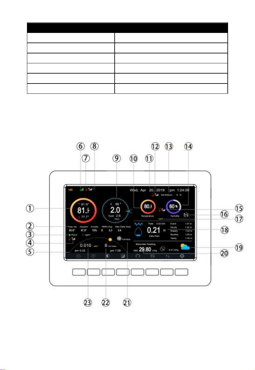
5.7 Console Display
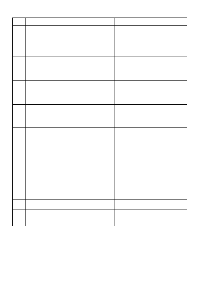
See 6 to help you identify elements of the console’s display screen.
Figure 16: Display Console Screen Layout
Page 22
22
No
Description
No
Description
1
Outdoor temperature
13
Soil moisture(optional sensor)
2
Outdoor Feels Like/Dew
point/Humidity/10Min. Average
Wind Direction/Max Daily Gust
14
Indoor humidity
3
PM2.5 concentration(optional
sensor)
15
RF signal bar for multi-channel
temperature and humidity
sensor(optional sensor)
4
RF signal bar for PM2.5
sensor(optional sensor)
16
Multi-channel temperature and
humidity sensor cycle display
mode icon(optional sensor)
5
Sunrise / Sunset Time
17
Multi-channel temperature and
humidity sensor channel
number (optional sensor)
6
Wi-Fi signal bar
18
Rain fall
Daily/Event/Hourly/Weekly/
Monthly/Yearly
7
Low battery power indicator for
each sensor
19
Weather forecast
8
RF signal bar for outdoor sensor
array
20
ABS/REL Barometer
9
Wind direction/Wind speed/Gust
21
Moon Phase
10
Indoor temperature
22
UV
11
Date and time
23
Solar Radiation
12
RF signal bar for soil moisture
sensor(optional sensor)
Table: Display console detailed items
Page 23
23
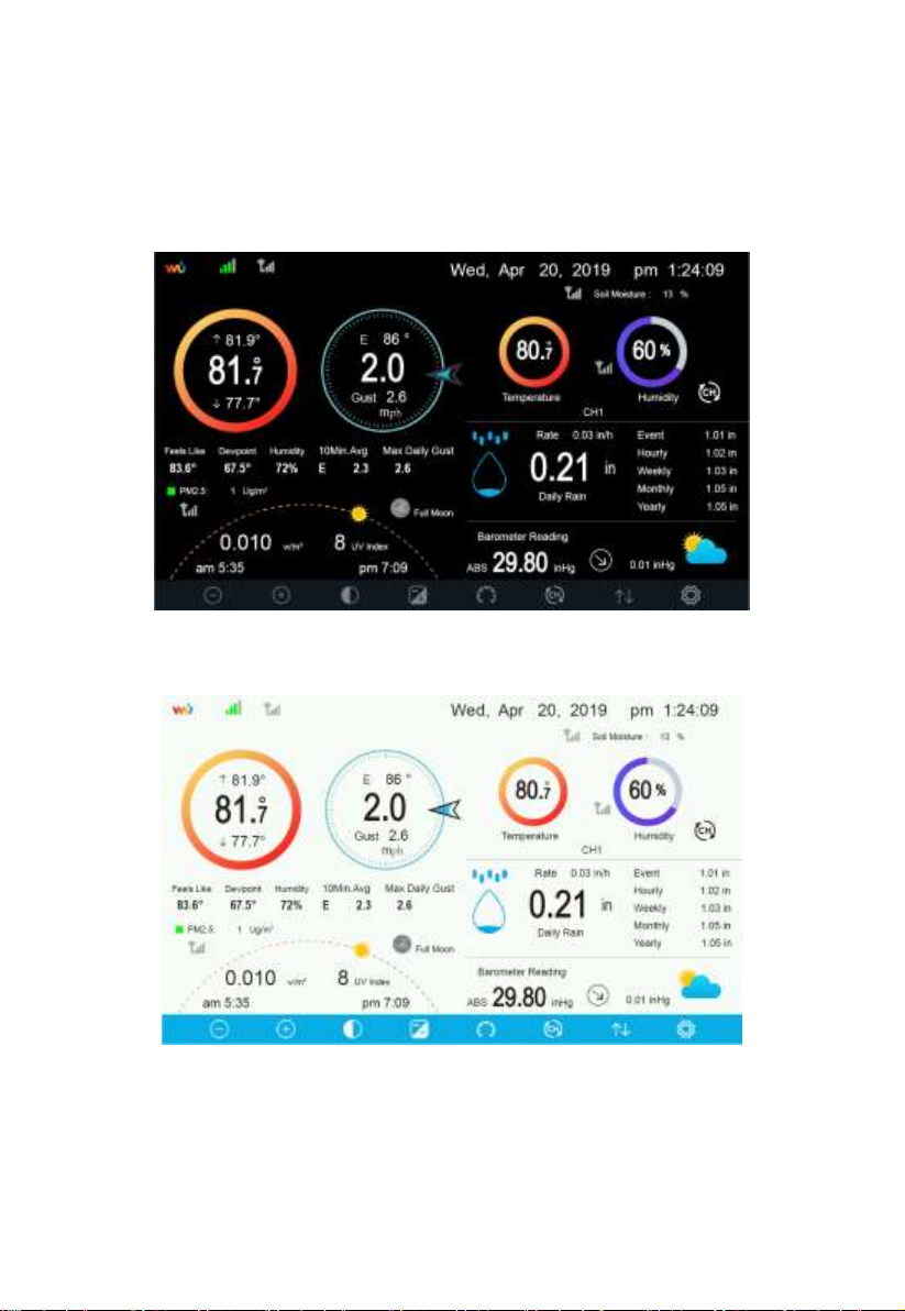
5.7.1 Initial Display Console Set Up
Immediately after power up (inserting power adapter), the unit will turn on the
display, and the unit will start to look for reception of the indoor and outdoor
sensor data. This may take up to 3 minutes.
Dark Background Display
Light Background Display
Note: Sunrise/sunset time display will only work properly when GEO
location has been set up correctly. GEO setup can be carried out under setup
menu.
Page 24
24
Icon
Description
Brightness control key
Press this key to decrease the brightness
Brightness control key
Press this key to enhance the brightness
Backlight on/off key
Press this key to on/off the backlight
Background key
Press this key to choose between dark background display and light
background display
Pressure display key
Press this key to choose the display between Absolute pressure and
Relative pressure.
Channel key
Press this key to Shift the display between indoor temp & humidity,
Multiple Channel temp& humidity and scroll automatically mode
History key
Press this key once to view Max/Min record and twice to enter
History mode.
Setting key
Press this key to enter Setting Mode
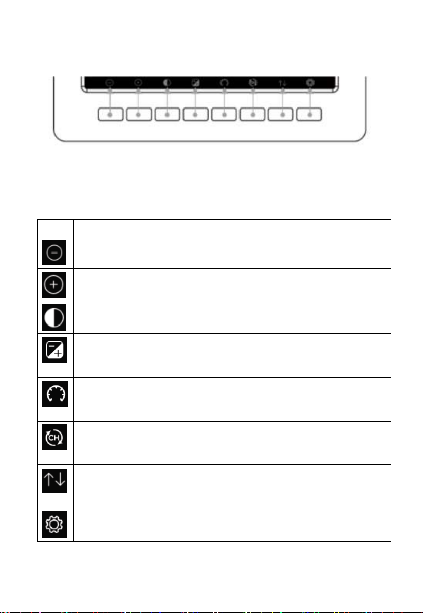
5.7.2 Key functions
Figure 17: Buttons around the display
There is a set of eight keys on the bottom of the display console. The
following tables briefly explains the function of these keys.
Table: Console buttons
Page 25
25
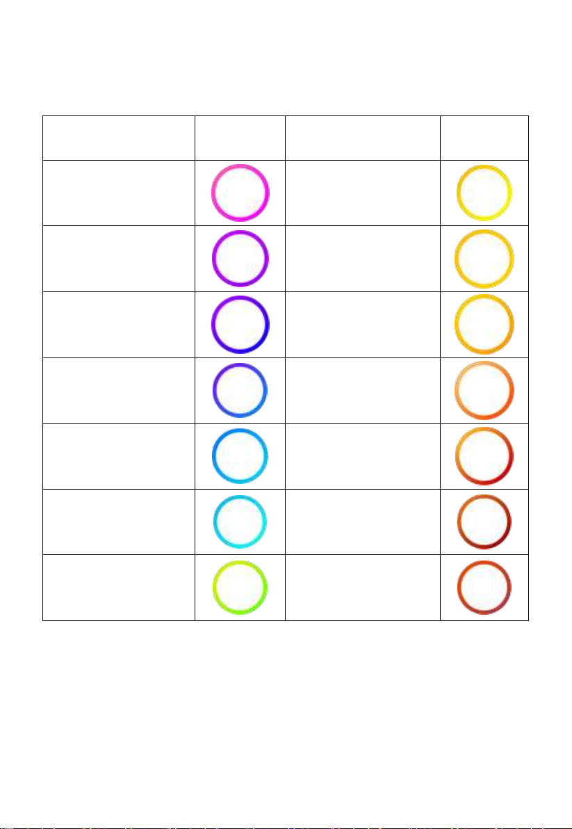
5.7.3 Main interface icons explain
Temperature Range
(degF)
Color Ring
Temperature Range
(degF)
Color Ring
< -10
50-60
-10 to 0
60-70
0 to 10
70-80
10-20
80-90
20-30
90-100
30-40
100-110
40-50
> 110
5.7.3.1 Temperature Icon
Page 26
26
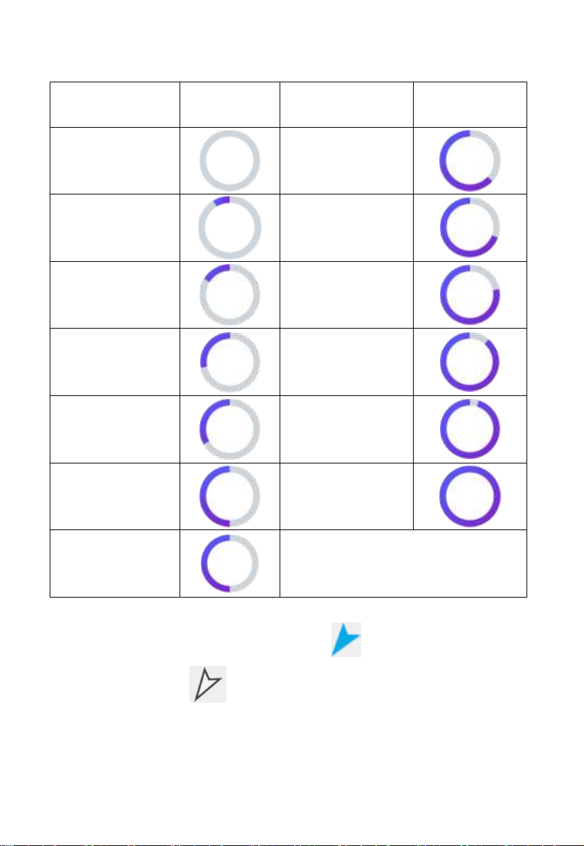
5.7.3.2 Humidity Icon
Humidity Range
(%)
Color Ring
Humidity Range
(%)
Color Ring
0%, No signal or
dashes
50 to 60
1 to 10
60 to 70
10 to 20
70 to 80
20 to 30
80 to 90
30 to 40
90 to 99
40 to 50
100%
50 to 60
5.7.3.3 Current wind direction indication , 10-minute average wind
direction indication .
Page 27
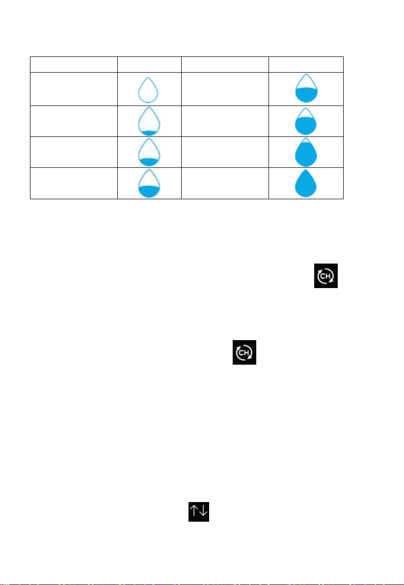
27
Hourly Rain (in)
Icon
Hourly Rain (in)
Color Ring
0.0
0.6 to 0.8
0 to 0.2
0.8 to 1
0.2 to 0.4
1 to 1.2
0.4 to 0.6
1.2 to 1.4
5.7.3.4 Hourly Rainfall Icon
5.8 Multiple Channel Selection and Scroll Mode
Multi-channel sensor is an optional sensor, not included in the package. If you
have multiple wireless sensors, while in normal mode, press the key to
toggle display in sequence of indoor, ch1, ch2….ch8, scroll display. Please
note if only CH2 is received, it will skip CH1, and toggle only between indoor
and already learned sensors.
While in Scroll display mode, the scroll icon will be displayed next to
the indoor humidity, and will scroll every 5 seconds.
Note: For multi channel sensor, only the current data of each sensor can be
viewed on the console, and no history data will be saved or uploaded to any
weather servers.
5.9 History Mode
5.9.1 View and Reset MAX/MIN
While in normal display, press the key once to view and reset
minimum and maximums.
Page 28
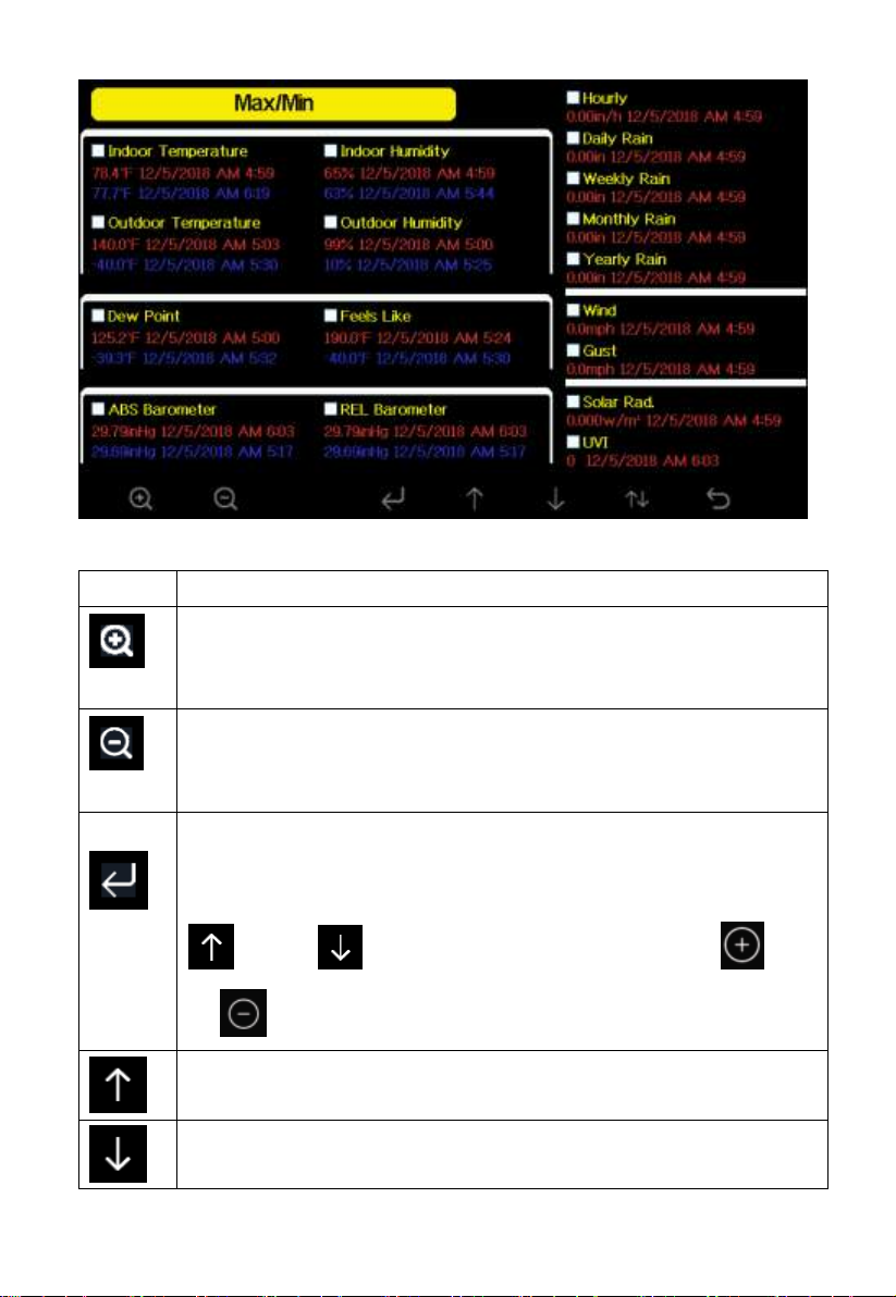
28
Icon
Description
Selection key
Press this key to select the weather MAX/MIN record which
need to clear
Selection key
Press this key to select the weather MAX/MIN record which
need to clear
Enter key
While the desired weather MAX/MIN record selected , press this
key to popup Message Box ”Clear the Max/Min record?”. Press
key or key to select YES or NO. Press the key
or key to confirm the selection.
Up arrow key
Press this key to change the activated option field
Down arrow key
Press this key to change the activated option field
Figure 18: Max/Min Screen
Page 29
29
History key
Press this key to select History data display.
Return key
Press this key to return to normal display mode
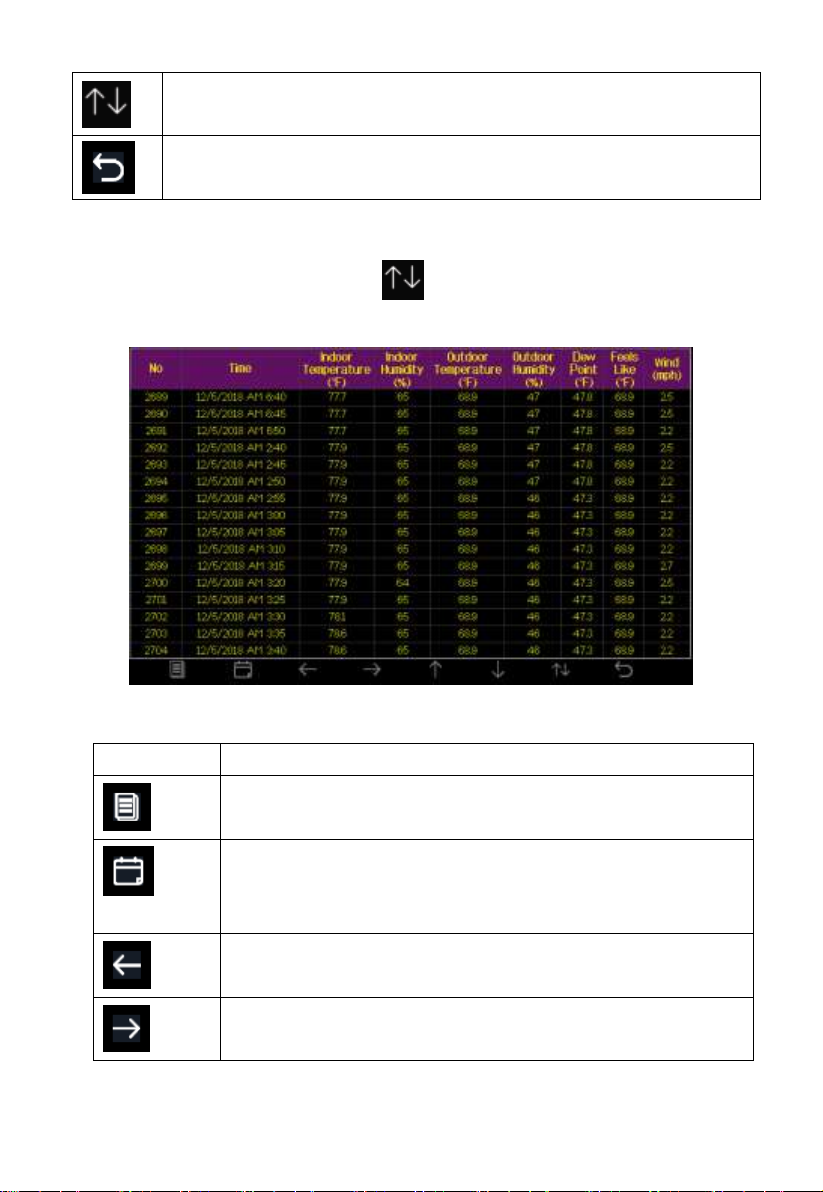
Icon
Description
File Select key
Press this key to clear all history record
Page Select key
Press this key to enter particular page of the history data.
Each page contains 16sets data.
Scroll left key
Press this key to view the left of the scrollable area.
Scroll right key
Press this key to view the right of the scrollable area.
5.9.2 History Record Mode
While in normal display, press the key twice to enter History Record
Mode.
Figure 19: History record Screen
Page 30
30
Page up key
Press this key to scroll up the page you are viewing
Page down key
Press this key to scroll down the page you are viewing
History key
Press this key to select the Max/Min record or History.
Return key
Press this key to return to previous mode
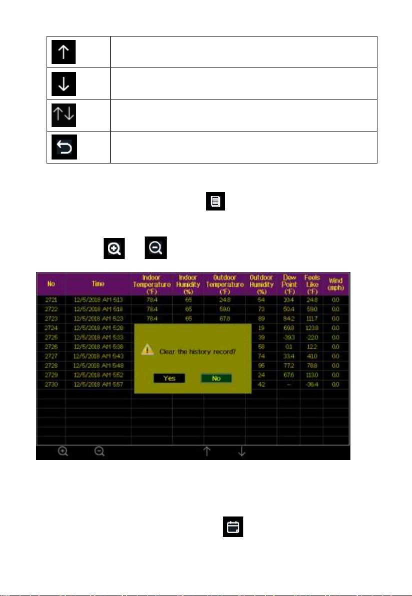
5.9.2.1 Clear the history record
While in History Record Mode, press key to popup the Message Box:
“Clear the history record?” Press “Yes” to clear all history records saved on
console. Press or key to return to History record Mode.
Figure 20: Clear History Record Screen
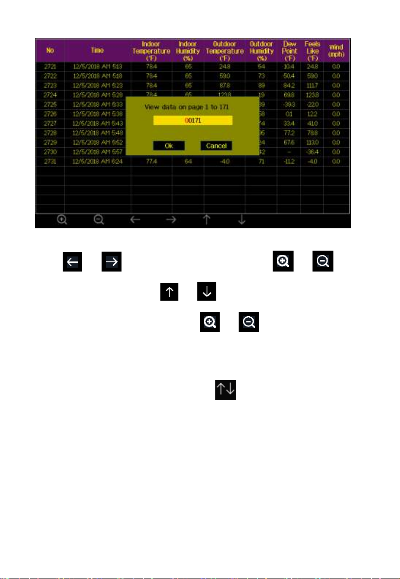
5.9.2.2 View a specific page of history
While in History Record Mode, press the key to enter the page
selection mode:
Page 31
31
Figure 21: view a specific page of history Screen
Press or to select a digit in a number, press or key
to change the number. Press or to change the activated option
field, toggle OK or Cancel then press or key to confirm.
5.9.2.3 View Graph
While in History Record Mode, press the key once to enter Graph
Mode.
Page 32

32
Figure 22: Graph Screen
Press to shift the data display of 12/24/48/72H. Press to view
the graph of the following data:
Indoor outdoor temperature
Dew Point and Feels like
Indoor outdoor humidity
Wind speed and Gust
Wind Direction
UVI
Solar radiation
Rainfall hourly and daily
Barometer (REL & ABS)
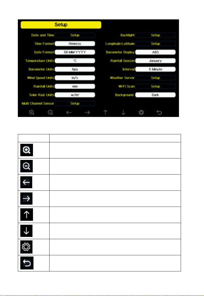
5.10 Setting Mode
While in normal display, press the key to enter Setting Mode. You can
select the below sub-mode by pressing the key
Page 33
33
Icon
Description
Select key
Press this key to select the unit or scrolls the value
Select key
Press this key to select the unit or scrolls the value.
Left key
Press this key to select the set value.
Right key
Press this key to select the set value.
Up arrow key
Press this key to change the activated option field
Down arrow key
Press this key to change the activated option field
Set key
Press this key to select the Setting sub-Mode
Return key
Press this key to return to previous mode
Figure 23: Setup Menu Screen
Page 34
34
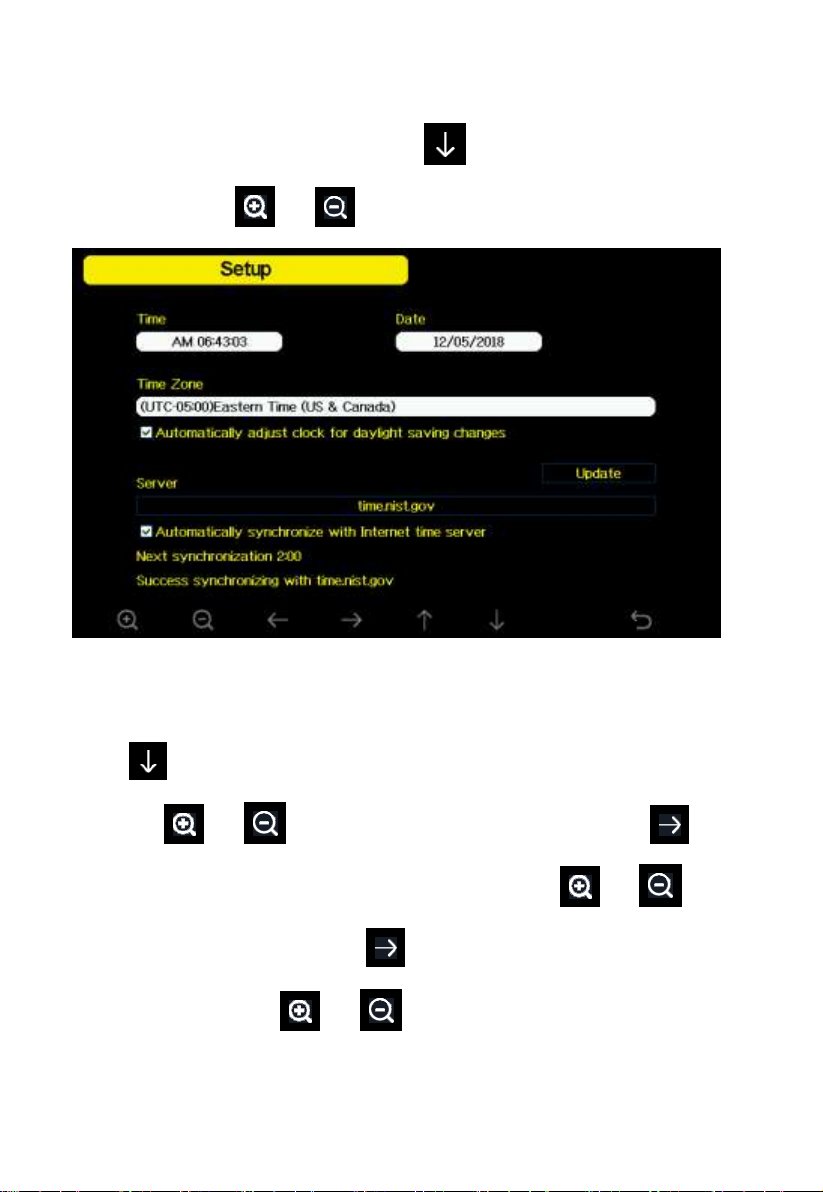
5.10.1 Date and Time setting
While in Menu Setting Mode, press key to select Date and Time
Setup field, press or key to enter Date and Time Setup mode:
Figure 24: Time and date Setup Screen
1) Time setting (hour/minute/second)
Press key to select time setting field, and the hour digit will turn red,
press the or key to change the hour setting. Press to set
the minute, the minute digit will turn red, press the or key to
change the minute setting. Press to set the second, and the second digit
will turn red, press the or key to change the second setting
2) Date setting
Page 35
35
Press key to select Date setting field, the day digit on focus turns red,
press the or key to change the day setting. Press to set the
month, then month digit focused will turn red, press the or key
to change the month setting. Press to set the year, the year digit on
focus will turn red, press the or key to change the year setting
3) Time zone setting
Press key to select Time zone setting field, press the or
key to change the time zone setting. Press key to select Update field,
press the or key to update the time immediately.
4) Automatically synchronize with internet time server
The time server is time.nist.gov. Press the or key to tick”
Automatically synchronize with internet time server” and press” update” to
synchronize with time server immediately. Console time will be updated at
2:01am automatically when internet access is possible.
5.10.2 Time Format setting
Press to change the time format between hour: minute: second
(h:mm:ss), hour: minute: second AM (h:mm:ss AM) and AM hour: minute:
second (AM h:mm:ss).
Page 36
36
5.10.3 Date Format setting
Press to change the time format between DD-MM–YYYY,
YYYY-MM- DD and MM-DD-YYYY
5.10.4 Temperature unit setting
Press to change the temperature units of measure between °F and °C.
5.10.5 Barometric unit
Press to change the temperature units of measure between
inHg, mmHg and hpa
5.10.6 Wind speed unit
Press to change the wind speed units of measure between mph, bft
(Beaufort scale), ft/s, m/s, km/h and knot.
5.10.7 Rainfall unit
Press to change the rainfall units of measure between in and mm
5.10.8 Solar Rad. Unit
Press to change the solar radiation units of measure between W/m^2,
lux and fc.
5.10.9 Multi Channel Sensor
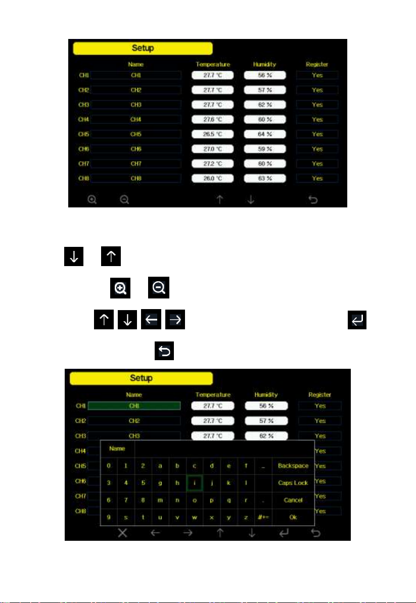
In Multi channel sensor Setup Screen, you can rename the sensor or register
the sensor again while the sensor lost connection to console display.
Page 37
37
Figure 25: Multi channel sensor Setup Screen
Press or key to select Name setting field, the name on focus turns
green, press the or key to pop up the keyboard to enter the sensor
name. Press to scroll to the character and press to
select the character. Press to return to the setup page.
Figure 26: rename the sensor Screen
Page 38
38
Press or key to select Register setting field, press the or
key to register the selected sensor
5.10.10 Backlight setting
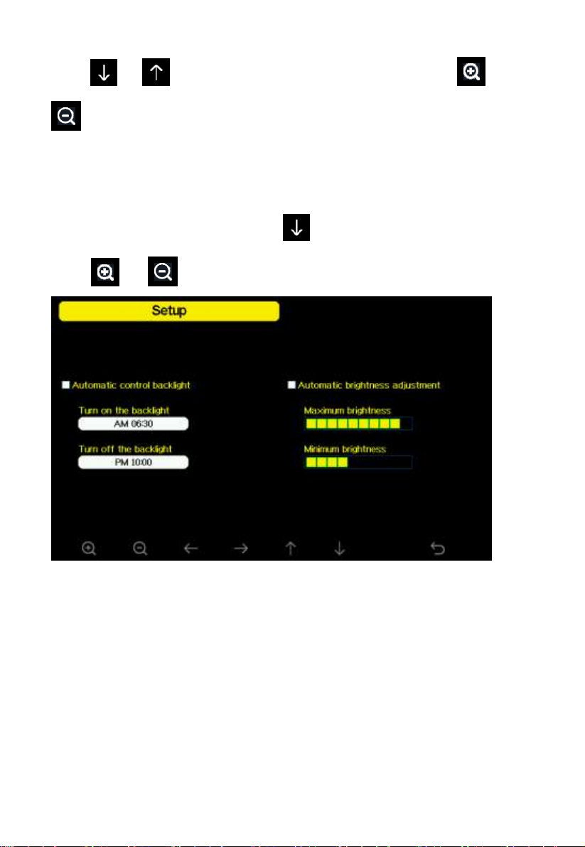
While in Menu Setting Mode, press key to select Backlight Setup field,
press or key to enter backlight Setup mode:
Figure 27: Backlight Setting Screen
Automatic control backlight: select this option, the backlight will auto turn
on and off according the set time
Turn on the backlight: set the time of turning on backlight
Turn off the backlight: set the time of turning off backlight
Automatic brightness adjustment: select this option, the brightness will
change according to the light intensity measured from outdoor sensor
Maximum brightness: set the maximum brightness while it is the highest
light intensity
Page 39
39
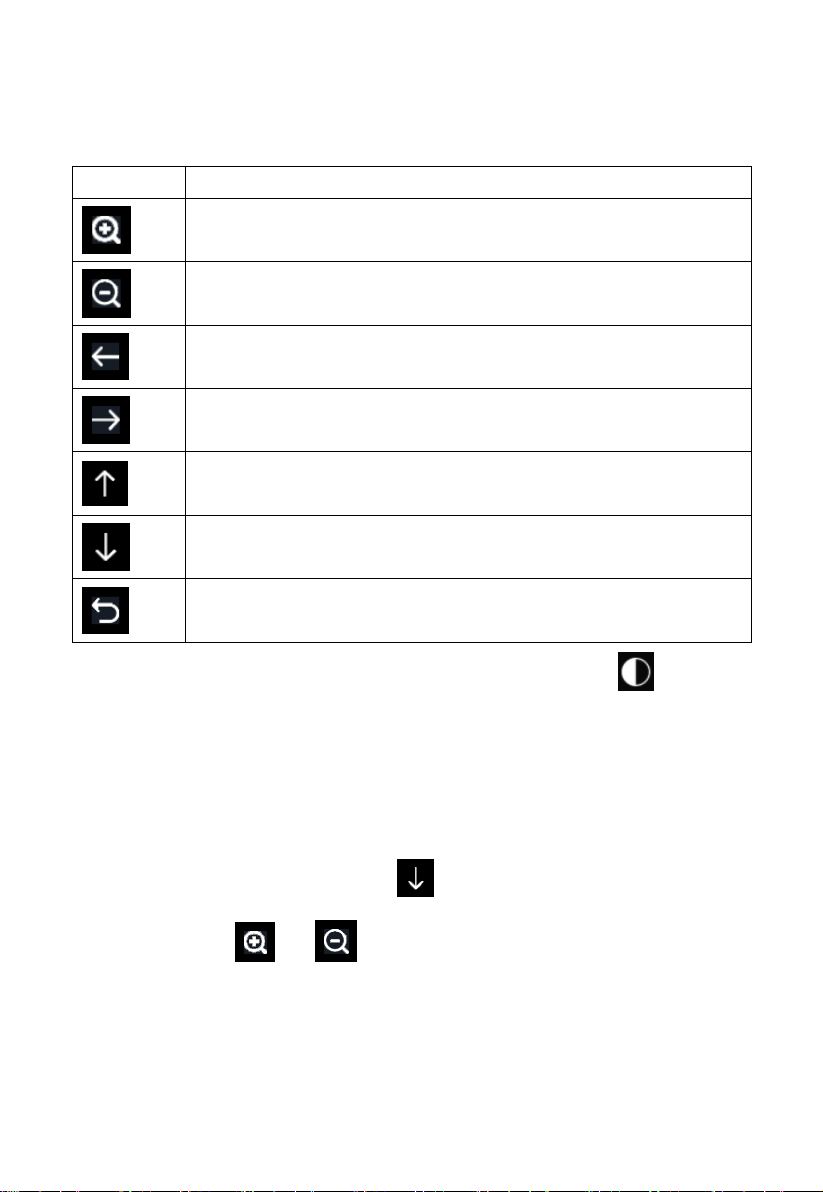
Icon
Description
Select key
Press this key to select the unit or scrolls the value
Select key
Press this key to select the unit or scrolls the value.
Left key
Press this key to select the set value.
Right key
Press this key to select the set value.
Up arrow key
Press this key to change the activated option field
Down arrow key
Press this key to change the activated option field
Return key
Press this key to return to previous mode
Minimum brightness: set the minimum brightness while it is the weakest
light intensity
If the auto backlight turn-on time has been set, you can press key to
turn off the backlight within the turn on time. Backlight will turn on again
automatically at next turn on time. You can press any key to turn on the
backlight for 60s within the turn off time
5.10.11 Longitude: Latitude setting
While in Menu Setting Mode, press key to select Longitude: Latitude
Setup field, press or key to enter Longitude Latitude Setup
mode:
Page 40
40
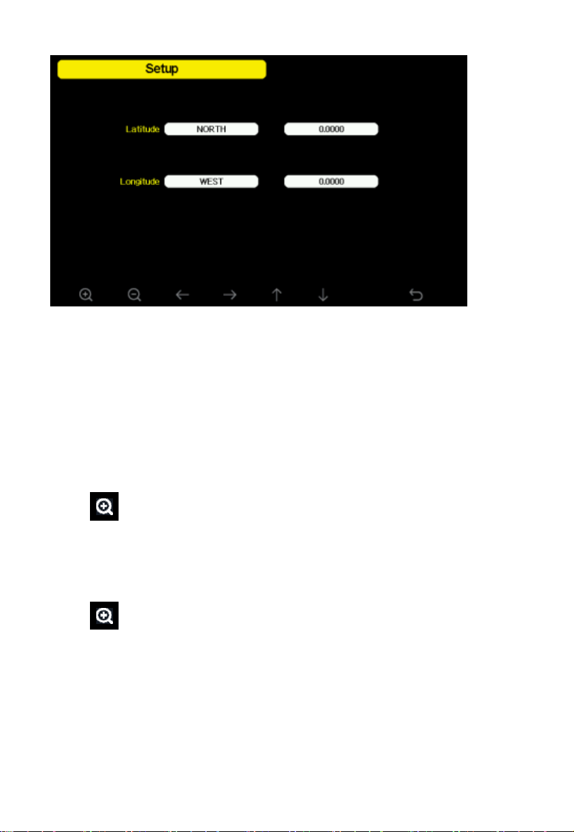
Figure 28: Longitude and Latitude Setting Screen
The sunrise/sunset times will be calculating automatically base on the
Longitude and Latitude. Your location GEO info can be found on mobile
compass page. Two digits after decimal should be enough for this feature to
be working correctly.
5.10.12 Barometric display
Press to change the barometer display between REL (relative pressure)
and ABS (absolute pressure)
5.10.13 Rainfall season (default: January)
Press to change the beginning of the rainfall yearly season month. The
default is January. Rainfall season influence the annual rainfall maximum,
minimum and total value. When one month was selected, the annual rainfall
and annual max/min rainfall were zero clearing at 0:00 of the first day of the
selected month.
Page 41
41
Service
Website
Description
Ecowitt
Weather
https://www.ecowitt.net
Ecowitt is a new weather server
that can host a bunch of sensors
that other services don’t
support.
Weather
Underground
https://www.wunderground.
com
Weather Underground is a free
weather hosting service that
allows you to send and view
your weather station data
real-time, view graphs and
gauges, import text data for
more detailed analysis and use
iPhone, iPad and Android
applications available at
Wunderground.com. Weather
Underground is a subsidiary of
The Weather Channel and IBM.
WOW
http://wow.metoffice.gov.
uk/
WOW is a UK based weather
observation website.
Weather
Cloud
https://weathercloud.net
Weathercloud is a real-time
weather social network formed
by observers from around the
world.
Customized
Website
Supports uploading to your
customized website, if the
website has the same
protocol with Wunderground
or Ecowitt
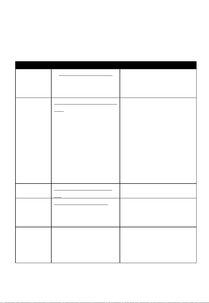
5.10.14 Storing Interval (1-240minutes Selectable)
5.10.15 Weather Server
Your console is capable of sending your sensor data to select internet-based
weather services. The supported services are shown in the table below:
Table: Supported weather services
Page 42
42
Note: If you are testing the setup with the outdoor sensor package nearby
and indoor, you may want to consider connecting to Wi-Fi, but not yet
configuring any of the weather services. The reason is that while indoor the
temperatures and humidity recorded by the outdoor sensor, and as reported
to the weather service(s) will reflect indoor conditions, and not outdoor
conditions. Therefore, they will be incorrect. Furthermore, the rainfall
bucket may be tripped during handling, causing rain to register while it may
not actually have been raining. One way to prevent this is to follow all
instructions, except to use an incorrect password, on purpose! Then, after
final outdoor installation, come back and change the password after clearing
console history. That will start uploading to the services with a clean slate.
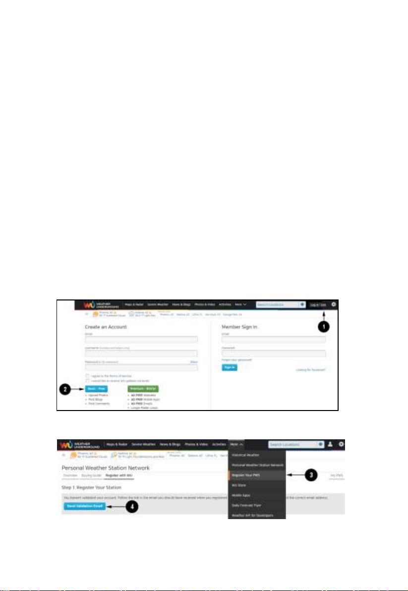
5.10.15 .1 Wunderground server setup
1) Get the station ID and key/password
① Visit Wunderground.com and select the Join link (1) at the top of the
page and select the Free (2) sign up option.
② Select More | Register Your PWS (3)
Page 43
43
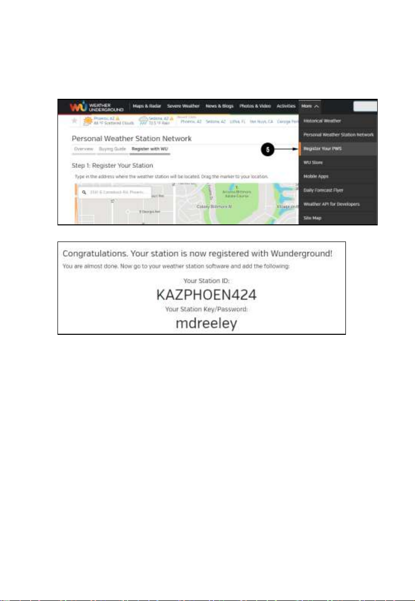
③ Click Send Validation Email (4). Respond to the validation email from
Wunderground.com (it may take a few minutes).
④ Select More | Register Your PWS (5) again. This time you will be
asked details about your weather station. Go ahead and fill out the form
After completing the weather station, you will see something like this:
Your station ID will have the form: KSSCCCC###, where K is for USA
station (I for international), SS is your state, CCCC is an abbreviation for
your city and ### is the station number in that city. In the example above,
you see station 424 in the state of Arizona (AZ) in the United States (K).
⑤ Take note of the station ID and key/password and enter it in the Weather
Server:
Page 44
44
scroll value
up
scroll value
down
Scroll field
up
Scroll field
down
return to
Setup
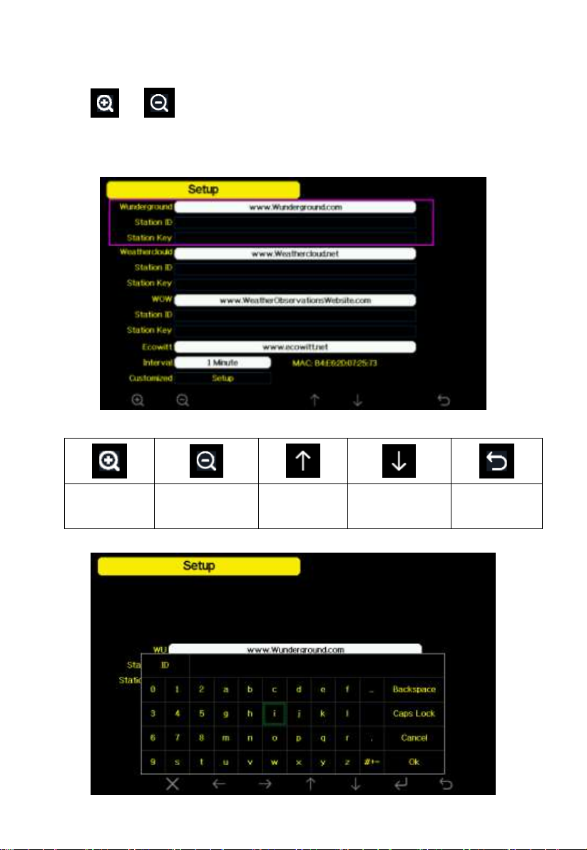
2) Registration on console display
Press or key to enter Weather Server set up mode. The device
can be configured to send real-time data to wunderground.com®. Enter the
Station ID and Password obtained from Wunderground.com.
Figure 29: WU Server setup screen
Page 45
45
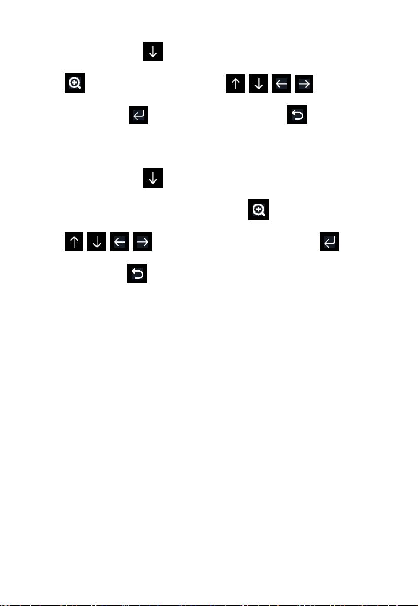
Set Station ID: Press to highlight the Station ID. Enter your station ID.
Press to display the keyboard. Press to scroll to the
character and press to select the character. Press to return to the
setup page.
Set Station Key: Press to highlight the station key. Enter your password
obtained from according weather server. Press to display the keyboard.
Press to scroll to the character and press to select
the character. Press to return to the setup page.
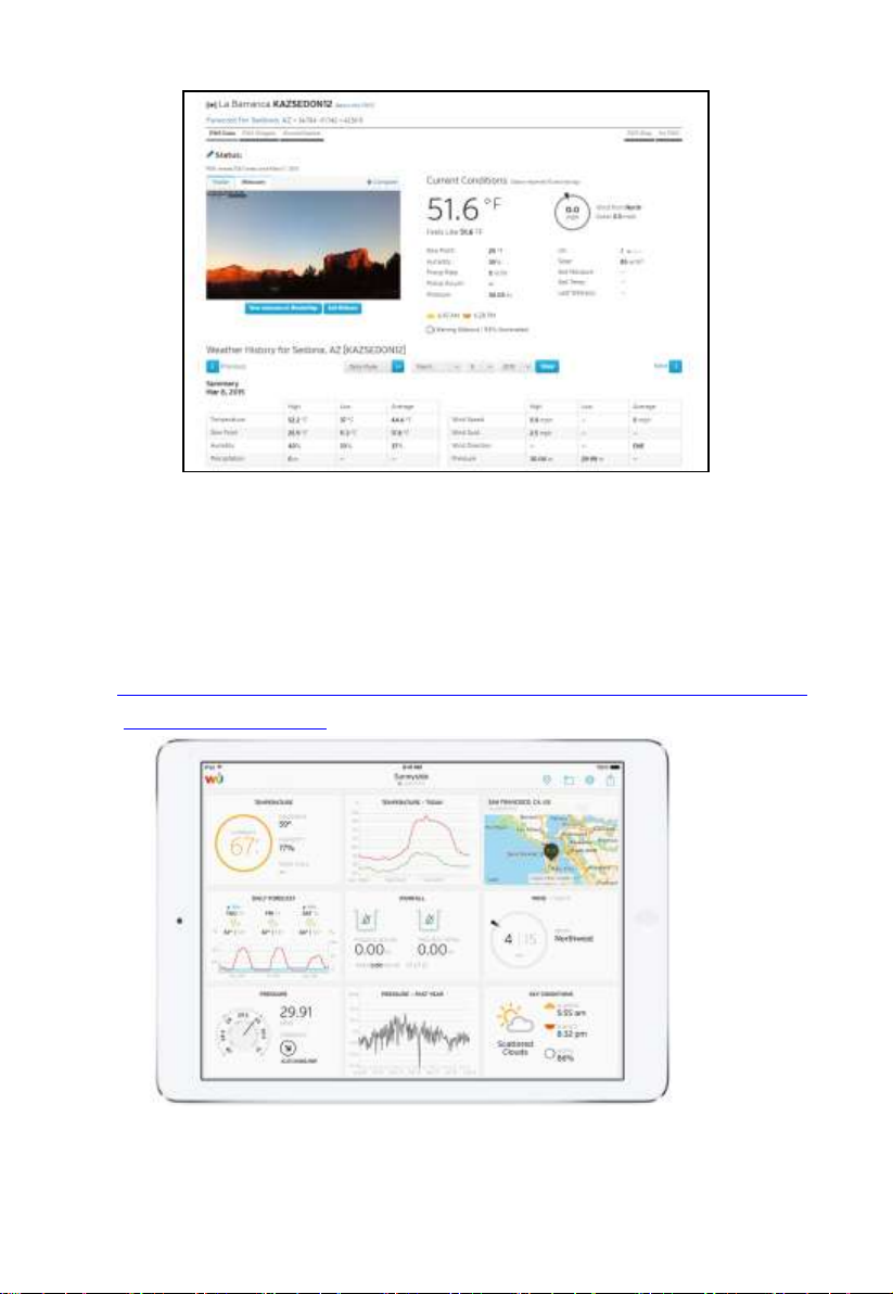
3)Viewing data on wunderground.com
The most basic way to observe your weather station’s data is by using the
wunderground.com web site. You will use a URL like this one, where your
station ID replaces the text “STATIONID”:
http://www.wunderground.com/personal-weather-station/dashboard?ID=ST
ATIONID
It will show a page such as this, where you can look at today’s data and
historical data as well:
Page 46
46
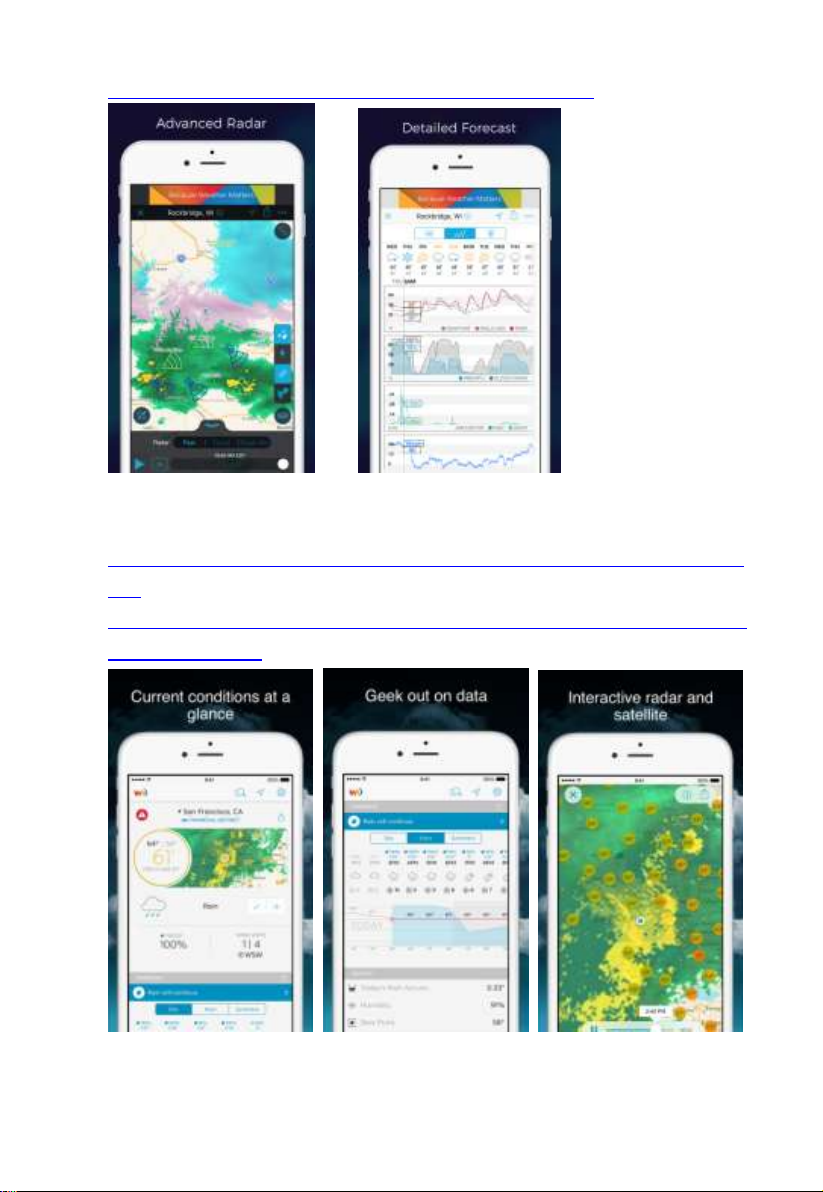
There are also some very useful mobile apps. The URLs provided here go to
the Web version of the application pages. You can also find them directly
from the iOS or Google Play stores:
WunderStation: iPad application for viewing your station’s data and
graphs
https://itunes.apple.com/us/app/wunderstation-weather-from-your-neigh
borhood/id906099986
WU Storm: iPad and iPhone application for viewing radar images,
animated wind, cloud coverage and detailed forecast, and PWS station
data
Page 47
47
https://itunes.apple.com/us/app/wu-storm/id955957721
Weather Underground: Forecast: iOS and Android application for
forecasts
https://itunes.apple.com/us/app/weather-underground-forecast/id486154
808
https://play.google.com/store/apps/details?id=com.wunderground.androi
d.weather&hl=en
Page 48
48
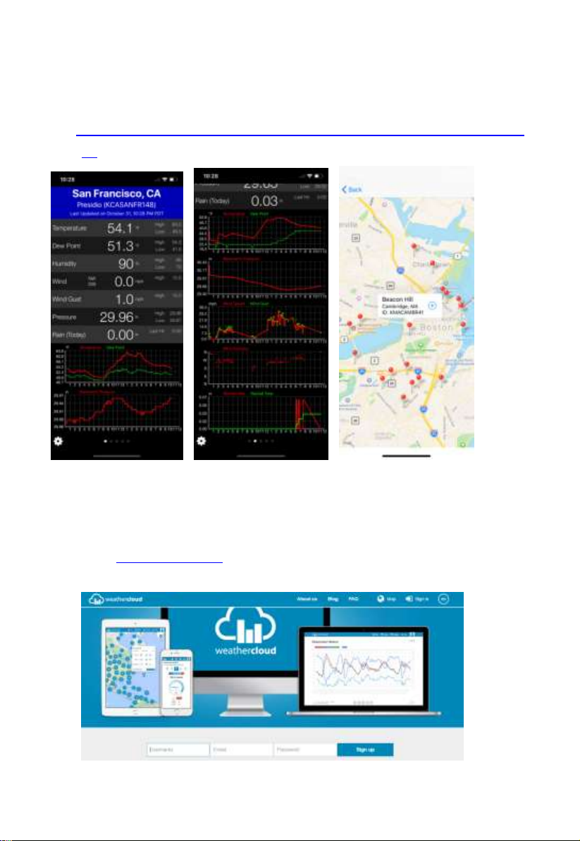
PWS Weather Station Monitor: View weather conditions in your
neighborhood, or even right in your own backyard. Connects to
wunderground.com
https://itunes.apple.com/us/app/pws-weather-station-monitor/id7137059
29
5.10.15.2 Weathercloud server setup
To register with Weathercloud follow these steps:
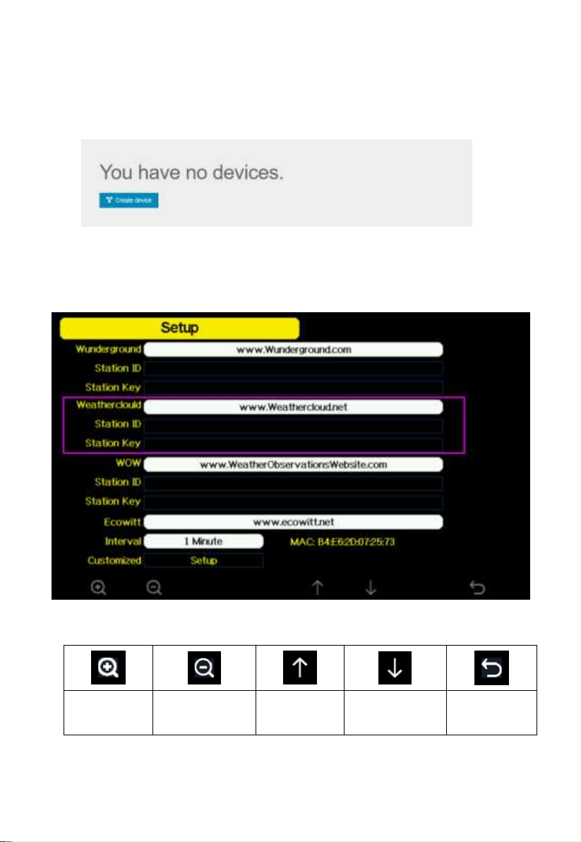
1) Visit weathercloud.net and enter a Username, Email and Password to
sign up.
Page 49
49
scroll value
up
scroll value
down
Scroll field
up
Scroll field
down
return to
Setup
2) Respond to the validation email from Weathercloud (it may take a few
minutes).
3) You will then be prompted to add a device/ Select “Create device” and
enter your station’s information:
4) After registering your station, take note of the “Weathercloud ID” and
“Key” presented to you.
5) Enter these values in the Weather Server:
Figure 31: Weathercloud Server setup screen
Page 50
50
5.10.15.3 Weather Observations Website (WOW) server setup
To have your weather station upload data to the Met Office’s WOW site you
will need to complete the following steps:
1) Sign Up with WOW
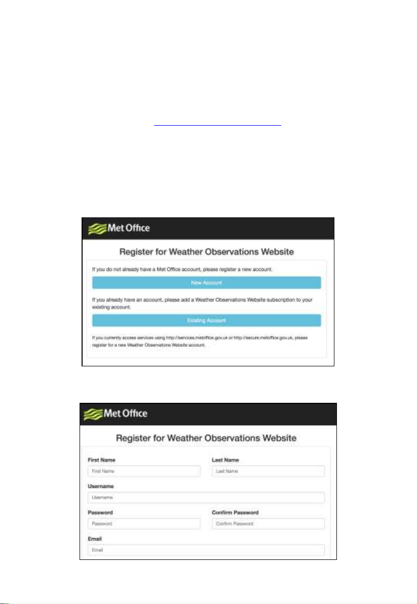
Navigate your browser to http://wow.metoffice.gov.uk. On the top-right side
of the resulting page you will see menu options. Click “Sign Up”
You will be presented with the screen below where you will choose to either
create a new account or use an already existing account. Click the desired
option.
If you chose “New Account” you will be presented with a form to fill out:
Page 51
51
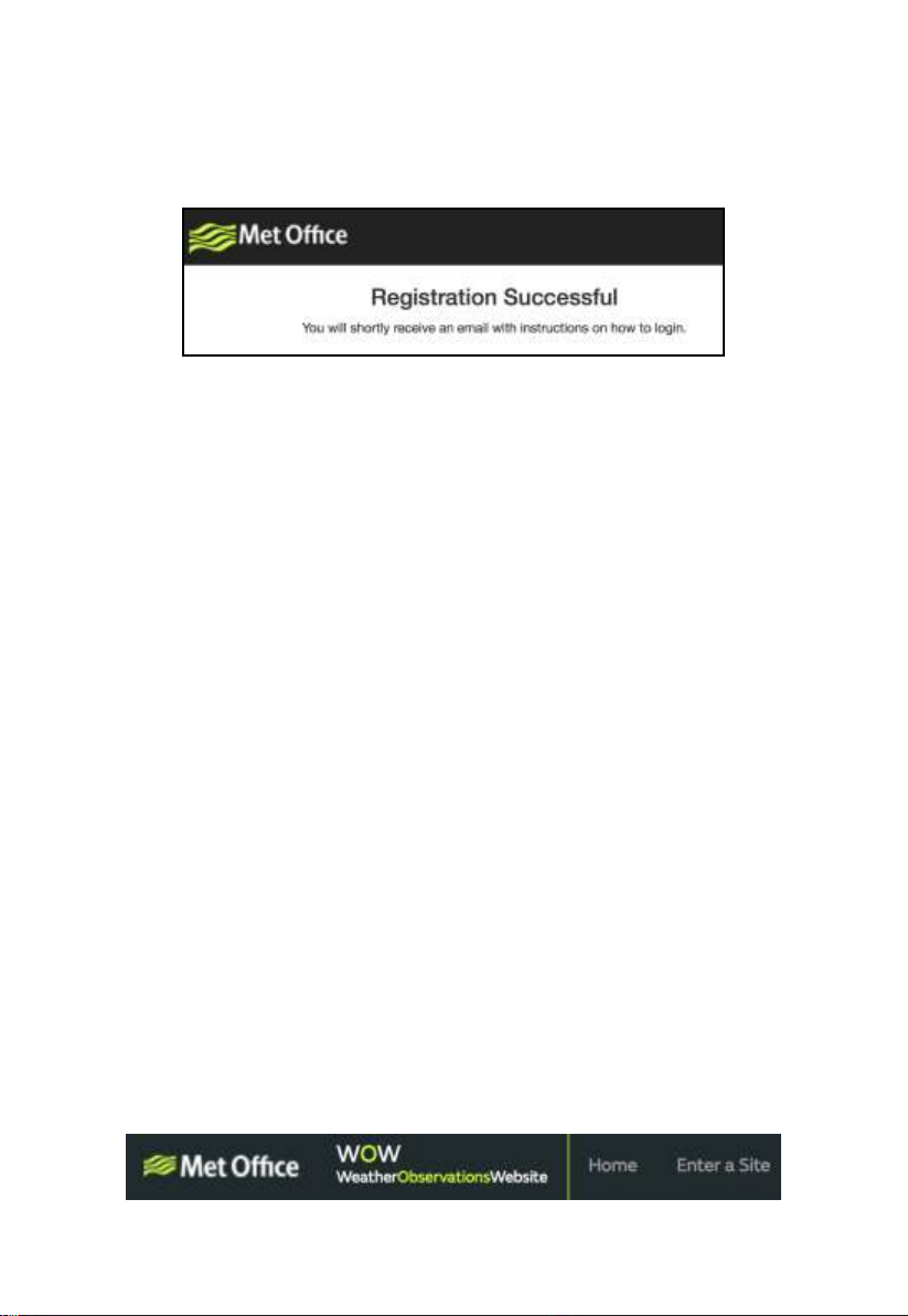
The actual form is longer, but all questions should be self-explanatory.
Complete and submit the form. You will receive the following notice on
completion:
2) Confirm your email with WOW
Respond to the validation email from WOW(it may take a few minutes).
3) Login to WOW
Follow instructions on the screen and login to the site.
4) Create/Set up a new WOW site
Once you are logged in you will need to create a new WOW site. “Sites” are
the means by which WOW organizes weather data the you contribute.
Basically, WOW builds a personal web site for your weather station.
Associated with the web site is two items you will need to allow uploading of
data:
Site ID: This is an arbitrary number that is used to distinguish your site from
another. This number appears (in brackets) next to or underneath the name of
your site on the site information page, for example:
6a571450-df53-e611-9401-0003ff5987fd
Authentication Key: This is a 6-digit number that is used to ensure data is
coming from you and not another user.
Begin setting up a new site by clicking “Enter a Site”:
Page 52
52
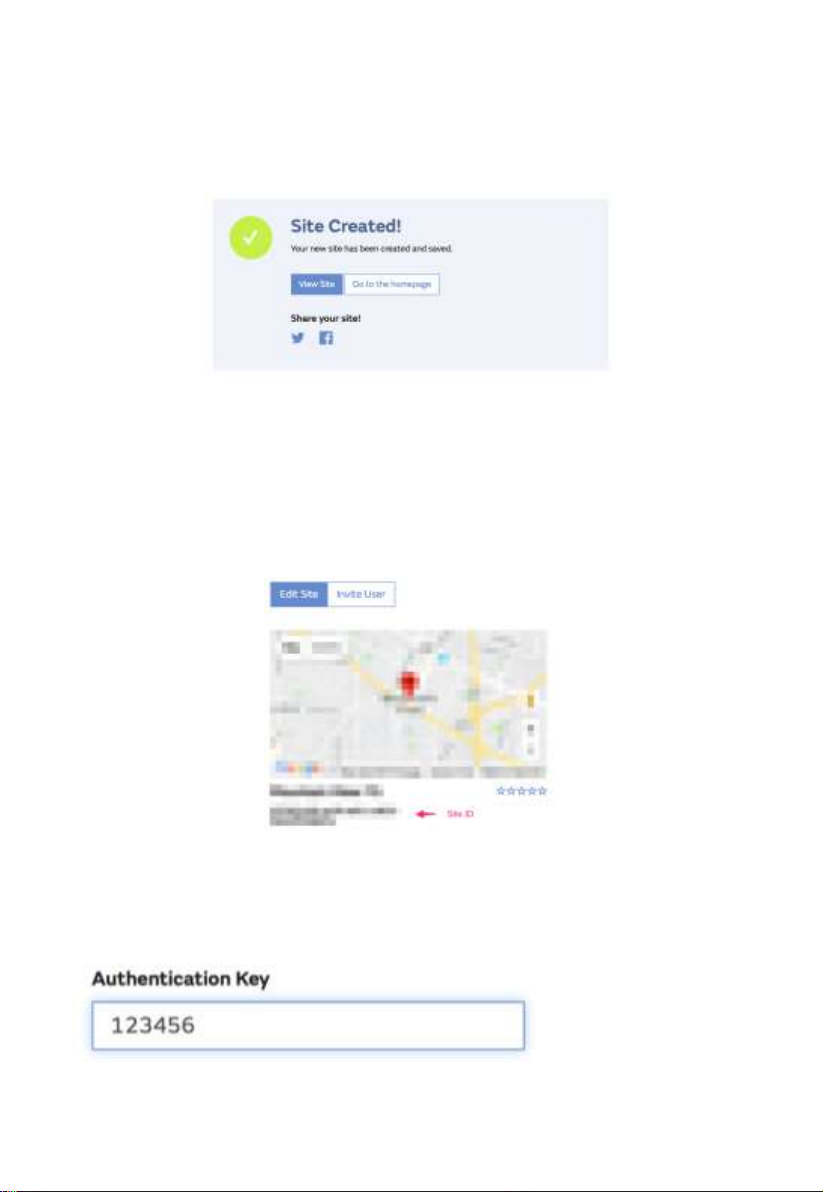
You will be presented with a form where you detail your station’s location
and a bunch of other settings related to how you wish the site to operate. After
you complete the setup, you should see:
Make sure you are (still) logged in to the WOW site. Login as necessary. Now
click on “My Sites” in the navigation bar at the top. If you have only 1 site,
you will now be shown its page. If you have multiple, you will have to choose
the correct one first. On this page, on the right side you will find the site id just
below the map:
You will also need to establish a unique 6 digits PIN code that you should
keep secret. It is the “Authentication Key.” Setup this number by clicking on
“Edit Site”) and filling out the with a 6-digit number of your choice:
Page 53
53
scroll value
up
scroll value
down
Scroll field
up
Scroll field
down
return to
Setup
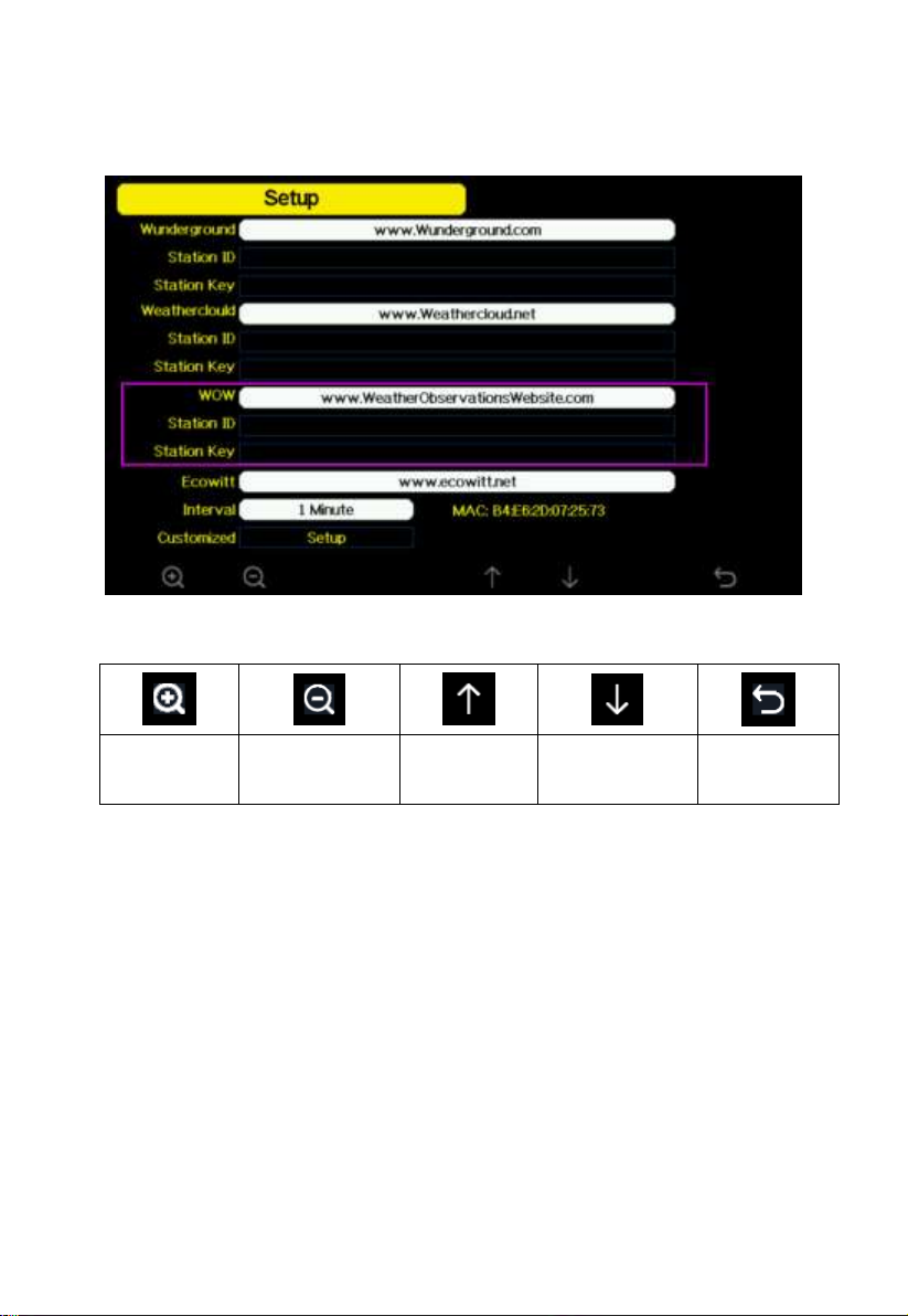
You will need both “Site ID” and “Authentication Key” to setup the upload
configuration for WOW in the Weather Server.
Figure 32: WOW Server setup screen
Page 54
54
5.10.15.4 Ecowitt.net server setup
scroll value
up
scroll value
down
Scroll field
up
Scroll field
down
return to
Setup
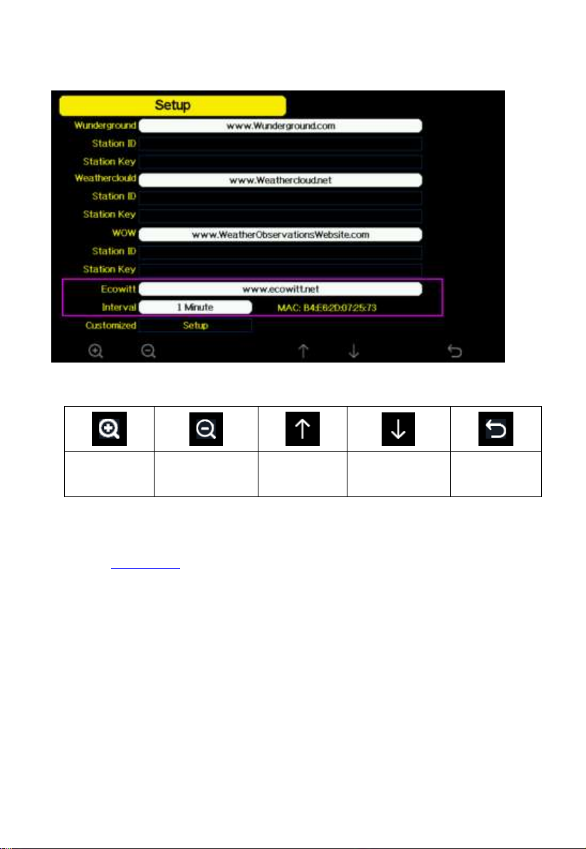
Figure 33: Ecowitt Server setup screen
To register with Ecowitt follow these steps:
1) Visit ecowitt.net and enter Email and Password to sign up.
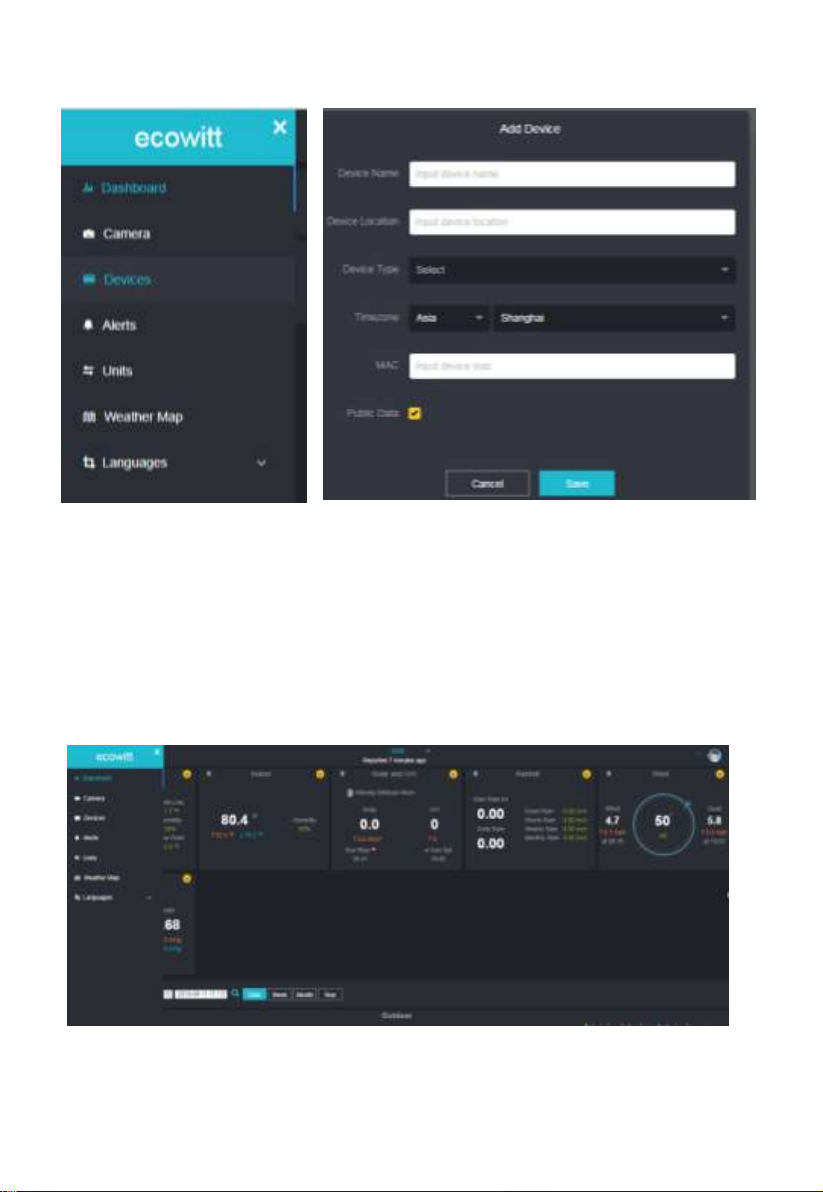
2) Press the upper left menu button and select Devices. Press Add Device
and input all the information needed, press save. MAC address found on
Ecowitt Server setup screen (错误!未找到引用源。), Note that this is
an example only and your MAC address will be different.
Page 55
55
Note: When select device address on map, please wait till the map display
before select your address.
Note: Please put in the correct time zone to get the correct time. Because the
time will be updated to internet time automatically while WIFI connection.
Once registered, select the dashboard to view your data, as shown below:
Page 56
56
Ecowitt.net is a responsive design and mobile friendly. Simply open your
mobile devices web browser, browse to ecowitt.net, and bookmark your
dashboard for quick access.
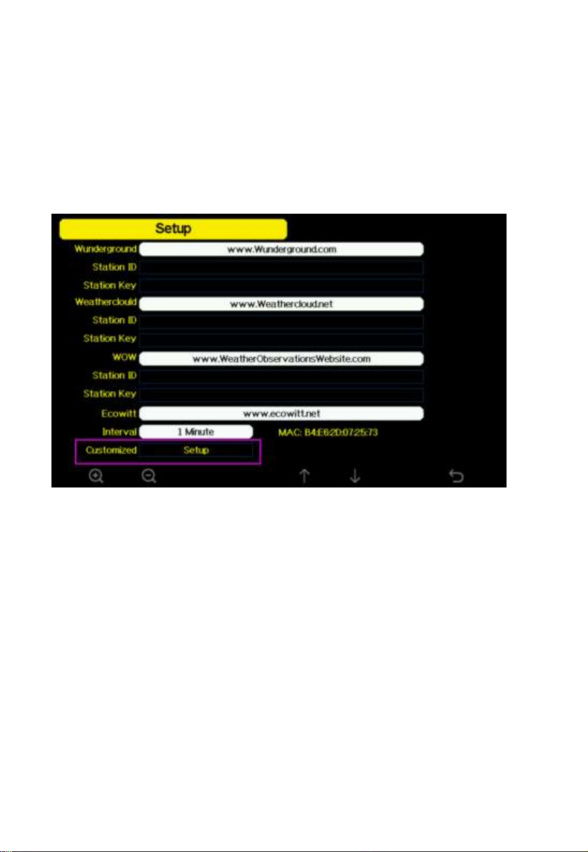
5.10.15.5 Customized server setup
For highly experienced users, it offers the option to send data to the user’s
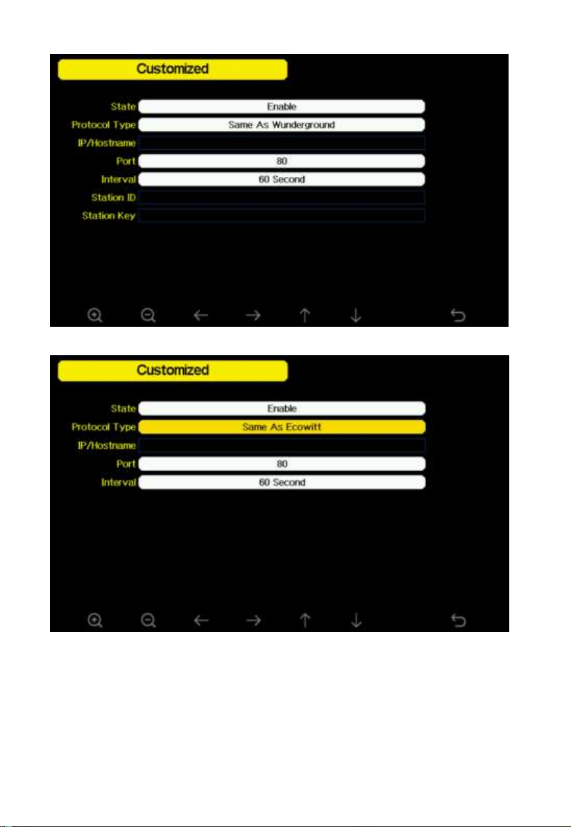
own server. Press the “setup” button to enter Customized setup screen,
Figure 34: Server setup screen
Select Enable button and select the protocol type. The website should has
the same protocol with Wunderground or Ecowitt. Input all the information
needed.
Page 57
57
Page 58
58
5.10.16 Wi-Fi scan
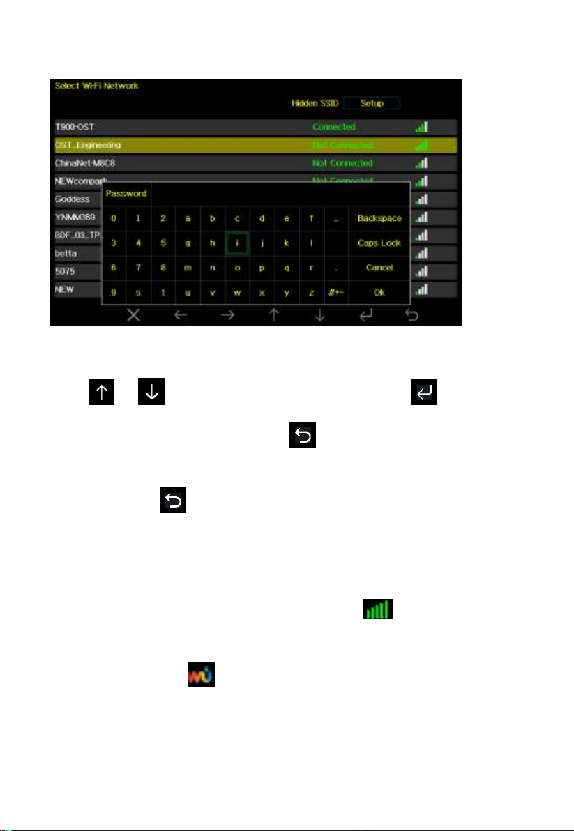
Figure 35: Select Wi-Fi Network Screen
Press or key to select the Wi-Fi network. Press key to
confirm and enter the password. Press key to return to normal display
mode. It is possible that your network is not listed when Wi-Fi Scan is
performed. Press button and restart Wi-Fi Scan, this will usually solve
the problem.
Only after connect to WLAN you can upload the data to weather website. If
the Wi-Fi network connects successfully, the icon will show on the left
top of the console display. If the data upload to Wunderground.com
successfully, the icon will show on the left top of the console display.
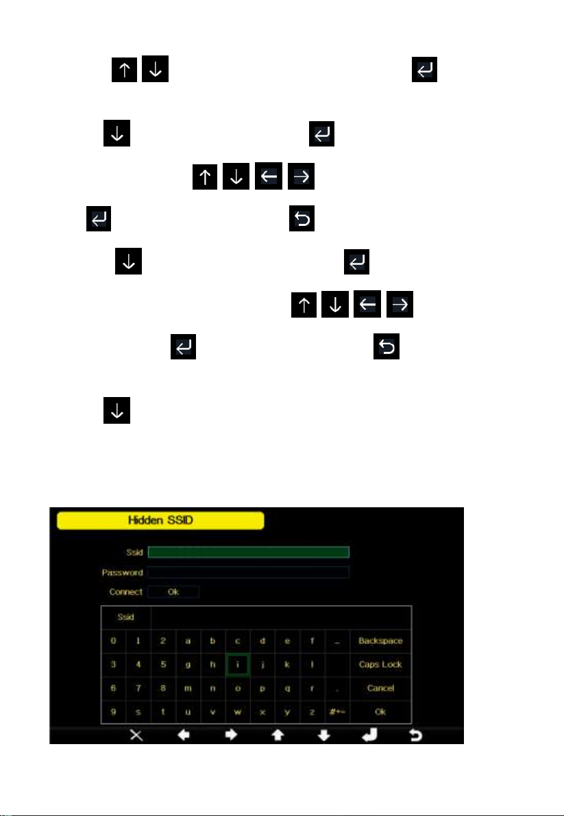
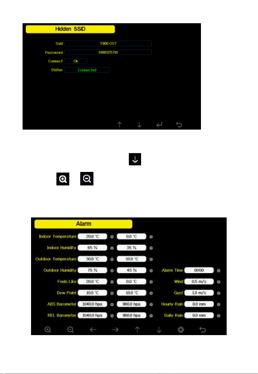
If the Wi-Fi network you would like to connect is with a hidden SSID, please
follow below steps to connect:
Page 59
59
1) Press to select Hidden SSID setup, and press key directly
to enter.
2).Press to highlight the SSID. Press to display the keyboard and
enter your SSID. Press to scroll to the character and
press to enter the character. Press to return to the setup page.
3). Press to highlight the Password. Press to display the keyboard
and start to enter your password.. Press to scroll to the
character and press to enter the character. Press to return to the
setup page.
4).Press to highlight the “OK” button beside “Connect ” to start
connecting.
After connected successfully, the status will display” Connected”.
Page 60
60
5.10.17 Background
While in Menu Setting Mode, press key to select Background Setup
field, press or key to choose between dark background display
and light background display
5.11 Alarm Setting Mode
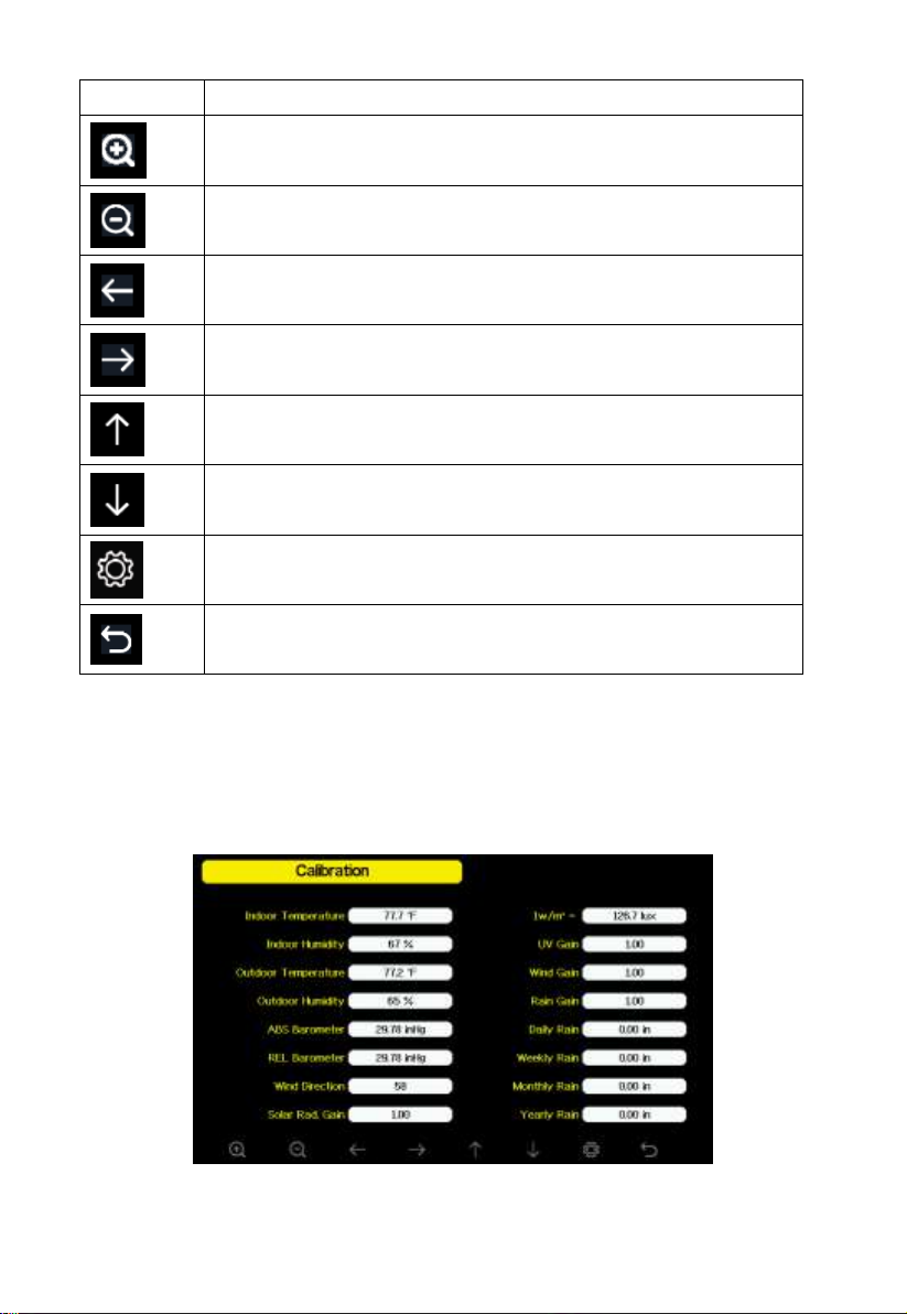
Figure 36: Alarm Setting Screen
Page 61
61
Icon
Description
Select key
Press this key to select the unit or scrolls the value
Select key
Press this key to select the unit or scrolls the value.
Left key
Press this key to select the set value.
Right key
Press this key to select the set value.
Up arrow key
Press this key to change the activated option field
Down arrow key
Press this key to change the activated option field
Set key
Press this key to select the Setting sub-Mode
Return key
Press this key to return to previous mode
The first row is high alarm value and the second row is low alarm value.
When weather alarm condition has been triggered, that particular alarm will
sound for 120 second and the corresponding icon will flash until the weather
condition doesn’t meet the user set level. Press any key to mute the alarm.
5.12 Calibration Mode
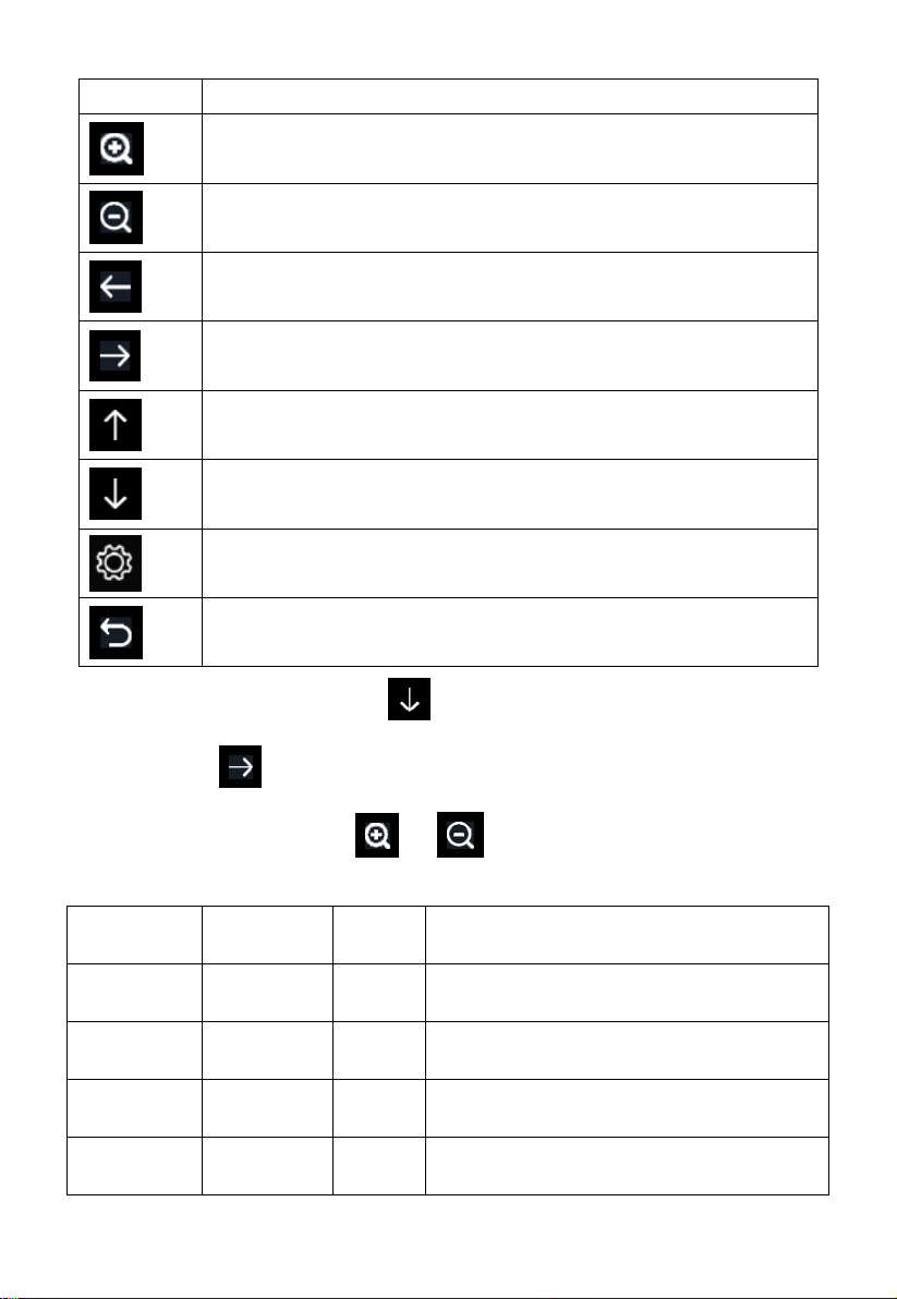
Figure 37: Calibraton Setting Screen
Page 62
62
Icon
Description
Select key
Press this key to select the unit or scrolls the value
Select key
Press this key to select the unit or scrolls the value.
Left key
Press this key to select the set value.
Right key
Press this key to select the set value.
Up arrow key
Press this key to change the activated option field
Down arrow key
Press this key to change the activated option field
Set key
Press this key to select the Setting sub-Mode
Return key
Press this key to return to previous mode
Parameter
Type of
Calibration
Default
Typical Calibration Source
Temperature
Offset
Current
Value
Red Spirit or Mercury Thermometer (1)
Humidity
Offset
Current
Value
Sling Psychrometer (2)
ABS
Barometer
Offset
Current
Value
Calibrated laboratory grade barometer
REL
Barometer
Offset
Current
Value
Local airport (3)
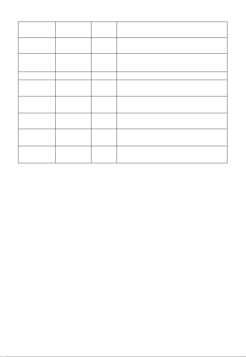
To adjust the parameter, press to scroll to the parameter you wish to
change. Press to highlight the sign (positive vs. negative, if applicable)
and significant digit. Press or to change the calibrated value.
Page 63
63
Wind
Direction
Offset
Current
Value
GPS, Compass (4)
Solar
Radiation
Gain
1.00
Calibrated laboratory grade solar radiation
sensor
1 w/m2
Gain
126.7
lux
Solar radiation conversion from lux to
w/m2 for wavelength correction (5)
Wind
Gain
1.00
Calibrated laboratory grade wind meter (6)
Rain
Gain
1.00
Sight glass rain gauge with an aperture of
at least 4” (7)
Daily Rain
Offset
Current
Value
Apply an offset if the weather station was
not operating for the entire day.
Weekly
Rain
Offset
Current
Value
Apply an offset if the weather station was
not operating for the entire week.
Monthly
Rain
Offset
Current
Value
Apply an offset if the weather station was
not operating for the entire month.
Yearly Rain
Offset
Current
Value
Apply an offset if the weather station was
not operating for the entire year.
(1) Temperature errors can occur when a sensor is placed too close to a
heat source (such as a building structure, the ground or trees).
To calibrate temperature, we recommend a mercury or red spirit
(fluid) thermometer. Bi-metal (dial) and digital thermometers (from
other weather stations) are not a good source and have their own
margin of error. Using a local weather station in your area is also a
poor source due to changes in location, timing (airport weather
stations are only updated once per hour) and possible calibration
errors (many official weather stations are not properly installed and
calibrated).
Place the sensor in a shaded, controlled environment next to the fluid
thermometer, and allow the sensor to stabilize for 3 hours. Compare
this temperature to the fluid thermometer and adjust the console to
match the fluid thermometer.
(2) Humidity is a difficult parameter to measure electronically and drifts
Page 64

64
over time due to contamination. In addition, location has an adverse
affect on humidity readings (installation over dirt vs. lawn for
example).
Official stations recalibrate or replace humidity sensors on a yearly
basis. Due to manufacturing tolerances, the humidity is accurate to
± 5%. To improve this accuracy, the indoor and outdoor humidity can
be calibrated using an accurate source, such as a sling psychrometer.
(3) The display console displays two different pressures: absolute
(measured) and relative (corrected to sea-level).
To compare pressure conditions from one location to another,
meteorologists correct pressure to sea-level conditions. Because the
air pressure decreases as you rise in altitude, the sea-level corrected
pressure (the pressure your location would be at if located at sea-level)
is generally higher than your measured pressure.
Thus, your absolute pressure may read 28.62 inHg (969 mb) at an
altitude of 1000 feet (305 m), but the relative pressure is 30.00 inHg
(1016 mb).
The standard sea-level pressure is 29.92 in Hg (1013 mb). This is the
average sea-level pressure around the world. Relative pressure
measurements greater than 29.92 inHg (1013 mb) are considered high
pressure and relative pressure measurements less than 29.92 inHg are
considered low pressure.
To determine the relative pressure for your location, locate an official
reporting station near you (the internet is the best source for real time
barometer conditions, such as Weather.com or Wunderground.com),
and set your weather station to match the official reporting station.
Page 65

65
(4) Only use this if you improperly installed the weather station sensor
array, and did not point the direction reference to true north.
(5) The default conversion factor based on the wavelength for bright
sunlight is 126.7 lux / w/m2 . This variable can be adjusted by
photovoltaic experts based on the light wavelength of interest, but for
most weather station owners, is accurate for typical applications, such
as calculating evapotransporation and solar panel efficiency.
(6) Wind speed is the most sensitive to installation constraints. The rule
of thumb for properly installing a wind speed sensor is 4 x the
distance of the tallest obstruction. For example, if your house is 20’
tall and you mount the sensor on a 5’ pole:
Distance = 4 x (20 – 5)’ = 60’ or =4 x (6.10-1.52)=18.32m.
Many installations are not perfect and installing the weather station
on a roof can be difficult. Thus, you can calibrate for this error with a
wind speed multiplier.
In addition to the installation challenges, wind cup bearings (moving
parts) wear over time.
Without a calibrated source, wind speed can be difficult to measure.
We recommend using a calibrated wind meter (not included) and a
constant speed, high speed fan.
(7) The rain collector is calibrated at the factory based on the funnel
diameter. The bucket tips every 0.01” or 0.1m of rain (referred to as
resolution). The accumulated rainfall can be compared to a sight glass
rain gauge with an aperture of at least 4” or 0.1m.
Make sure you periodically clean the rain gauge funnel.
Page 66
66
Note: The purpose of calibration is to fine tune or correct for any sensor error
associated with the devices margin of error. Errors can occur due to electronic
variation (example, the temperature sensor is a resistive thermal device or
RTD, the humidity sensor is a capacitance device), mechanical variation, or
degradation (wearing of moving parts, contamination of sensors).
Calibration is only useful if you have a known calibrated source you can
compare it against, and is optional. This section discusses practices,
procedures and sources for sensor calibration to reduce manufacturing and
degradation errors. Do not compare your readings obtained from sources such
as the internet, radio, television or newspapers. The purpose of your weather
station is to measure conditions of your surroundings, which vary
significantly from location to location.
NOTE: UV Calibration MUST be performed every 2 to 3 months to
improve results. Over time, UV Index may alter results based on bright and
strong sunlight conditions. This is why diligent UV Calibration is
recommended.
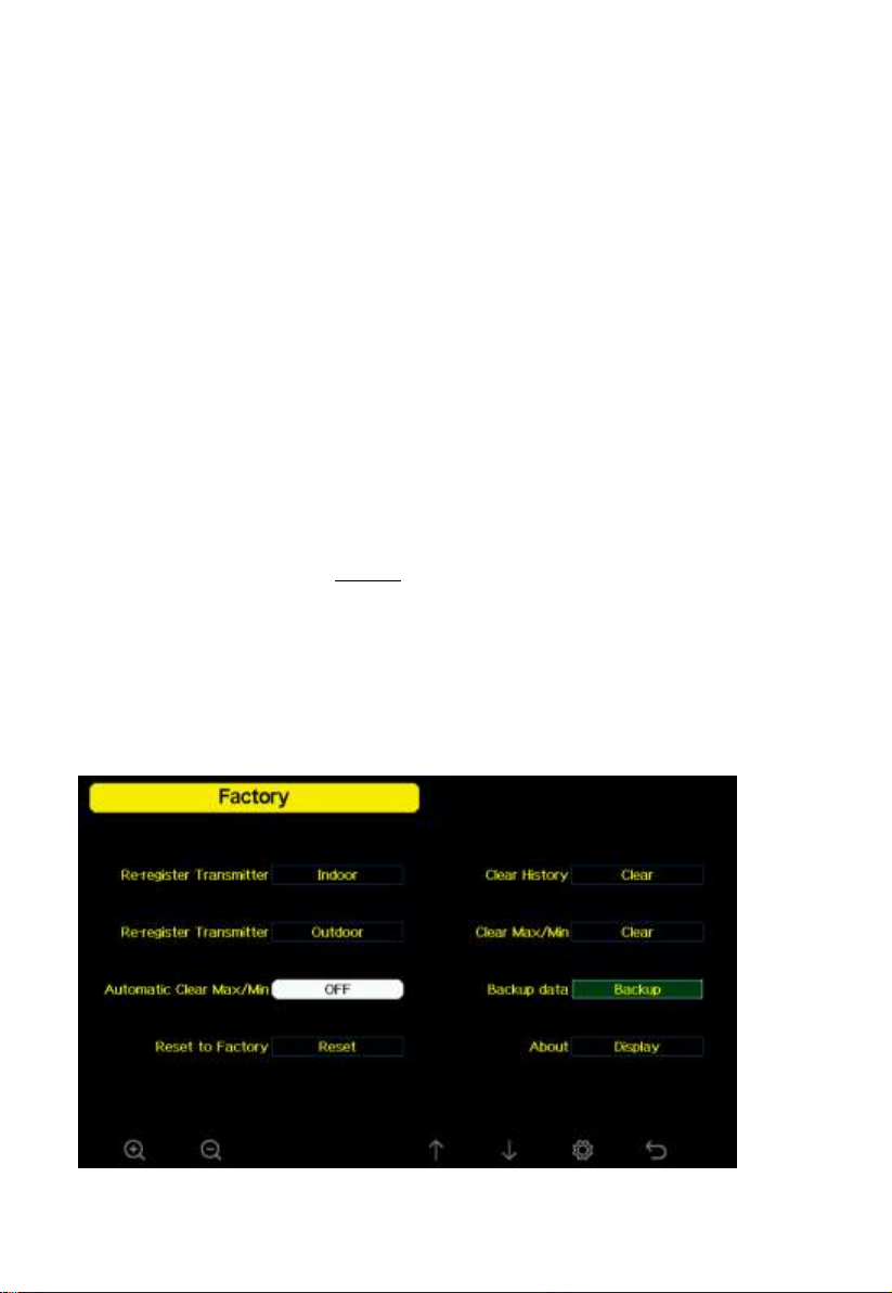
5.13 Factory reset
Figure 38: Factory Reset Screen
Page 67
67
5.13.1 Re-register indoor transmitter
Press or key to select re-register indoor transmitter. Press
or key to popup the Message Box ”Register a new indoor
transmitter?” Press or to select Yes or No. Press the or
key to confirm the selection.
5.13.2 Re-register outdoor transmitter
Please reference section 6.7.1. Procedures and settings are similar to
re-register indoor transmitter
5.13.3 Automatic Clear Max/Min
To turn on/off automatically clear Max/Min record at 0:00hr every day.
Press or key to select Automatic clear Max/Min. Press or
key to switch on/off.
When it is selected with ON option, min/max will be presented as daily
min/max, and with OFF option selected, it is for history min/max record.
5.13.4 Reset to Factory
Press or key to select Reset to Factory. Press or key
to popup the Message Box ”Reset to factory default?” Press or
to select Yes or No. Press the or key to confirm the selection.
Page 68
68
5.13.5 Clear History
Press or key to select Clear History. Press or key to
popup the Message Box ”Clear the history record?” Press or to
select Yes or No. Press the or key to confirm the selection.
5.13.6 Clear Max/Min
Press or key to select Clear Max/Min. Press or key
to popup the Message Box ”Clear the max/min record?” Press or
to select Yes or No. Press the or key to confirm the selection.
5.13.7 Backup data
Press or key to select Backup data. Press or key to
popup the Message Box ”Copy history data to SD card?” Press or
to select OK or Cancel. Press the or key to confirm the
selection.
Note: You need to insert a SD card(not included) into the console before
using this function.
Page 69
69
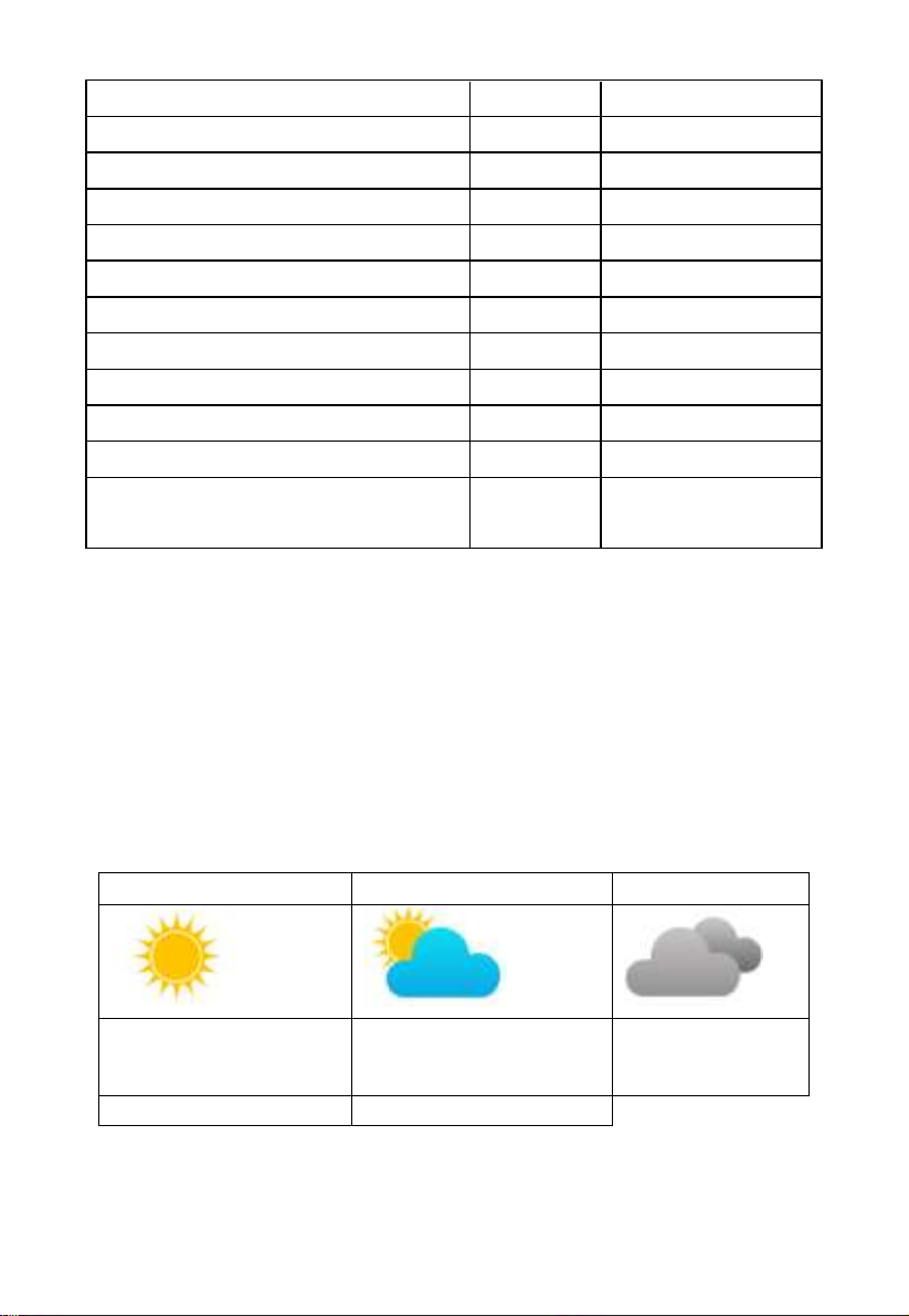
Wind speed
Beaufort
number
Description
0 - 1 mph, or 0 - 1.6 km/h
0
Calm
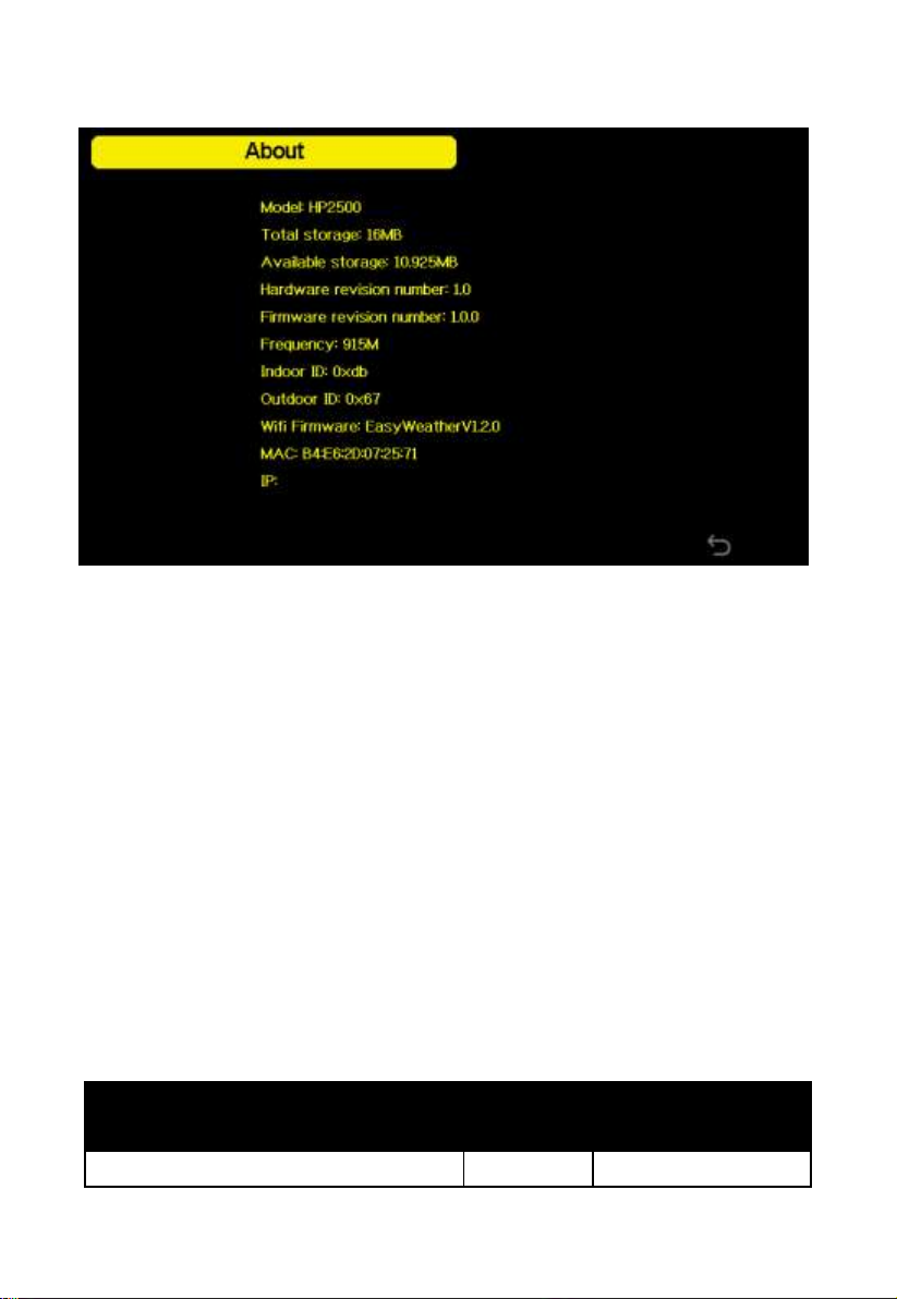
5.13.8 About information
Figure 39: About information Screen
Note: This figure is just for reference(model and frequency will change
according to different market). The actual display console may be with higher
firmware version than this manual described because we will update the
firmware occasionally.
6. Other Console Functions
6.1Beaufort Wind Force Scale
If you have selected the use of Beaufort wind speed units, you can use the
table below for reference. The Beaufort scale is based on qualitative wind
conditions and how they would affect a ship’s (frigate) sails (so yes, it is an
“old” standard). It is therefore less precise than the other scales but is still in
use in various locales.
Page 70
70
1 - 3 mph, or 1.6 - 4.8 km/h
1
Light air
3 - 7 mph, or 4.8 - 11.3 km/h
2
Light breeze
7 - 12 mph, or 11.3 -1 9.3 km/h
3
Gentile breeze
12 - 18 mph, or 19.3 - 29.0 km/h
4
Moderate breeze
18 - 24 mph, or 29.0 - 38.6 km/h
5
Fresh breeze
24 - 31 mph, or 38.6 - 49.9 km/h
6
String breeze
31 - 38 mph, or 49.9 - 61.2 km/h
7
Near gale
38 - 46 mph, or 61.2 - 74.1 km/h
8
Gale
46 - 54 mph, or 74.1 - 86.9 km/h
9
Strong gale
55 - 63 mph, or 88.5 - 101.4 km/h
10
Storm
64 - 73 mph, or 103 - 117.5 km/h
11
Violent storm
74 mph and above, or 119.1 km/h
and above
12
Hurricane
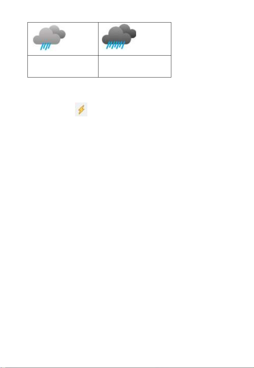
Sunny
Partly Cloudy
Cloudy
Pressure increases for a
sustained period of time
Pressure increases slightly
or initial power up
Pressure decreases
slightly
Rainy
Stormy
Table 1: Beaufort wind force scale
6.2Weather Forecasting
The five weather icons are Sunny, Partly Cloudy, Cloudy, Rainy and
Stormy.
The forecast icon is based on the rate of change of barometric pressure.
Please allow at least one month for the weather station to learn the
barometric pressure over time.
Page 71
71
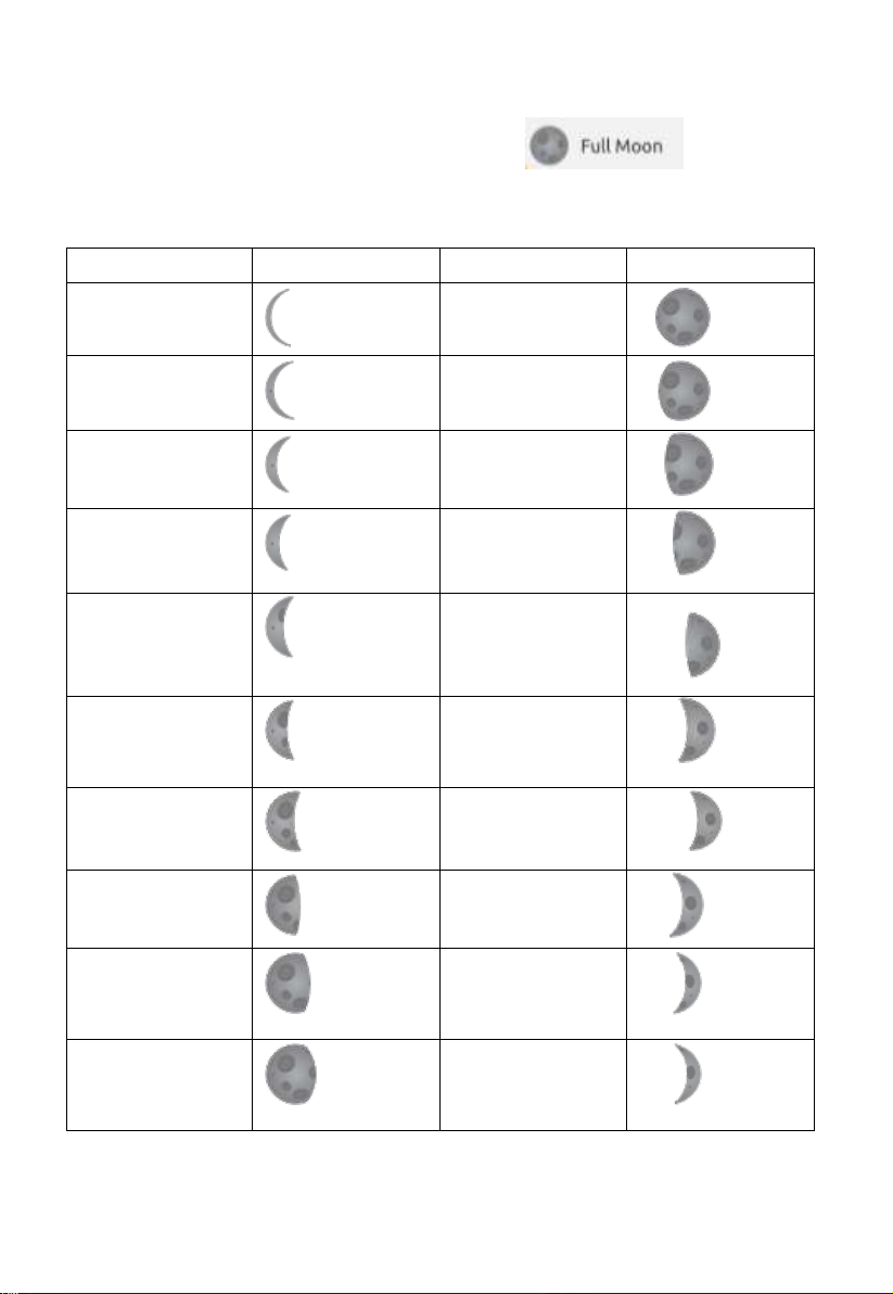
Pressure decreases for a
sustained period of time
Pressure rapidly
decreases
6.3 Lightning Alert
The lightning icon will appear if the Dew Point exceeds 70 F. This
means there is a chance of lightning storms forming.
6.4 Weather Forecasting Description and Limitations
In general, if the rate of change of pressure increases, the weather is generally
improving (sunny to partly cloudy). If the rate of change of pressure decreases,
the weather is generally degrading (cloudy, rainy or stormy). If the rate of
change is relatively steady, it will read partly cloudy.
The reason the current conditions do not match the forecast icon is because
the forecast is a prediction 24-48 hours in advance. In most locations, this
prediction is only 70% accurate and it is a good idea to consult the National
Weather Service for more accurate weather forecasts. In some locations, this
prediction may be less or more accurate. However, it is still an interesting
educational tool for learning why the weather changes.
The National Weather Service (and other weather services such as
Accuweather and The Weather Channel) have many tools at their disposal to
predict weather conditions, including weather radar, weather models, and
detailed mapping of ground conditions.
Page 72
72
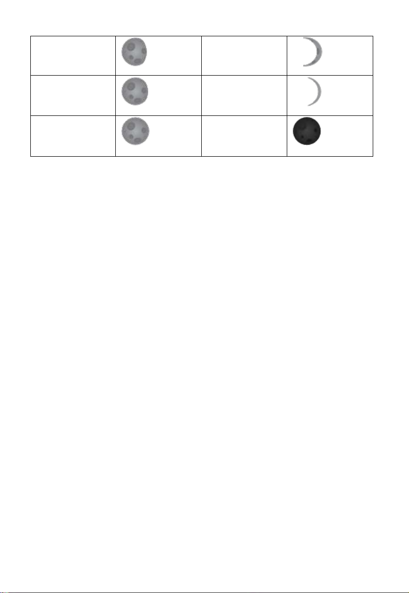
Moon Phase
Image
Moon Phase
Image
Day 1
Day 14
Day 2
Day 15
Day 3
Day 16
Day 4
Day 17
Day 5
Day 18
Day 6
Day 19
Day 7
Day 20
Day 8
Day 21
Day 9
Day 22
Day 10
Day 23
6.5Moon Phase
In the event the moon phase is 100%, the icon will appear in
its place. In the event of 0%, the word “New Moon” will appear in its place.
Page 73
73
Day 11
Day 24
Day 12
Day 25
Day 13
Full Moon
Day 26
New Moon
Page 74
74
7. Maintenance
The following steps should be taken for proper maintenance of your station
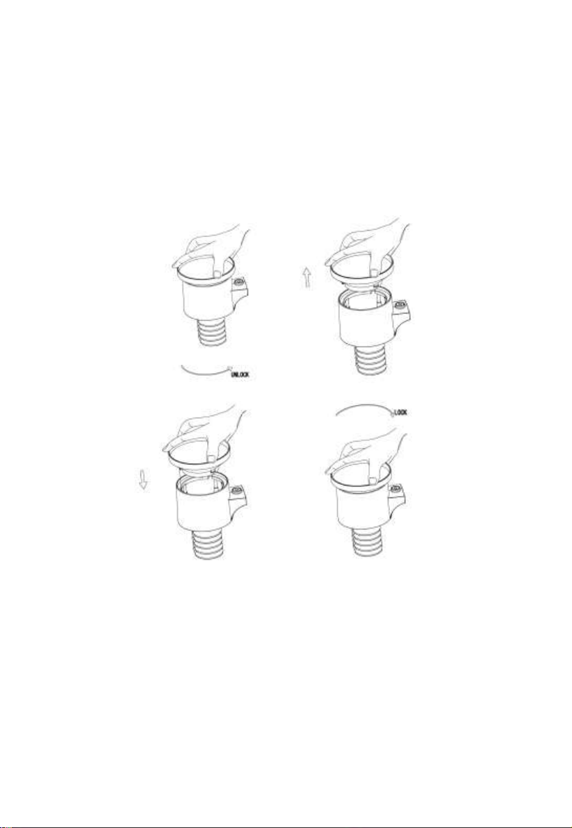
1.Clean the rain gauge once every 3 months. Rotate the funnel
counter-clockwise and lift to expose the rain gauge mechanism, and clean
with a damp cloth. Remove any dirt, debris and insects. If bug infestation is an
issue, spray the array lightly with insecticide.
Figure 40: Rain gauge maintenance
2.Clean the solar radiation sensor and solar panel every 3 months with a
non-abrasive slightly damp cloth.
3.Replace batteries every 1-2 years. If left in too long, the batteries may
leak due to environmental challenges. In harsh environments, inspect the
batteries every 3 months (while cleaning the solar panel).
4.When replacing the batteries, apply a corrosion preventing compound
on the battery terminals, available at Amazon and most hardware stores.
5. In snowy environments, spray the top of the weather station with
anti-icing silicon spray to prevent snow build up.
Page 75
75
Problem
Solution
Wireless remote
(thermo-hygrometer) not
reporting in to console.
There are dashes on the
display console.
The maximum line of sight communication range
is about 150m. Move the sensor assembly closer
to the display console.
Resynchronize the remote sensor(s). Reference
Section 5.13.1&5.13.2.
Install a fresh set of batteries in the remote
sensor(s).
Make sure the remote sensors are not transmitting
through solid metal (acts as an RF shield), or earth
barrier (down a hill).
Radio Frequency (RF) Sensors cannot transmit
through metal barriers (example, aluminum
siding) or multiple, thick walls.
Move the display console around electrical noise
generating devices, such as computers, TVs and
other wireless transmitters or receivers.
Outdoor sensor array
does not communicate to
the display console.
The sensor array may have initiated properly and
the data is registered by the console as invalid,
and the console must be reset. Press the reset
button as described in Section Installation.
With an open ended paperclip, press the reset
button for 3 seconds to completely discharge the
voltage.
Take out the batteries and wait one minute, while
covering the solar panel to drain the voltage.
10. Troubleshooting Guide
Look through the following table and locate an issue or problem you are
experiencing in the left column and read possible solutions in the right
column.
Page 76
76
Problem
Solution
Put batteries back in and resync with console by
powering down and up the console with the
sensor array about 10 feet away.
Bring the sensor array inside the house (you can
disconnect it from the rest of the sensors). The
LED next to the battery compartment will flash
every 16 seconds. If the LED is not flashing
every 16 seconds…
Replace the batteries in the outside sensor array.
If the batteries were recently replaced, check the
polarity. If the sensor is flashing every 48
seconds, proceed to the next step.
There may be a temporary loss of communication
due to reception loss related to interference or
other location factors,
or the batteries may have been changed in the
sensor array and the console has not been reset.
The solution may be as simple as powering down
and up the console.
Replace the batteries in the outside sensor array.
With the sensor array and console 10 feet away
from each other, remove AC power from the
display console and wait 10 seconds. Re-connect
power.
Temperature sensor
reads too high in the day
time.
Make certain that the sensor array is not too close
to heat generating sources or strictures, such as
buildings, pavement, walls or air conditioning
units.
Use the calibration feature to offset installation
issues related to radiant heat sources. Reference
6.6.
Page 77
77
Problem
Solution
Absolute pressure does
not agree with official
reporting station
You may be viewing the relative pressure, not the
absolute pressure.
Select the absolute pressure. Make sure you
properly calibrate the sensor to an official local
weather station. Reference Section 6.6 for details.
Rain gauge reports rain
when it is not raining
An unstable mounting solution (sway in the
mounting pole) may result in the tipping bucket
incorrectly incrementing rainfall. Make sure you
have a stable, level mounting solution.
Data not reporting to
Wunderground.com
1. Confirm your password is correct. It is
the password you registered on
Wunderground.com. Your
Wunderground.com password cannot
begin with a non-alphanumeric character
(a limitation of Wundeground.com, not
the station). Example, $oewkrf is not a
valid password, but oewkrf$ is valid.
2. Confirm your station ID is correct. The
station ID is all caps, and the most
common issue is substituting an O for a 0
(or visa versa). Example,
KAZPHOEN11, not KAZPH0EN11
3. Make sure the date and time is correct on
the console. If incorrect, you may be
reporting old data, not real time data.
4. Make sure your time zone is set properly.
If incorrect, you may be reporting old
data, not real time data.
5. Check your router firewall settings. The
console sends data via Port 80.
Page 78
78
Problem
Solution
No WiFi connection
1. Check for WiFi signal strength symbol on the
display . If wireless connectivity is
successful and reporting to
Wunderground.com, the WiFi icon
will be displayed the home page.
2. Make sure your modem WiFi settings are
correct (network name, password and
security settings).
Page 79
79
TERM
DESCRIPTION
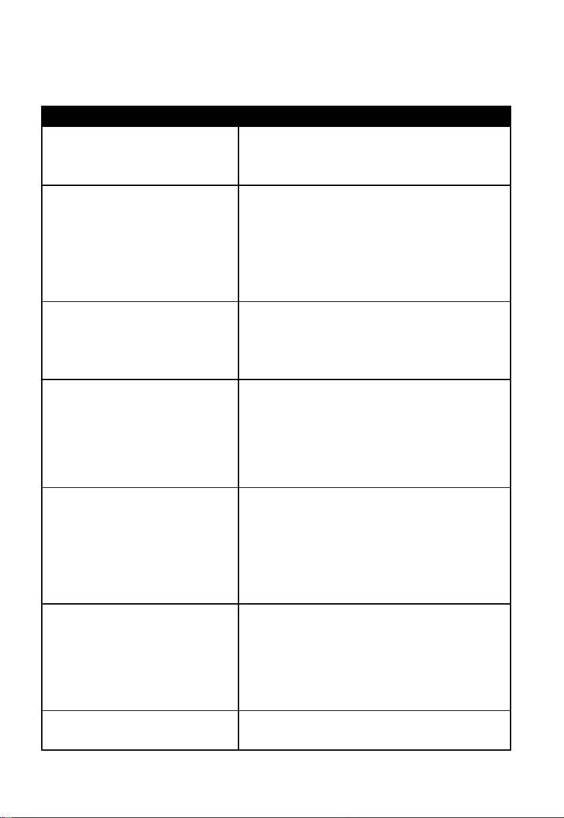
ABSOLUTE AIR PRESSURE
ABSOLUTE BAROMETRIC
PRESSURE
Absolute air pressure is the air pressure
registered on a barometer without regard to
altitude.
BAROMETER
A barometer is a device that measures the
pressure of the air pushing on it—this
measurement is called the barometric
pressure. We don’t actually feel the
barometric pressure because the air pressure
is pushing equally in every direction.
BEAUFORT (Bft)
An indicator of wind force strength (not
speed) as it would act on a ship’s sails. Still
commonly in used in some locales to
indicate wind force.
DEW POINT
The temperature to which air must be cooled
to become saturated with water vapor. When
further cooled, the airborne water vapor will
condense to form liquid water (dew), or frost
if below freezing.
HEAT INDEX
The heat index (HI) or humiture is an index
that combines air temperature and relative
humidity, in shaded areas, as an attempt to
determine the human-perceived equivalent
temperature, as how hot it would feel if the
humidity were some other value in the shade.
HECTOPASCALS (hPa)
This is an international standard (SI system)
for measuring air pressure. It used to be
referred to as milli-bar (mb) and sometimes
still is. They are equivalent.
HYGROMETER
An instrument that measure relative
humidity of the air. This is expressed as a
11. Glossary of Common Terms
Page 80
80
TERM
DESCRIPTION
percentage between 0% and 100%.
INCHES OF MERCURY
(inHg)
This is the common unit of measurement for
air pressure in the United States. It refers to
the length of a standard column of mercury
(a liquid metal) that can be pushed up by the
ambient air pressure. Standard pressure is
approximately 29.92 inHg
KNOTS (kn)
One knot is equivalent to one nautical mile
and is sometimes used to indicate wind
speed.
LCD
An acronym for “Liquid Crystal Display.”
This is a common type of display screen used
in televisions, computers, watches, and digital
clocks.
LUX (lx)
The unit of illuminance (a measure of the
intensity of illumination on a surface) as used
in the SI system.
MILLIBAR (mb)
See HECTOPASCALS.
MM OF MERCURY (mmHg)
This is similar to inches of mercury, except
expressed in millimeters. Standard pressure is
approximately 760 mmHg.
NIST
National Institute of Standards and
Technology. A United States institute that
keeps very accurate time using atomic
clocks and provides and internet-based
service to accurately set device clocks.
RELATIVE AIR PRESSURE
RELATIVE BAROMETRIC
PRESSURE
Relative air pressure is the absolute air
pressure compensated for the altitude of the
barometer. The result is what the air pressure
would be at sea level.
TFT
Thin-Film-Transistor, a type of LCD screen.
ULTRA VIOLET INDEX
The ultraviolet index or UV-Index (UVI) is an
international standard measurement of the
strength of sunburn-producing ultraviolet
Page 81
81
TERM
DESCRIPTION
(UV) radiation at a particular place and time.
The purpose of the UV Index is to help people
effectively protect themselves from UV
radiation. The UV Index is a linear scale, with
higher values representing a greater risk of
sunburn (which is correlated with other health
risks) due to UV exposure. An index of 0
corresponds to zero UV radiation, as is
essentially the case at night. An index of 10
corresponds roughly to midday summer
sunlight with a clear sky when the UV Index
was originally designed, but values above 10
are sometimes possible. Levels above 8 are
considered “very high” and above 11 are
considered “extreme.”
WIND CHILL
Wind chill (popularly wind chill factor) is the
lowering of body temperature due to the
passing-flow of lower-temperature air. In
other words, the air “feels” colder than it is
because of the chilling effect of the wind on
the skin.
Table: Glossary of terms
Page 82
82
Outdoor sensor
Specification
Transmission distance in open
field
100 m (330 ft.)
RF Frequency
433 / 868 MHz depending on location
Temperature range
-40°C – 60°C (-40°F - 140°F)
Temperature accuracy
± 1°C, or ± 2°F
Temperature resolution
0.1°C, or 0.1°F
Humidity range
10% ~ 99%
Humidity accuracy
± 5%
Humidity resolution
1%
Rain volume display range
0 – 9999 mm, or 0 – 199.99 in
Rain volume accuracy
± 10%
Rain volume resolution
0.3 mm (for volume < 1,000 mm)
1 mm (for volume ≥ 1,000 mm), or
0.01 in (for volume < 100 in)
1 mm (for volume ≥ 100 in)
Wind speed range
0 – 50 m/s (0 ~ 100 mph)
Wind speed accuracy
± 1 m/s (speed < 5 m/s)
± 10% (speed ≥ 5 m/s), or
± 0.1 mph (speed < 11 mph)
± 10% (speed ≥ 11 mph)
UV-Index range
0 - 15
Light range
0 – 120 kLux
Light accuracy
± 15%
Sensor reporting interval
16 seconds
12. Specifications
Note: Out of range values will be displayed using “---”:
Table: Outdoor sensor specification
Page 83
83
Indoor sensor
Specification
Temperature range
-10°C – 60°C (14°F - 140°F)
Temperature resolution
0.1°C, or 0.1°F
Humidity range
10% ~ 99%
Humidity resolution
1%
Barometric pressure range
300 – 1,100 hPa (8.85 – 32.5 inHg)
Barometric pressure accuracy
± 3 hPa in 700 – 1,100 hPa range
Barometric pressure resolution
0.1 hPa (0.01 inHg)
Sensor reporting interval
60 seconds
Alarm Duration
120 seconds
Power
Specification
Base station/console
5V DC Adapter (included)
Indoor sensor
2 x AA 1.5 Alkaline batteries (not included)
Outdoor sensor
Solar panel (built-in)
Outdoor sensor (backup)
2 x AA 1.5V LR6 Alkaline (not included), or
2 x AA 1.5V Lithium battery (not included)
Table: Indoor sensor specification
Table: Power specification
The primary power source for the outdoor sensor is the solar panel. When
available solar power (light over recent period) is insufficient, the batteries
will be used. In outdoor climates that frequently have sustained temperatures
below 0°C (or 32°F) the use of Lithium batteries is strongly suggested as
these are performing better than Alkaline batteries under such circumstances.
 Loading...