

Page 1
finecom
FLM-520 User’s Guide
- -
1
TFT LCD monitor TFT LCD monitor TFT LCD monitor TFT LCD monitor TFT LCD monitorTFT LCD monitor TFT
FLM-520
User’s Guide
FLM-520 LCD Monitor
Finecom Co., Ltd.
Fine B/D. 673-5 Dungchon-dong,
Kangseo-ku, Seoul 157-030, Korea.
Tel : 82-2-3662-5811
Fax : 82- 2-3663-0987
Web site : http://www.finecom.co.kr
fine&good fine&good fine&good fine&good fine&good fine&good fine&good fine&good fine&good fine&good fine&good
Page 2
finecom
FLM-520 User’s Guide
- -
2
Index
FCC Notice 4
1. Outline 5
1-1) Introduction to FLM-520 5
1-2) Features 5
2. Components & parts name 6
2-1) Components 6
2-2) Front & Rear View 6
3. Installation 7
4. Speaker 8
5. External Keypad 9
5-1) External Keypad 9
5-2) Function of Push-button 9
6. OSD Overview 10
6-1) Power On Default Settings 10
6-2) Value Controls 10
6-3) LED Active Source Indicator 10
6-4) Warning Message 10
7. OSD Menu Items 11
7-1) RGB Menu 12
7-1-1) Brightness 12
7-1-2) Red and Blue Controls 12
7-1-3) Green... 12
7-1-4) Blue ... 12
7-1-5) Color Temp 12
7-1-6) Sharpness 12
Page 3
finecom
FLM-520 User’s Guide
- -
3
7-2) Geometry Menu 13
7-2-1) Auto-Adjustment 13
7-2-2) H. Position 13
7-2-3) V. Position 13
7-2-4) H. Total 13
7-2-5) Auto Phase 13
7-2-6) Delay 13
7-3) Contrast Menu 14
7-3-1) Auto-Balance 14
7-3-2) Contrast 14
7-3-3) Red 14
7-3-4) Green 14
7-3-5) Blue 14
7-4) Info 15
7-5) Input Type 15
7-6) Speaker Volume 16
7-7) Auto Config 16
7-8) NVRAM Init 16
7-9) Power Down 16
7-10) Revert 16
7-11) Save 16
8. Windows Driver installation 17
9. Specification 18
10. Problems and Check Points 19
Table1: Analog RGB Input Port Signal Description 19
Table2: Supported RGB PC Graphics Input For mats 20
Page 4

finecom
FLM-520 User’s Guide
- -
4
FCC NOTICE
This equipment has been tested and found to comply with the limits for a Class B digital
device, pursuant to part 15 of the FCC Rules. These limits are designed to provide reasonable
protection against harmful interference in a residential installation. This equipment generates,
uses and can radiate radio frequency energy and, if not installed and used in accordance with
the instructions, may cause harmful interferences to radio communications. However, there is
no guarantee that interference will not occur in a particular installation. If this equipment does
cause harmful interference to radio or television reception, which can be determined by
turning the equipment off and on, the user is encouraged to try to correct the interference by
one or more of the following measures:
• Reorient or relocate the receiving antenna.
• Increase the separation between the equipment and receiver.
• Connect the equipment into an outlet on a circuit difference from that to which the receiver
is connected.
• Consult the dealer of an experienced radio/TV technician for help.
NOTE: The manufacturer is not responsible for any radio or TV interference caused by
unauthorized modifications to this equipment. Such modifications could void the user’s
authority to operate the equipment.
NOTE: This unit was tested with shielded cables on the peripheral devices. Shielded cables
must be used with the unit to insure compliance.
Page 5

finecom
FLM-520 User’s Guide
- -
5
1. Outline
1-1) Introduction to FLM-520
FLM-520 is a display device which transforms analogue signals of Graphic inputs
(Video signals of VGA, SVGA and XGA) into digital signals and displays them on
LCD panel. The user can select OSD Menu items by using external keypad to adjust
Brightness, Contrast, Color, Position and etc. for best working condition.
Digital/NTSC/PAL is optionally supported
1-2) Features
FLM-520 (15 inch) is the best choice at any applications of financial, industry,
government in which working pace, weight and reliance should be thought. This 15
inch LCD monitor provides a viewing area equivalent to a 17 inch CRT monitor.
Imbedded 1.5W 2 speakers, displays bright and sharp screen of 200 cd/m2. To provide
optimized working environment it can be tilted forward 5 degrees and backward 10
degrees, and swiveled left/right 45 degrees each.
Page 6
finecom
FLM-520 User’s Guide
- -
6
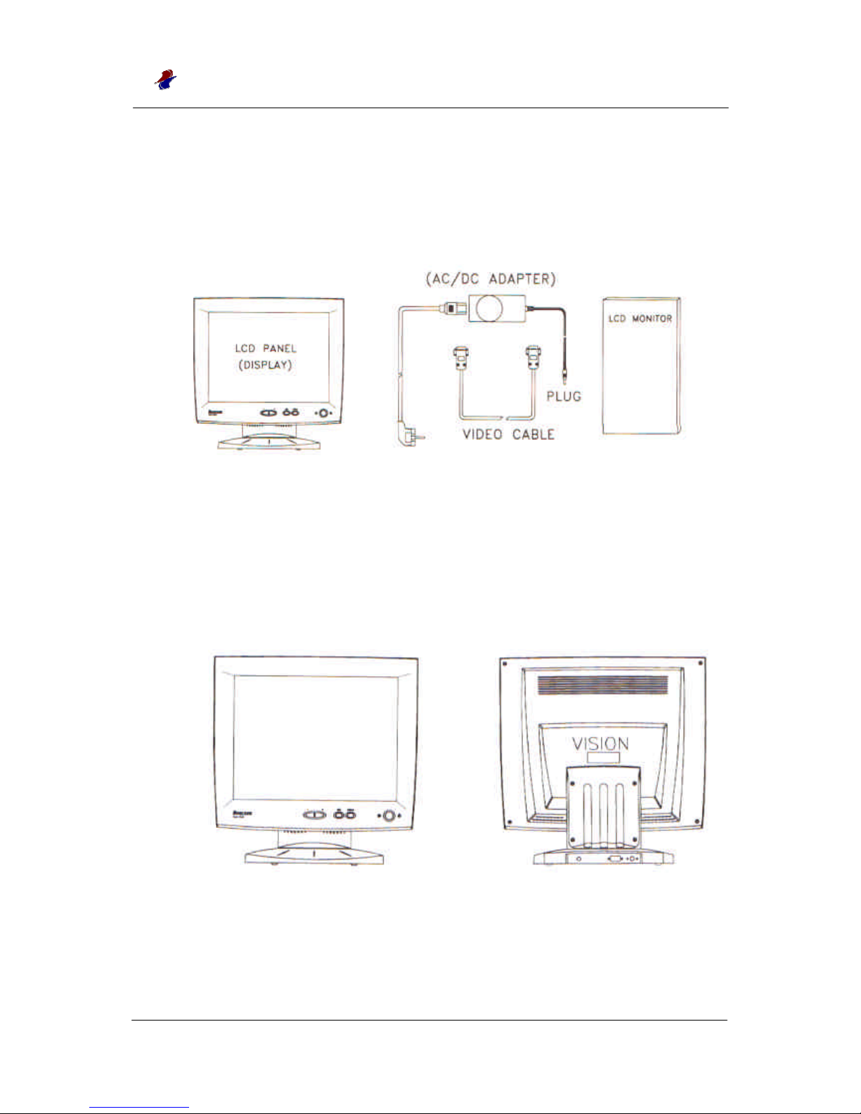
2. Components & Parts names
2-1) Components
Figure 2-1) : Components
2-2) Front & Rear View
Figure 2-2) Front View Figure 2-3) Rear View
Page 7

finecom
FLM-520 User’s Guide
- -
7
3. Installation
1) Connect the input plug to FLM-520 LCD monitor.
(Connect 15 pin RGB connector, for analogue RGB input, to FLM-312 as shown Figure
2-3).
2) Connect the 12V Adapter to FLM-520.
(When you turn on power switch, LED on the board will light Red, Green in turn and
then green will remain.)
3) Adjust parameters of OSD Menu by using External keypad.
(Automatic Configuration is convenient to use; When power on or screen mode changes,
optimized conditions are made automatically)
4) If there is something wrong with Video Cable or PC power is off, the message of “No
Sync” is displayed on the screen. When this condition continues 10 seconds, LED on the
board lights red and then the power of LCD panel is automatically cut off. Once Video
cable is connected or PC power turns on, LED lights Green and LCD panel power is
restored.
Page 8

finecom
FLM-520 User’s Guide
- -
8
4. Speaker
A speaker plug is ready at the rear of this LCD monitor. It is installed as follows;
1) Connect the PC Audio jack to FLM-520 Speaker plug.(1.5W 8 Ohm, Stereo)
2) Select Speaker volume at OSD initial Menu and then adjust the volume.
( After adjusting the volume, it shall be saved at the Initial Menu in order to keep
the setup volume when power on and off.
3) Decrease the volume when it is not used.
( 1.5 W Dual Amplifier is imbedded and it can bring noise when volume is too high)
Page 9
finecom
FLM-520 User’s Guide
- -
9
5. External Keypad
5-1) External Keypad
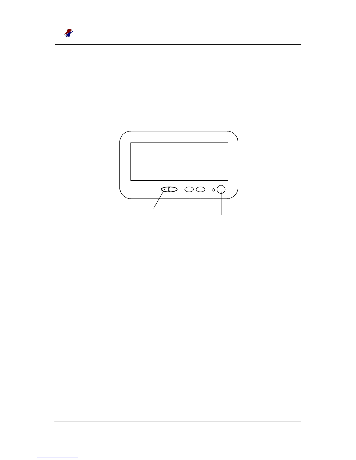
AT the rear left side External Keypad is ready for user’s interface, it is configured as
below :
Figure 5-1) External Keypad Block Diagram
If MENU button is pressed, the OSD MENU is displayed. The user can select the Menu
item by pushing SEL button, and then adjust the selected values and or move to below
Menu by using +(Right) and –(Left) buttons. Adjusted value shall be saved at OSD
Menu in order to keep it during power on and off.
5-2) Function of Push button
There are 4 buttons to do following functions.
MENU : To start or terminate Menu or move to upper Menu.
SEL (Down): To move to the item’s position to be selected.
LEFT (-): To decrease the selected parameter value or to move to below Menu.
RIGHT (+): To increase the selected parameter value or to move to below Menu.
- (Left)
+(Right)
Sel(Down)
Menu
LED
Power Switch
Page 10
finecom
FLM-520 User’s Guide
- -
10
6. OSD Overview
6-1) Power On Default Settings
FLM-520 devices are initialized during power-on to the last saved conditions.
During OSD all parameters are saved only when the user select SAVE at the Menu.,
In case the user exits the menus without selecting SAVE at Menu, the parameters are
applied only at present conditions and when Power on/off, it is returned to the last saved
value.
6-2) Value Controls
Many parameters value of Tree-type Menu can be adjusted by using the
+(Right) and –(Left) buttons. SEL button is pressed to move to the next item.
In order to move to the upper Menu, Menu button may be used or “Main Menu”
item is selected.
6-3) LED Active Source Indicator
When the LED lights Green, the monitor is ready to use normally.
When the LED lights Red, Power may be cut off because there is something wrong with
Video Input and or LCD panel power may be off when the user selected ‘Power Down’
at OSD Menu.
6-4) Warning Message
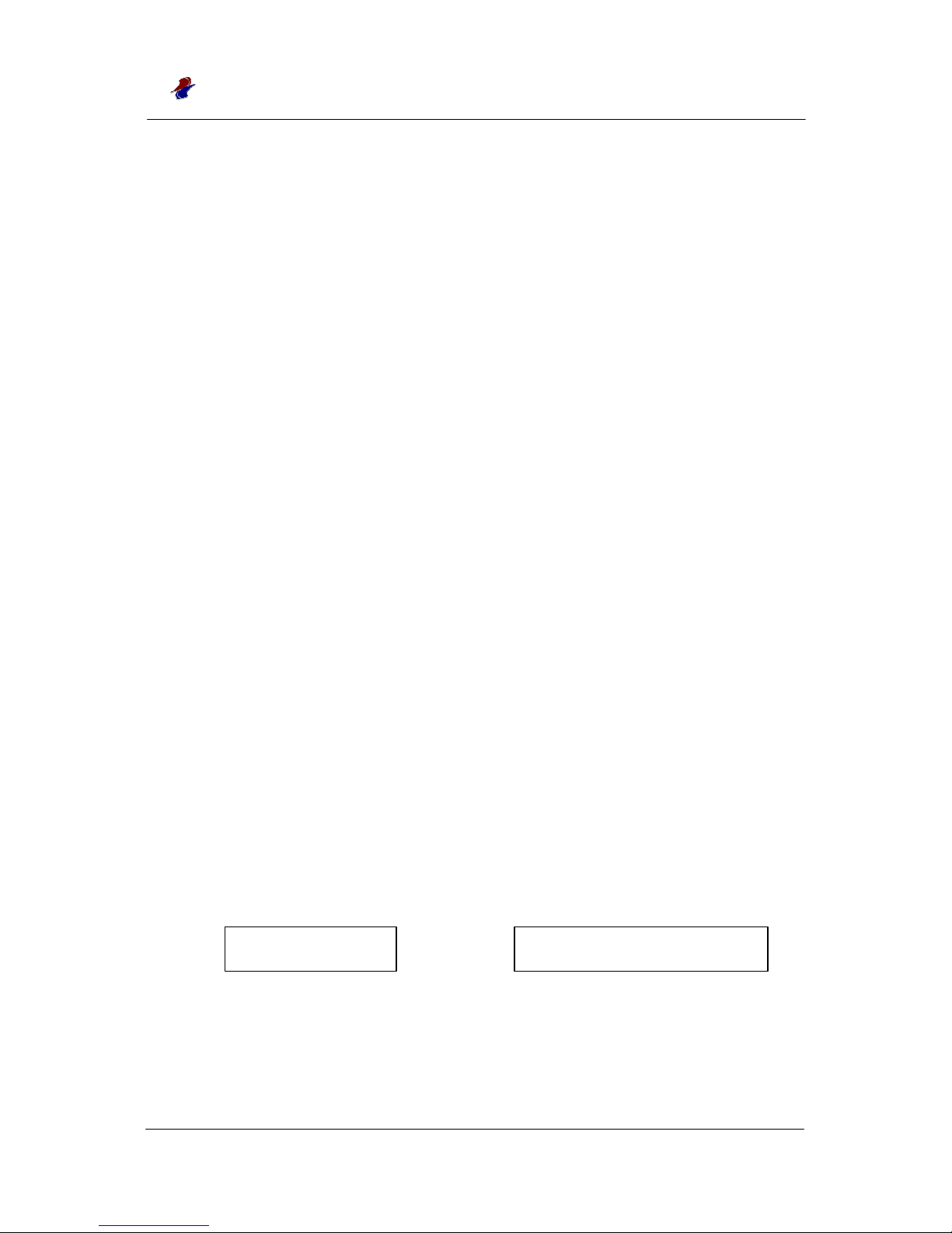
A warning message as in Figure 6-1 is displayed when the system detects that an RGB
Video cable is not connected to the FLM-520 monitor. The message is displayed for a
maximum of 10 seconds until the cable is connected.
A message in Figure 6-2 is displayed in case of not-supported Video Mode. Please refer
to Table 2 for supportable Video Modes.
Figure 6-1) No RGB Warning Message Figure 6-2 ) Unsupported Input Warning
Message
No Sync
Video Change Mode
Page 11
finecom
FLM-520 User’s Guide
- -
11
7. OSD Menu Items
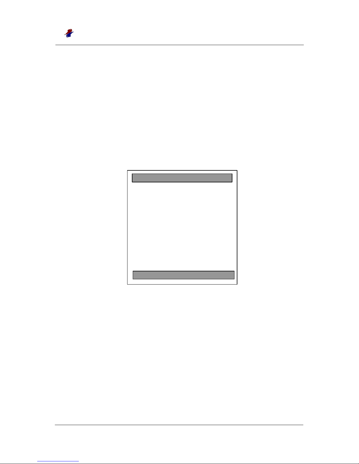
The OSD main Menu is displayed when the Menu keypad push button is pressed
when FLM-520 powered on, and inputs & outputs properly connected. The OSD
menu display is a combination of graphics and text as in Figure 7. The selected or
active menu item is indicated in blue color as below. In PC Graphic mode, the
bottom bar indicates the present input image resolution.
Sel(Down) button is used to move from item to item. The + and – keypad push
buttons are used to select the Menu or to change the value. The selected item is
highlighted. The Menu button is pressed to close the OSD Menu.
Figure 7) OSD Main Menu
There are 10 items within the main Menu.
RGB Menu: Adjusts color and brightness.
Geometry Menu: Adjusts the screen position.
Contrast Menu: Adjusts image contrast.
Info: Displays the product information.
Input Type: Selects Input Source.(Analog, Digital, NTSC/PAL)
Auto Config: Optimizes it into best condition automatically.
NVRAM Init : Initializes the saved value setup.
Power Down: Turn the power into power saving.
Revert: Turn into the last saved condition.
Save : Saves the setup value.
Geometry Menu
Contrast Menu
Info
Input Type
••••••••••••••
Auto Config
NVRAM Init
Power Down
Revert
Save
S 1024x768
R G B Menu
Page 12
finecom
FLM-520 User’s Guide
- -
12
7-1) RGB Menu
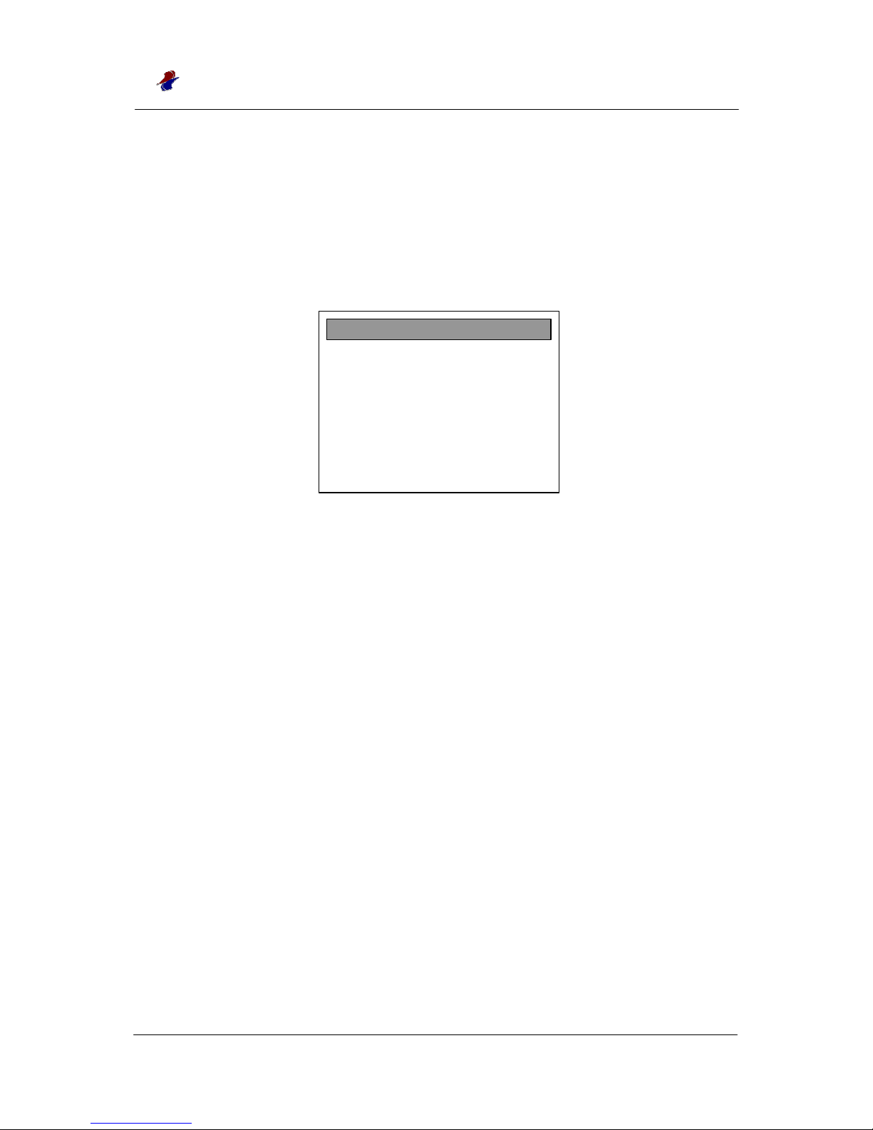
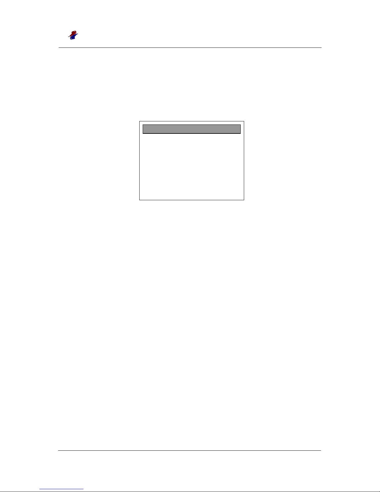
RGB item is used to adjust the image color and brightness. Indicated number
shows the present brightness value as Figure 7-1. The range of adjustment is
–127 to 127. The RGB value is adjusted according to the input selected.
Figure 7-1) Contrast Slider
Brightness
Adjusts the screen brightness by adjusting Red, Green and Blue in
total.
Red
Adjusts brightness of Red color by increasing or decreasing Red Color
Channel of PC Graphic.
Green
Adjusts brightness of Green color by increasing or decreasing
Green Color Channel of PC Graphic.
Blue
Adjusts brightness of Blue color by increasing or decreasing
Blue Color Channel of PC Graphic.
Color Temp
Adjusts Gamma table suitable for the PC. Range of adjustment is 0 to 6.
Sharpness
Adjusts the Graphic outline. Range of adjustment is 0 to 4.
Red 0
Green 0
Blue 0
Color Temp 3
Sharpness
Main Menu
Brightness
Page 13
finecom
FLM-520 User’s Guide
- -
13
7-2) Geometry Menu
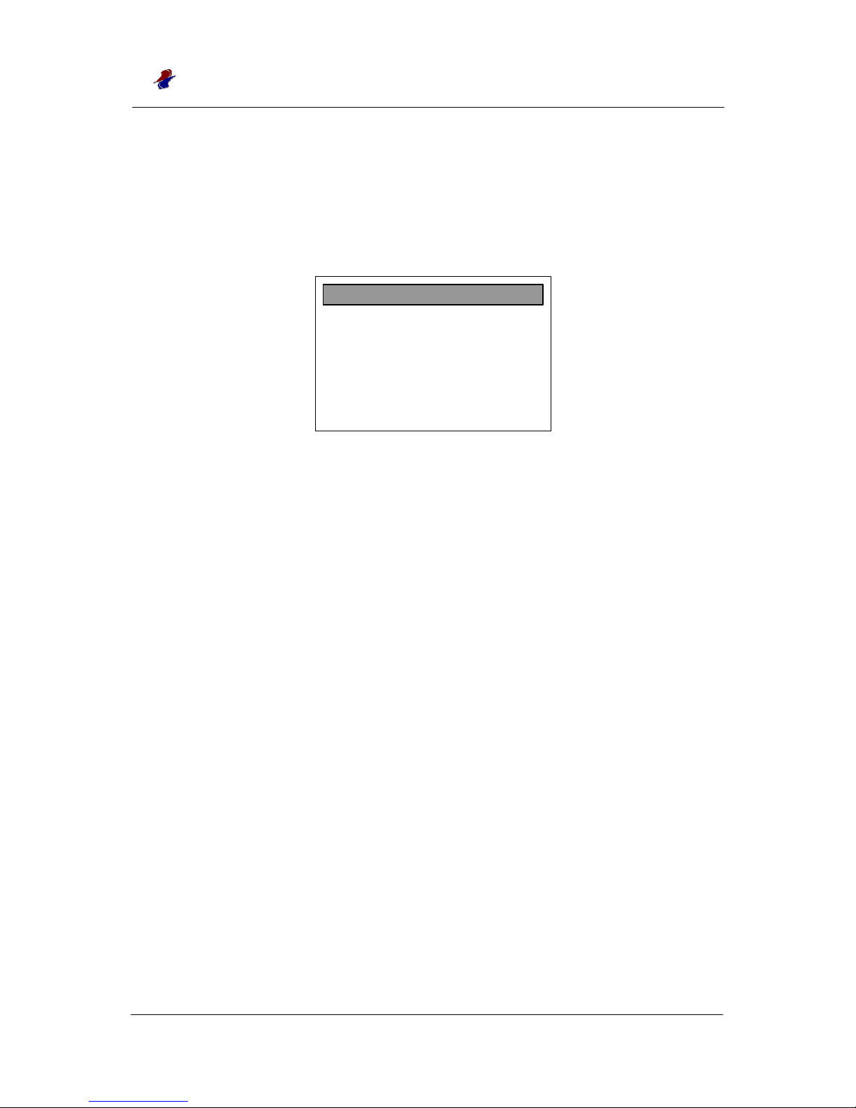
This Menu is used to adjust screen position of the monitor by adjusting Clock
(Pixel) numbers per a line or automatically.
Figure 7-2) Geometry Menu
Auto Adjustment
Adjusts automatically the position or size by searching for the optimized condition to
the PC Graphic.
H Position
H-Position is used for the user to manually adjust the image horizontal position,
the range of value adjustment is different according to Input Mode selected.
V Position
V-Position is used for the user to manually adjust the image vertical position, the
range of value adjustment is different dependent on Input Mode selected.
H Total
H-Total is used to adjust Clock(Pixel) numbers, the value can be changed according
to the PC screen.
Auto Phase
Auto Phase makes the screen optimized by adjusting ADC Sample Pixel Clock
according to the PC Graphic environment.
Delay
Setup the delay value of SCLK Clock. The range is 0 to 47.
H Position 0
V Position 0
H Total 0
Auto Phase
Delay 3
Main Menu
Auto Adjustment
Page 14
finecom
FLM-520 User’s Guide
- -
14
7-3) Contrast Menu
Contrast Menu is used to adjust image contrast. The range of adjustment can be
changed according to the screen Mode.
7-3) Contrast Menu
Auto Balance
Makes the image contrast optimized by searching for the PC Graphic
condition.
Contrast
Adjusts the screen contrast by adjusting Red, Green and Blue in total.
Red
Adjusts the Red color contrast by increasing or decreasing Red Color Channel
of the PC Graphic.
Green
Adjusts the Green color contrast by increasing or decreasing Green Color
Channel of the PC Graphic.
Blue
Adjusts the Blue color contrast by increasing or decreasing Blue Color
Channel of the PC Graphic.
Contrast
Red 0
Green 0
Blue 0
Main Menu
Auto Balance
Page 15
finecom
FLM-520 User’s Guide
- -
15
7-4) Info
Can check Firmware Version, Model number of FLM-520 LCD monitor.
Figure 7-4) Info
7-5) Input Type
Setups the Input Type.
Caution) Digital Input, NTSC/PAL are optional. Even in case the user did not choose the
option, Digital Input and NTSC/PAL are displayed in the OSD Menu but they are not
operating.
Figure 7-5) Input Type selection
Analog Input
Selects the Input Signal which has Red, Green and Blue Signals.
Digital Input
Selects Digital Input(TMDS method).
NTSC/PAL
Selects NTSC/PAL(Color TV receiver method) Input.
( NTSC : National Television System Committee, PAL : Phase Alternation by Line)
FLM-520
Version 1.x
Finecom Co., Ltd.
URL:www.finecom.co.kr
Digital Input
NTSC / PAL Input
Main Menu
Analog Input
Page 16

finecom
FLM-520 User’s Guide
- -
16
7-6) Auto Config
Makes the screen condition optimized by searching screen condition.
7-7) NVRAM Init
Initializes the saved value of FLM-520 NVRAM when the power turns off.
Even though you selected NVRAM, the present value is not changed.
7-8) Power Down
Changes Board LED to Red and cuts off the power of LCD panel.
To restore the power, press the external Keypad button.
7-9) Revert
This Menu is used to return to the last saved value. It is used to revert the last
saved value when the user changed the setup by mistake and or the user would
like to return to the last saved value.
7-10) Save
Saves the present setup into NVRAM.
Page 17

finecom
FLM-520 User’s Guide
- -
17
8. Installation of Windows Driver
FLM-520 provides Windows 95/98 Driver, which is recommended to
install for the case of “ screen is not displayed because video mode
not supported by FLM-520 is set”.
It is not necessary to inevitably install FLM-520 Windows driver. But
when installed, supported resolution and revival frequency(screen
return/frequency) are indicated in the list. Accordingly, the user
cannot set resolution and frequency not supported by this device
so that the monitor’s non-operation by the user ’s mistake can not happen.
Installation method
1) Insert the provided Windows Driver diskette into the floppy drive.
2) When the program is executed, click “driver Installation”.
3) When driver is copied, system rebooting will finish driver
installation.
For reference, in case not supported Mode has already been installed, it is possible to install by
booting Windows safe Mode.
Page 18

finecom
FLM-520 User’s Guide
- -
18
9. Specifications
• LCD panel: TFT
• Viewable area: 15”
• Resolution : 1024×768
• Viewing Angle: R/L: 50/50, Up/Down: 25/50
• Pixel pitch: 0.297 x 0.297 mm
• Display color: 262,144 Colors
• Brightness: 200 cd/mxm
• Contrast ratio: 200
• Response time: 40 ms
• Input video signal: VGA Compatible Analog RGB
• Horizontal frequency: 31~60KHz
• Vertical frequency: 56~75Hz
• Screen expansion: Advanced Image Magnification Zoom Scaler
• Compatibility: IBM VGA, SVGA, XGA
• OSD Control: Brightness, Contrast, Color, Position, Phase
• Speaker: 1.5Watt x 2 Speakers
• Power Source: 12V AC-DC Adapter(Input 100~240V AC, 50~60Hz)
• Power consumption: 40W Max
• Dimension (WxHxD): 385(W) x 329(H) x 90(D) mm
• Weight: 5.0 kg
• Temperature: 1~50 °C
• Humidity: 90%
Page 19
finecom
FLM-520 User’s Guide
- -
19
10. Problems and Check Points
* No Image shows up: - Check if the power indicator is on.
- Check if you turned on the power S/W.
- See that Power cable is connected well.
- Ensure any pin of connectors are not broken or crooked.
* Image not centered, not stable: Please refer to OSD functions.
* Warning: Please do not open the Monitor, it may cause serious problem.
When you or your supplier cannot solve the problem, please contact
the service personnel at the maker.
Table 1 : Analog RGB Input Port Signal Description
Pin No. Pin Name Logic Description
1 RED Analog Red Input Signal
2 GRN “ Green “
3 BLU “ Blue “
13 HSYNC TTL Horizontal Sync
14 VSYNC “ Vertical “
12 Monitor ID bit 1 “ DDC SDA
15 Monitor ID bit 3 “ DDC SCL
9 +5V-DDC1 Power +5V From Graphic Card,
Not Used
5,6,7,8,10 GND Grond
4,11, 9 No Connect Not Used
Page 20
finecom
FLM-520 User’s Guide
- -
20
Table 2: Supported RGB PC Graphics Input Formats
VESA MODES
Horizontal2 Vertical2
Mode Resolution Nominal
Total
Nominal
Frequency
+/- 5kHz
Sync
Polarity
Nominal
Frequency
+/- 1 Hz
Sync
Polarity
Nominal
Pixel
Clock
(MHz)
640x480@60Hz 800x525 31.649 N 59.940 N 25.175
VGA(6)7
VGA(8)
VGA(9)
640x480@72Hz
640x480@75Hz
832x520
840x500
37.861
37.500
N
N
72.809
75.000
N
N
31.500
31.500
800x600@56 Hz 1024x625 35.156 N/P 56.250 N/P 36.000
800x600@60 Hz 1056x628 37.879 P 60.317 P 40.000
800x600@72Hz 1040x666 48.077 P 72.188 P 50.000
SVGA(11)
SVGA(12)7
SVGA(13)
SVGA(14)
800x600@75Hz 1056x625 46.875 P 75.000 P 49.500
1024x768@60Hz 1344x806 48.363 N 60.004 N 65.000
1024x768@70Hz 1328x806 56.476 N 70.069 N 75.000
XGA(17)5
XGA(18)
XGA(19)
1024x768@75Hz 1312x800 60.023 P 75.029 P 78.750
IBM MODES
EGA(1)3 640x350@70Hz 800x449 31.469 P 70.086 N 25.175
CGA(23)4 640x400@70Hz 800x449 31.469 N 70.086 P 25.175
EGA(25)3 720x350@70Hz 900x449 31.469 P 70.086 N 28.322
DOS(4)4 720x400@70Hz 900x449 31.469 N 70.086 P 28.322
XGA(24) 1024x768@72Hz 1304x798 57.515 P 72.1 P 75.000
 Loading...