

Page 1
User Manual
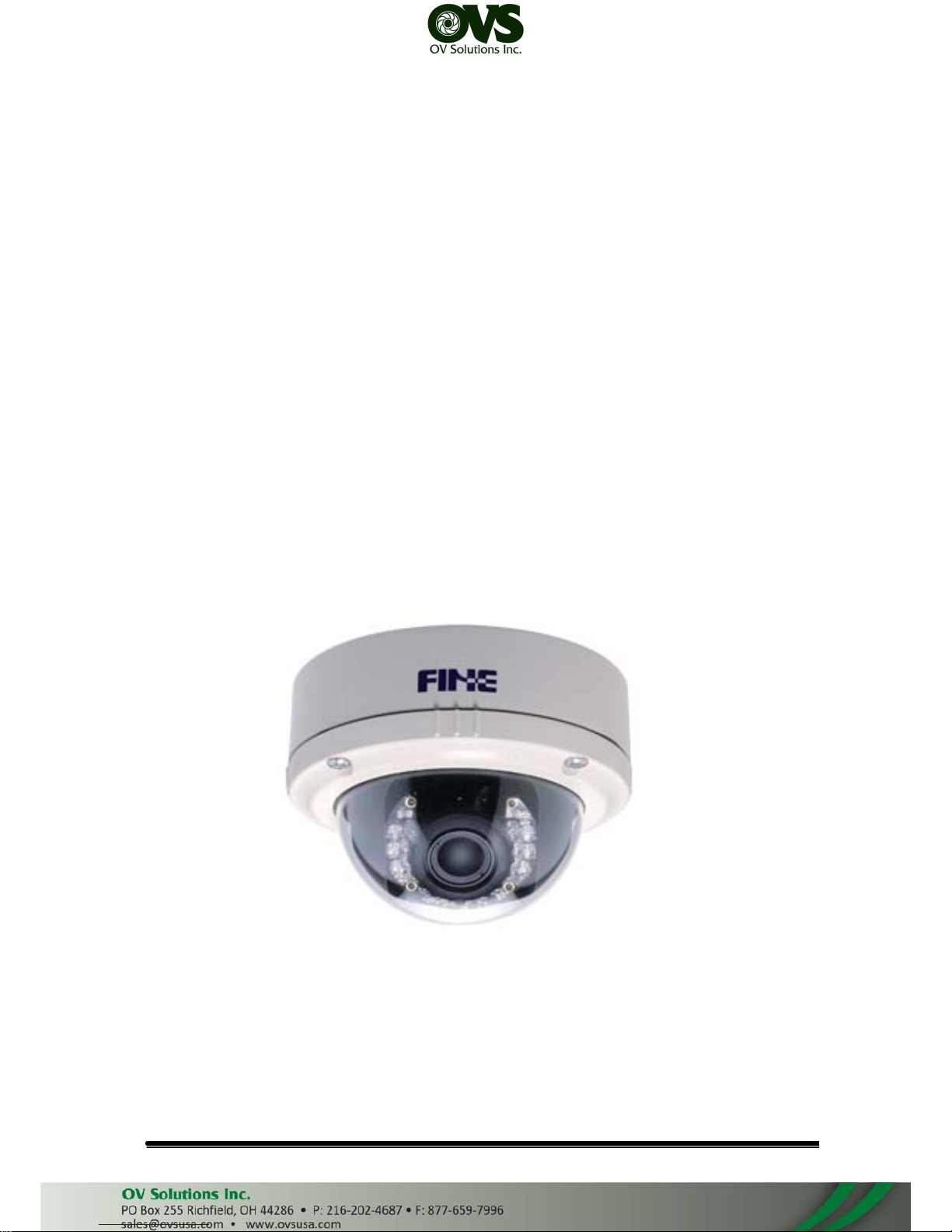
3-AXIS VANDAL DOME
IP CAMERA
User Manual
Page 2

WARINGS
TO REDUCE THE RISK OF FIRE OR ELECTRIC SHOCK, DO NOT EXPOSE THIS
PRODUCT TO RAIN OR MOISTURE.
DO NOT INSERT ANY METALLIC OBJECT THROUGH VENTILATION GRILLS.
CAUTION
CAUTION
RISK OF ELECTRIC SHOCK
DO NOT OPEN
CAUTION: TO REDUCE THE RISK OF ELECTRIC SHOCK.
DO NOT REMOVE COVER (OR BACK).
NO USER-SERVICEABLE PARTS INSIDE.
REFER SERVICING TO QUALIFIED SERVICE PERSONNEL.
COPYRIGHT
THE TRADEMARKS MENTIONED IN THE MANUAL ARE LEGALLY REGISTERED
TO THEIR RESPECTIVE COMPANIES.
User Manual
Page 3

CONTENT
I. Preface 4
II. Product Specifications
4
III. Produt Intallation
7
A. MONITOR SETTING 7
B. HARDWARE INSTALLATION 8
C. IP Assignment 10
D. Install ActiveX control 12
E. Live Video 14
IV. IP Camera Configuration 16
A. System 17
B. Network 20
C. A/V Setting 29
D. Event List 34
V. Network Configuration 37
VI. I/O Configuration 38
VII. Factory Default 41
VIII. Package contents
41
IX. Appendix
42
V1.0_120416
User Manual
Page 4

I. Preface
II.
This IP Camera is a IP Dome camera. It has the web server built in. User
can view real-time video via IE browser. IP Camera supports simultaneously
H.264, Motion JPEG & MPEG4 video compression and dual streaming which
provides smooth and high video quality. The Pan/Tilt/Zoom function can be
controlled remotely. The video can be stored in the SD card, and playback
remotely. With user friendly interface, it is an easy-to-use IP camera which is
designed for security application.
Product Specifications
Main Features:
• Full HD 1080P@30fps real time
• 1/2.7” 2Megapixel CMOS Sensor
• Digital Noise Reduction
• Digital Wide Dynamic Range
• Shutter Speed adjustion
• Sense Up adjustion
• Day&Night Switch time control manully
• IR-Cut filter (Option)
• IR Distance 15M
• Vandal proof
• Power over Ethernet available
• H.264/ M-JPEG / MPEG4 compression
• Micro SD card backup
• Support iPhone/Android/Mac
• Triple Streaming
• SDK for Software Integration
Specifications
Hardware
CPU
ARM Cortex A9
RAM
256MB
Flash
16MB
Image sensor 1/2.7” 2Megapixel CMOS sensor
User Manual
Page 5
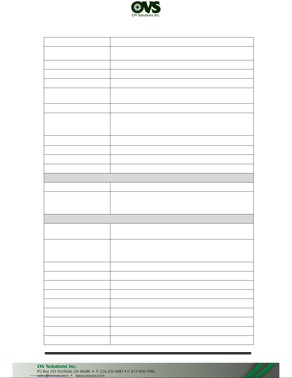
Lens Type Varifocus 3–9 mm MggaPixel Lens , F1.4
Sensitivity
Color : 0.1Lux AGC ON
B / W: 0.05 Lux AGC ON
Support DC IRIS Yes
Shutter Time Indoor, Outdoor, 1/30 ~ 1/1000
ICR Mechanism IR cut Filter (optional)
LED
Built-in 18 units IR LED
IR Distance-15M
I/O 1 Alarm in / 1 Relay out
Audio G.711(64K) and G.726(32K,24K) audio compression
Input : External Mic in
Output: External Audio out
Power over Ethernet Yes
Operating Temperature -10°C ~ 45°C
Dimensions 126mm (W) x 126mm (L) x 100mm (D)
Weight 1300 g
Network
Ethernet 10/ 100 Base-T
Network Protocol HTTP, HTTPS, SNMP, QoS/DSCP, Access list, IEEE
802.1X, RTSP, TCP/ IP, UDP, SMTP, FTP, PPPoE, DHCP,
DDNS, NTP, UPnP, 3GPP, SAMBA, Bonjour, IPv4, IPv6
System
Video Resolution
1920x1080@30fps, 1280x720@30fps, ,640x480@30fps,
320x240@30fps, 176x144@30fps
Video Adjust Brightness, Contrast, Hue, Saturation, Sharpness, Shutter
Speed, AGC, Sense-Up, D-WDR,Flip, Mirror, Noise
reduction, Exposure, Day&Night
Triple Streaming Yes
Image snapshot Yes
Full screen monitoring Yes
Privacy Mask Yes, 3 different areas
Compression format H.264/ M-JPEG/ MPEG4
Video bitrates adjust CBR, VBR
Motion Detection Yes, 3 different areas
Triggered action Mail, FTP, Save to SD card, Relay out, SAMBA
Pre/ Post alarm Yes, configurable
User Manual
Page 6
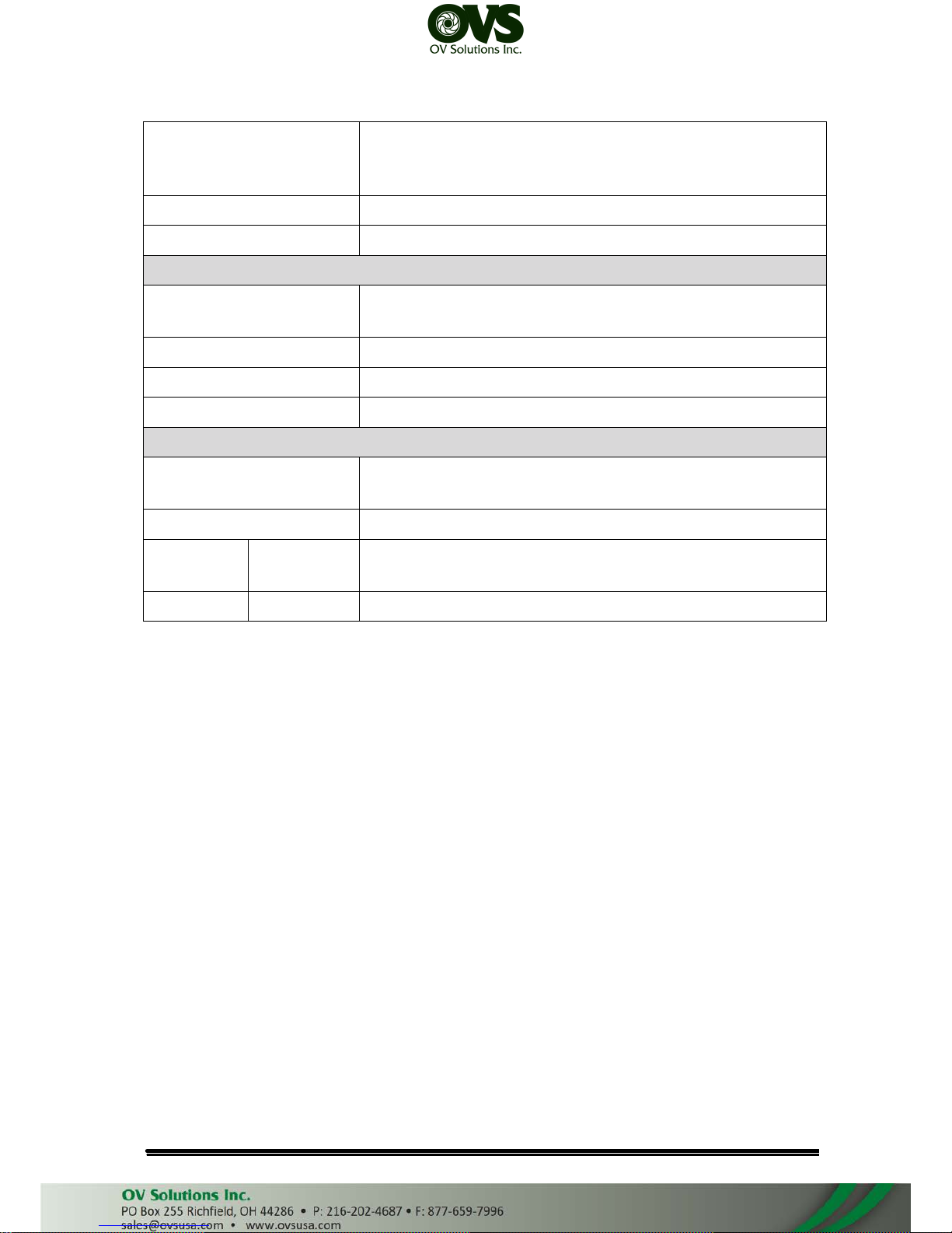
Security
Password protection, IP address filtering, HTTPS
encrypted data transmission, 802.1X port-based
authentication for network protection, QoS/DSCP
Firmware upgrade HTTP mode, can be upgraded remotely
Simultaneous connection Up to 10
SD card management
Recording trigger
Motion Detection, IP check, Network break down (wire
only), Schedule, Alarm in
Video format AVI, JPEG
Video playback Yes
Delete files Yes
Client System requirement
OS
Windows 7, 2000, XP, 2003, Microsoft IE 6.0 or above,
Chrome, Safari, Firefox
Mobile Support iOS 4.3 or above, Android 1.6 or above.
Hardware Suggested Intel Dual Core 2.53G,RAM: 1024MB, Graphic card:
128MB
Minimum Intel-C 2.8G, RAM: 512MB, Graphic card: 64MB
User Manual
Page 7
III.
Produt Intallation
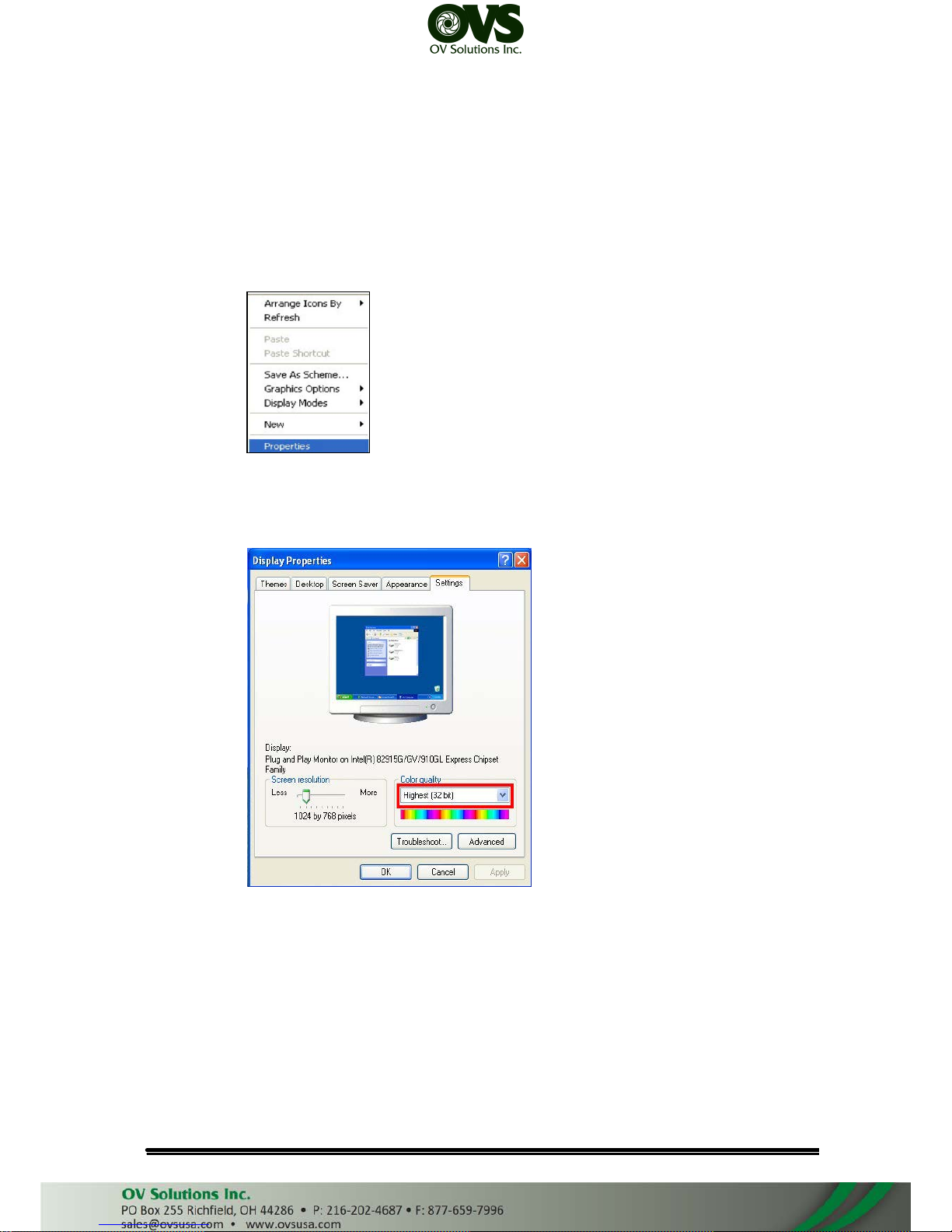
A. MONITOR SETTING
1. Right-Click on the desktop. Select “ Properties”
2. Change color quality to highest (32bit).
User Manual
Page 8
B. HARDWARE INSTALLATION
1. Connect power adaptor first.
2. Connect IP Camera to PC or network
3. Set up the network configurations according to the network environment. For
further explanation, please refer to chapter V: “Network Configuration for IP
Camera”.
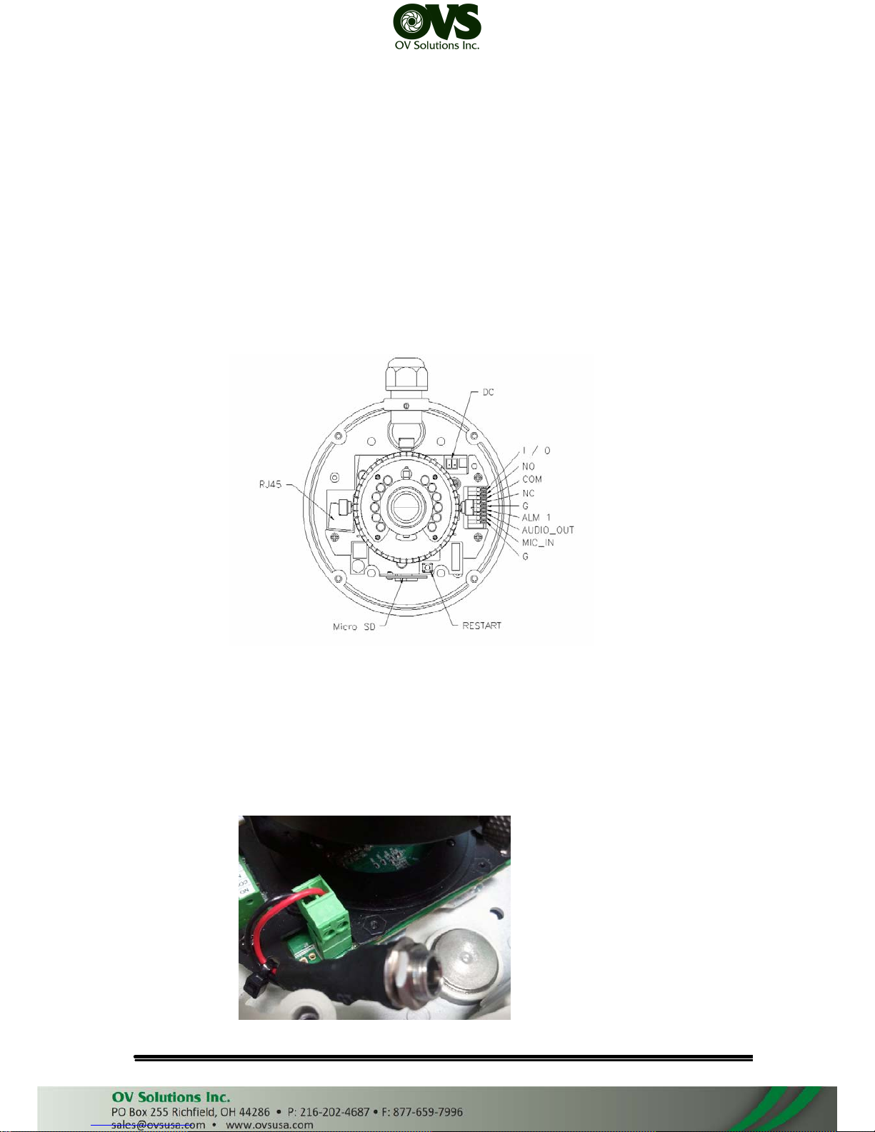
4. IP Camera Instruction
Remove the dome cover, and you will see the structure as below.
5. Connector Instruction
Connect the camera with power and Internet as the picture above. The
following picture shows a DC 12V connector for adapter jack plug. About I/
O setting, please refer to chapter VI in User Manual: "I/O Configuration" for
detail.
User Manual
Page 9
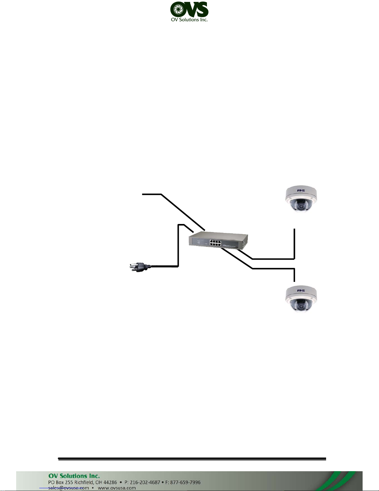
6. PoE ( Power Over Ethernet)(Optional) 802.3at, 30.0W PoE Switch is
recommended
Power over Ethernet (PoE) is a technology that integrates power into a
standard LAN infrastructure. It enables power to be provided to the network
device, such as an IP phone or a network camera, using the same cable as
that used for network connection. It eliminates the need for power outlets at
the camera locations and enables easier application of uninterruptible power
supplies (UPS) to ensure 24 hours a day, 7 days a week operation.
Ethernet
PoE
Switch
PoE IP Camera
PoE IP Camera
Ethernet Cable
Ethernet Cable
User Manual
Page 10
C. IP Assignment
1. Use the software, “IP Installer” to assign the IP address of IP Camera. The
software is in the attached CD.
2. There are two languages for the IP installer
a. IPInstallerCht.exe: Chinese version
b. IPInstallerEng.exe: English version
3. There are 3 kinds of IP configuration.
a. Fixed IP (Public IP or Virtual IP)
b. DHCP (Dynamic IP)
c. Dial-up (PPPoE)
4. Execute IP Installer
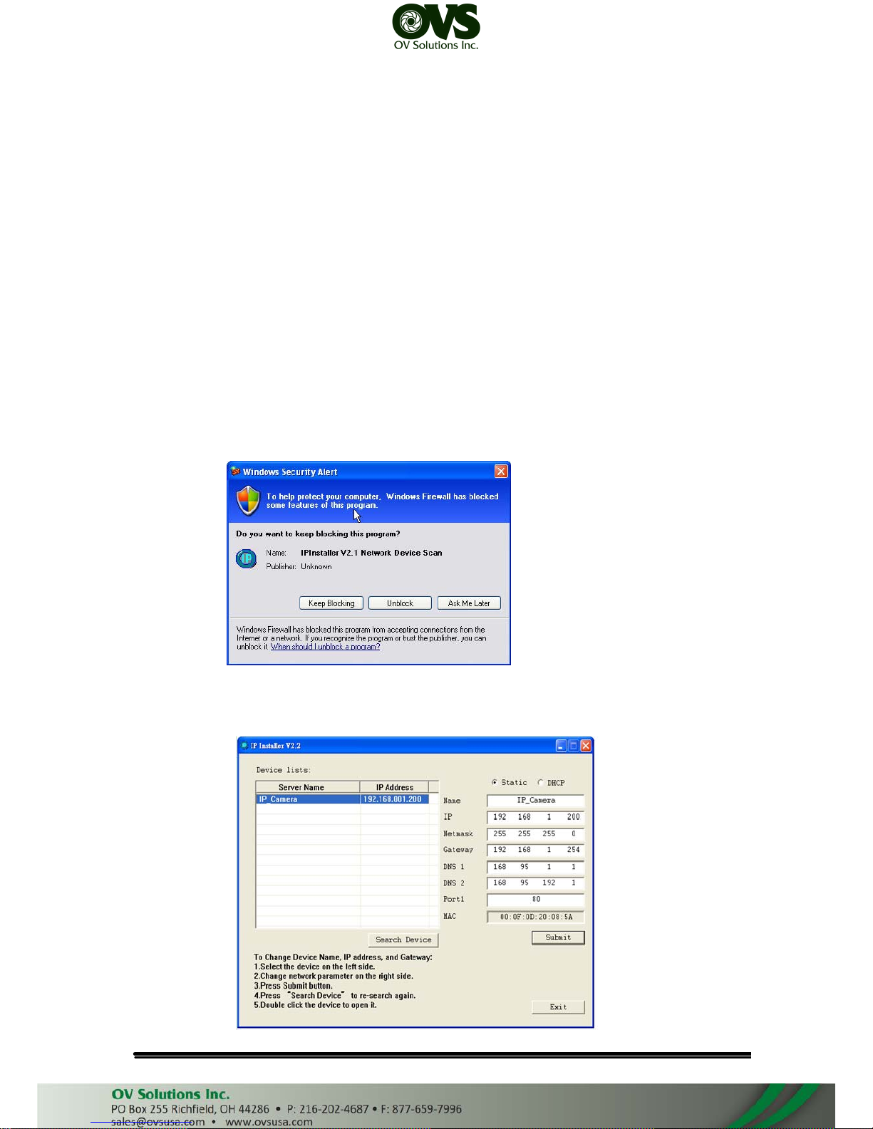
5. For Windows XP SP2 user, it may popup the following message box. Please
click “Unblock”.
6. IP Installer configuration:
User Manual
Page 11
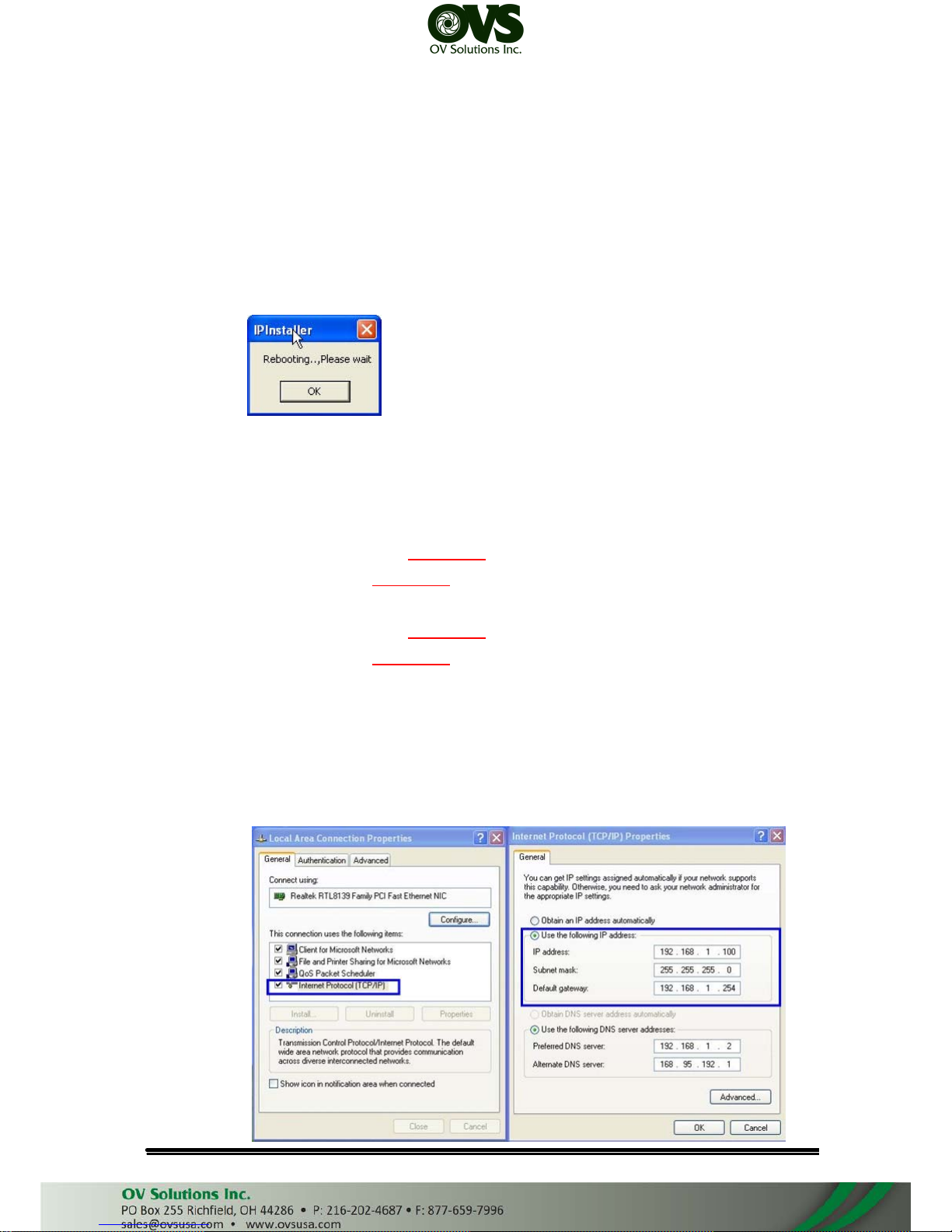
7. IP Installer will search all IP Cameras connected on Lan. The user can click
“Search Device” to search again.
8. Click one of the IP Camera listed on the left side. The network configuration
of this IP camera will show on the right side. You may change the “name”
of the IP Camera to your preference (eg: Office, warehouse). Change the
parameter and click “Submit” then click “OK”. It will apply the change and
reboot the Device.
9. Please make sure the subnet of PC IP address and IP CAM IP address are
the same.
The same Subnet:
IP CAM IP address: 192.168.1.200
PC IP address: 192.168.1.100
Different Subnets:
IP CAM IP address: 192.168.2.200
PC IP address: 192.168.1.100
To Change PC IP address:
Control Panel→Network Connections→ Local Area Connection Properties→
Internet Protocol (TCP/IP) → Properties
Please make sure your IP Camera and PC have the same Subnet. If not,
please change IP Camera subnet or PC IP subnet accordingly.
User Manual
Page 12
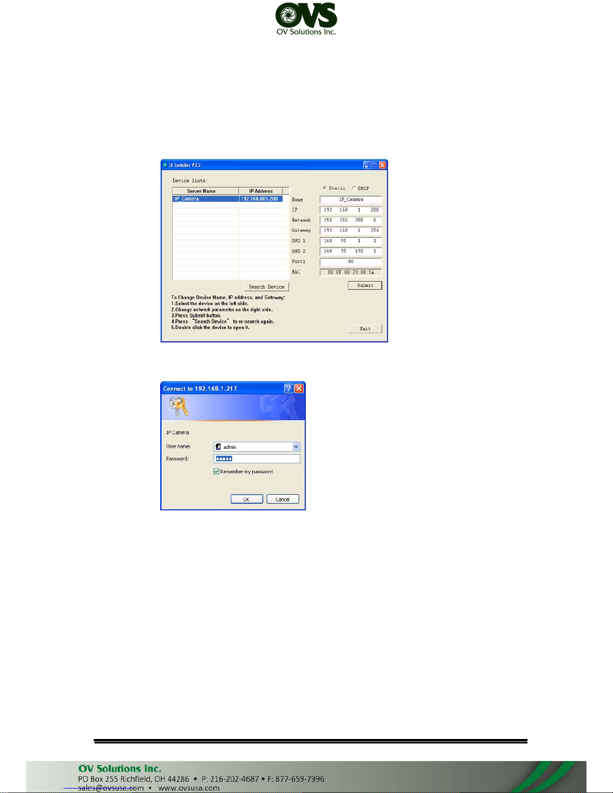
10. A quick way to access remote monitoring is to left-click the mouse twice on
a selected IP Camera listed on “Device list” of IP Installer. An IE browser will
be opened.
11. Then, please key in the default “user name: admin” and “password: admin”.
D. Install ActiveX control
For the first time to view the camera video via IE, it will ask you to install
the ActiveX component.
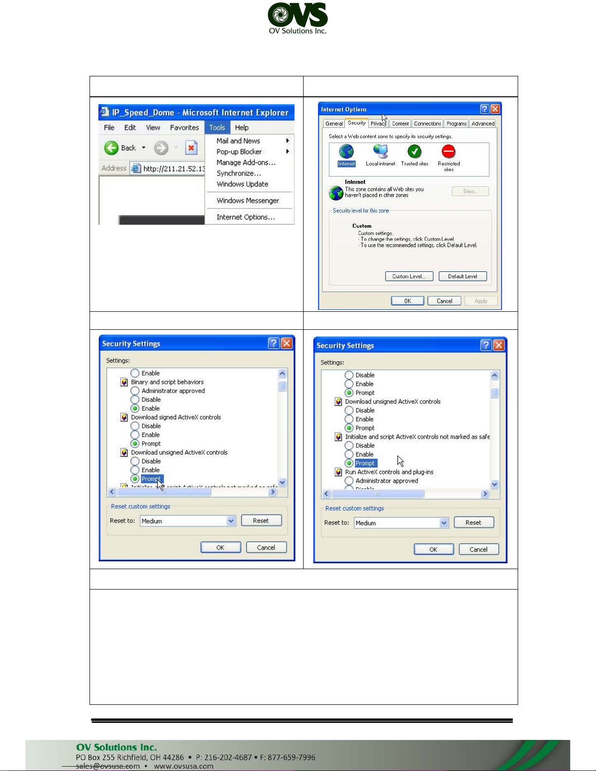
If the installation failed, please check the security setting for the IE browser.
1. IE→Tools → Internet Options… → Security Tab → Custom Level… →
Security Settings → Download unsigned ActiveX controls→ Select “Enable”
or Prompt.
2. IE → Tools → Internet Options… → Security Tab → Custom Level…
→Initialize and script ActiveX controls not marked as safe → Select “Enable”
or Prompt.
User Manual
Page 13
1 2
3 4
5
When popup the following dialogue box, click “Yes”.
User Manual
Page 14
E. Live Video
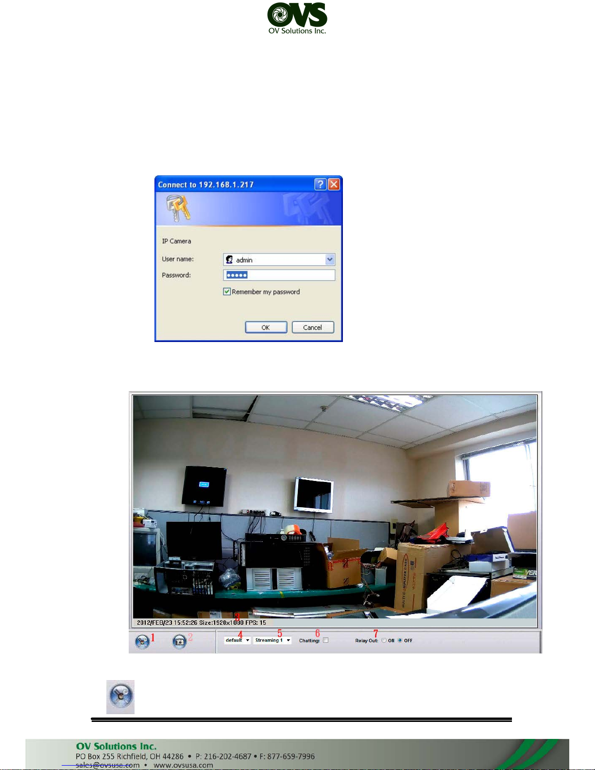
Start an IE browser, type the IP address of the IP camera in the address field.
It will show the following dialogue box. Key-in the user name and password. The
default user name and password are “admin” and “admin”.
When the IP Camera is connected successfully, it shows the following
program interface.
1. :Get into the administration page
User Manual
Page 15
2. :Video Snapshot
3. Show system time, video resolution, and video refreshing rate.
4. Adjust image, 1/2x, 1x, 2x.
5. Select video streaming source. (When streaming 2 setting in『Video Setting』 is closed, this
function will not display.)
6. IP Camera supports 2-way audio. Click the “Chatting” check box. Then you can use
microphone which connects to the PC to talk to server side, which is IP Camera side
7. Control the relay output which is connected to this camera.
Double-click the video to switch to full screen view. Press “Esc” or double-
click the video again back to normal mode.
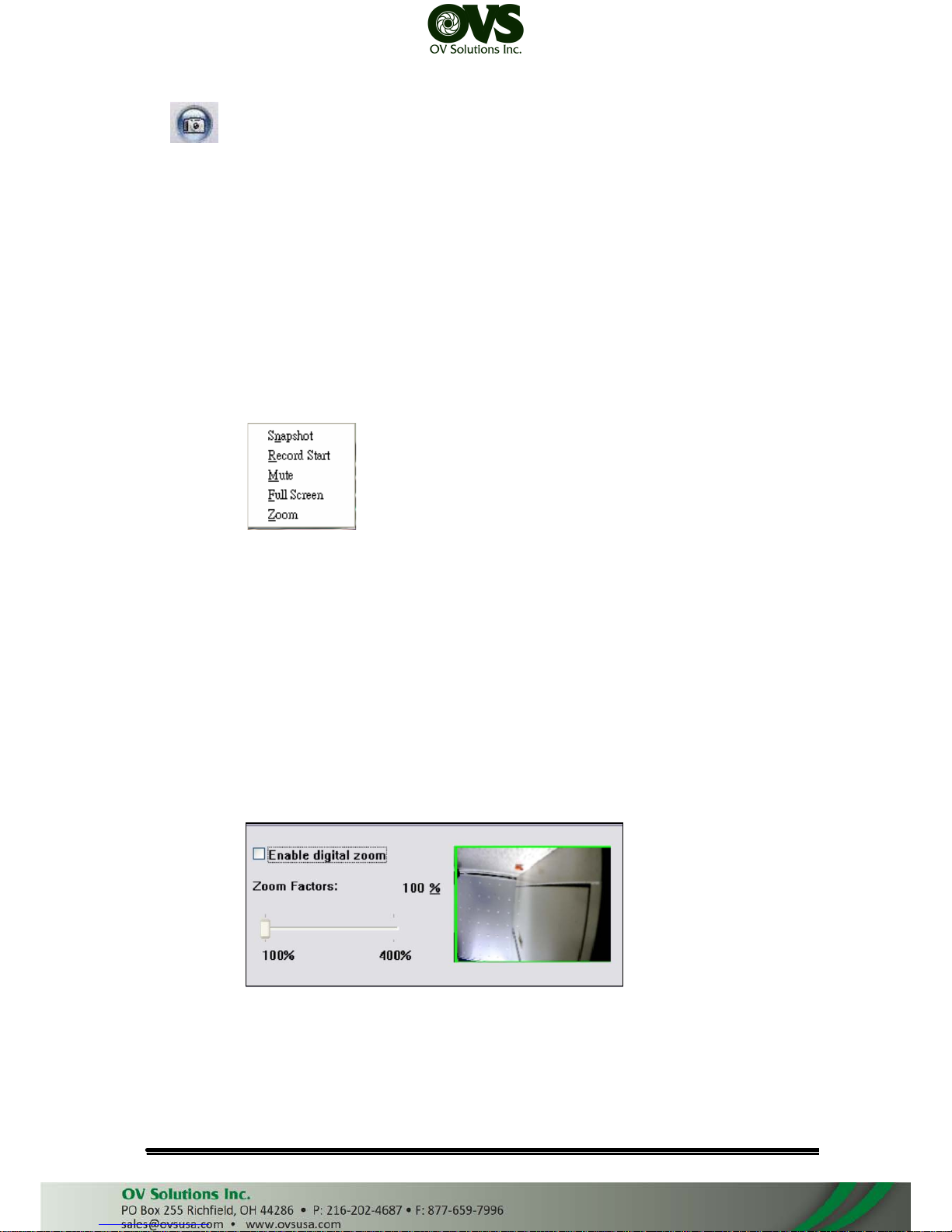
Right-Click the mouse on the video, it will show a pop-up menu.
1. Snapshot: Save a JPEG picture
2. Record Start: Record the video in the local PC. It will ask you where to save
the video. To stop recording, right-click the mouse again. Select “Record
Stop”. The video format is AVI. Use Microsoft Media Player to play the
recorded file.
3. Mute: Turn of the audio. Click again to turn on it.
4. Full Screen: Full-screen mode.
5. ZOOM: Enable zoom-in and zoom-out functions. Select “Enable digital zoom”
option first within the pop-up dialogue box and then drag and drop the bar to
adjust the zoom factors.
User Manual
Page 16
IV.
IP Camera Configuration
Click to get into the administration page. Click to go back to the live video
page.
User Manual
Page 17
A. System
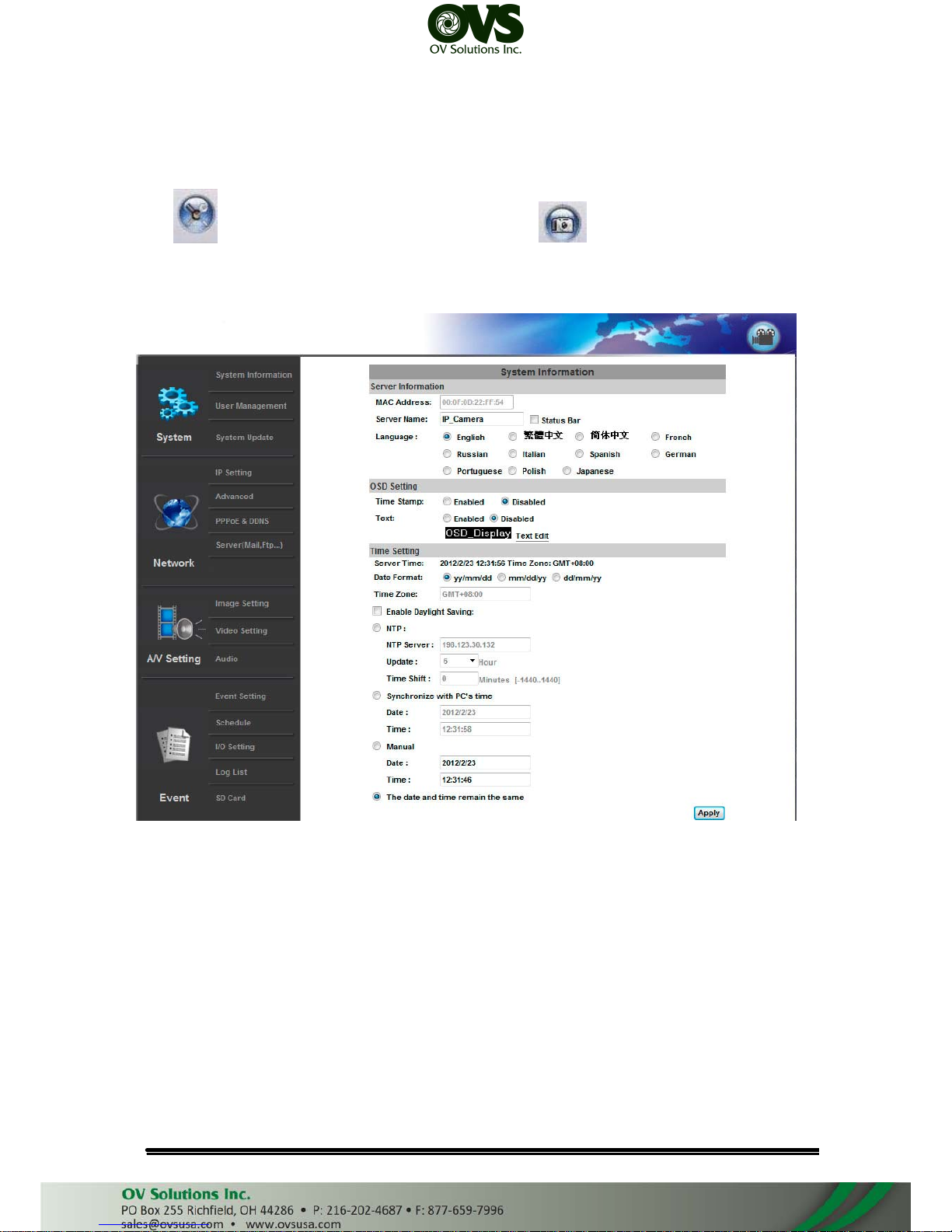
1. System Information
a. Server Information: Set up the camera name, select language, and set up
the camera time.
(i)
(ii)
Server Name: This is the Camera name. This name will show on the IP
Installer.
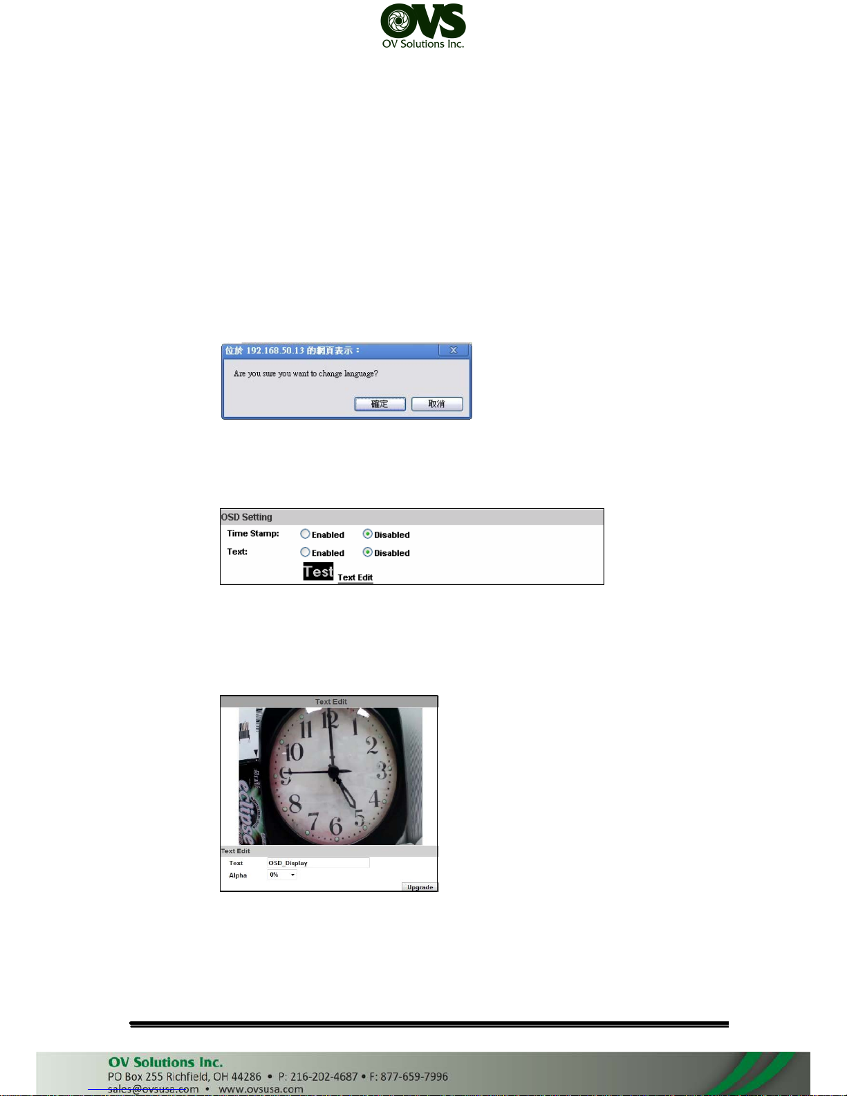
Select language: There are English, Traditional Chinese, and Simplified
Chinese to select. When change, it will show the following dialogue box
for the confirmation of changing language.
b. OSD Setting: Select a position where date & time stamp / text showing on
screen.
Moreover, click Text Edit can entry to adjust the OSD contents which is
Alpha of text. Finally, click Upgrade button to reserve the setting.
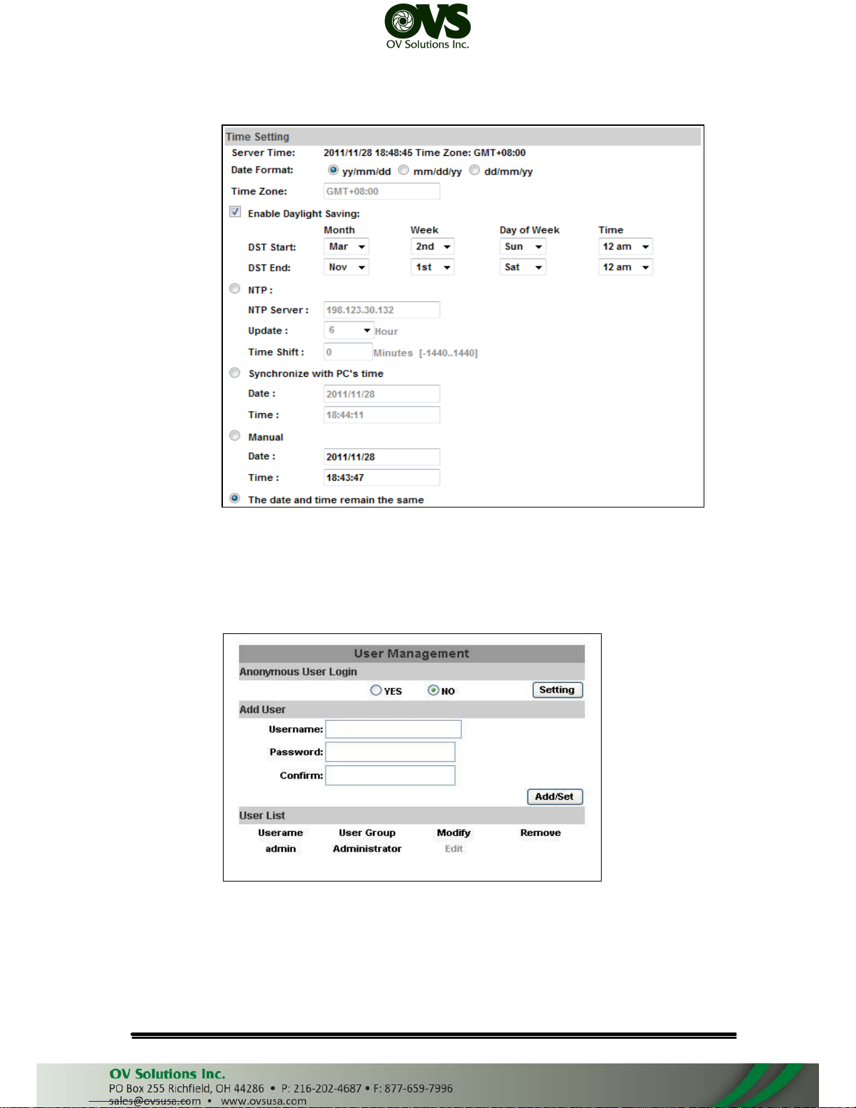
c. Server time setting: Select options to set up time - “NTP”, “Synchronize
with PC’s time”, “Manual”, “The date and time remain the same”.
User Manual
Page 18
2. User Management
IP CAMERA supports three different users, administrator, general user, and
anonymous user.
a. Anonymous User Login:
Yes:Allow anonymous login
No:Need user name & password to access this IP camera
b. Add user:
Type the user name and password, then click “Add/Set”.
User Manual
Page 19
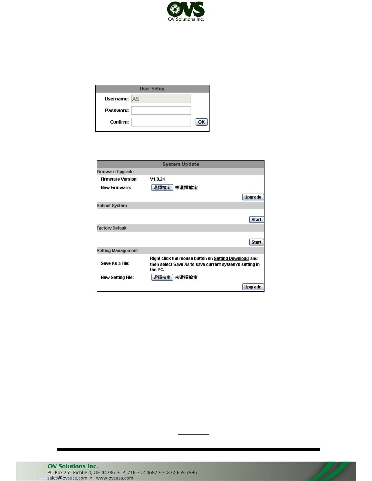
c. Click “edit” or “delete” in the user list to modify them. The system will ask
you to key in the password in the pop-up window before you edit the user
information.
3. System update:
a. To update the firmware online, click “Browse…” to select the firmware.
Then click “Upgrade” to proceed.
b. Reboot system:re-start the IP camera
c. Factory default:delete all the settings in this IP camera.
d. Setting Management:User may download the current setting to PC, or
upgrade from previous saved setting.
(i)
(ii)
Setting download:
Right-click the mouse button on Setting Download → Select “Save
AS…” to save current IP CAM setting in PC → Select saving directory
→ Save
Upgrade from previous setting:
Browse → search previous setting → open → upgrade → Setting
update confirm → click index.html. to return to main page
User Manual
Page 20
B. Network
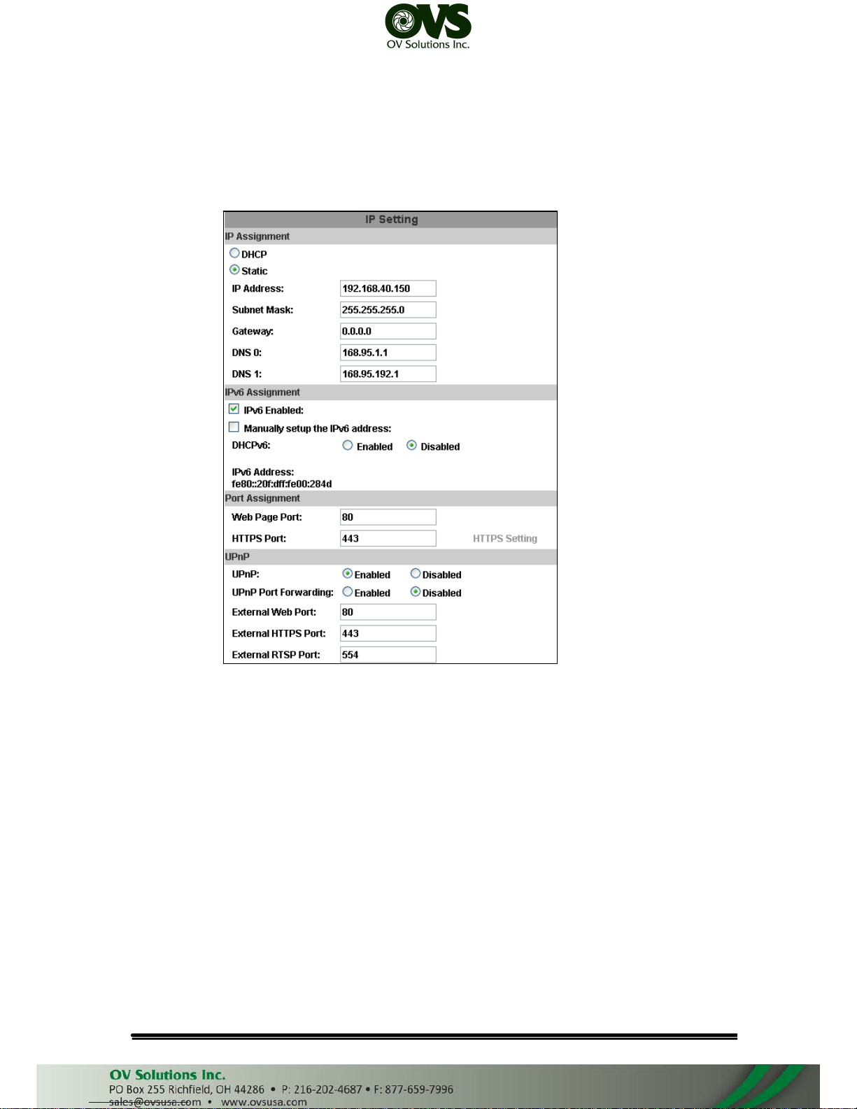
1. IP Setting
IP Camera supports DHCP and static IP.
a. IP Assignment
(i)
(ii)
DHCP: Using DHCP, IP CAMERA will get all the network parameters
automatically.
Static IP: Please type in IP address, subnet mask, gateway, and DNS
manually.
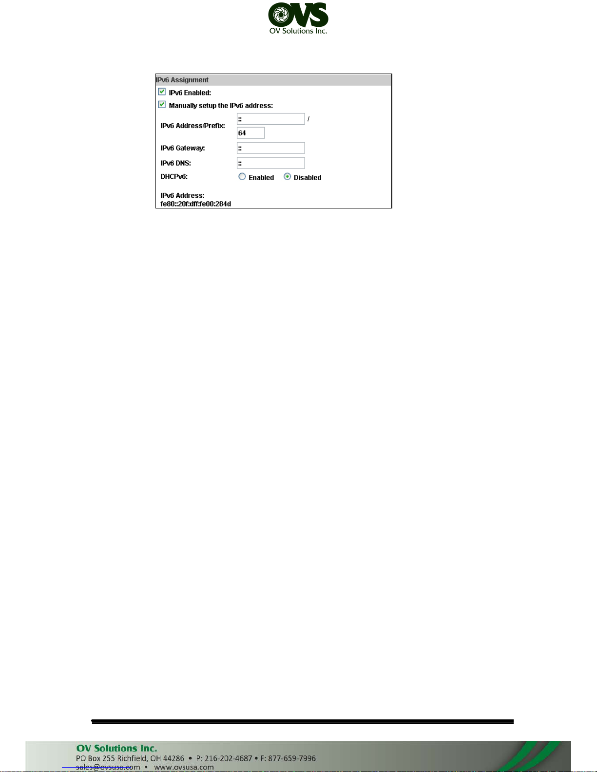
b. IPv6 Assignment: IPv6 is a newer numbering system that provides a much
larger address pool than IPv4, which accounts for most of today’s Internet
traffic. You can set up IPv6 manually by key in Address, Gateway, and
DNS, or enable DHCP to assign the IP automatically.
User Manual
Page 21
c. Port assignment:
(i)
(ii)
Web Page Port: setup web page connecting port and video transmitting
port (Default: 80)
HTTP Port:setup HTTPS connecting port (Default:443)
d. UPnP (Universal Plug and play):
This IP camera supports UPnP, If this service is enabled on your
computer, the camera will automatically be detected and a new icon will be
added to “My Network Places.”
(i)
(ii)
UPnP Port Forwarding:
Enable UPnP Port Forwarding can access the Network Camera from
the Internet, select this option to allow the Network Camera to open
ports on the router automatically so that video streams can be sent out
from a LAN. There are three External port can be set, Web Port, Http
Port and RTSP port. To utilize of this feature, make sure that your router
supports UPnPTM and it is activated.
Note: UPnP must be enabled on your computer. Please follow the
procedure to activate UPnP.
• open the Control Panel from the Start Menu
• Select Add/Remove Programs
• Select Add/Remove Windows Components and open Networking
Services section
• Click Details and select UPnP to setup the service
• The IP device icon will be added to “MY Network Places”
• User may double click the IP device icon to access IE browser
User Manual
Page 22
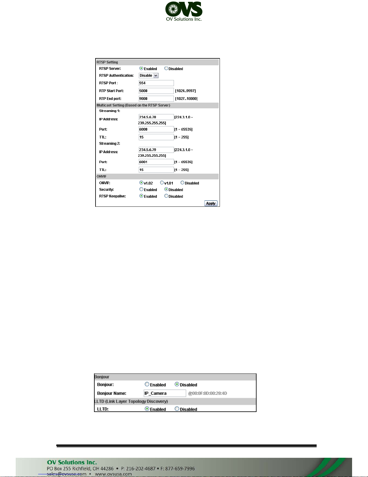
e. RTSP setting
(i)
(ii)
RTSP Server: enable or disable
RTSP Port: setup port for RTSP transmitting (Default: 554)
(iii) RTSP Start and End Port: in RTSP mode, you may use TCP and UDP
for connecting. TCP connection uses RTSP Port (554). UDP connection
uses RTSP Start and End Port.
f. Multicast Setting (Based on the RTSP Server)
Multicast is a bandwidth conservation technology. This function allow several
user to share the same packet sent from IP camera. To use Multicast,
appoint IP Address and port here. TTL means the life time of packet, The
larger the value is, the more user can receive the packet.
To use Multicast, be sure to enable the function "Receive Multicast" in
your media player.
g. ONVIF
Choose your ONVIF version and settings.
h. Bonjour
This function enable MAC systems to link to this IP camera. Key in the
name here.
User Manual
Page 23
i. LLTD
If your PC supports LLTD, enable this function then you can check the
connection status, properties, and device position(like IP address) of this IP
Camera in the network map.
2. Advanced
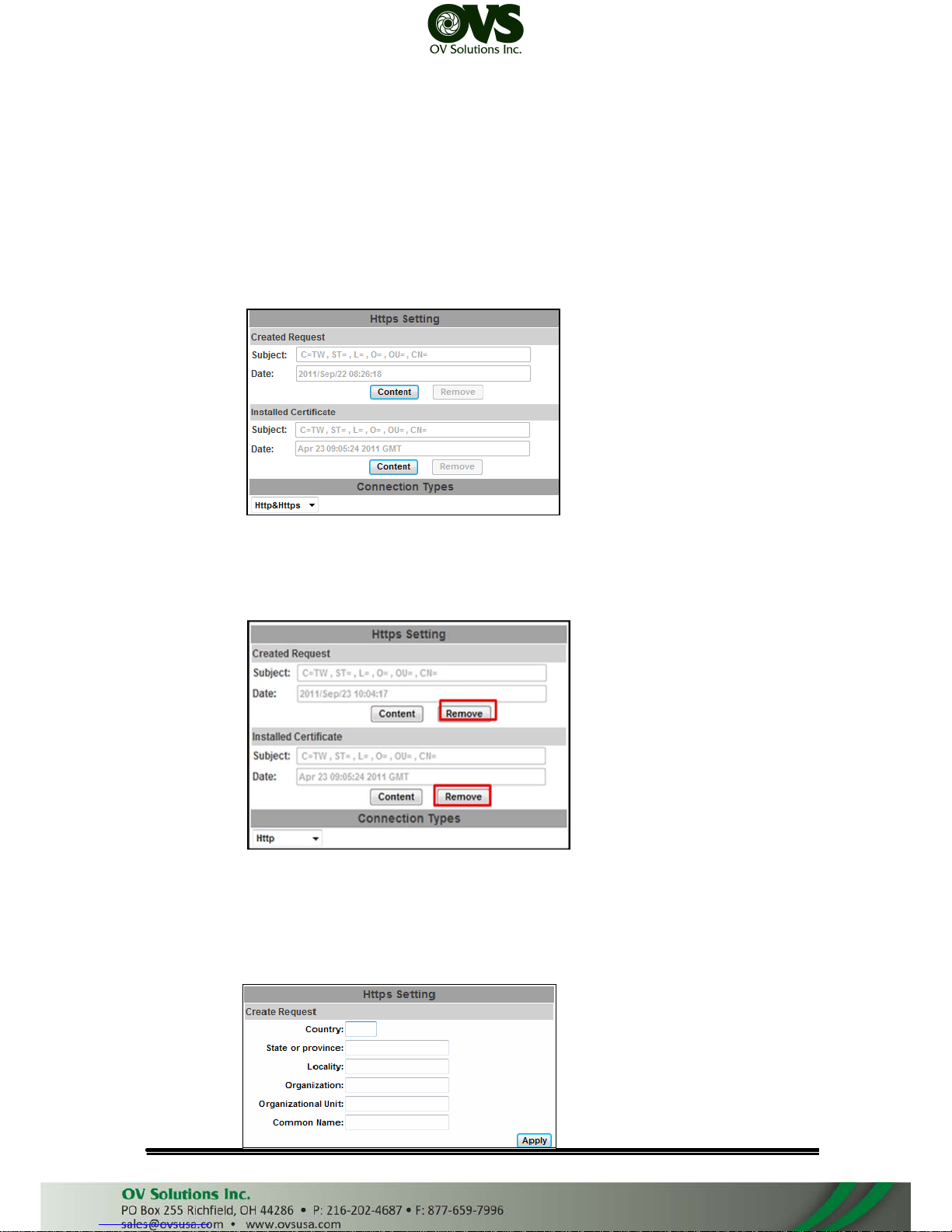
a. Https (Hypertext Transfer Protocol Secure): Https can help protect
streaming data transmission over the internal on the higher security level.
Https setting: Before setting new request, please remove old secure
identification at Http connection type.
(i)
(ii)
Created Request: remove secure identification in Created request
mode. There is a warning message showing. Please set “Yes” to
remove secure identification.
Setting the secure identification and apply it.
User Manual
Page 24
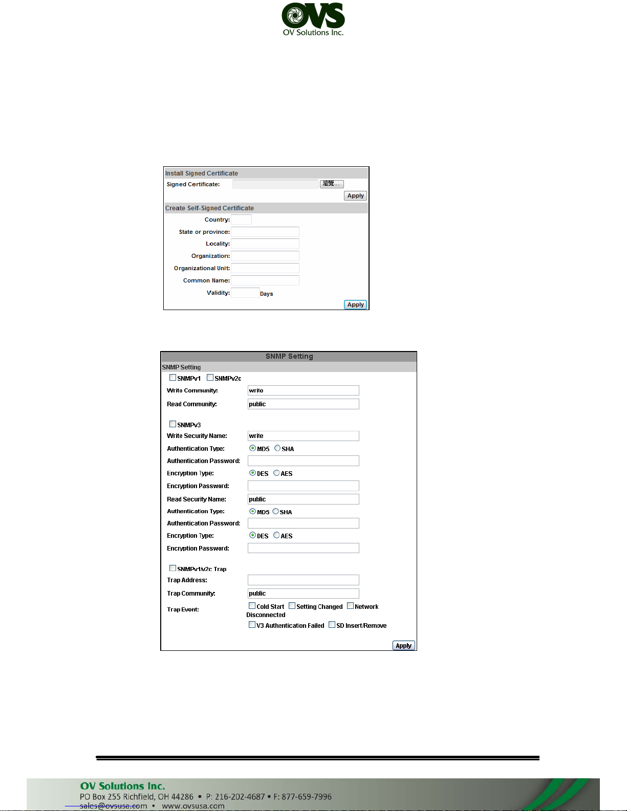
(iii) Installed Certificate: remove Certificate in .Installed Certificate mode.
There will be a warning message to check again.
(iv) There are two ways to set Certificate- Install Signed Certificate and
Create Self-Signed Certificate.
b. SNMP(Simple Network Management Protocol)
(i)
(ii)
Enable SNMPv1 or SNMPv2 and write the name of Write Community
and Read Community.
Enable SNMPv3, please set Security Name, Authentication Type,
Authentication Password, Encryption Type, Encryption Password of
Write mode and Read mode.
(iii) Enable SNMPv1/SNMPv2 Trap can detect the Trap server.
User Manual
Page 25
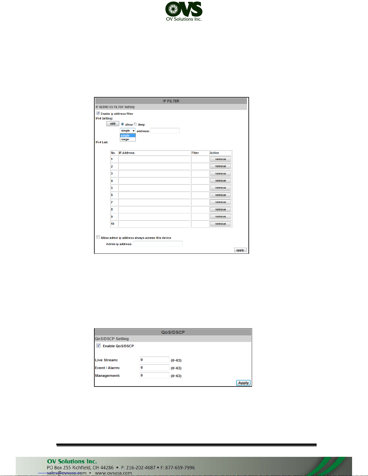
Please set what event need to detect.
c. Access List: ”Enable IP address filter” can set IP address which can allow
or deny to this camera. There are two options, single and range, for user to
set the IP address.
d. QoS/DSCP(Quality of Server/Differentiated Services Code-point):
DSCP specifies a simple mechanism for classifying and managing network
traffic and provide QoS on IP networks. DSCP is a 6-bit in the IP header for
packet classification purpose. Please define the reserve for Live Stream,
Event / Alarm and Management.
e. IEEE 802.1x: IEEE 802.1x is an IEEE standard for port-based Network
Access Control. It provides an authentication mechanism to device wishing
to attach to a LAN or WLAN.
The EAPOL protocol support service identification and optional point to
User Manual
Page 26
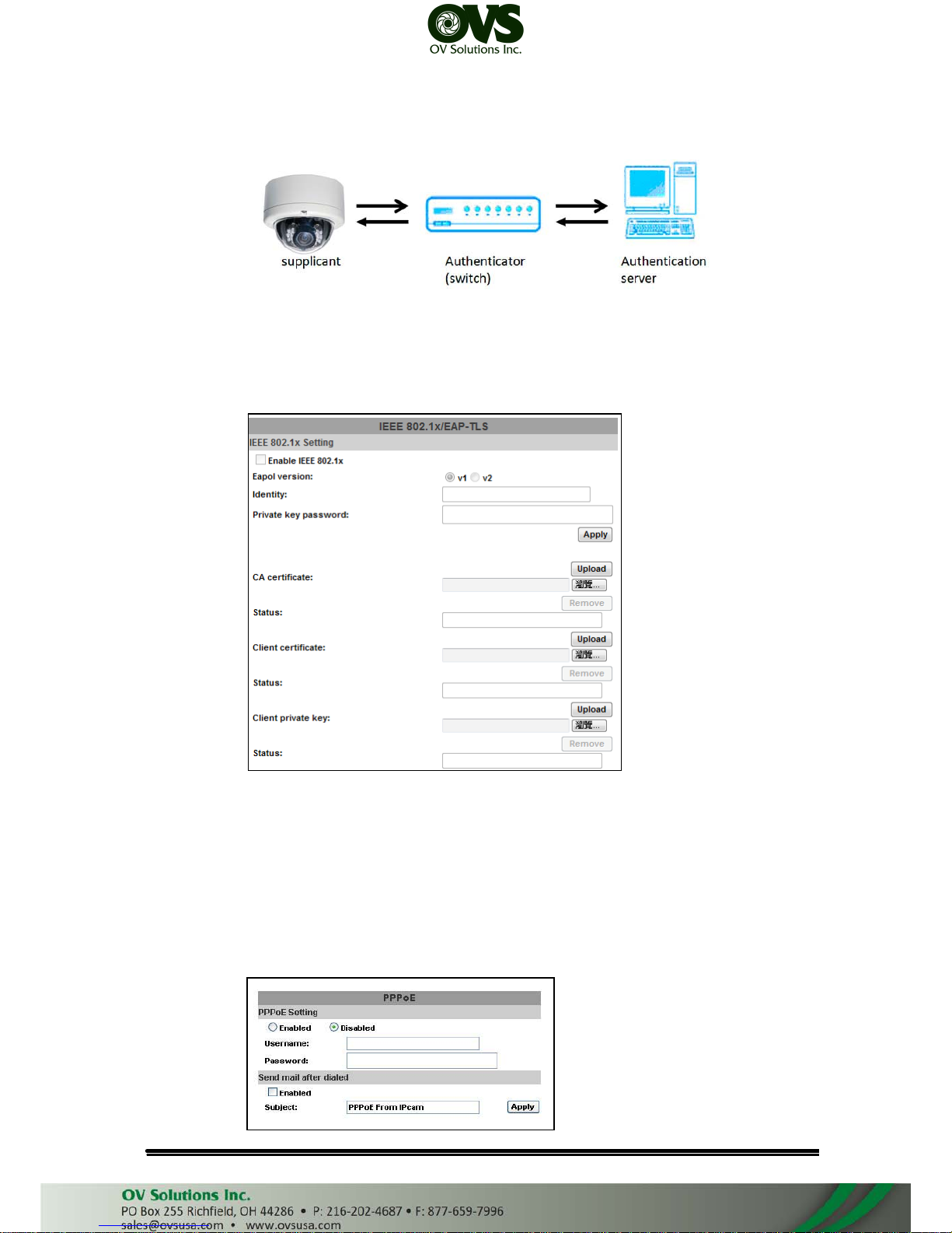
point encryption over the local LAN segment.
Please check what version of the authenticator and authentication
server support. This camera supports EAP-TLS method. Please enter ID,
password issued by the CA, then upload related certificates.
3. PPPoE & DDNS
a. PPPoE: Select “Enabled” to use PPPoE. Key-in Username and password
for the ADSL connection. Send mail after dialed: When connect to the
internet, it will send a mail to a specific mail account. For the mail setting,
please refer to “Mail and FTP” settings.
User Manual
Page 27
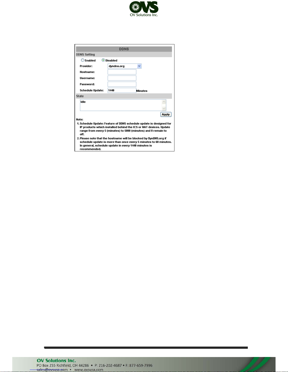
b. DDNS:
It supports DDNS (Dynamic DNS) service.
(i)
(ii)
Enable this service
Key-in the DynDNS server name, user name, and password.
(iii) Set up the IP Schedule update refreshing rate.
(iv) Click “Apply”
(v) If setting up IP schedule update too frequently, the IP may be blocked.
In general, schedule update every day (1440 minutes) is recommended
(vi) DDNS Status
• Updating: Information update
• Idle: Stop service
• DDNS registration successful, can now log by http://<username>.
ddns.camddns.com: Register successfully.
• Update Failed, the name is already registered: The user name has
already been used. Please change it.
• Update Failed, please check your internet connection: Network
connection failed.
• Update Failed, please check the account information you provide:
The server, user name, and password may be wrong.
4. Server setting
There are three choices of server types available: Email, FTP and
SAMBA. Select the item to display the detailed configuration options. You can
configure either one or all of them.
a. Mail Setting: To send out the video via mail of ftp, please set up the
configuration first.
User Manual
Page 28
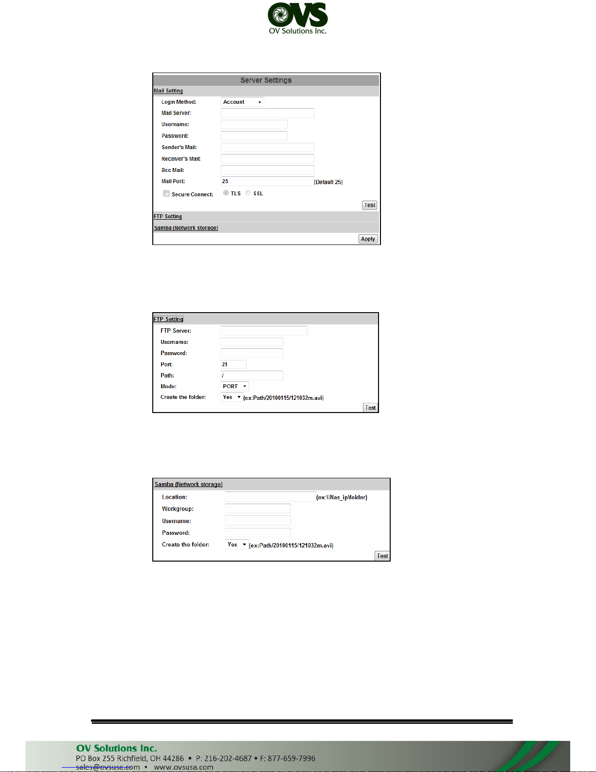
b. FTP: To send out the video via mail of ftp, please set up the configuration
first.
c. Samba: Select this option to send the media files via a network
neighborhood when an event is triggered
User Manual
Page 29
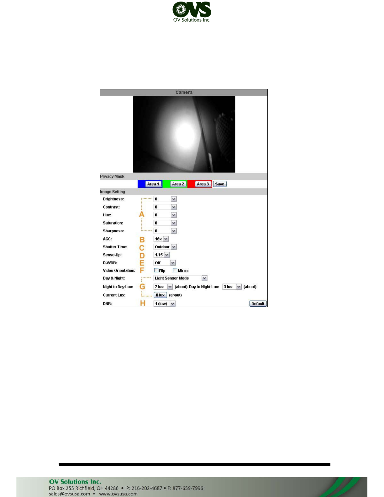
C. A/V Setting
1. Image Setting
For the security purpose, there are three areas can be setup for privacy
mask. Click Area button first and pull an area on the above image. Finally,
click Save button to reserve the setting.
Please refer to the details below for Image setting:
a. Brightness, Contrast, Hue, Saturation, Sharpness can be adjusted here.
b. AGC: The sensitivity of camera can adjusts with the environmental light in
order to avoid the images too light or too dark.
c. Shutter Time: You can use "Outdoor" or "Indoor" option, or fix it from 1/30 to
1/1000.
d. Sense-Up: incerase the sensitivity of camera to get brighter image at night.
e. WDR : Enable the function to reduce the contrast of background with
foreground(ex. people).
f. Video Orientation: Flip, mirror, or rotate the image as your requirement.
g. Day & Night: The camera can detect the light level of environment. If you
User Manual
Page 30
choose "Light Sensor Mode", the image will be turned to black and white at
night in order to keep clear. To set light sensor mode, appoint a lux stantard
of switching D/N here. Current lux value is provided for reference. Under
"Times Mode" according to given time. You can also control it by choosing
"Color" or "B/W" .
h. DNR: Adjust this option to reduce the noise.
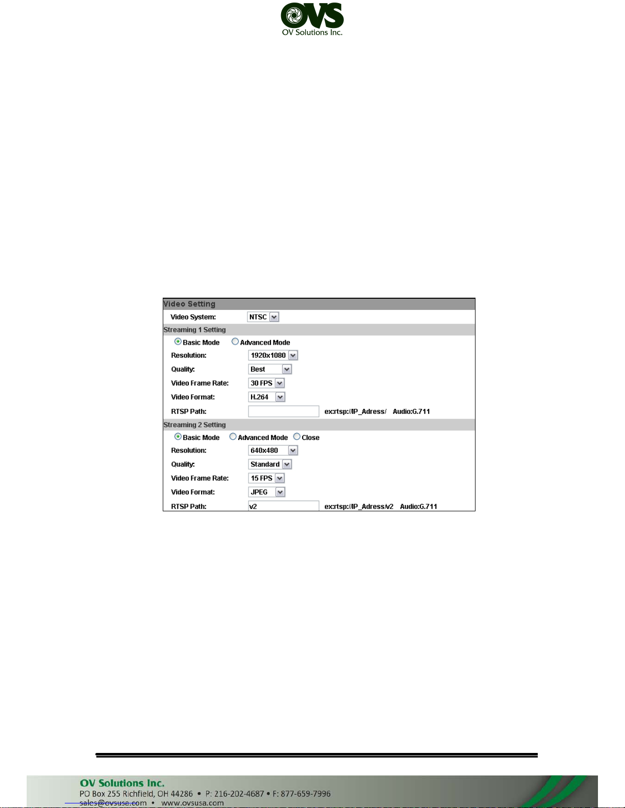
2. Video Setting
User may select 2 streaming output simultaneously:
Streaming 1 Setting: Basic mode and Advanced mode
Streaming 2 Setting: Basic mode, Advanced mode, and 3GPP mode
a. Basic Mode of Streaming 1 and Streaming 2:
(i)
(ii)
Resolution:
There are 5 resolutions can be chosen:
1920x1080, 1280x720, ,640x480, 320x240, 176x144
Quality:
There are 5 levels to choose:
Best/ High/ Standard/ Medium/ Low
The higher the quality is, the bigger the file size is. It might affect
Internet transmitting speed if the file gets too large.
(iii) Video Frame Rate: The video refreshing rate per second. In Streaming
1 you can choose up to 30 FPS, while in Streaming 2 only up to 15
FPS.
(iv) Video Format: H.264, MPEG4, or M-JPEG
(v) RTSP Path: Set the RTSP output connecting route
User Manual
Page 31
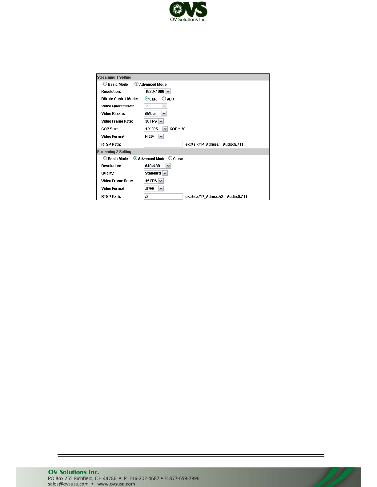
b. Advanced Mode of Streaming 1 and Streaming 2:
(i)
(ii)
Resolution
There are 5 resolutions can be chosen:
1920x1080, 1280x720, ,640x480, 320x240, 176x144
Bitrate Control Mode
There are CBR(Constant Bit Rate) and VBR(Variable Bit Rate) to be
choosed.
(iii) Video Quantitative
The quality adjustment of VBR. You can choose 1~10 compression rate
(iv) Video Bitrate
The quality adjustment of CBR. You can choose 32kbps~8Mkbps. The
higher the value is, the higher the image quality is.
(v) Video Frame Rate
The video refreshing rate per second. In Streaming 1 you can choose
up to 30 FPS, while in Streaming 2 only up to 15 FPS.
(vi) GOP Size
It means “Group of Pictures”. The higher the GOP is, the better the
quality is.
(vii)Video Format: H.264,MPEG4, or M-JPEG
(viii)RTSP Path: RTSP output connecting route
In Streaming 2, the option under Advanced Mode has no difference
with under Basic Mode.
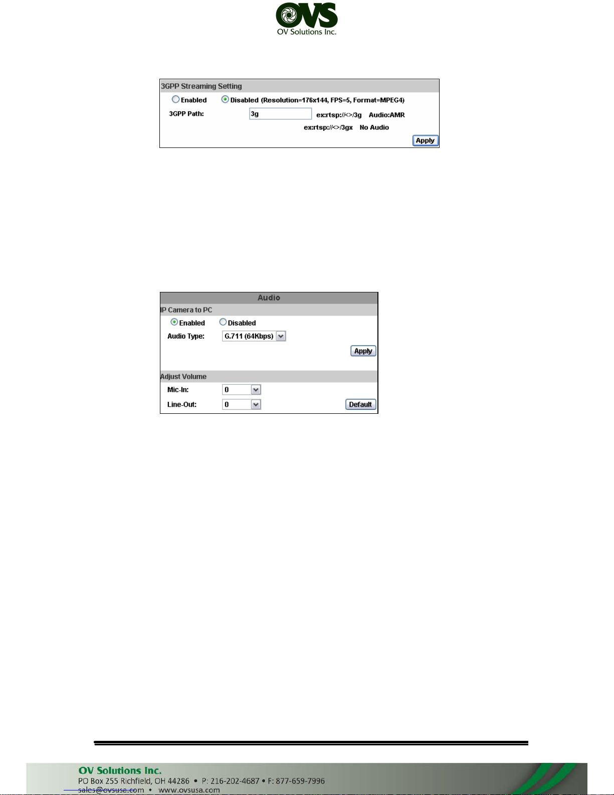
c. 3GPP Streaming mode:
User Manual
Page 32
(i)
(ii)
3GPP mode fixed setting: 176x144 resolution, 5FPS, MPEG4 format
Enable or Disable 3GPP Streaming
3GPP Path: 3GPP output connecting route
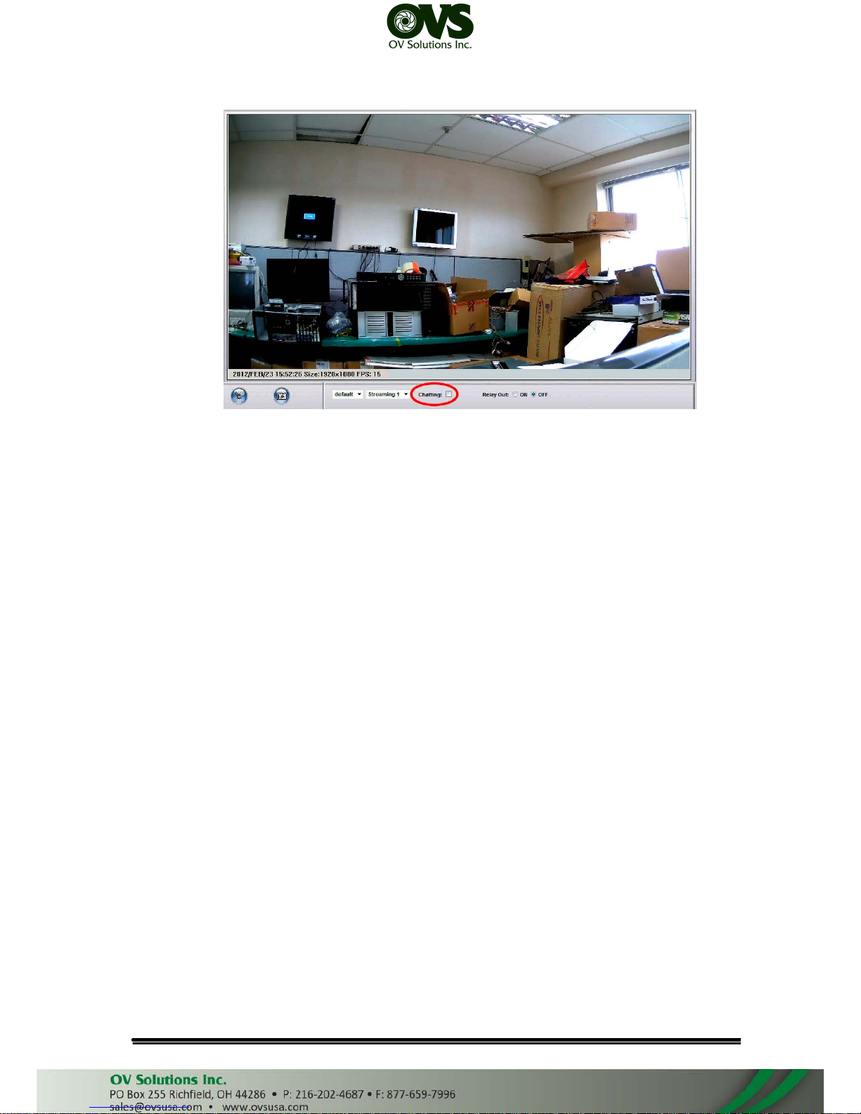
3. Audio:
IP Camera supports 2-way audio. User can send audio from IP Camera
mic input to remote PC; User can also send audio from remote PC mic to IP
Camera’s external speaker.
a. Audio from IP camera built-in mic to local PC: select “Enable” to start this
function.
b. Adjust Volume of audio.
c. Check “chatting” in the browsing page, then your voice can be propagated
from PC to camera.
User Manual
Page 33
The Audio will not be smooth when enable SD card
recording function simultaneously.
User Manual
Page 34
D. Event List
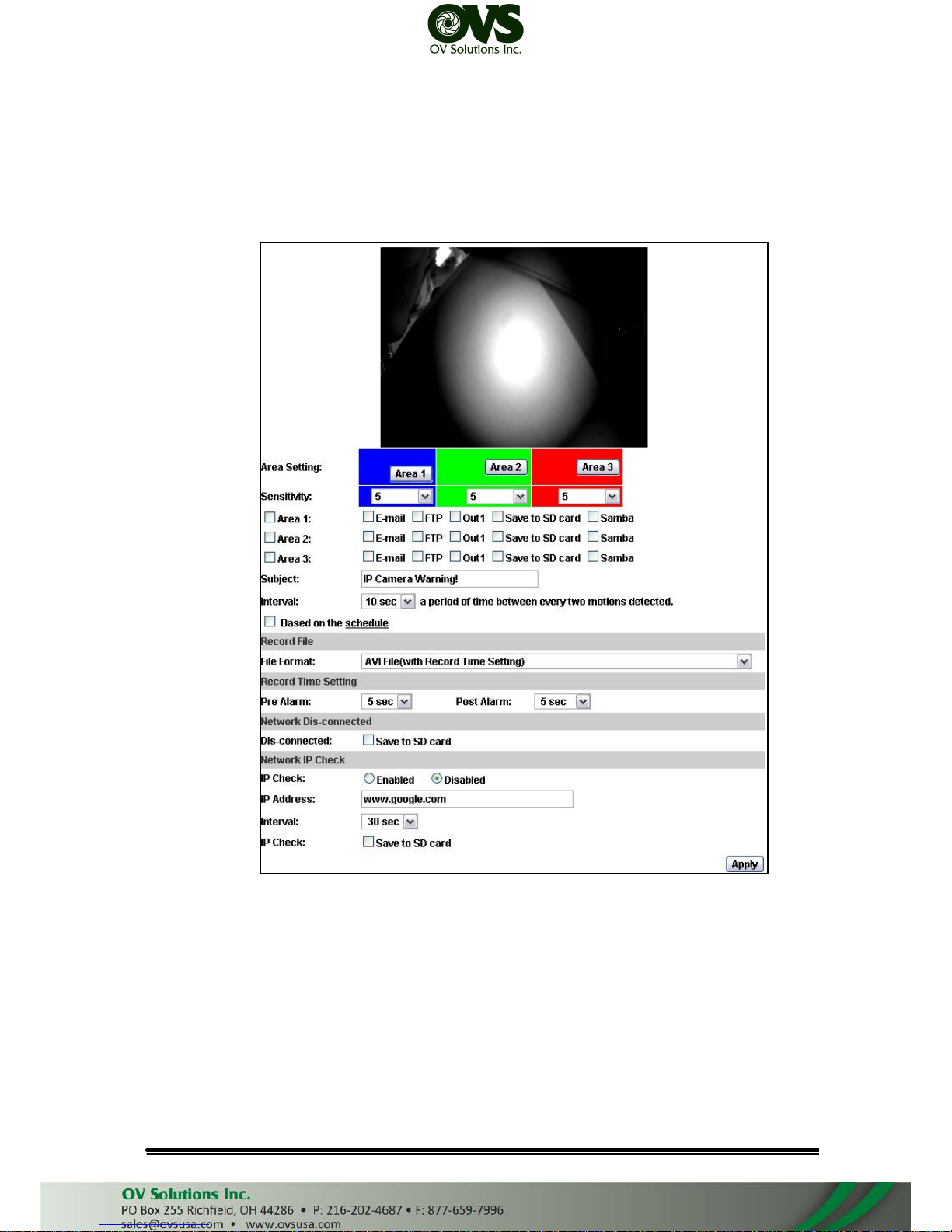
IP Camera provides multiple event settings.
1. Event Setting
a. Motion Detection
IP CAMERA allows 3 areas motion detection. When motion is triggered,
it can send video to some specific mail addresses, transmit the video to
remote ftp server, and save video to local SD card. To set up the motion
area, click “Area Setting”. Using mouse to drag and draw the area. The
same operation for area 2 and 3.
b. Rocord File: Choose AVI or JEPG file
c. Record Time Setting
Pre Alarm and Post Alarm setups for video start and end time when motion
User Manual
Page 35
detected, I/O, or other devices got triggered
d. Network Dis-connected
When the network is down, it will save the video to local SD card.
This function is only enabled under wire connection.
e. Network IP check:
Whenever the connection is down, it records the video to SD card. Make
sure the video recording is continuous. To use this function, key in the
IP address of the PC which has recording software installed. Enable the
function of “Save to SD card”, then click “Apply”.
The interval of two video files recorded on SD card is fixed with 30
seconds.
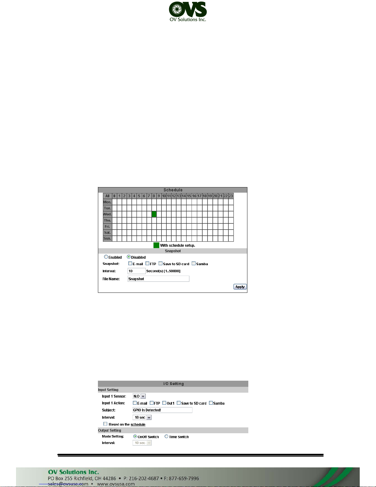
2. Schedule
a. Schedule: After complete the schedule setup, the camera data will be
recorded according to the schedule setup.
b. Snapshot: After enable the snapshot function, user can select the storage
position of snapshot file, the interval time of snapshot and the reserved file
name of snapshot.
c. Interval: The interval between two snapshots.
3. I/O Setting
User Manual
Page 36
a. Input Setting:
IP Camera supports input and output. When the input condition is triggered,
it can send the video to some specific mail addresses, transmit the video
to remote FTP server, trigger the relay, save video to local SD card or to
SAMBA.
b. Output Setting:
"OnOff Switch" means the camera executes the action when triggered.
"Time Switch" means the camera executes the action according to the
interval you choose after triggered.
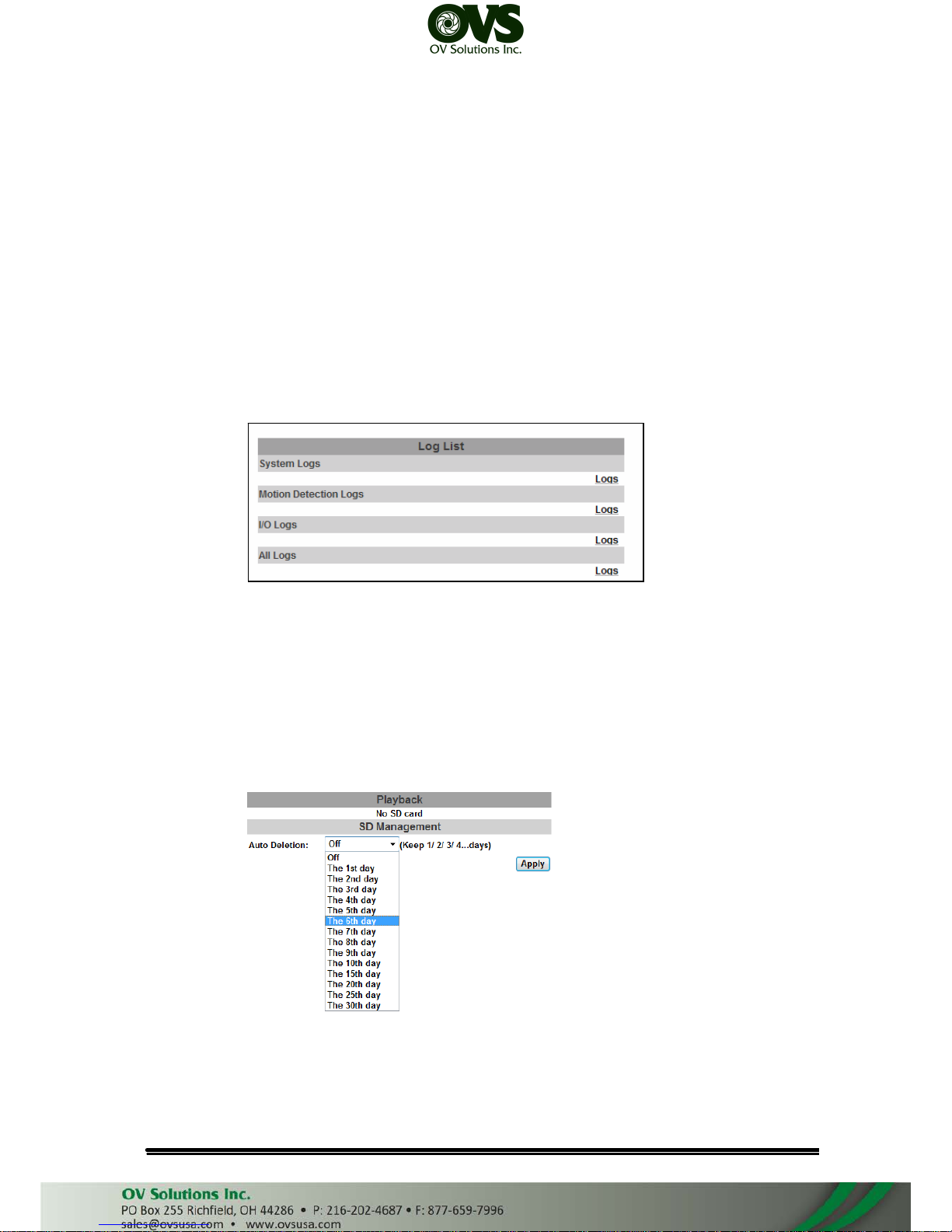
4. Log List
Sort by System Logs, Motion Detection Logs and I/O Logs. In addition,
System Logs and I/O Logs won’t lose data due to power failure
5. MicroSD card
Choose “The 1st day” meads the recoding file will be keep one day.
Example: It is five o’clock now. Choose “The 1st day”. The files will be kept
from five o’clock yesterday to five o’clock today.
Note:The use of the SD card will affect the operation of the IP Camera
slightly, such as affecting the frame rate of the video.
User Manual
Page 37
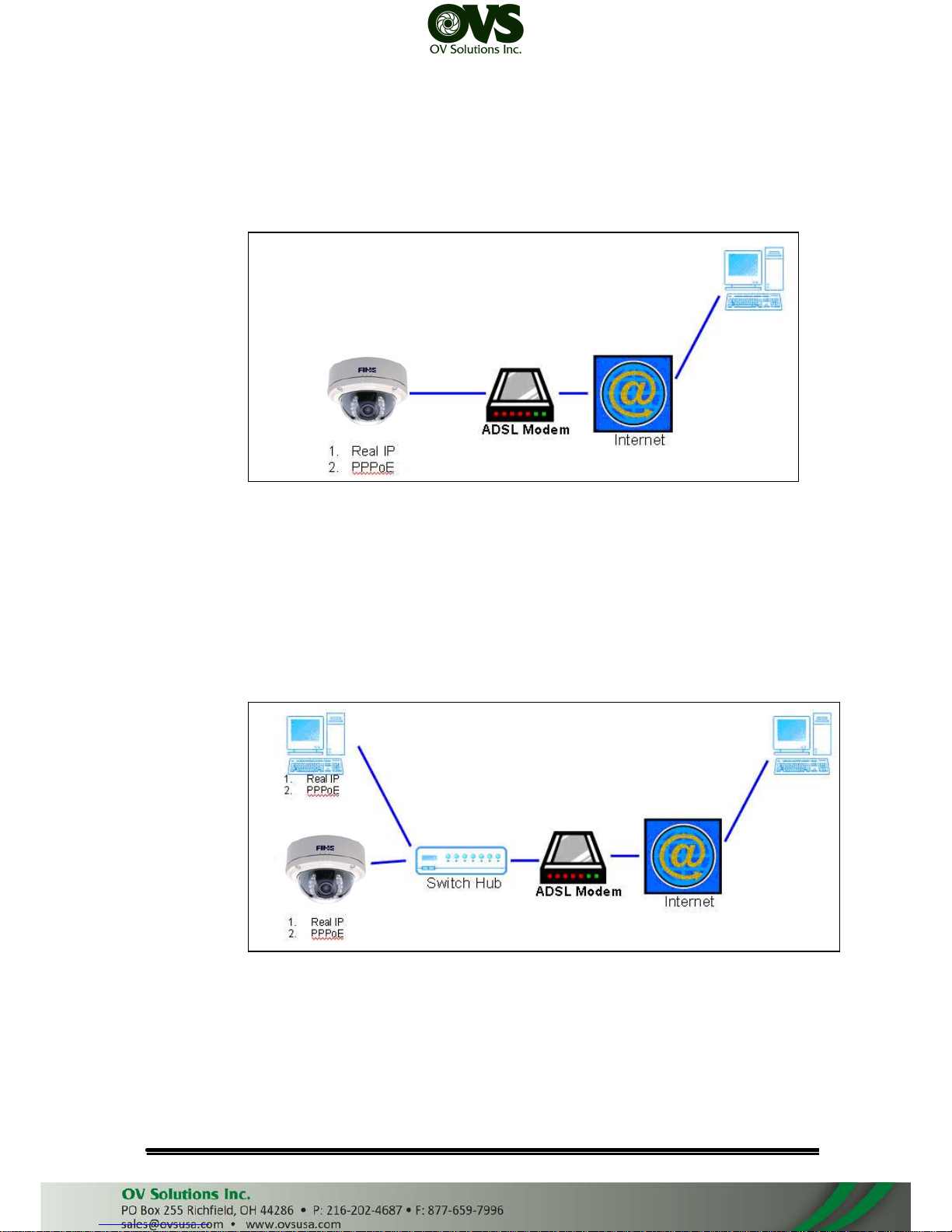
V. Network Configuration
• Configuration 1:
a. Internet Access: ADSL or Cable Modem
b. IP address: One real IP or one dynamic IP
c. Only IP Camera connects to the internet
d. For fixed real IP, set up the IP into IP Camera. For dynamic IP, start PPPoE.
• Configuration 2:
a. Internet AccessL: ADSL or Cable Modem
b. IP address: More than one real IP or one dynamic IP
c. IP Camera and PC connect to the internet
d. Device needed: Switch Hub
e. For fixed real IP, set up the IP into IP Camera and PC. For dynamic IP, start
PPPoE.
User Manual
Page 38
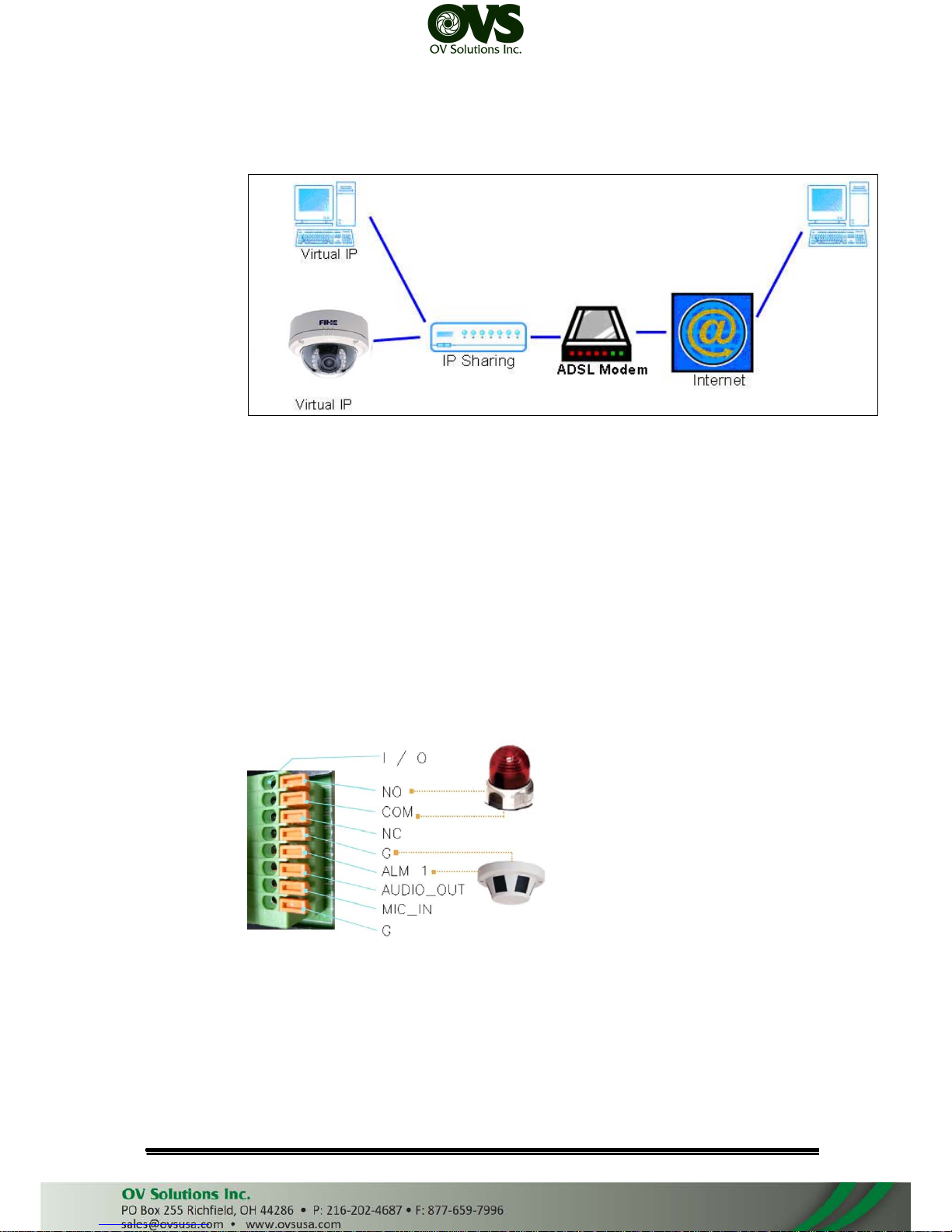
• Configuration 3:
a. Internet Access: ADSL or Cable Modem
b. IP address: one real IP or one dynamic IP
c. IP Camera and PC connect to the internet
d. Device needed: IP sharing
e. Use virtual IP, set up port forwarding in IP sharing.
VI. I/O Configuration
• I/O Connection
Use the terminal block in the camera as below:
a. Please connect the COM & N.O / N.C pin (depend on the device) to the
external relay (buzzer) device.
User Manual
Page 39
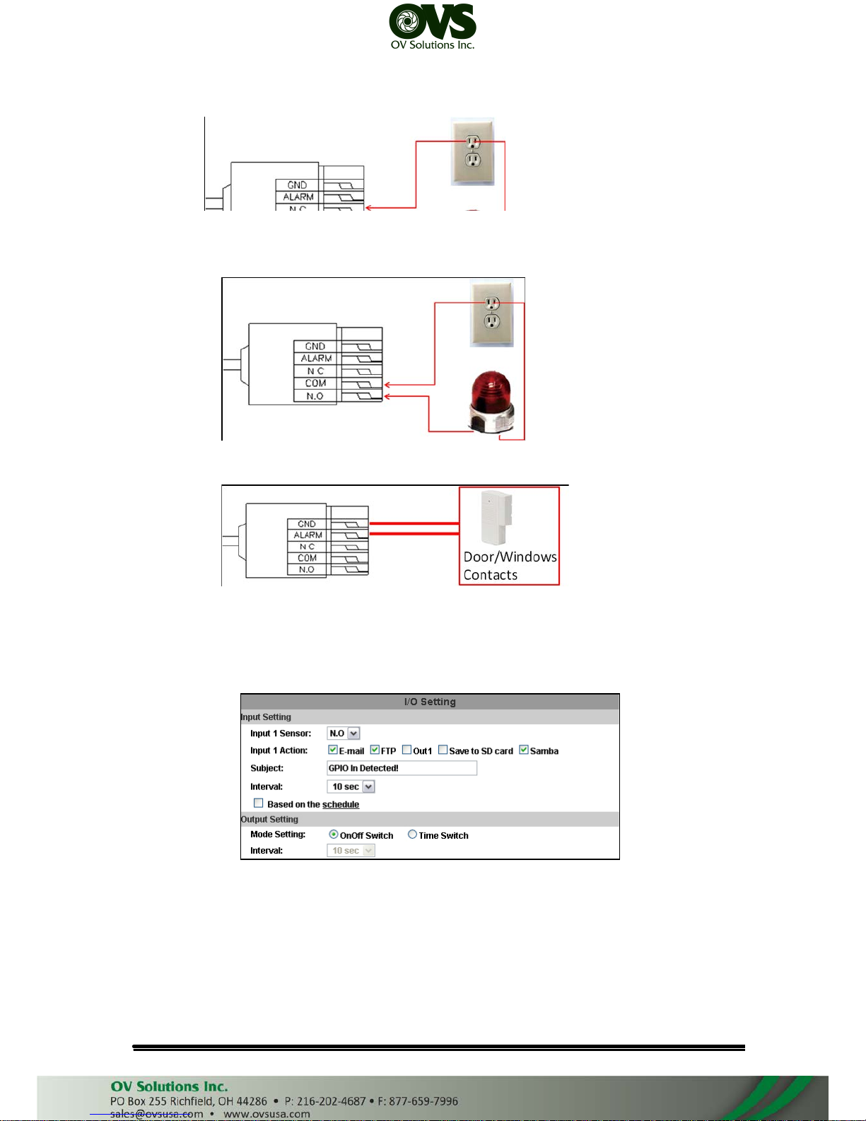
Or
b. Please connect the GND &Alarm pin to the external Trigger Device.
• I/O Setup
a. Click I/O Setting from the system setup page via IE, and check “Out1” to
enable I/O signal.
b. Click ON/OFF from the setup main page via IE to control relay out signal.
User Manual
Page 40
VII.
Factory Default
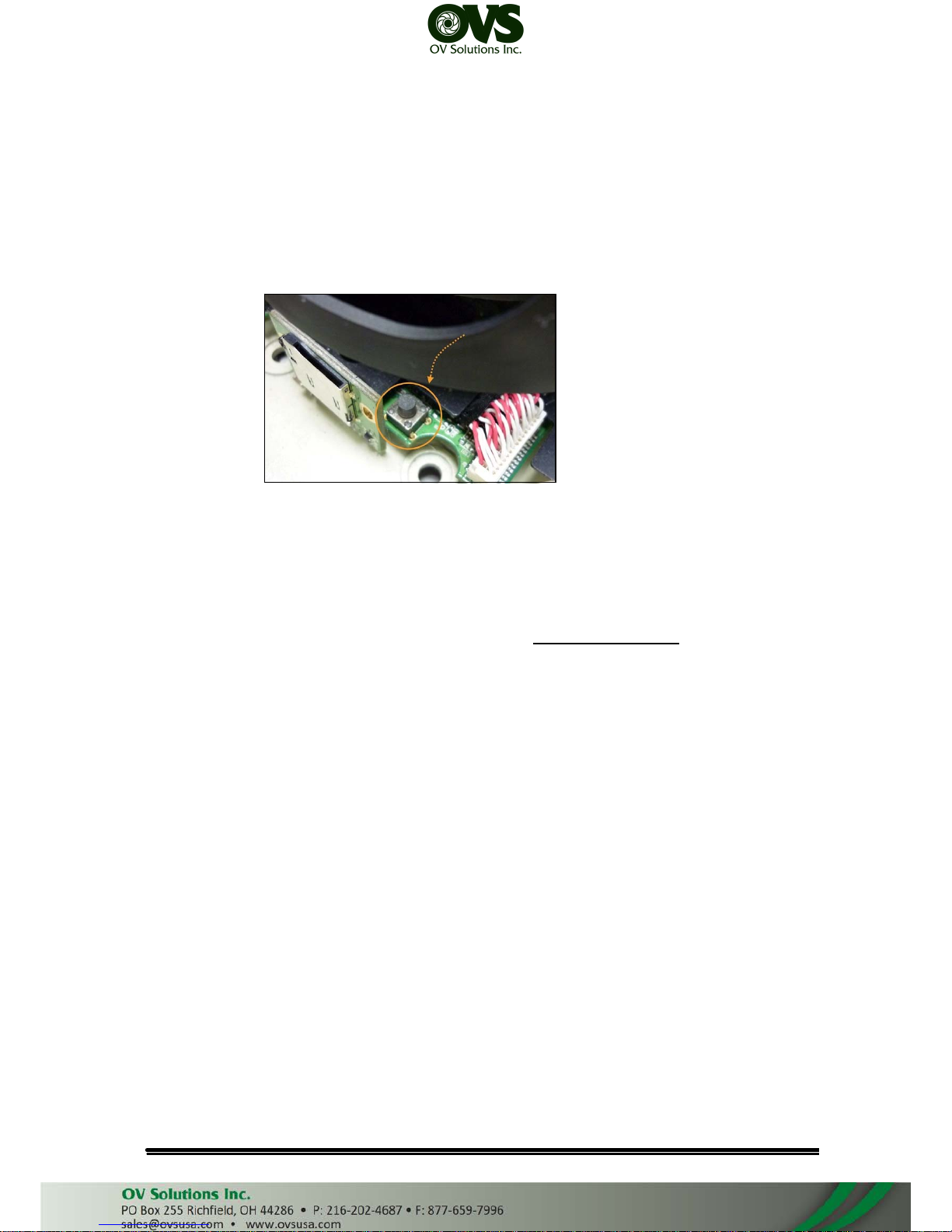
• To recover the default IP address and password, please follow the following
steps.
• Remove the power, Internet, and the dome cover. Press and hold the button as
the picture below.
• Connect power to the camera, and do not release the button during the system
booting.
• It will take around 30 seconds to boot the camera.
• Release the button when camera finishes proceed.
• Re-login the camera using the default IP (http://192.168.1.20), and user name
(admin), password (admin).
VIII.
Package contents
• IP Camera Network Camera
• Adaptor
• CD (Including User manual and IP installation tool)
User Manual
Page 41

IX. Appendix
The following is the Micro SD Card recommended:
Transcend SDHC class4
16GB
SDHC class4 32GB
SD class4 16GB
SD class4 32GB
SDHC class6 4GB
SDHC class6 8GB
SDHC class6 16GB
SD class6 4GB
SD class6 8GB
SD class6 16GB
SDHC class10 4GB
SDHC class10 8GB
SDHC class10 16GB
SanDisk
SDHC class4 4GB
SDHC class4 8GB
SDHC class4 16GB
SDHC class4 32GB
User Manual
 Loading...