

Page 1
105
65 Series - Power relays 20 - 30 A
1NO+1NC (SPST-NO+SPST-NC) 1NO+1NC (SPST-NO+SPST-NC)
20/40* 20/40*
250/400 250/400
5,000 5,000
1,000 1,000
1.1 1.1
20/0.8/0.5 20/0.8/0.5
1,000 (10/10) 1,000 (10/10)
AgCdO AgCdO
6 - 12 - 24 - 48 - 60 - 110 - 120 - 230 - 240 - 400
6 - 12 - 24 - 48 - 60 - 110 - 125 - 220
2.2/1.3 2.2/1.3
(0.8…1.1)U
N
(0.8…1.1)U
N
(0.85…1.1)U
N
(0.85…1.1)U
N
0.8 UN/0.6 U
N
0.8 UN/0.6 U
N
0.2 UN/0.1 U
N
0.2 UN/0.1 U
N
10 · 106/30 · 10
6
10 · 106/30 · 10
6
80 · 10
3
80 · 10
3
10/12 10/12
44
1,500 1,500
–40…+75 –40…+75
RT I RT I
Contact specification
Contact configuration
Rated current/Maximum peak current A
Rated voltage/Maximum switching voltage V AC
Rated load AC1 VA
Rated load AC15 (230 V AC) VA
Single phase motor rating (230 V AC) kW
Breaking capacity DC1: 30/110/220 V A
Minimum switching load mW (V/mA)
Standard contact material
Coil specification
Nominal voltage (U
N
) V AC (50/60 Hz)
V DC
Rated power AC/DC VA (50 Hz)/W
Operating range AC
DC
Holding voltage AC/DC
Must drop-out voltage AC/DC
Technical data
Mechanical life AC/DC cycles
Electrical life at rated load AC1 cycles
Operate/release time ms
Insulation between coil and contacts (1.2/50 µs)
kV
Dielectric strength between open contacts V AC
Ambient temperature range °C
Environmental protection
Approvals (according to type)
* With the AgSnO
2
material the
maximum
peak
current is 120 A - 5 ms on NO contact.
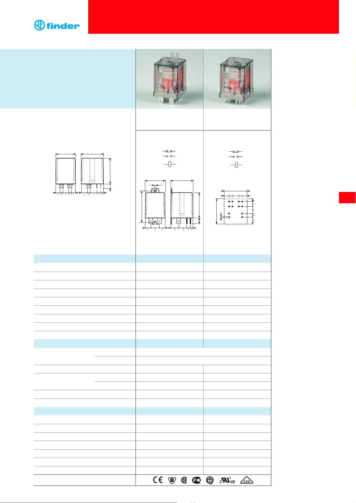
Copper side view
65.31 65.61
• 20 A rated contacts
• Flange mount/Faston 250
(6.3x0.8 mm) connection
Features
20 A Power relays
1 NO + 1 NC (SPST-NO + SPST-NC)
65.31 Flange mount
(Faston 250 connections)
65.61 PCB mount
•
AC coils & DC coils
• Cadmium Free option available
• 20 A rated contacts
• PCB mount -
bifurcated terminals
32.2 36.5
10.3
4.6
10.7
6.3
6.8 9.6 4.64.6 6.8
7. 5
42.2
4.6
65.61
65
A1 A2
12.6
9.1
2221
36.5
52.2
11 14
32.2
3.6
42.2
36.5
9.6
4.6136.39.1 14
A1 A2
32.2
211422
11
A1
2221
A2
11 14
6.8 4.6 9.4 4.6 6.8
2
4.6
6.3
4.6
10.3
Page 2
1 NO, ≥ 3 mm* 1 NO, ≥ 3 mm*
30/50** 30/50**
250/400 250/400
7,500 7,500
1,250 1,250
1.5 1.5
30/1.1/0.7 30/1.1/0.7
1,000 (10/10) 1,000 (10/10)
AgCdO AgCdO
6 - 12 - 24 - 48 - 60 - 110 - 120 - 230 - 240 - 400
6 - 12 - 24 - 48 - 60 - 110 -125 - 220
2.2/1.3 2.2/1.3
(0.8…1.1)U
N
(0.8…1.1)U
N
(0.85…1.1)U
N
(0.85…1.1)U
N
0.8 UN/0.6 U
N
0.8 UN/0.6 U
N
0.2 UN/0.1 U
N
0.2 UN/0.1 U
N
10 · 106/30 · 10
6
10 · 106/30 · 10
6
50 · 10
3
50 · 10
3
15/4 15/4
44
2,500 2,500
–40…+75 –40…+75
RT I RT I
* Distance between contacts ≥ 3 mm
(EN 60335-1).
** With the AgSnO2 material the maximum
peak current is 120 A - 5 ms on NO
contact.
Contact specification
Contact configuration
Rated current/Maximum peak current A
Rated voltage/Maximum switching voltage V AC
Rated load AC1 VA
Rated load AC15 (230 V AC) VA
Single phase motor rating (230 V AC) kW
Breaking capacity DC1: 30/110/220 V A
Minimum switching load mW (V/mA)
Standard contact material
Coil specification
Nominal voltage (U
N
) V AC (50/60 Hz)
V DC
Rated power AC/DC VA (50 Hz)/W
Operating range AC
DC
Holding voltage AC/DC
Must drop-out voltage AC/DC
Technical data
Mechanical life AC/DC cycles
Electrical life at rated load AC1 cycles
Operate/release time ms
Insulation between coil and contacts (1.2/50 µs)
kV
Dielectric strength between open contacts V AC
Ambient temperature range °C
Environmental protection
Approvals (according to type)
106
65 Series - Power relays 20 - 30 A
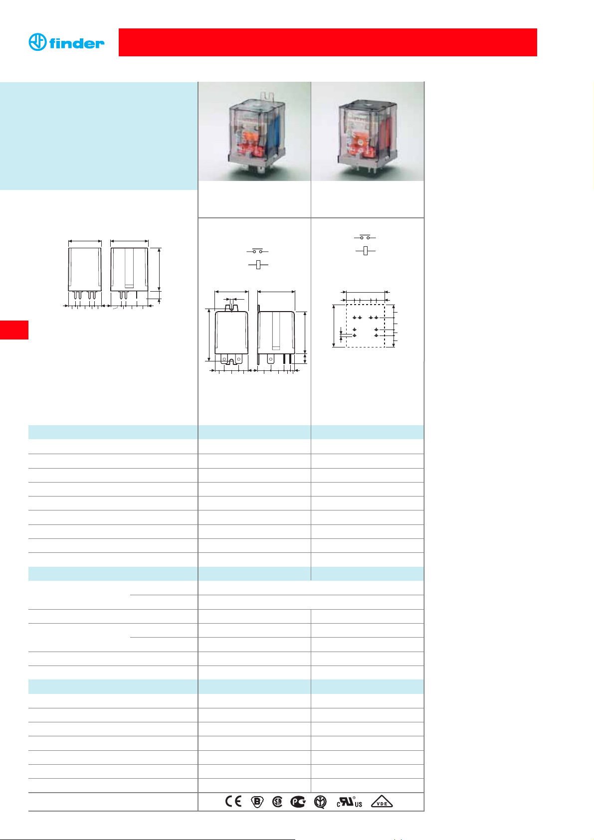
65.31-0300 65.61-0300
Copper side view
Features
30 A Power relays
1 NO (SPST-NO)
65.31-0300 Flange mount
(Faston 250 connections)
65.61-0300 PCB mount
• ≥
3 mm contact gap
•
AC coils & DC coils
• Cadmium Free option available
• 30 A rated contacts
• Flange mount/Faston 250
(6.3x0.8 mm) connection
• 30 A rated contacts
• PCB mount -
bifurcated terminals
32.2 36.5
10.3 10.7
6.8 9.6 4.64.6 6.8
7. 5
42.2
4.6
10.9
65.61-0300
65
11 14
A1 A2
52.2
32.2
3.6
9.1
36.5
12.6
42.2
9.6
4.6136.39.1 14
11 14
A1 A2
32.2
6.8 4.6 9.4 4.6 6.8
11 14
36.5
2
A2
A1
10.9
10.7
4.6
10.3
Page 3

107
Example: 65 series power relay, PCB with bifurcated terminals, 1 NC + 1 NO (SPST-NO + SPST-NC) contact, 12 V DC coil.
Ordering information
A: Contact material
0 = Standard AgCdO
4 = AgSnO
2
B: Contact circuit
0 = 1 NO + 1 NC
(SPST-NO + SPST-NC)
3 = NO (≥ 3 mm contact gap)
Series
Type
3 = Faston 250 (6.3x0.8 mm)
with rear flange mount
6 = PCB with bifurcated terminals
No. of poles
1 = 1 NC + 1 NO (SPST-NO + SPST-NC)
Coil version
8 = AC (50/60 Hz)
9 = DC
Coil voltage
see coil specifications
6 1 0 09
D: Special versions
0 = Standard
5 = Top flange mount
7 = Top 35 mm rail (EN 50022) mount
8 = Rear 35 mm rail (EN 50022) mount
C: Options
0 = None
0 0
ABCD
... .
01265
Insulation
Insulation according to EN 61810-1 ed. 2 insulation rated voltage V 250 400
rated impulse withstand voltage kV 4 4
pollution degree 3 2
overvoltage category III III
Insulation between coil and contacts (1.2/50 µs) kV 4
Dielectric strength between open contacts V AC 1,500 (changeover); 2,500 (normally open)
Conducted disturbance immunity
Burst (5...50)ns, 5 kHz, on A1 - A2 EN 61000-4-4 level 4 (4 kV)
Surge (1.2/50 µs) on A1 - A2 (differential mode) EN 61000-4-5 level 4 (4 kV)
Other data
Bounce time: NO/NC ms
5/6 (1 normally open +1 normally closed)
7/– (normally open)
Vibration resistance (5…55)Hz, max. ± 1 mm: NO/NC g/g 10/4
Shock resistance g 15
Power lost to the environment
1 normally open+1 normally closed 1 normally open
without contact current W 1.3 1.3
with rated current W 2.1 3.1
Recommended distance between relays mounted on PCB mm ≥ 5
Technical data
65 Series - Power relays 20 - 30 A
Type
Coil version
AB C D
65.31 AC-DC 0 - 4 0 - 3 00- 5 - 7 - 8
65.61 AC-DC 0 - 4 0 - 3 00
Selecting features and options: only combinations in the same row are possible.
Preferred selections for best avaliability are shown in bold.
D: Special version 5
Top flange mount
D: Special version 8
Rear 35 mm rail mount
D: Special version 7
Top 35 mm rail mount
Descriptions: Options and Special versions
65
6
.
3
52.3
Page 4

Coil specifications
Contact specification
Nominal Coil Operating range Resistance Rated coil
voltage code
consumption
U
N
U
min
U
max
R
I at UN (50Hz)
VVVΩ mA
6 8.006 4.8 6.6 4.6 367
12 8.012 9.6 13.2 19 183
24 8.024 19.2 26.4 74 90
48 8.048 38.4 52.8 290 47
60 8.060 48 66 450 37
110 8.110 88 121 1,600 20
120 8.120 96 132 1,940 18.6
230 8.230 184 253 7,250 10.5
240 8.240 192 264 8,500 9.2
400 8.400 320 440 19,800 6
AC coil data
Nominal Coil Operating range Resistance Rated coil
voltage code
consumption
U
N
U
min
U
max
R I at U
N
VVVΩ mA
6 9.006 5.1 6.6 28 214
12 9.012 10.2 13.2 110 109
24 9.024 8.8 26.4 445 54
48 9.048 40.8 52.8 1,770 27.1
60 9.060 51 66 2,760 21.7
110 9.110 93.5 121 9,420 11.7
125 9.125 100 137.5 12,000 10.4
220 9.220 176 242 37,300 5.8
DC coil data
F 65 - Electrical life (AC) v contact current
1 - Max. permitted coil voltage.
2 - Min. pick-up voltage with coil at ambient temperature.
1 - Max. permitted coil voltage.
2 - Min. pick-up voltage with coil at ambient temperature.
108
65 Series - Power relays 20 - 30 A
(A)
0
2010 255
30
15
10
6
5·10
6
10
5
5·10
4
Cycles
• When switching a resistive load (DC1) having voltage and current
values under the curve, an electrical life of ≥ 80·103can be expected.
• In the case of DC13 loads, the connection of a diode in parallel with
the load will permit a similar electrical life as for a DC1 load.
Note: the release time for the load will be increased.
220
20
10
6
4
2
1
0.6
0.4
0.2
0.1
30
20 60
100 140 180
H 65 - Maximum DC1 breaking capacity
DC breaking current (A)
DC voltage (V)
1 normally open + 1 normally closed type
1 normally open type
R 65 - DC coil operating range v ambient temperature
(°C)
6030 50
2.0
10-20
1.0
0.5
1.5
0407020-10
U
U
N
80
2
1
R 65 - AC coil operating range v ambient temperature
(°C)
6030 50
2.0
10-20
1.0
0.5
1.5
0407020-10
U
U
N
80
2
1
Resistive load - cosϕ = 1
Inductive load - cosϕ = 0.4
limit for 1NO+1NC types
65
 Loading...