

Page 1
2 CO (DPDT) 3 CO (3PDT)
2 NO (DPST-NO), ≥3 mm*
3 NO (3PST-NO), ≥3 mm*
16/30** 16/30**
250/400 250/400
4,000 4,000
750 750
0.8/— 0.8/1.5 0.8/— 0.8/1.5
16/0.6/0.4 16/1.1/0.7
1,000 (10/10) 1,000 (10/10)
AgCdO AgCdO
6 - 12 - 24 - 48 - 60 - 110 - 120 - 230 - 240 - 400
6 - 12 - 24 - 48 - 60 - 110 - 125 - 220
2.2/1.3 3/3
(0.8…1.1)U
N
(0.85…1.1)U
N
(0.8…1.1)U
N
(0.85…1.1)U
N
0.8 UN/0.6 U
N
0.8 UN/0.6 U
N
0.2 UN/0.1 U
N
0.2 UN/0.1 U
N
10 · 106/30 · 10
6
10 · 106/30 · 10
6
100 · 10
3
100 · 10
3
10/10 20/4
66
1,500 2,500
–40…+70 –40…+50
RT I RT I
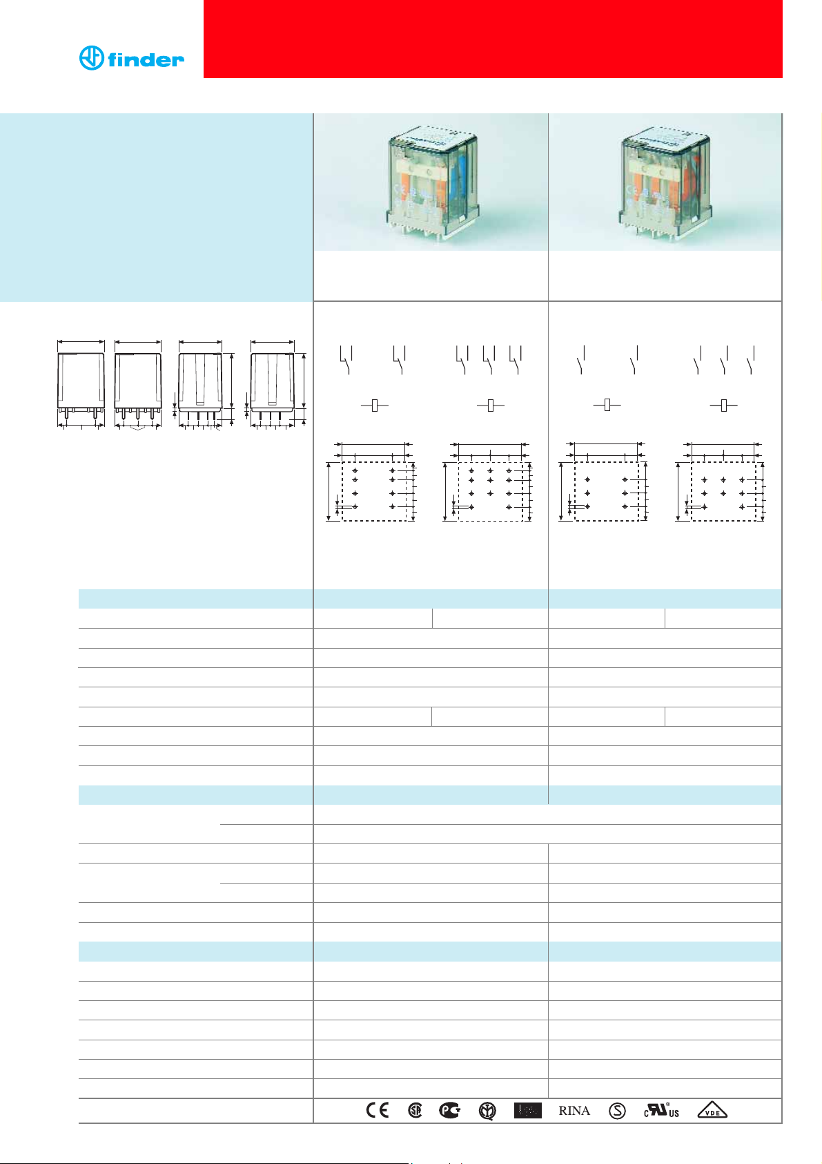
• 2 & 3 pole changeover contact
• PCB mount
• 2 & 3 pole normally open contact
(
≥ 3 mm contact gap)
• PCB mount
Contact specification
Contact configuration
Rated current/Maximum peak current A
Rated voltage/Maximum switching voltage V AC
Rated load AC1 VA
Rated load AC15 (230 V AC) VA
Motor rating (230/400 V AC) kW
Breaking capacity DC1: 30/110/220 V A
Minimum switching load mW (V/mA)
Standard contact material
Coil specification
Nominal voltage (U
N
) V AC (50/60 Hz)
V DC
Rated power AC/DC VA (50 Hz)/W
Operating range AC
DC
Holding voltage AC/DC
Must drop-out voltage AC/DC
Technical data
Mechanical life AC/DC cycles
Electrical life at rated load AC1 cycles
Operate/release time ms
Insulation between coil and contacts (1.2/50 µs)
kV
Dielectric strength between open contacts V AC
Ambient temperature range °C
Environmental protection
Approvals (according to type)
62.22 62.23 62.22 - 0300 62.23 - 0300
Copper side view Copper side view Copper side view Copper side view
* Distance between contacts ≥ 3 mm
(EN 60730-1).
** With the AgSnO
2
material the
maximum
peak
current is 120 A - 5 ms (NO contact).
FORUL H
ORSEPOWER ANDPILOTDUTY RATINGS
SEE“General technical information” page
V
62.22 / 62.23 62.22-0300 / 62.23-0300
1
Features
Printed circuit mount
16 A Power relay
• 2 & 3 Pole changeover contacts or NO
(≥ 3 mm contact gap)
• AC coils & DC coils
• Reinforced insulation between coil and
contacts according to EN 60335-1, with
6 mm clearance & 8 mm creepage distance
• SELV coil-contact separator option
• Cadmium Free contact material options
62.23
62.2x-0300
8
8
38.2
22.2
62.22
62 Series - Power relays 16 A
35.8
45.6
3.5
8
8.65
7.6 8.3
3.5
9.7
5.5 5.75
8
38.2
11.1
8.65
35.8
7.6 8.3
12 14 32 34
1
4
45.6
9.7
11.25
11 31
7
AB
A1 A2
38.2
22.28
13
12
32
4 6
14
34
79
11
35.8
2
31
AB
A2A1
36
9
8
12 14 22 24 32 34
A1 A2
5.6
5.8
8
35.8
7.6
8.8
4
1
25836
11 21 31
7
AB
38.2
11.1
11.18
13
2
12
22
4 6
5
14
24
79
8
11
21
2
AB
8
32
34
31
A2A1
14 34
4
11 31
9
5.6
5.8
8
7.6
8.8
7
AB
A1 A2
4 6
14
79
11
35.8
2
AB
9
38.2
8
22.28
34
31
A2A1
6
11.4
8
7.6
8.8
14 24 34
4
586
11 21 31
7
AB
A1 A2
38.2
11.1
11.18
4 6
5
1411242134
8
31
79
35.8
2
AB
A2A1
9
8
11.4
8
7.6
8.8
Page 2
2 CO (DPDT) 3 CO (3PDT)
2 NO (DPST-NO), ≥3 mm*
3 NO (3PST-NO), ≥3 mm*
16/30** 16/30**
250/400 250/400
4,000 4,000
750 750
0.8/— 0.8/1.5 0.8/— 0.8/1.5
16/0.6/0.4 16/1.1/0.7
1,000 (10/10) 1,000 (10/10)
AgCdO AgCdO
6 - 12 - 24 - 48 - 60 - 110 - 120 - 230 - 240 - 400
6 - 12 - 24 - 48 - 60 - 110 - 125 - 220
2.2/1.3 3/3
(0.8…1.1)U
N
(0.85…1.1)U
N
(0.8…1.1)U
N
(0.85…1.1)U
N
0.8 UN/0.6 U
N
0.8 UN/0.6 U
N
0.2 UN/0.1 U
N
0.2 UN/0.1 U
N
10 · 106/30 · 10
6
10 · 106/30 · 10
6
100 · 10
3
100 · 10
3
10/10 20/4
66
1,500 2,500
–40…+70 –40…+50
RT I RT I
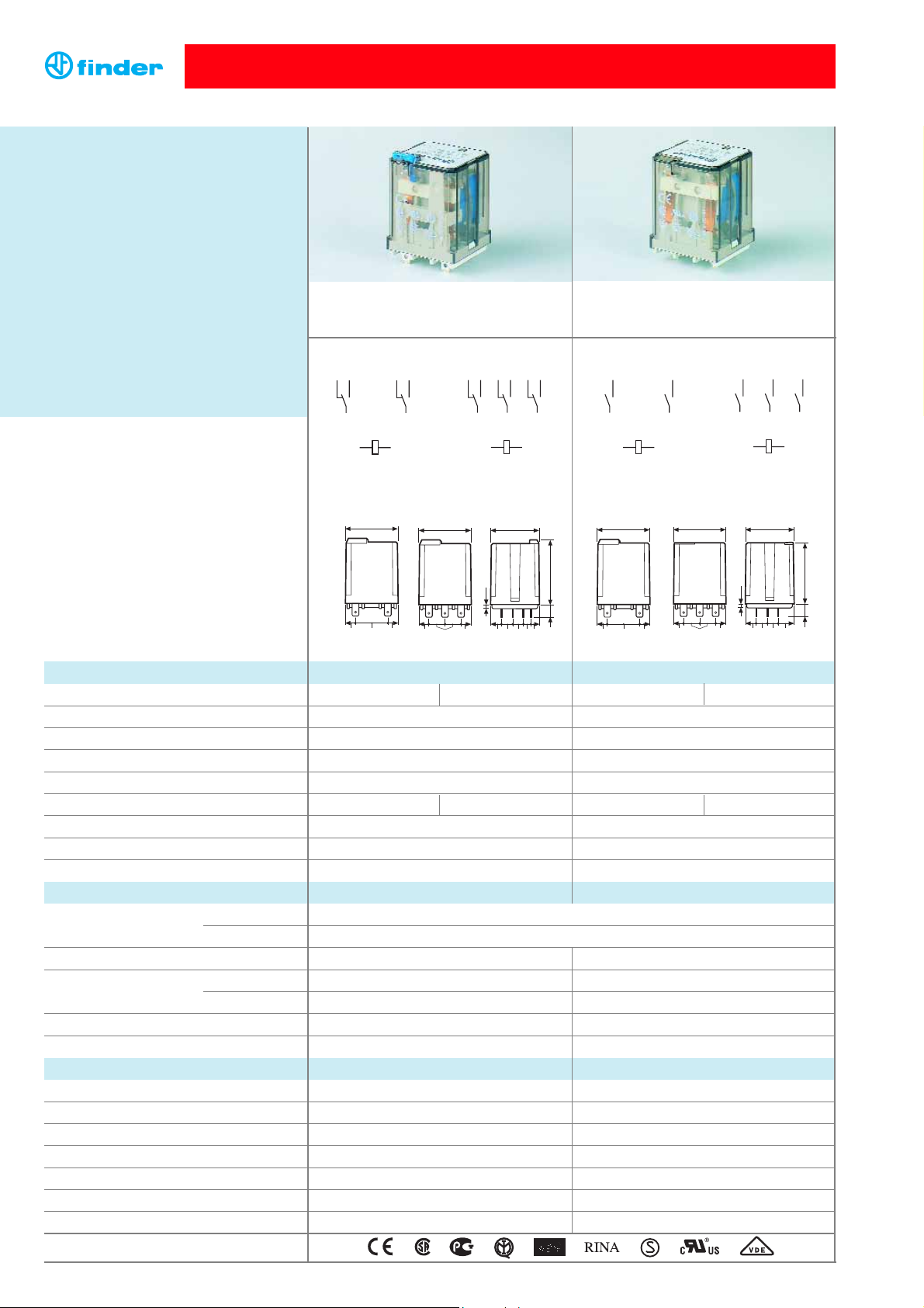
• 2 & 3 pole changeover contact
• Plug-in / Faston 187
• 2 & 3 pole normally open contact
(≥ 3 mm contact gap)
• Plug-in / Faston 187
Contact specification
Contact configuration
Rated current/Maximum peak current A
Rated voltage/Maximum switching voltage V AC
Rated load AC1 VA
Rated load AC15 (230 V AC) VA
Motor rating (230/400 V AC) kW
Breaking capacity DC1: 30/110/220 V A
Minimum switching load mW (V/mA)
Standard contact material
Coil specification
Nominal voltage (U
N
) V AC (50/60 Hz)
V DC
Rated power AC/DC VA (50 Hz)/W
Operating range AC
DC
Holding voltage AC/DC
Must drop-out voltage AC/DC
Technical data
Mechanical life AC/DC cycles
Electrical life at rated load AC1 cycles
Operate/release time ms
Insulation between coil and contacts (1.2/50 µs)
kV
Dielectric strength between open contacts V AC
Ambient temperature range °C
Environmental protection
Approvals (according to type)
* Distance between contacts ≥ 3 mm
(EN 60730-1).
** With the AgSnO
2
material the
maximum
peak
current is 120 A - 5 ms (NO contact).
FORUL H
ORSEPOWER ANDPILOTDUTY RATINGS
SEE“General technical information” page
V
62.32 / 62.33 62.32-0300 / 62.33-0300
Features
Plug-in mount/Faston 187
16 A Power relay
• Plug-in (92 series sockets) or Faston 187
(4.8x0.5 mm) with optional mounting adaptors
• 2 & 3 Pole changeover contacts or NO
(≥ 3 mm contact gap)
• AC coils & DC coils
• UL Listing (certain relay/socket combinations)
• LED, mechanical indicator & test button options
• Reinforced insulation between coil and
contacts according to EN 60335-1, with
6 mm clearance & 8 mm creepage distance
• SELV coil-contact separator option
• Cadmium Free contact material options
• Sockets and accessories
62 Series - Power relays 16 A
88
38.2
22.2
1
7
AB
4
A1 A2
36
9
12 14 32 34
11 31
62.32 62.33
62.32 62.33
62.32-0300 62.33-0300
62.320-00 62.33-0300
2
12 14 22 24 32 34
1
4
25836
11 21 31
7
AB
A1 A2
9
14 34
4
11 31
7
AB
A1 A2
9
6
38.2
8
11.1
35.8
47.6
3.5
8
8.65
7.6 8.35.5 5.75
9.7
38.2
22.2
8
88
14 24 34
4
586
11 21 31
7
AB
A1 A2
38.2
11.1
35.8
3.5
8
8.65
7.6 8.3
11.25
9
45.6
9.7
Page 3
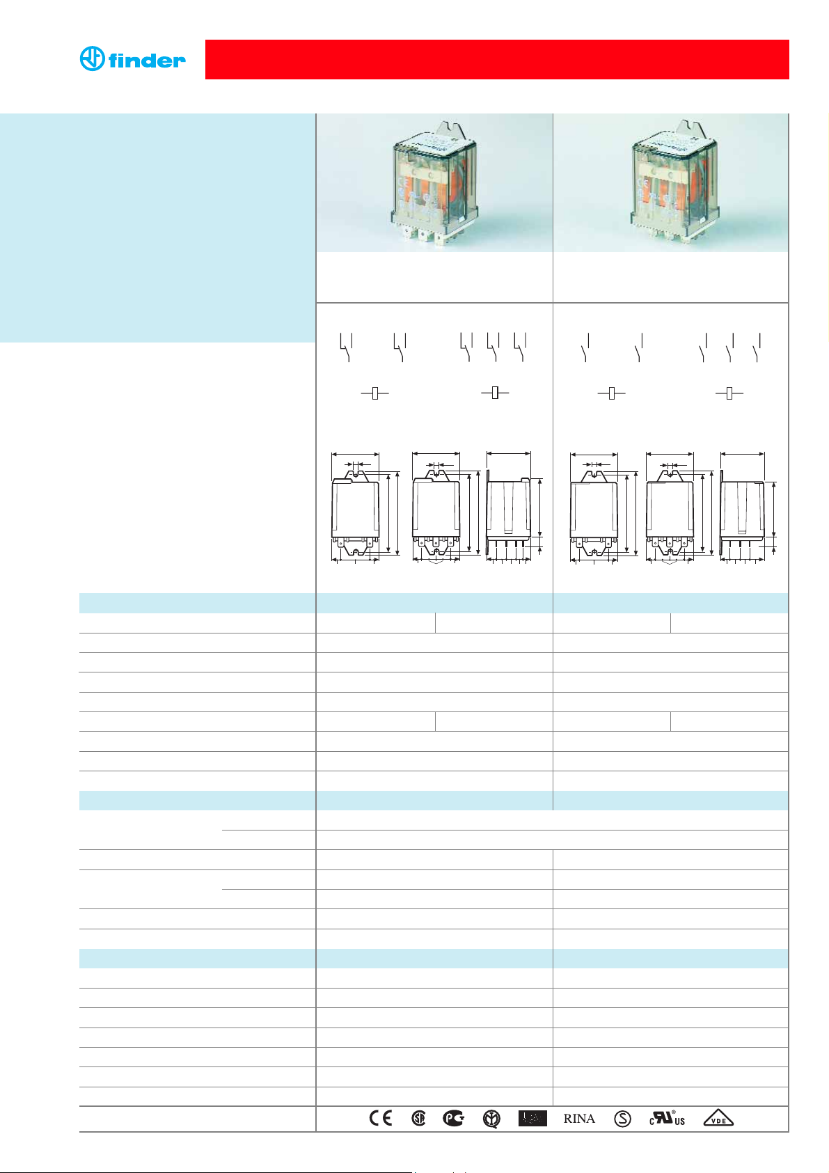
62.82 62.83
2 CO (DPDT) 3 CO (3PDT)
2 NO (DPST-NO), ≥3 mm* 3 NO (3PST-NO), ≥3 mm*
16/30** 16/30**
250/400 250/400
4,000 4,000
750 750
0.8/— 0.8/1.5 0.8/— 0.8/1.5
16/0.6/0.4 16/1.1/0.7
1,000 (10/10) 1,000 (10/10)
AgCdO AgCdO
6 - 12 - 24 - 48 - 60 - 110 - 120 - 230 - 240 - 400
6 - 12 - 24 - 48 - 60 - 110 - 125 - 220
2.2/1.3 3/3
(0.8…1.1)U
N
(0.85…1.1)U
N
(0.8…1.1)U
N
(0.85…1.1)U
N
0.8 UN/0.6 U
N
0.8 UN/0.6 U
N
0.2 UN/0.1 U
N
0.2 UN/0.1 U
N
10 · 106/30 · 10
6
10 · 106/30 · 10
6
100 · 10
3
100 · 10
3
10/10 20/4
66
1,500 2,500
–40…+70 –40…+50
RT I RT I
• 2 & 3 pole changeover contact
• Flange mount / Faston 250
• 2 & 3 pole normally open contact
(≥ 3 mm contact gap)
• Flange mount / Faston 250
Contact specification
Contact configuration
Rated current/Maximum peak current A
Rated voltage/Maximum switching voltage V AC
Rated load AC1 VA
Rated load AC15 (230 V AC) VA
Motor rating (230/400 V AC) kW
Breaking capacity DC1: 30/110/220 V A
Minimum switching load mW (V/mA)
Standard contact material
Coil specification
Nominal voltage (U
N
) V AC (50/60 Hz)
V DC
Rated power AC/DC VA (50 Hz)/W
Operating range AC
DC
Holding voltage AC/DC
Must drop-out voltage AC/DC
Technical data
Mechanical life AC/DC cycles
Electrical life at rated load AC1 cycles
Operate/release time ms
Insulation between coil and contacts (1.2/50 µs)
kV
Dielectric strength between open contacts V AC
Ambient temperature range °C
Environmental protection
Approvals (according to type)
* Distance between contacts ≥ 3 mm
(EN 60730-1).
** With the AgSnO
2
material the
maximum
peak
current is 120 A - 5 ms (NO contact).
FORUL H
ORSEPOWER ANDPILOTDUTY RATINGS
SEE“General technical information” page
V
62.82 / 62.83 62.82-0300 / 62.83-0300
Features
Flange mount/Faston 250
16 A Power relay
• Faston 250 (6.3x0.8 mm) termination Flange
or optional mounting adaptors
• 2 & 3 Pole changeover contacts or NO
(≥ 3 mm contact gap)
• AC coils & DC coils
• LED, mechanical indicator & test button options
• Reinforced insulation between coil and
contacts according to EN 60335-1, with
6 mm clearance & 8 mm creepage distance
• SELV coil-contact separator option
• Cadmium Free contact material options
62 Series - Power relays 16 A
62.82
62.83
62.82-0300
62.82-0300
7
AB
4
A1 A2
6
9
14 34
11 31
88 22.2
63
68
38.2
3.6
62.83-0300
62.83-0300
3
12 14 32 34
1
4
36
11 31
7
AB
A1 A2
38.2
3.6
63
68
88
22.2
12 14 22 24 32 34
1
4
25836
11 21 31
9
7
AB
A1 A2
9
38.2
11.1
3.6
8
35.8
7.688
5.8 5.6
47.6
9.7
63
68
8.8
14 24 34
4
11 21 31
7
A1 A2
38.2
3.6
63
88
11.1
586
9
AB
35.8
68
8.8 7.6811.4
45.6
9.7
Page 4

Example: 62 series power relay + Faston 250 (6.3x0.8 mm), rear flange mount, 2 NO (DPST-NO), 12 V DC coil.
Type Coil version A B C D
62.22/23 AC-DC 0 - 4 0 - 3 - 5 - 6 00
62.32/33 AC-DC 0 - 4 0 - 3 - 5 - 6 0 0 - 5 - 6 - 7 - 8
AC-DC 0 - 4 0 - 5 2 - 40- 6 - 8
AC 0 - 4 0 2 - 3 - 4 - 5 0 - 6 - 8
AC 0 - 4 0 - 3 3 0 - 6 - 8
AC 0 - 4 0 54 /
DC 0 - 4 04- 6 - 7 0 - 6 - 8
DC 0 - 4 0 - 3 6 0 - 6 - 8
DC 0 - 4 0 74 /
62.82/83 AC-DC 0 - 4 0 - 3 - 5 - 6 00- 5 - 7 - 8 - 9
AC-DC 0 - 4 0 - 5 2 - 4 0 - 8
AC 0 - 4 0 2 - 3 - 4 - 5 0 - 8
AC 0 - 4 0 - 3 3 0 - 8
DC 0 - 4 0 4 - 6 - 7 0 - 8
DC 0 - 4 0 - 3 6 0 - 8
4
62 Series - Power relays 16 A
A: Contact material
0 = Standard AgCdO
4 = AgSnO
2
B: Contact circuit
0 = CO (nPDT)
3 = NO (nPST),
≥ 3 mm contact gap
5 = CO (nPDT) + additional
physical separator between
coil and contacts (for SELV
applications)
6 = NO (nPST), ≥ 3 mm contact
gap + additional physical
separator between coil and
contacts (for SELV
applications)
Series
Type
2 = PCB
3 = Plug-in
8 = Faston 250 (6.3x0.8 mm)
with rear flange mount
No. of poles
2 = 2 pole
3 = 3 pole
Coil version
8 = AC (50/60 Hz)
9 = DC
Coil voltage
See coil specifications
8 2 0 39
D: Special versions
0 = Standard
5 = Top flange mount
6 = Rear flange mount
7 = Top 35 mm rail (EN 50022) mount
8 = Rear 35 mm rail (EN 50022) mount
9 = Type 62.82/83 without rear flange
mount
C: Options
0 = None
2 = Mechanical indicator
3 = LED (AC)
4 = Lockable test button +
mechanical indicator
5* = Lockable test button + LED (AC)
54* = Lockable test button + LED (AC) +
mechanical indicator
6* = LED + diode
(DC, polarity positive to pin A/A1)
7* = Lockable test button + LED + diode
(DC, polarity positive to pin A/A1)
74* = Lockable test button + LED + diode
(DC, polarity positive to pin A/A1) +
mechanical indicator
* Options not available for 220 V DC and
400 V AC versions.
0 0
Ordering information
ABCD
... .
01262
Selecting features and options: only combinations in the same row are possible.
Preferred selections for best avaliability are shown in bold.
Lockable test button and mechanical flag indicator
(0040, 0050, 0054, 0070, 0074)
The dual-purpose Finder test button can be used in two ways:
Case 1
) The plastic pip (located directly above the test button) remains intact. In this case, when the
test button is pushed, the contacts operate. When the test button is released the contacts return to their
former state.
Case 2)
The plastic pip is broken-off (using an appropriate cutting tool). In this case, (in addition to
the above function), when the test button is pushed and rotated, the contacts are latched in the
operating state, and remain so until the test button is rotated back to its former position.
In both cases ensure that the test button actuation is swift and decisive.
B: Contact circuit 5, 6
Additional physical separator
between coil and contacts (for
SELV applications)
C: Option 3, 5, 54
LED (AC)
C: Option 6, 7, 74
LED + diode (DC, polarity
positive to pin A/A1)
D: Special versions 5
Top flange mount
D: Special versions 7
Top 35 mm rail
(EN 50022) mount
52.3
A B
B
A
Descriptions: Options and Special versions
Page 5

5
62 Series - Power relays 16 A
Technical data
Insulation according to EN 61810-1:2004
2 CO - 3 CO 2 NO - 3 NO
Nominal voltage of supply system V AC 230/400 230/400
Rated insulation voltage V AC 400 400
Pollution degree 3 3
Insulation between coil and contact set
Type of insulation Reinforced Reinforced
Overvoltage category III III
Rated impulse voltage kV (1.2/50 µs) 6 6
Dielectric strength V AC 4,000 4,000
Insulation between adjacent contacts
Type of insulation Basic Basic
Overvoltage category III III
Rated impulse voltage kV (1.2/50 µs) 4 4
Dielectric strength V AC 2,500 2,500
Insulation between open contacts
Type of disconnection Micro-disconnection Full-disconnection
Overvoltage category — III
Rated impulse voltage kV (1.2/50 µs) — 4
Dielectric strength V AC/kV (1.2/50 µs) 1,500/2 2,500/4
Conducted disturbance immunity
Burst (5...50)ns, 5 kHz, on A1 - A2 EN 61000-4-4 level 4 (4 kV)
Surge (1.2/50 µs) on A1 - A2 (differential mode) EN 61000-4-5 level 4 (4 kV)
Other data
Bounce time: NO/NC ms 3/6 (changeover) 3/— (normally open)
Vibration resistance (10…150)Hz: NO/NC g 20/8
Shock resistance g 15
Power lost to the environment 2 pole (CO) 3 pole (CO) 2 pole (NO) 3 pole (NO)
without contact current W 1.3 1.3 3 3
with rated current W 3.3 4.3 5 6
Recommended distance between relays mounted on PCB mm ≥ 5
Page 6

6
20 60
100 140 180 220
20
10
6
4
2
1
0.2
0.1
1 2 3
20 60
100 140 180 220
20
10
6
4
2
1
0.2
0.1
2 31
(A)
1240
16
8
10
6
10
5
10
7
Contact specification
Voltage DC (V)
DC breeaking current (A)
F 62 - Electrical life (AC) v contact current
H 62 - Maximum DC1 breaking capacity
Normally open contacts
Voltage DC (V)
DC breaking current (A)
H 62 - Maximum DC1 breaking capacity
Changeover contacts
Cycles
• When switching a resistive load (DC1) having voltage and current values under the curve, an electrical life of ≥ 100·103can be expected.
• In the case of DC13 loads, the connection of a diode in parallel with the load will permit a similar electrical life as for a DC1 load.
Note: the release time of the load will be increased.
contacts in series
contacts in series
Resistive load - cosϕ = 1
Inductive load - cosϕ = 0.4
62 Series - Power relays 16 A
Page 7

30
2.0
10-20
1.0
0.5
1.5
0405020-10
U
U
N
60
(°C)
2
1
(°C)
30
2.0
10-20
1.0
0.5
1.5
0405020-10
U
U
N
60
1
2
(°C)
6030 50
2.0
10-20
1.0
0.5
1.5
0407020-10
U
U
N
80
2
1
(°C)
6030 50
2.0
10-20
1.0
0.5
1.5
0407020-10
U
U
N
2
1
7
62 Series - Power relays 16 A
Nominal Coil Operating range Resistance Rated coil
voltage code
consumption
U
N
U
min
U
max
R
I at UN (50Hz)
VVVΩ mA
6 8.006 5.1 6.6 4 540
12 8.012 10.2 13.2 14 275
24 8.024 20.4 26.4 62 130
48 8.048 40.8 52.8 220 70
60 8.060 51 66 348 55
110 8.110 93.5 121 1,200 30
120 8.120 106 137 1,350 24
230 8.230 196 253 5,000 14
240 8.240 204 264 6,300 12.5
400 8.400 340 440 14,700 7.8
Nominal Coil Operating range Resistance Rated coil
voltage code
consumption
U
N
U
min
U
max
R I at U
N
VVVΩ mA
6 9.006 5.1 6.6 12 500
12 9.012 10.2 13.2 48 250
24 9.024 20.4 26.4 192 125
48 9.048 40.8 52.8 770 63
60 9.060 51 66 1,200 50
110 9.110 93.5 121 4,200 26
125 9.125 106.2 137.5 5,200 24
220 9.220 187 242 17,600 12.5
Nominal Coil Operating range Resistance Rated coil
voltage code
consumption
U
N
U
min
U
max
R I at U
N
VVVΩ mA
6 9.006 4.8 6.6 28 214
12 9.012 9.6 13.2 110 109
24 9.024 19.2 26.4 445 54
48 9.048 38.4 52.8 1,770 27
60 9.060 48 66 2,760 21.7
110 9.110 88 121 9,420 11.7
125 9.125 100 137.5 12,000 10.4
220 9.220 176 242 37,300 5.8
Nominal Coil Operating range Resistance Rated coil
voltage code
consumption
U
N
U
min
U
max
R
I at UN(50Hz)
VVVΩ mA
6 8.006 4.8 6.6 4.6 367
12 8.012 9.6 13.2 19 183
24 8.024 19.2 26.4 74 90
48 8.048 38.4 52.8 290 47
60 8.060 48 66 450 37
110 8.110 88 121 1,600 20
120 8.120 96 132 1,940 18.6
230 8.230 184 253 7,250 10.5
240 8.240 192 264 8,500 9.2
400 8.400 320 440 19,800 6
AC version dataDC version data
Coil specifications
DC (NO/nPST-NO) version data - ≥ 3 mm
AC (NO/nPST-NO) version data - ≥ 3 mm
1 - Max. permitted coil voltage.
2 - Min. pick-up voltage with coil at ambient temperature.
1 - Max. permitted coil voltage.
2 - Min. pick-up voltage with coil at ambient temperature.
R 62 - DC coil operating range v ambient temperature
Changeover contacts
R 62 - AC coil operating range v ambient temperature
Changeover contacts
R 62 - DC coil operating range v ambient temperature
Normally open contacts
R 62 - AC coil operating range v ambient temperature
Normally open contacts
Page 8

8
62 Series - Power relays 16 A
062.10
062.10 with relay
062.60
060.72
Accessories
Mounting adaptor for types 62.3x and 62.8x.xxxx.xxx9 (M4) 062.10
Flange mounting adaptor for types 62.3x and 62.8x.xxxx.xxx9 062.60
Sheet of marker tags for 62 series relays, plastic, 72 tags, 6x12 mm 060.72
062.60 with relay
47.2
4.8
7.6
41
47.2
M4
41
37.2
1.4
52.3
36
13
17.3
062.10 with relay
062.60
062.10
062.60 with relay
654
123
789
AB
12
22
3234
24
14
31
21
11
A2
A1
45.6
10
3.6
61
52.3
38.6
1.4
41
654
12 3
78 9
AB
12
22
3234
24
14
31
21
11
A2
A1
41
30.5
M4
38.6 4
9.7 45.6 2
4.8
22.2
Page 9

9
92 Series - Sockets and accessories for 62 series relays
92.03
Approvals
(according to type):
9318217
11
4145246
34
BA2A
A1
COM
NC
NO
1122223
32
COIL
Screw terminal (Box clamp) socket 92.03 92.03.0
panel or 35 mm rail (EN 50022) mount Blue Black
For relay type 62.32, 62.33
Accessories
Metal retaining clip (supplied with socket - packaging code SMA)
092.71
Identification tag 092.00.2
Modules (see table below) 99.02
Timer modules (see table below) 86.00, 86.30
Technical data
Rated values 16 A - 250 V
Insulation 6 kV (1.2/50 µs) between coil and contacts
Protection category IP 20
Ambient temperature °C –40…+70
Screw torque Nm 0.8
Wire strip length mm 10
Max. wire size for 92.03 socket solid wire stranded wire
mm21x10 / 2x4 1x6 / 2x4
AWG 1x8 / 2x12 1x10 / 2x12
DC Modules with
non-standard polarity
(+A2) on request.
99.02
99.02 coil indication and EMC suppression modules for 92.03 socket
Diode (+A1, standard polarity) (6...220)V DC 99.02.3.000.00
LED (6...24)V DC/AC 99.02.0.024.59
LED (28...60)V DC/AC 99.02.0.060.59
LED (110...240)V DC/AC 99.02.0.230.59
LED + Diode (+A1, standard polarity) (6...24)V DC 99.02.9.024.99
LED + Diode (+A1, standard polarity) (28...60)V DC 99.02.9.060.99
LED + Diode (+A1, standard polarity) (110...220)V DC 99.02.9.220.99
LED + Varistor (6...24)V DC/AC 99.02.0.024.98
LED + Varistor (28...60)V DC/AC 99.02.0.060.98
LED + Varistor (110...240)V DC/AC 99.02.0.230.98
RC circuit (6...24)V DC/AC 99.02.0.024.09
RC circuit (28...60)V DC/AC 99.02.0.060.09
RC circuit (110...240)V DC/AC 99.02.0.230.09
Residual current by-pass (110...240)V AC 99.02.8.230.07
86.00
86 series timer modules
Multi-voltage: (12…240)V AC/DC;
Multi-functions: AI, DI, SW, BE, CE, DE, EE, FE; (0.05s…100h) 86.00.0.240.0000
(12…24)V AC/DC; Bi-function: AI, DI; (0.05s…100h) 86.30.0.024.0000
(230...240)V AC; Bi-function: AI, DI; (0.05s…100h) 86.30.8.240.0000
Approvals
(according to type):
86.30
Approvals
(according to type):
40
35.5
60.9
30.25
27
3.2
91.3
35.4 34.321.6
46.3
32
Page 10

92 Series - Sockets and accessories for 62 series relays
92.13
92.33
Approvals
(according to type):
Approvals
(according to type):
40
1.6
5.5
8.3
7.6
11.13611.1==
7.4
7.1
PCB socket 92.13 (blue) 92.13.0 (black)
For relay type 62.32, 62.33
Accessories
Metal retaining clip (supplied with socket - packaging code SMA)
092.54
Technical data
Rated values 16 A - 250 V (10 A max for each contact circuit)
Dielectric strength 2.5 kV AC
Ambient temperature °C –40…+70
Panel mount solder socket mounted with M3 screw 92.33 (blue)
For relay type 62.32, 62.33
Accessories
Metal retaining clip (supplied with socket - packaging code SMA)
092.54
Technical data
Rated values 16 A - 250 V (10 A max for each contact circuit)
Dielectric strength 2.5 kV AC
Ambient temperature °C –40…+70
62.3x plug on 92.13 is 63.3 mm high
A1A A2B
117
144
121
319
346
323
218
245
222
A1A A2B
117
144
121
319
346
323
218
245
222
How to code and identify retaining clip and packaging options for sockets.
Example:
0 3
.
92
Packaging code
A Standard packaging
Without retaining clip
SM Metal retaining clip
SM A
0 3
.
92
10
138
1
36
3.4
19.3
8.3
6.5
11.1
4.5
==
31
11.1
35.5
42.5
138
3.8
8
4.5
1
50
21.3
8.3
6.5
3.4
 Loading...