

Page 1
56
2 CO (DPDT) 2 NO (DPST-NO) - 1.5 mm 4 CO (4PDT)
12/20 12/20 12/20
250/400 250/400 250/400
3,000 3,000 3,000
500 500 500
0.55 0.55 0.55
12/0.25/0.12 12/0.6/0.3 12/0.25/0.12
500 (10/5) 500 (10/5) 500 (10/5)
AgNi AgNi AgNi
6 - 12 - 24 - 48 - 60 - 110 - 120 - 230 - 240 - 400*
6-12-24-48-60-110-125-220 — 6-12-24-48-60-110-125-220
1.5/1 1.5/— 2/1.3
(0.8…1.1)U
N
(0.85…1.1)U
N
(0.8…1.1)U
N
(0.8…1.1)U
N
— (0.85…1.1)U
N
0.8 UN/0.6 U
N
0.85 UN/— 0.8 UN/0.6 U
N
0.2 UN/0.1 U
N
0.2 UN/— 0.2 UN/0.1 U
N
20 · 106/50 · 10
6
20 · 106/— 20 · 106/50 · 10
6
200 · 10
3
200 · 10
3
150 · 10
3
8/8 8/4 8/8
445
1,000 2,000 1,000
–40…+70 –40…+70 –40…+70
RT I RT I RT I
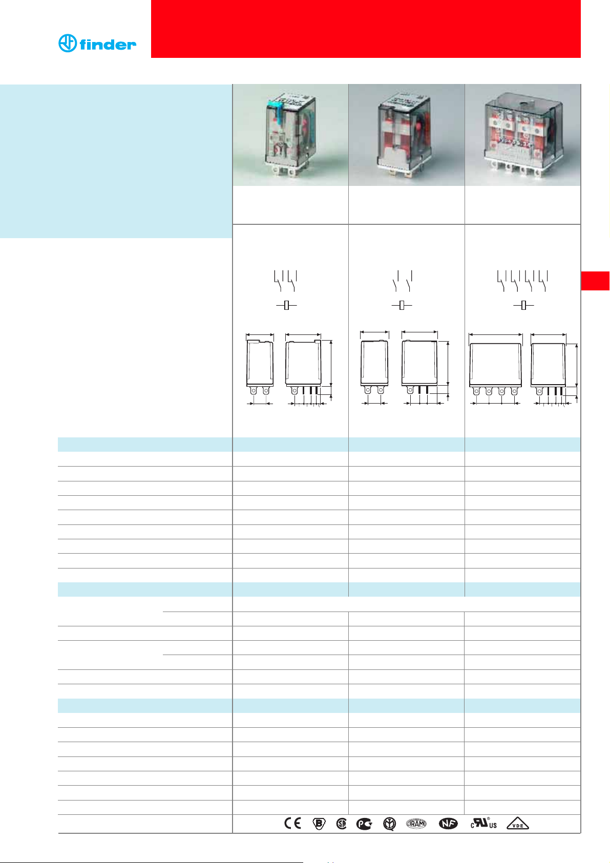
56.32 56.32-0300 56.34
• 2 pole changeover contact
• Plug-in/Faston 187
• 2 pole normally open
contact (1.5 mm gap)
• Plug-in/Faston 187
• 4 pole changeover contact
• Plug-in/Faston 187
41
10
7.25
27.8
35.2
6.5
5.9 4.75 3.85
10 10
1
9
13 14
5
A1 A2
2610371148
12
20.7
10
7.25
27.7
36.3
6.5
5.9 8.6
5
78
3
A1 A2
4
6
20.7
10
7.25
27.7
37.7
6.5
5.9 4.75 3.85
1
5
78
3
A1 A2
24
6
Contact specification
Contact configuration
Rated current/Maximum peak current A
Rated voltage/Maximum switching voltage V AC
Rated load AC1 VA
Rated load AC15 (230 V AC) VA
Single phase motor rating (230 V AC) kW
Breaking capacity DC1: 30/110/220 V A
Minimum switching load mW (V/mA)
Standard contact material
Coil specification
Nominal voltage (U
N
) V AC (50/60 Hz)
V DC
Rated power AC/DC VA (50 Hz)/W
Operating range AC
DC
Holding voltage AC/DC
Must drop-out voltage AC/DC
Technical data
Mechanical life AC/DC cycles
Electrical life at rated load AC1 cycles
Operate/release time ms
Insulation between coil and contacts (1.2/50 µs)
kV
Dielectric strength between open contacts V AC
Ambient temperature range °C
Environmental protection
Approvals (according to type)
Features
* For 4 CO (4PDT) only.
75
Plug-in
12 A Power relay, 2 & 4 pole
• Flange mount option -
(Faston 187, 4.8x0.5 mm termination)
• AC coils & DC coils
• Lockable test button and mechanical flag
indicator - standard on 2 pole types
• Cadmium Free contacts
(preferred version)
• Contact material options
• 96 series sockets, coil EMC suppression,
accessories
56 Series - Miniature power relays 12 A
Page 2
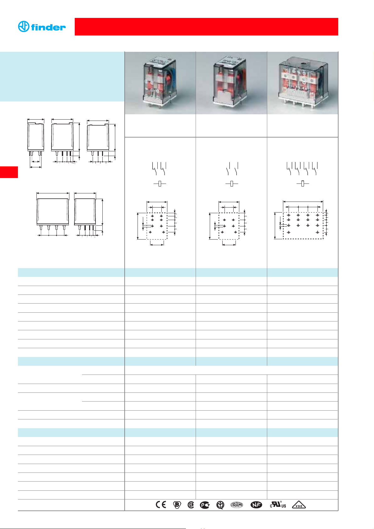
2 CO (DPDT) 2 NO (DPST-NO) 1.5 mm 4 CO (4PDT)
12/20 12/20 12/20
250/400 250/400 250/400
3,000 3,000 3,000
500 500 500
0.55 0.55 0.55
12/0.25/0.12 12/0.6/0.3 12/0.25/0.12
500 (10/5) 500 (10/5) 500 (10/5)
AgNi AgNi AgNi
6 - 12 - 24 - 48 - 60 - 110 - 120 - 230 - 240 - 400*
6-12-24-48-60-110-125-220 — 6-12-24-48-60-110-125-220
1.5/1 1.5/— 2/1.3
(0.8…1.1)U
N
(0.85…1.1)U
N
(0.8…1.1)U
N
(0.8…1.1)U
N
— (0.85…1.1)U
N
0.8 UN/0.6 U
N
0.85 UN/— 0.8 UN/0.6 U
N
0.2 UN/0.1 U
N
0.2 UN/— 0.2 UN/0.1 U
N
20 · 106/50 · 10
6
20 · 106/— 20 · 106/50 · 10
6
200 · 10
3
200 · 10
3
150 · 10
3
8/8 8/4 8/8
445
1,000 2,000 1,000
–40…+70 –40…+70 –40…+70
RT I RT I RT I
76
• 2 pole changeover contact
• PCB mount
•
2 pole normally open contact
(1.5 mm gap)
• PCB mount
• 4 pole changeover contact
• PCB mount
1
9
13 14
5
A1 A2
2610371148
12
1 2 3 4
5 6 7 8
9 10 11 12
13 14
41
10 10 10
3.85
4.75
5.9
7.25
2.5
27.6
5
78
3
A1 A2
4
6
20.7
43
65
87
10
27.7
2.5
8.6
5.9
7.25
14.2
1
5
78
3
A1 A2
24
6
20.7
21
43
65
87
10
27.7
2.5
3.85
4.75
5.9
7.25
14.2
Contact specification
Contact configuration
Rated current/Maximum peak current A
Rated voltage/Maximum switching voltage V AC
Rated load AC1 VA
Rated load AC15 (230 V AC) VA
Single phase motor rating (230 V AC) kW
Breaking capacity DC1: 30/110/220 V A
Minimum switching load mW (V/mA)
Standard contact material
Coil specification
Nominal voltage (U
N
) V AC (50/60 Hz)
V DC
Rated power AC/DC VA (50 Hz)/W
Operating range AC
DC
Holding voltage AC/DC
Must drop-out voltage AC/DC
Technical data
Mechanical life AC/DC cycles
Electrical life at rated load AC1 cycles
Operate/release time ms
Insulation between coil and contacts (1.2/50 µs)
kV
Dielectric strength between open contacts V AC
Ambient temperature range °C
Environmental protection
Approvals (according to type)
* For 4 CO (4PDT) only
Copper side view Copper side view Copper side view
56 Series - Miniature power relays 12 A
56.42 56.42-0300 56.44
20.7
10
7.25
27.7
37.7
6.5
5.9 4.75 3.85 7.25
27.7
36.3
6.5
5.9 8.6
14.2
41
10
7.25
27.8
35.2
6.5
5.9 4.75 3.85
10 10
56.44
56.42
56.42-0300
Features
Printed circuit mount
12 A Power relay
• 2 & 4 pole
• AC coils & DC coils
•
Cadmium Free contacts (preferred version)
• Contact material option
56
Page 3

77
7 8
A1 A2
78
A1 A2
78
A1 A2
C: Option 3, 5, 54
LED (AC)
C: Option 6, 7, 74
Double LED
(DC non-polarized)
C: Option 8, 9, 94
LED + diode (DC, polarity
positive to pin 7)
Example: 56 series plug-in relay, 2 CO (DPDT), 12 V DC coil, lockable test button and mechanical indicator.
A: Contact material
0 = Standard AgNi
2 = AgCdO
4 = AgSnO
2
B: Contact circuit
0 = CO (nPDT)
3 = NO (nPST),
1.5 mm contact gap
Series
Type
3 = Plug-in
4 = PCB
No. of poles
2 = 2 pole, 12 A
4 = 4 pole, 12 A
Coil version
8 = AC (50/60 Hz)
9 = DC
Coil voltage
see coil specifications
3 2 0 09
D: Special versions
0 = Standard
5 = Top flange mount (56.34 only)
6 = Rear flange mount
7 = Top 35 mm rail mount (56.34 only)
8 = Rear 35 mm rail mount (56.34 only)
C: Options
0 = None
1 = Test button
2 = Mechanical indicator
3 = LED (AC)
4=
Lockable test button+mechanical indicator
5 = Lockable test button + LED (AC)
54 = Lockable test button + LED (AC) +
mechanical indicator
6 = Double LED (DC non-polarized)
7 = Lockable test button + double LED
(DC non-polarized)
74 = Lockable test button + double LED
(DC non-polarized) +
mechanical indicator
8=
LED + diode (DC, polarity positive to pin 7)
9 = Lockable test button + LED + diode
(DC, polarity positive to pin 7)
94 = Lockable test button + LED + diode
(DC, polarity positive to pin 7) +
mechanical indicator
4 0
Ordering information
ABCD
... .
01256
Lockable test button and mechanical flag indicator
(0040)
The dual-purpose Finder test button can be used in two ways:
Case 1
) The plastic pip (located directly above the test button) remains intact. In this case, when the
test button is pushed, the contacts operate. When the test button is released the contacts return to their
former state.
Case 2)
The plastic pip is broken-off (using an appropriate cutting tool). In this case, (in addition to
the above function), when the test button is pushed and rotated, the contacts are latched in the
operating state, and remain so until the test button is rotated back to its former position.
In both cases ensure that the test button actuation is swift and decisive.
D: Special versions 6
Rear flange mount
(56.34 only)
41.9
3
.6
Type Coil version A B C D
56.32 AC 0 - 2 - 4 0 0 - 2 - 3 - 4 - 5 0 - 6
AC 0 - 2 - 4 0 54 /
AC 0 - 2 - 4 3 0 - 3 - 5 0 - 6
DC 0 - 2 - 4 0 0 - 2 - 4 - 8 - 9 0 - 6
DC 0 - 2 - 4 0 94 /
56.34 AC-DC 0 - 2 - 4 00- 1 0 - 5 - 6 - 7 - 8
56.42 AC 0 - 2 - 4 0 - 3 00
56.44 AC-DC 0 - 2 - 4 00 0
Selecting features and options: only combinations in the same row are possible.
Preferred selections for best avaliability are shown in bold.
56 Series - Miniature power relays 12 A
Descriptions: Options and Special versions
56
D: Special versions 8
Rear 35 mm rail mount
(56.34 only)
Page 4

56
78
Technical data
56 Series - Miniature power relays 12 A
Contact specification
F 56 - Electrical life (AC) v contact current
2 pole relays
Cycles
DC voltage (V)
DC breajking current (A)
• When switching a resistive load (DC1) having voltage and current values under the curve, an electrical life of ≥ 100·103can be expected.
• In the case of DC13 loads, the connection of a diode in parallel with the load will permit a similar electrical life as for a DC1 load.
Note: the release time of the load will increased.
DC voltage (V)
DC breaking current (A)
Resistive load - cosϕ= 1
Inductive load - cosϕ = 0.4
H 56 - Maximum DC1 breaking capacity
Changeover version
H 56 - Maximum DC1 breaking capacity
Normally open version
contacts in series
contacts in series
F 56 - Electrical life (AC) v contact current
4 pole relays
Cycles
Resistive load - cosϕ= 1
Inductive load - cosϕ = 0.4
Insulation
Insulation according to EN 61810-1 ed. 2 insulation rated voltage V 250 400
rated impulse withstand voltage kV 4 4
pollution degree 3 2
overvoltage category III III
Insulation between coil and contacts (1.2/50 µs) kV 4 (2 contacts); 5 (4 contacts)
Dielectric strength between open contacts V AC 1,000 (changeover); 2,000 (normally open)
Dielectric strength between adjacent contacts V AC 2,500
Conducted disturbance immunity
Burst (5...50)ns, 5 kHz, on A1 - A2 EN 61000-4-4 level 4 (4 kV)
Surge (1.2/50 µs) on A1 - A2 (differential mode) EN 61000-4-5 level 4 (4 kV)
Other data
Bounce time: NO/NC ms 1/3 (changeover) 3/— (normally open)
Vibration resistance (5...55)Hz, max. ± 1 mm: NO/NC g/g 15/15
Shock resistance g 16
Power lost in the environment 2 pole 4 pole
without contact current W 1 1.3
with rated current W 3.8 6.9
Recommended distance between relays mounted on PCB mm ≥ 5
7
10
6
10
5
10
20
10
1 2 3 4
6
4
2
1
7
10
6
10
5
10
8
1240
16
(A)
8
1240
16
(A)
20
10
1
6
4
2
1
2
0.2
0.1
20 60
100 140 180 220
0.2
0.1
20 60
100 140 180 220
Page 5

56
56 Series - Miniature power relays 12 A
79
60
2.0
-20
1.0
0.5
1.5
04020
U
U
N
80-10 10 30
50 70
(°C)
2
1
60
2.0
-20
1.0
0.5
1.5
04020
U
U
N
80
-10 10
30 50
70
(°C)
2
1
60
2.0
-20
1.0
0.5
1.5
04020
U
U
N
80
-10 10 30
50 70
(°C)
1
2
2
60
2.0
-20
1.0
0.5
1.5
04020
U
U
N
80
-10 10 30
50 70
(°C)
2
1
Nominal Coil Operating range Resistance Rated coil
voltage code
consumption
U
N
U
min
U
max
R
I at UN(50Hz)
VVVΩ mA
6 8.006 4.8 6.6 5.7 300
12 8.012 9.6 13.2 22 150
24 8.024 19.2 26.4 81 90
48 8.048 38.4 52.8 380 37
60 8.060 48 66 600 30
110 8.110 88 121 1,900 16.5
120 8.120 96 132 2,560 13.4
230 8.230 184 253 7,700 9
240 8.240 192 264 10,000 7.5
400 8.400 320 440 26,000 4.9
Nominal Coil Operating range Resistance Rated coil
voltage code
consumption
U
N
U
min
U
max
R I at U
N
VVVΩ mA
6 9.006 4.8 6.6 40 150
12 9.012 9.6 13.2 140 86
24 9.024 19.2 26.4 600 40
48 9.048 38.4 52.8 2,400 20
60 9.060 48 66 4,000 15
110 9.110 88 121 12,500 8.8
125 9.125 100 137.5 17,300 7.2
220 9.220 176 242 54,000 4
Nominal Coil Operating range Resistance Rated coil
voltage code
consumption
U
N
U
min
*U
max
R
I at UN(50Hz)
VVVΩ mA
6 8.006 4.8 6.6 12 200
12 8.012 9.6 13.2 50 97
24 8.024 19.2 26.4 190 53
48 8.048 38.4 52.8 770 25
60 8.060 48 66 1,200 21
110 8.110 88 121 3,940 12.5
120 8.120 96 132 4,700 12
230 8.230 184 253 17,000 6
240 8.240 192 264 19,100 5.3
AC coil data, 2 pole relayDC coil data, 2 pole relay
Nominal Coil Operating range Resistance Rated coil
voltage code
consumption
U
N
U
min
U
max
R I at U
N
VVVΩ mA
6 9.006 5.1 6.6 32.5 185
12 9.012 10.2 13.2 123 97
24 9.024 20.4 26.4 490 49
48 9.048 40.8 52.8 1,800 27
60 9.060 51 66 3,000 20
110 9.110 93.5 121 10,400 10.5
125 9.125 107 137.5 14,200 8.8
220 9.220 187 242 44,000 5
AC coil data, 4 pole relayDC coil data, 4 pole relay
Coil specifications
1 - Max. permitted coil voltage.
2 - Min. pick-up voltage with coil at ambient temperature.
R 56 - AC coil operating range v ambient temperature
2 pole relay
R 56 - DC coil operating range v ambient temperature
2 pole relay
R 56 - DC coil operating range v ambient temperature
4 pole relay
R 56 - AC coil operating range v ambient temperature
4 pole relay
1 - Max. permitted coil voltage.
2 - Min. pick-up voltage with coil at ambient temperature.
*
U
min
= 0.85 UNfor normally open version.
normally open version
changeover version
Page 6

80
56 Series - Miniature power relays 12 A
056.05
Adaptor with top mount flange for 56.32.x.xxx.xx00 056.05
Accessories
15
37.5
3.6
34.3
1.7
2
44.4
056.05 with relay
56
Page 7

96 Series - Sockets and accessories for 56 series relays
96.72
Approvals
(according to type):
99.01
99.01 coil indication and EMC suppression modules for types 96.72 and 96.74 sockets
See technical data pages 247/248 Blue*
Diode (+A1, standard polarity) (6...220)V DC 99.01.3.000.00
Diode (+A2, non-standard polarity) (6...220)V DC 99.01.2.000.00
LED (6...24)V DC/AC 99.01.0.024.59
LED (28...60)V DC/AC 99.01.0.060.59
LED (110...240)V DC/AC 99.01.0.230.59
LED + Diode (+A1, standard polarity) (6...24)V DC 99.01.9.024.99
LED + Diode (+A1, standard polarity) (28...60)V DC 99.01.9.060.99
LED + Diode (+A1, standard polarity) (110...220)V DC 99.01.9.220.99
LED + Diode (+A2, non-standard polarity) (6...24)V DC 99.01.9.024.79
LED + Diode (+A2, non-standard polarity) (28...60)V DC 99.01.9.060.79
LED + Diode (+A2, non-standard polarity) (110...220)V DC 99.01.9.220.79
LED + Varistor (6...24)V DC/AC 99.01.0.024.98
LED + Varistor (28...60)V DC/AC 99.01.0.060.98
LED + Varistor (110...240)V DC/AC 99.01.0.230.98
RC circuit (6...24)V DC/AC 99.01.0.024.09
RC circuit (28...60)V DC/AC 99.01.0.060.09
RC circuit (110...240)V DC/AC 99.01.0.230.09
Residual current by-pass (62 kΩ/1W) (110...240)V AC 99.01.8.230.07
* Modules in Black
housing are
available on request.
Green LED is standard.
Red LED available on
request.
Approvals
(according to type):
Screw terminal (Plate clamp) socket 96.72 (blue)
96.72.0 (black)
96.74 (blue)96.74.0 (black)
panel or 35 mm rail (EN 50022) mount
For relay type 56.32 56.34
Accessories
Metal retaining clip (supplied with socket - packaging code SMA)
094.71 096.71
Modules (see table below) 99.01
Technical data
Rated values 12 A - 250 V
Dielectric strength ≥ 2 kV AC
Protection category IP 20
Ambient temperature °C –40…+70
Screw torque Nm 0.8
Wire strip length mm 10
Max. wire size for 96.72 and 96.74 sockets solid wire stranded wire
mm21x4 / 2x4 1x4 / 2x2.5
AWG 1x12 / 2x12 1x12 / 2x14
96.74
81
96.72
56
3.5
4
12
22
NC
1
2
24
14
NO
4
3
11
21
COM
5
6
A2
A1
COIL
8
7
5
78
5
3
27
42
32
12
22
2
211011
NC
1
14524634
NO
COM
9
A1
COIL
13
4
3
44
8
7
41
31
12
11
A2
14
3.5
4
5
78
6.5
46
3523.6 19.4
5
33.5
27
30
Page 8

82
96 Series - Sockets and accessories for 56 series relays
Copper side view
119
145
121
A113 A214
3111
347
323
2110
246
222
4112
448
424
115
143
121
A113 A214
216
244
222
Copper side view
96.12
Approvals
(according to type):
PCB socket 96.12 (blue)
96.12.0 (black)
96.14 (blue)96.14.0 (black)
For relay type 56.32 56.34
Accessories
Metal retaining clip (supplied with socket - packaging code SMA)
094.51
Technical data
Rated values 15 A - 250 V
Dielectric strength ≥ 2 kV AC
Protection category IP 20
Ambient temperature °C –40…+70
How to code and identify retaining clip and packaging options for sockets.
Code options according to the last three letters:
7 4
.
96
Packaging code
A Standard packaging
Without retaining clip
SM Metal retaining clip
SM A
7 4
.
96
96.12
14.3
4.5
11.3
25
96.14
56
29.5
21.5
10
4.7
2.5
5.9
6.1
16.6
21.5
29.5
41.5
29.5
10 1010
2.5
4.7
5.9
29.5
6.1
41.5
4.5
14.3
25
32.2
11.3
 Loading...